

Page 1
Cleaning Instructions,
®
Pilot Replacement and
Valve Change
Model No.:
233010
Natural Gas
Page 2
®
Cleaning burner, pilot replacement and valve change. Model No. 233010 Natural Gas 501310 2
®
For assistance call 1.800.762.1142.
Tools required:
• 8mm open-end wrench
• 9mm open-end wrench
• 10mm open-end wrench
• 12mm open-end wrench
• 13mm open-end wrench
• Phillips screw driver
• 5/8” open end wrench
• 3/4” open end wrench
• Needle nose pliers
• Soap and water solution (to check for leaks)
For assistance call 1.800.762.1142.
DANGERS and Cautions
1. Installation and repair should be done by a qualified service person.
2. Use only Blue Rhino Global Sourcing, LLC. factory authorized parts. The use of any
part that is not factory authorized can be dangerous. This will also void your warranty.
Contact 1.800.762.1142.
3. Do not use flammable solutions or material to clean heater or heater parts. Use only
warm soapy water to clean outside of heater.
4. Do not submerge control valve in water.
Cleaning burner, pilot replacement and valve change. Model No. 233010 Natural Gas 501310 1
Page 3

®
For assistance call 1.800.762.1142.
Steps 1-4
1. Turn gas supply off and disconnect from gas supply. Important: make sure your gas supply is off.
2. Remove dome.
3. Remove engine from post.
Cleaning burner, pilot replacement and valve change. Model No. 233010 Natural Gas 501310 2
Page 4
®
Cleaning burner, pilot replacement and valve change. Model No. 233010 Natural Gas 501310 4
®
For assistance call 1.800.762.1142.
For assistance call 1.800.762.1142.
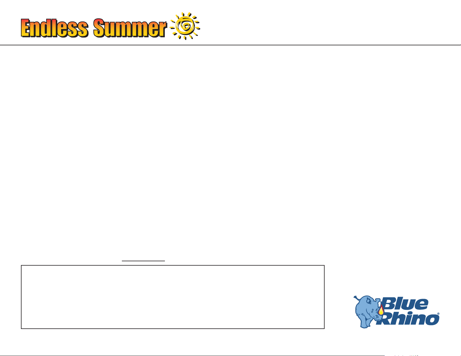
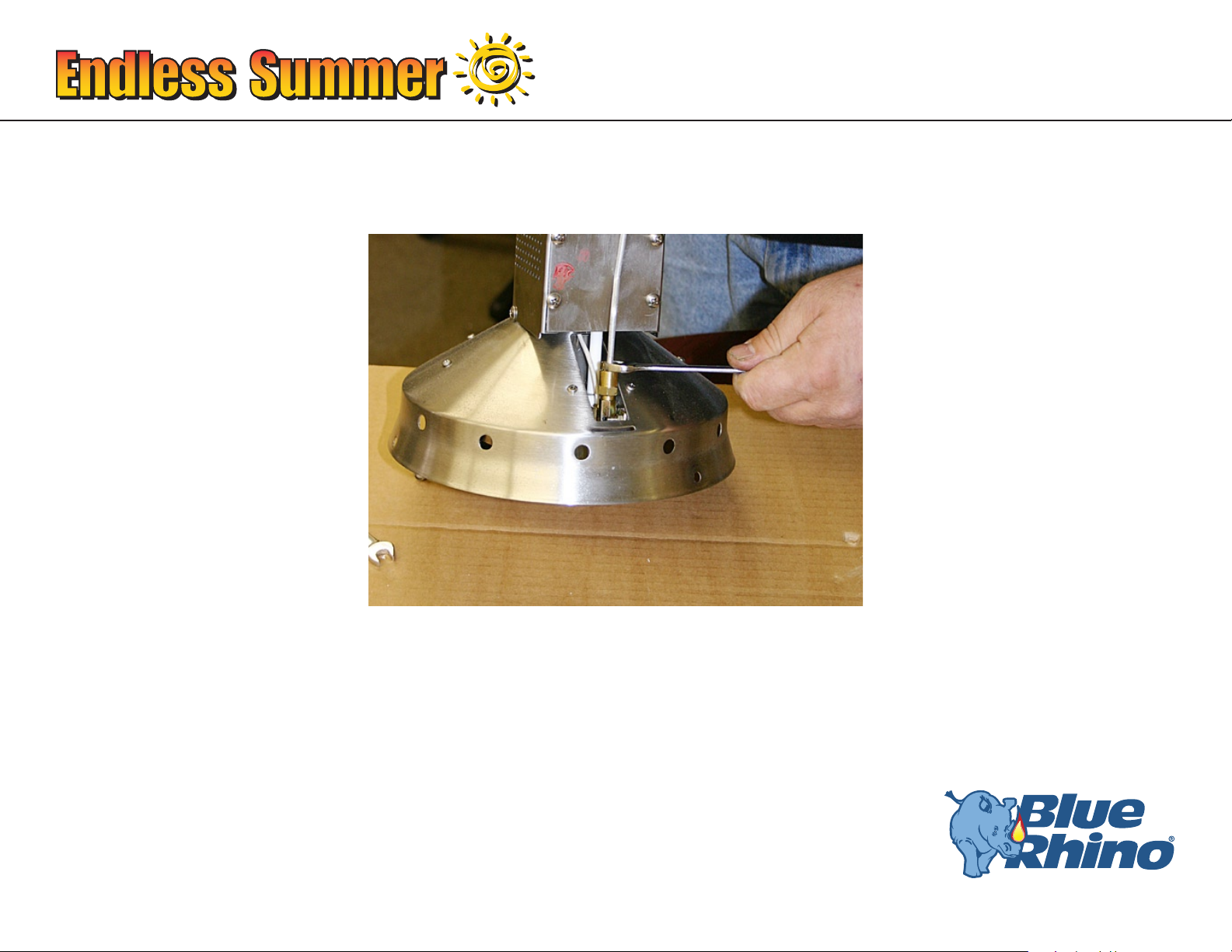
Step 5
Remove the three bolts which secure the emitter to the emitter bottom using a 9mm wrench.
Cleaning burner, pilot replacement and valve change. Model No. 233010 Natural Gas 501310 3
Page 5
®
For assistance call 1.800.762.1142.
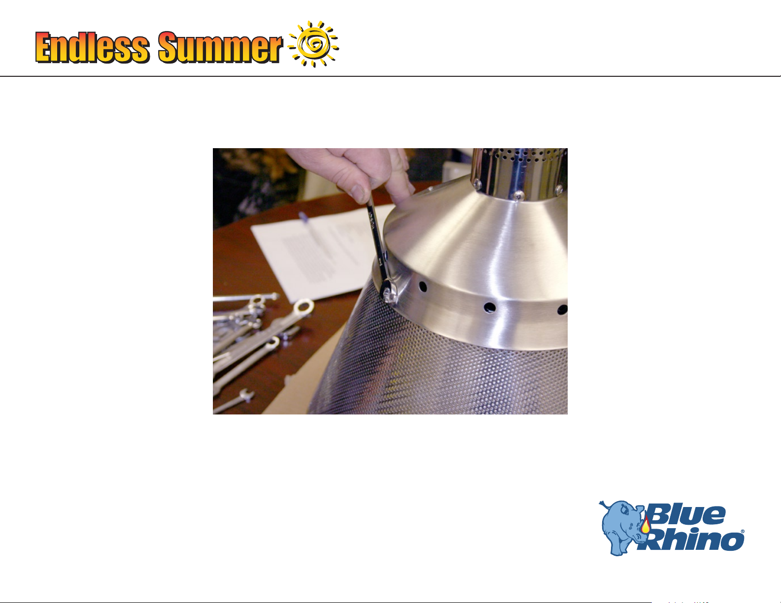
Step 6
1. Clean the carbon build-up off the inside of the emitter bottom with a non-abrasive scouring pad or bottle brush.
Clean the outside of the emitter bottom with the scouring pad.
2. Use the air compressor to blow away any excess soot.
DANGER: Never use any ammable solutions or material to clean heater or heater parts. Use only a mild
soap and water solution.
Do not to soak the valve.
Cleaning burner, pilot replacement and valve change. Model No. 233010 Natural Gas 501310 4
Page 6
®
Cleaning burner, pilot replacement and valve change. Model No. 233010 Natural Gas 501310 6
®
For assistance call 1.800.762.1142.
For assistance call 1.800.762.1142.
Step 7
Disconnect the pilot supply tube using #10 open-ended wrench.
Cleaning burner, pilot replacement and valve change. Model No. 233010 Natural Gas 501310 5
Page 7
®
For assistance call 1.800.762.1142.
Step 8
Disconnect the burner supply tube from the control valve using 5/8” open-ended wrench.
Cleaning burner, pilot replacement and valve change. Model No. 233010 Natural Gas 501310 6
Page 8
®
Cleaning burner, pilot replacement and valve change. Model No. 233010 Natural Gas 501310 8
®
For assistance call 1.800.762.1142.
For assistance call 1.800.762.1142.
Step 9
1. Disconnect the burner from the emitter bottom by removing the 2 phillips screws on the bottom of the emitter
bottom.
2. Carefully remove the burner.
Cleaning burner, pilot replacement and valve change. Model No. 233010 Natural Gas 501310 7
Page 9
®
For assistance call 1.800.762.1142.
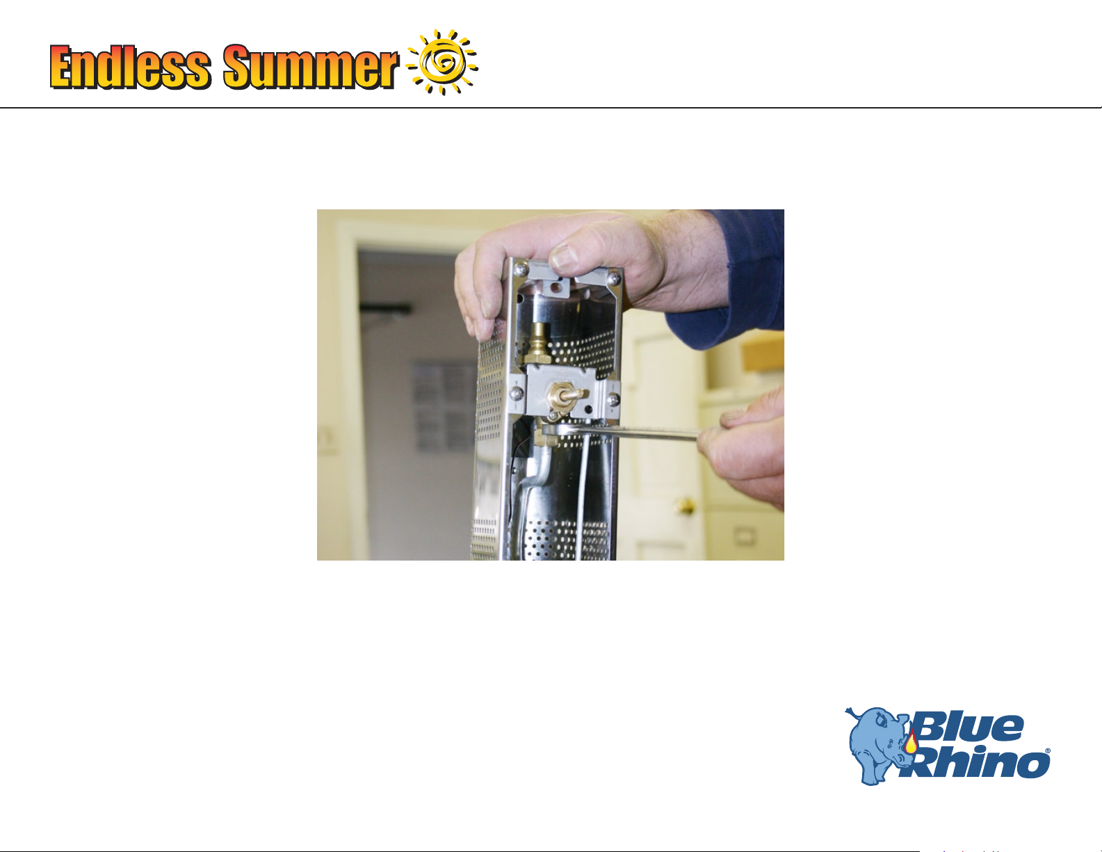
Step 10
Disconnect the thermal couple wire from the control valve:
1. Remove the screw that holds the access panel to the housing.
2. Remove the nut from the back of the control valve using 8 mm open-ended wrench.
Note: Be very careful not to damage any wires.
Cleaning burner, pilot replacement and valve change. Model No. 233010 Natural Gas 501310 8
Page 10

®
Cleaning burner, pilot replacement and valve change. Model No. 233010 Natural Gas 501310 10
®
For assistance call 1.800.762.1142.
For assistance call 1.800.762.1142.
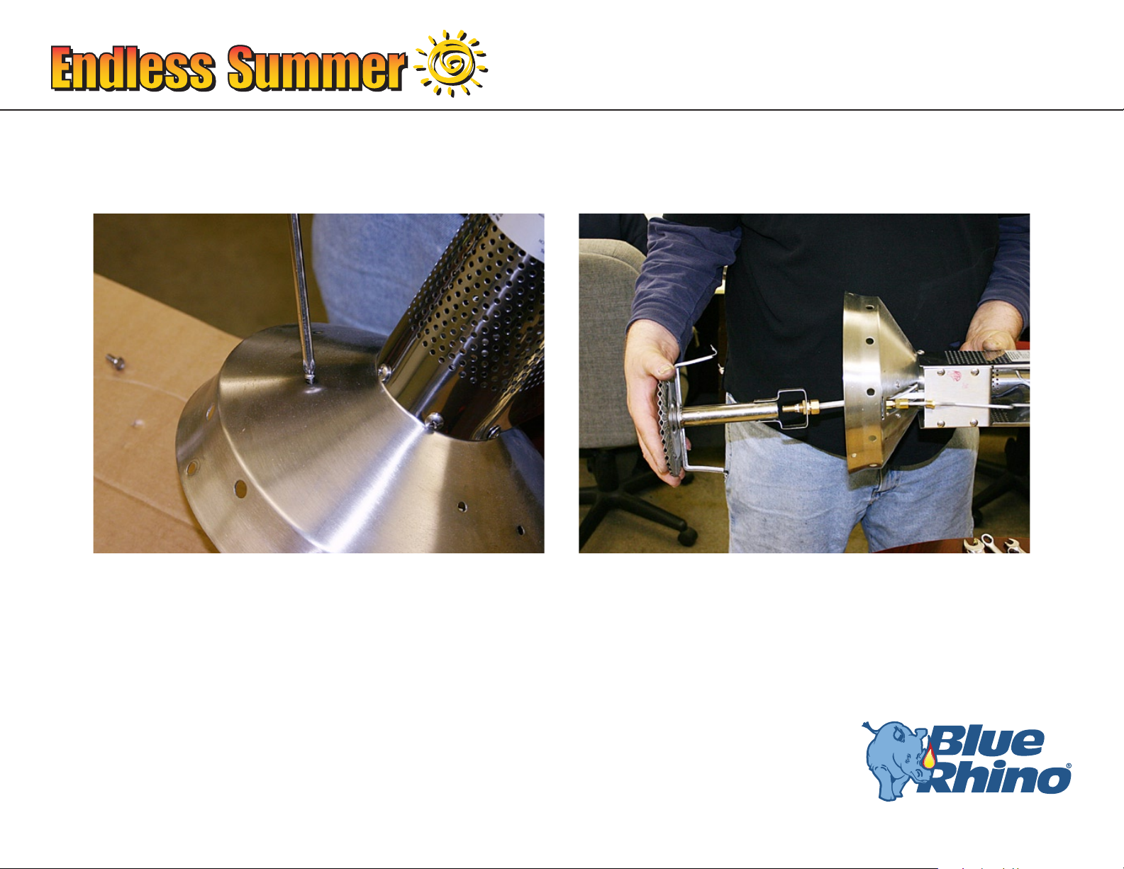
Step 11
Remove the heat and pilot shield from the emitter bottom.
1. Remove the 4 screws in emitter bottom.
Note: 2 screws are near pilot opening, and 2 screws are on the back side of the emitter bottom.
2. Lift the heat shield assembly out.
Note: Be very careful not to damage any wires.
Cleaning burner, pilot replacement and valve change. Model No. 233010 Natural Gas 501310 9
Page 11

®
For assistance call 1.800.762.1142.
Step 12
1. Remove the pilot assembly by removing the 2 screws that hold the pilot assembly in place
Note: you may need to use a pair of needle nose pliers to hold the nuts in place.
2. If replacing the pilot:
A. Remove the ignitor wire, by carefully bending the fork on the retaining bracket up using need nose pliers
B. Pull down on the ceramic tube
C. Disconnect the igniter wire from the pilot.
D. Replace the old pilot with the new pilot, re-attch the ignitor wire, slide the ceramic
tube back up, and bend the fork to the proper place.
3. Reattach the pilot assembly.
Cleaning burner, pilot replacement and valve change. Model No. 233010 Natural Gas 501310 10
Page 12

®
Cleaning burner, pilot replacement and valve change. Model No. 233010 Natural Gas 501310 12
®
For assistance call 1.800.762.1142.
For assistance call 1.800.762.1142.
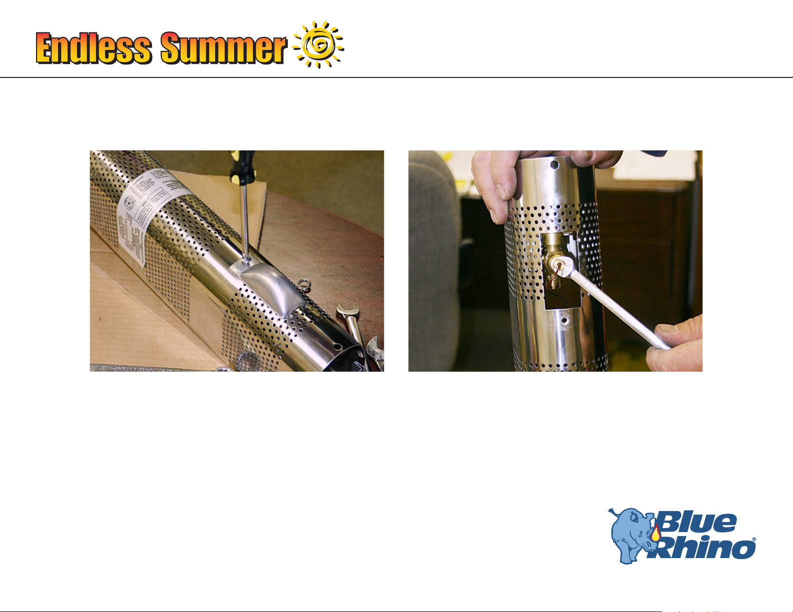
Step 13
1. Remove the orice by placing the 12 mm open-ended on the pilot orice and the 10 mm open-ended on the hex
tube just below the pilot hood.
2. Use a pipe cleaner to clean both the inside and outside of the pilot orice.
3. With a brush, lightly clean the top of the pilot orice. Use care not to enlarge the orice hole.
Cleaning burner, pilot replacement and valve change. Model No. 233010 Natural Gas 501310 11
Page 13

®
For assistance call 1.800.762.1142.
1. Use a heavy-duty pipe cleaner to clean the bottom of the black hex tube on the pilot assembly. Make sure to
extend the pipe cleaner past the silver hood.
2. Clean the port at the side of the pilot hood with a heavy-duty pipe cleaner.
3. Blow out any excess soot or debris with an air hose or a can of compressed air.
Cleaning burner, pilot replacement and valve change. Model No. 233010 Natural Gas 501310 12
Page 14

®
Cleaning burner, pilot replacement and valve change. Model No. 233010 Natural Gas 501310 14
®
For assistance call 1.800.762.1142.
For assistance call 1.800.762.1142.
Step 14
Insert bottle brush into venturi tube and give a couple of twists. This will clear any debris or spider webs from the
venturi tube.
Cleaning burner, pilot replacement and valve change. Model No. 233010 Natural Gas 501310 13
Page 15

®
For assistance call 1.800.762.1142.
Step 15
1. Insert a heavy-duty pipe cleaner into each burner port to clean them. Use a non-abrasive scouring pad to clean
the outside of the burner.
2. Using an air hose or can of compressed air to blow any excess soot from the burner ports and the venturi tube.
3. Use a brush or compressed air to clean the burner orice.
Note: Be careful not to enlarge any holes.
Cleaning burner, pilot replacement and valve change. Model No. 233010 Natural Gas 501310 14
Page 16

®
Cleaning burner, pilot replacement and valve change. Model No. 233010 Natural Gas 501310 16
®
For assistance call 1.800.762.1142.
For assistance call 1.800.762.1142.
Step 16
If this is all you need to do then follow instructions in reverse to reassemble heater.
If not, please continue.
Cleaning burner, pilot replacement and valve change. Model No. 233010 Natural Gas 501310 15
Page 17

®
For assistance call 1.800.762.1142.
Step 17
Replacing the control valve:
1. Remove the control valve by removing the 3/4” brass nut on the front side of the valve housing.
2. Push the control valve back and pull it out from the front of the valve housing.
Note: Be careful not to damage the pilot supply tube.
3. Remove the pilot supply tube from the old control valve using 13 mm open-ended
wrench or 1/2” open-ended wrench.
Cleaning burner, pilot replacement and valve change. Model No. 233010 Natural Gas 501310 16
Page 18

®
Cleaning burner, pilot replacement and valve change. Model No. 233010 Natural Gas 501310 18
®
For assistance call 1.800.762.1142.
For assistance call 1.800.762.1142.
4. Attach the pilot supply tube to the new control valve
5. Install the new control valve.
Note: Make sure the valve is secure.
6. Reattach the 3/4” brass nut.
Cleaning burner, pilot replacement and valve change. Model No. 233010 Natural Gas 501310 17
Page 19

®
For assistance call 1.800.762.1142.
Step 18
1. Place pilot assembly with heat shield into the emitter bottom
2. Attach the pilot supply tube to the pilot.
3. Tighten the screws that hold the guard in place.
Cleaning burner, pilot replacement and valve change. Model No. 233010 Natural Gas 501310 18
Page 20

®
Cleaning burner, pilot replacement and valve change. Model No. 233010 Natural Gas 501310 20
®
For assistance call 1.800.762.1142.
For assistance call 1.800.762.1142.
Step 19
1. Reinstall the thermal couple by attaching the nut on the back of the control valve, using the 8 mm open-end
wrench.
Note: Finger tighten the nut, plus a turn
2. Reinstall the access panel.
Cleaning burner, pilot replacement and valve change. Model No. 233010 Natural Gas 501310 19
Page 21

®
For assistance call 1.800.762.1142.
Step 20
Insert the burner and burner supply tube, secure into place with screws.
Cleaning burner, pilot replacement and valve change. Model No. 233010 Natural Gas 501310 20
Page 22

®
Cleaning burner, pilot replacement and valve change. Model No. 233010 Natural Gas 501310 22
®
For assistance call 1.800.762.1142.
For assistance call 1.800.762.1142.
Step 21
Attach the burner supply tube nut on the control valve.
Cleaning burner, pilot replacement and valve change. Model No. 233010 Natural Gas 501310 21
Page 23

®
For assistance call 1.800.762.1142.
Step 22
Attach the three bolts which secure the emitter to the emitter bottom using a 9mm wrench.
Cleaning burner, pilot replacement and valve change. Model No. 233010 Natural Gas 501310 22
Page 24

®
Cleaning burner, pilot replacement and valve change. Model No. 233010 Natural Gas 501310 24
®
For assistance call 1.800.762.1142.
23. Attach the engine to the post
24. Burner Connections
1. Make sure the regulator valve and hose connections are securely fastened to the
burner and the tank.
2. If your unit was assembled for you, visually check the connection between the burner
pipe and orice. Make sure the burner pipe ts over the orice.
WARNING: Failure to inspect this connection or follow these instructions could
cause a re or an explosion which can cause death, serious bodily injury, or
damage to property.
For assistance call 1.800.762.1142.
Steps 23-26
3. Please refer to diagram for proper installation.
4. If the burner pipe does not rest ush to the orice, please contact 1.800.762.1142 for
assistance.
25. Attach the dome
26. Attach the Natural Gas Source
Cleaning burner, pilot replacement and valve change. Model No. 233010 Natural Gas 501310 23
Page 25

®
For assistance call 1.800.762.1142.
Step 27 - IMPORTANT
Perform leak check.
WARNING
FOR YOUR SAFETY
If you smell gas -
1. Shut off gas to appliance.
2. Extinguish any open flame.
3. If odor continues, immediately call your gas supplier or your fire department.
1. Do not operate if gas leak is present. Gas leaks may cause a fire or explosion.
2. You must follow all leak-checking procedures before operating. To prevent fire or explosion hazard when testing for
a leak:
a. Always perform leak test before lighting the heater and each time the tank is connected for use.
b. No smoking. Do not use or permit sources of ignition in the area while conducting a leak test.
c. Conduct the leak test outdoors in a well-ventilated area.
d. Do not use matches, lighters, or a flame to check for leaks.
e. Do not use heater until any and all leaks are corrected.
If you are unable to stop a leak, disconnect the gas supply. Call a gas appliance serviceman or your local gas supplier.
Cleaning burner, pilot replacement and valve change. Model No. 233010 Natural Gas 501310 24
Page 26

®
For assistance call 1.800.762.1142.
Gas Line Connection
1. Make 2-3 oz. of leak solution by mixing one part liquid dishwashing soap with three
parts water.
2. Make sure control knobs are off.
3. Turn gas source ON at valve.
4. Spoon leak check solution onto gas line and control valve connections.
5. If any bubbles appear turn gas source OFF, reconnect and re-test. If you continue to see
bubbles after several attempts, disconnect gas source and contact 1.800.762.1142 for
assistance.
6. If no bubbles appear after one minute turn gas source OFF, wipe away solution and
proceed.
Cleaning burner, pilot replacement and valve change. Model No. 233010 Natural Gas 501310 25
Page 27

Blue Rhino Global Sourcing, LLC
104 Cambridge Plaza Drive, Winston-Salem, NC 27104 USA
1.800.762.1142, www.bluerhino.com
© 2004 Blue Rhino Global Sourcing, LLC All Rights Reserved.
Endless Summer® is a registered trademark of Blue Rhino Global Sourcing, LLC All Rights Reserved.
Blue Rhino® is a registered trademark of Ferrellgas, L.P. All Rights Reserved.
233010-SS-100
 Loading...