

Page 1
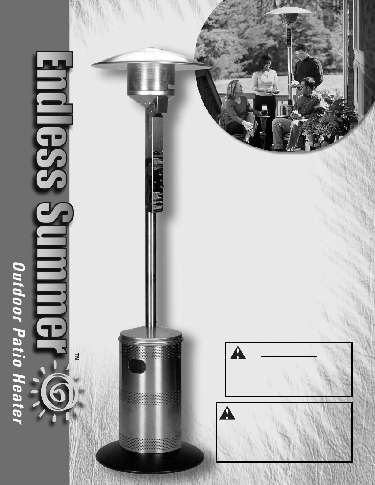
Owner’s Manual
Manuel d’Utilisation
Model No.
163010
W
ARNING
FOR YOUR SAFETY:
For Outdoor Use Only
(outside any enclosure)
A
VER
TISSEMENT
POUR VOTRE SÉCURITÉ:
À utiliser uniquement à
l’exterieur
(hors de tout abri clos)
Page 2
Owner’s manual and assembly instructions: model 163010 natural gas outdoor patio heater 12/4/02
Contact 1-800-762-1142 for assistance.
Do not return to place of purchase.
1
WARNING
FOR YOUR SAFETY:
If you smell gas -
1. Shut off gas to the appliance.
2. Extinguish any open flame.
3. If odor continues, immediately call
your gas supplier or your fire
department.
WARNING
FOR YOUR SAFETY:
• Improper installation, adjustment,
alteration, service or maintenance can
cause injury or property damage.
• Read the installation, operation, and
maintenance instructions thoroughly
before installing or servicing this
equipment.
• Failure to follow the manual’s
warnings and instructions can result
in severe personal injury, death, or
property damage.
• Fuel systems must be installed by
qualified and licensed personnel.
Improper installations present
hazards, which can lead to personal
injury or property damage. Please
contact your local Natural Gas
supplier for these services.
WARNING
FOR YOUR SAFETY:
Do not store or use gasoline or other
flammable vapors and liquids in the
vicinity of this or any other appliance.
WARNING
FOR YOUR SAFETY:
1. Gas leaks may cause a fire or explosion
which can cause serious bodily injury
or death, or damage to property.
2. You must follow all leak-checking
procedures as outlined in step 10
before operating this unit.
3. Never use an open flame to check
for leaks.
WARNING
FOR YOUR SAFETY:
Improper installation, adjustment,
alteration, service or maintenance
can cause injury or property damage.
Read the installation, operation and
maintenance instructions thoroughly
before installing or servicing this
equipment.
WARNING
FOR YOUR SAFETY:
For Outdoor Use Only
(outside any enclosure)
WARNING
FOR YOUR SAFETY:
• Purchaser assumes all risk in the
assembly and operation of this unit.
Failure to follow this manual’s
warnings and instructions can result
in severe personal injury, death or
property damage.
• Do not use in an explosive atmosphere.
Keep heater away from areas where
flammable liquids, gasoline, vapors, or
explosives are stored or used.
Page 3
Owner’s manual and assembly instructions: model 163010 natural gas outdoor patio heater 12/4/02
Contact 1-800-762-1142 for assistance.
Do not return to place of purchase.
2
Save these instructions for
future reference.
If you are assembling this unit
for someone else, give
this manual to him or her to
save for future reference.
Table of Contents
Safety First! . . . . . . . . . . . . . . . . . . . . . . . . . . . . . . . . . . . . . . . . . . . . . . .3
Assembly Instructions
Components & Hardware . . . . . . . . . . . . . . . . . . . . . . . . . . . . . . . . . . .5
General Components & Features . . . . . . . . . . . . . . . . . . . . . . . . . . . .6
Additional Requirements . . . . . . . . . . . . . . . . . . . . . . . . . . . . . . . . . . .6
Step 1 Attach Legs to Base . . . . . . . . . . . . . . . . . . . . . . . . . . . . . . . .6
Step 2 Attach Cylinder Shroud to Legs . . . . . . . . . . . . . . . . . . . . . . . .7
Step 3 Assemble Cup, Plate & Ring to Cap . . . . . . . . . . . . . . . . . . . .7
Step 4 Attach Cap Assembly to Legs/Insert Gas Line . . . . . . . . . . . .7
Step 5 Assemble Emitter Top . . . . . . . . . . . . . . . . . . . . . . . . . . . . . . .8
Step 6 Assemble Emitter . . . . . . . . . . . . . . . . . . . . . . . . . . . . . . . . . . .8
Step 7 Attach Engine to Post . . . . . . . . . . . . . . . . . . . . . . . . . . . . . . .8
Step 8 Connect Engine/Pole Assembly to Cap . . . . . . . . . . . . . . . . . .9
Step 9 Connect Gas Line to Engine . . . . . . . . . . . . . . . . . . . . . . . . . .9
Step 10 Attach Dome to Emitter . . . . . . . . . . . . . . . . . . . . . . . . . . . . .9
Step 11 Secure Gas Line . . . . . . . . . . . . . . . . . . . . . . . . . . . . . . . . .10
Step 12 Check for Leaks . . . . . . . . . . . . . . . . . . . . . . . . . . . . . . . . . .10
Step 13 Install Cylinder Access Panel . . . . . . . . . . . . . . . . . . . . . . .11
Step 14 Replace Engine Access Panel . . . . . . . . . . . . . . . . . . . . . . .11
Operation
Before Turning Gas Supply ON . . . . . . . . . . . . . . . . . . . . . . . . . . . . .12
Before Lighting . . . . . . . . . . . . . . . . . . . . . . . . . . . . . . . . . . . . . . . . . .12
Lighting . . . . . . . . . . . . . . . . . . . . . . . . . . . . . . . . . . . . . . . . . . . . . . . .12
Re-Lighting . . . . . . . . . . . . . . . . . . . . . . . . . . . . . . . . . . . . . . . . . . . . .13
Shutdown . . . . . . . . . . . . . . . . . . . . . . . . . . . . . . . . . . . . . . . . . . . . . .13
Checklist . . . . . . . . . . . . . . . . . . . . . . . . . . . . . . . . . . . . . . . . . . . . . . .14
Troubleshooting . . . . . . . . . . . . . . . . . . . . . . . . . . . . . . . . . . . . . . . . . . .15
Maintenance . . . . . . . . . . . . . . . . . . . . . . . . . . . . . . . . . . . . . . . . . . . . . .16
Storage . . . . . . . . . . . . . . . . . . . . . . . . . . . . . . . . . . . . . . . . . . . . . . . . . .17
Service . . . . . . . . . . . . . . . . . . . . . . . . . . . . . . . . . . . . . . . . . . . . . . . . . .17
Warranty . . . . . . . . . . . . . . . . . . . . . . . . . . . . . . . . . . . . . . . . . . . . . . . . .18
Specifications . . . . . . . . . . . . . . . . . . . . . . . . . . . . . . . . . . . . . . . . . . . . .19
The use and installation of this product must conform to local codes. In
absence of local codes, use the National Fuel and Gas Code, ANSI
Z223.1/NFPA 54, Storage and Handling of Liquefied Petroleum Gases,
ANSI/NFPA 58 or CSA B149.1, Natural Gas and Propane Installation
Code.
Page 4
Owner’s manual and assembly instructions: model 163010 natural gas outdoor patio heater 12/4/02
Contact 1-800-762-1142 for assistance.
Do not return to place of purchase.
3
Safety First!
Installation and repairs should be done by a qualified service person.
Read and become familiar with this entire manual, especially the following
precautions.
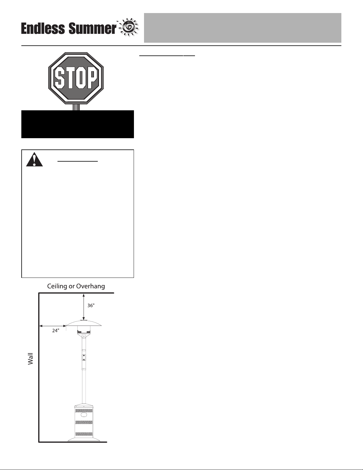
If you are unsure of anything in these instructions, STOP and contact
1-800-762-1142 for assistance.
Caution: This appliance is for outdoor use only (outside any
enclosure). Always make sure there is fresh air ventilation.
• Always maintain at least 36” clearance (top) and 24” clearance (side) from
combustible materials.
• Always place heater on a hard and level surface.
• Do not use if the wind velocity is greater than 10 miles per hour.
• Unit will operate at reduced efficiency below 40º F (5º C).
• It is normal for the heater to make a hissing sound at start-up. This will
decrease as the heater warms up.
• Keep sprinklers and other water sources away from burner and controls.
• Always use extreme caution when near heater. Alert both children and
adults to the hazards of high temperatures, especially to avoid burns or
clothing catching fire.
• Young children and pets should be carefully supervised when they are in
the area of heater.
• Do not hang clothing or other flammable materials either on or near heater.
• Certain materials or items, when stored under heater, will be subjected to
radiant heat and could be seriously damaged.
• Do not alter heater in any manner.
• Inspect heater before each use. If a damaged part is detected, do not
operate until an original equipment replacement part has been properly
installed. Use of unauthorized parts will void warranty and create an
unsafe condition.
• Prior to operating heater, replace any guards or protective devices
removed for servicing.
• During operation, do not touch burner assembly. The surface of heater’s
emitter can reach temperatures approaching 1600ºF.
W
ARNING
FOR YOUR SAFETY:
• Purchaser assumes all risk in
the assembly and operation of
this unit. Failure to follow this
manual’s warnings and
instructions can result in
severe personal injury, death
or property damage.
• Do not use in an explosive
atmosphere. Keep heater away
from areas where flammable
liquids, gasoline, vapors, or
explosives are stored or used.
Before you do anything else,
read and understand all
precautions in Safety First!
Blue
Rhino
Ignitor
Ignitor
Push
Push
Pilot
(Push in)
ON
OFF
Page 5

Owner’s manual and assembly instructions: model 163010 natural gas outdoor patio heater 12/4/02
Contact 1-800-762-1142 for assistance.
Do not return to place of purchase.
4
• After shutdown, do not touch burner assembly until heater has cooled
(approximately 45 minutes after use).
• The appliance and its individual shutoff valve must be disconnected from the
gas supply piping system during any pressure testing of that system at test
pressures in excess of 1/2 psig (3.5 kpa).
• The appliance must be isolated from the gas supply piping system by
closing its individual manual shutoff valve during any pressure testing of the
gas supply piping system at test pressures equal to or less than 1/2 psig
(3.5 kpa).
• Always perform a leak test on gas connections whenever heater is serviced.
Never use a flame to test for leaks. Do not smoke while performing a leak test.
Caution: It is essential to keep the heater’s valve compartment, burners,
and circulating air passages clean.
• Spiders and insects can create a dangerous condition that may damage
heater or make it unsafe. Keep burner area clean of all spiders, webs, or
insects.
• Inspect heater before each use.
• Have heater inspected annually by a qualified service person.
• Check heater immediately if any of the following conditions exist:
• The smell of gas in conjunction with extreme yellow tipping of
burner flames.
• Heater does not reach proper temperature.
Note: At temperatures less than 40º F, heat output will be reduced.
• Heater’s glow is excessively uneven.
• Burner makes popping noises during use.
Note: A slight pop is normal when burner is extinguished.
• Carbon deposits may create a fire hazard. Keep dome and emitter clean at
all times.
• Do not clean heater with combustible or corrosive cleaners. Use warm,
soapy water.
• Do not paint engine, engine access panel or dome.
FOR YOUR SAFETY:
Beware of Spiders
Spiders or small insects can get into
the burner tube or other openings of
your heater, and spin webs or build
nests. These obstructions can lead
to gas flow problems. It is important
to make frequent inspections of
these areas and clean them when
necessary.
Before operating your heater for the
first time, be sure to check for
obstructions that may have occurred
during shipment.
Page 6
Owner’s manual and assembly instructions: model 163010 natural gas outdoor patio heater 12/4/02
Contact 1-800-762-1142 for assistance.
Do not return to place of purchase.
5
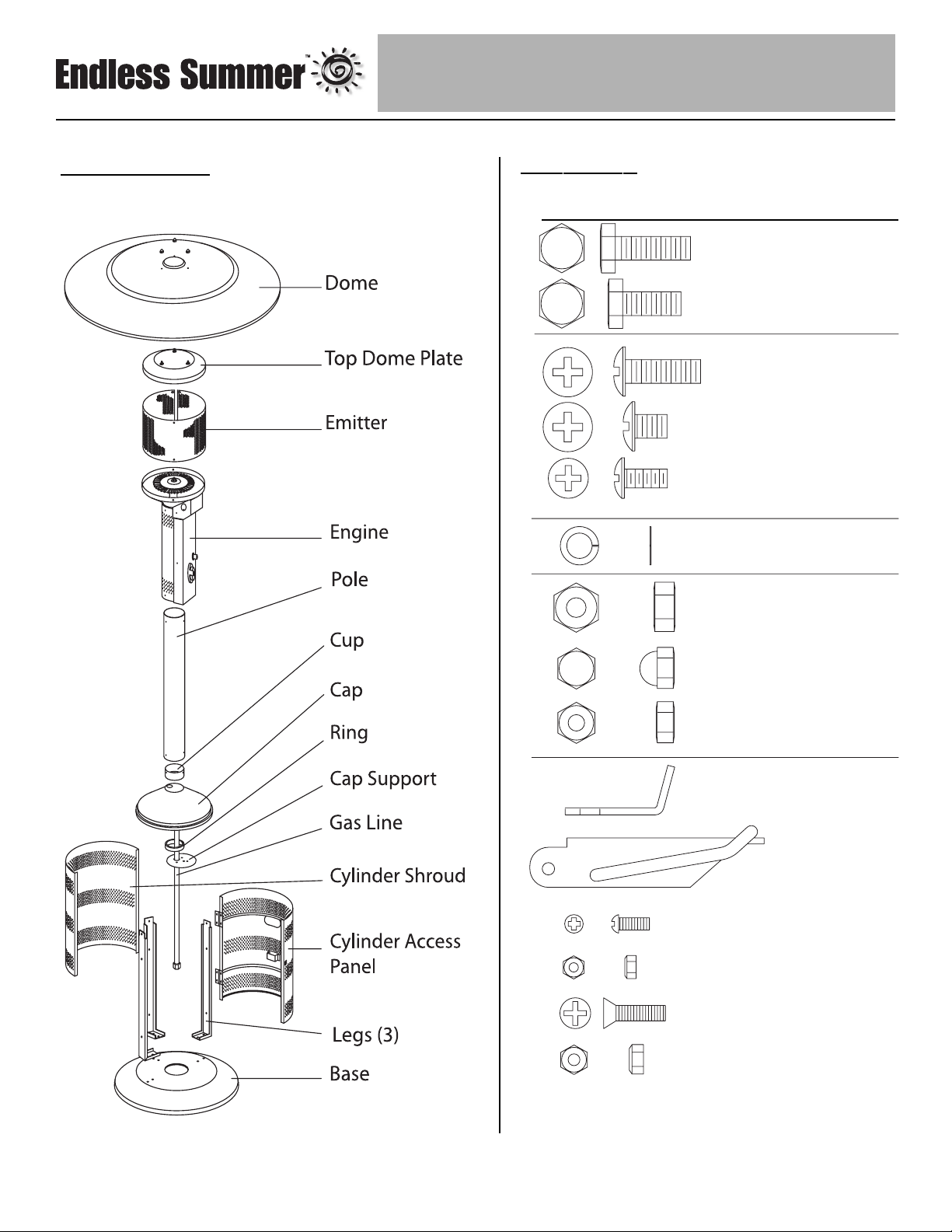
Components
Hardware
Used in
Picture Qty Description Step(s)
9 Large Bolt 1 & 3
3Small Bolt 5
1 Extra Large Screw 11
17 Medium Screw 2, 4, 7 &8
10 Small Screw 6
9 Lockwasher 1 & 5
9 Large Nut 1 & 5
3 Cap Nut 10
2Small Nut 6
1Clip 11
1 Latch 14
2 Latch Screw 14
2 Latch Nut 14
4Hinge Screw 14
4Hinge Nut 14
Page 7
Owner’s manual and assembly instructions: model 163010 natural gas outdoor patio heater 12/4/02
Contact 1-800-762-1142 for assistance.
Do not return to place of purchase.
6
Assembly Instructions
General Components & Features
Familiarize yourself with all components before proceeding. Refer to page 5 for hardware and components, and page 19
for specifications.
Note: All the hardware is in a plastic bag packed in the emitter top inside of a cardboard divider inside the cap. This
also includes the cup and cap support.
Do NOT attempt assembly unless all components are available. If you believe a component is missing or damaged,
contact 1-800-762-1142 for assistance.
Additional Requirements
The following items are not included, but are necessary for the proper assembly of your heater. Do NOT attempt to
assemble without proper tools.
(1) 7/16” Wrench
(1) 7/16” Socket Wrench
(1) #2 Phillips Head Screwdriver
(1) Leak Detection Solution (Instructions to prepare are included in step 13)
Note: You must follow all steps to properly assemble heater.
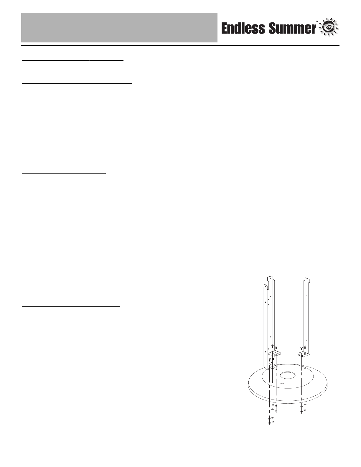
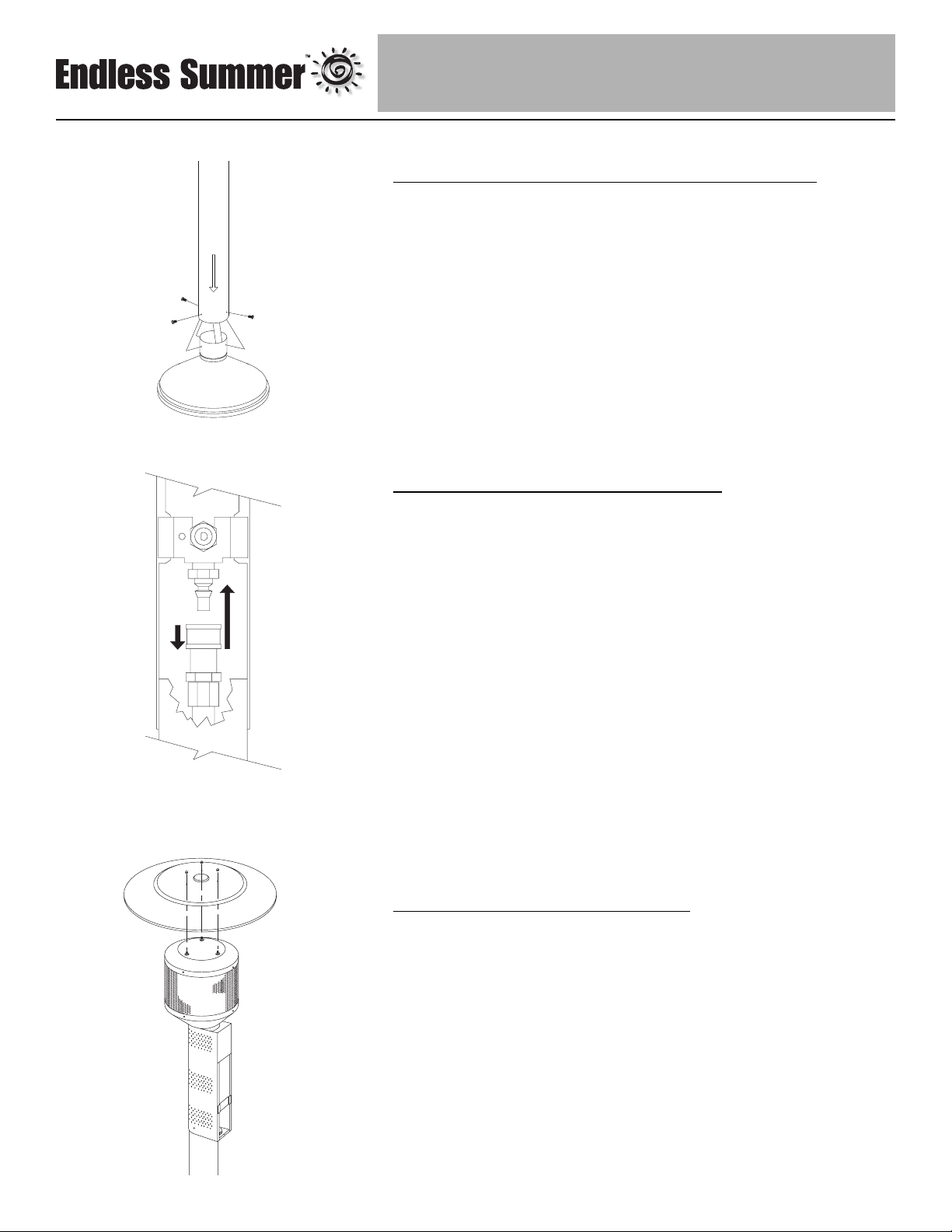
Step 1 – Attach Legs to Base
Note: Attach Leg with notches for hinges as shown at left.
• Secure each leg to base using (2) Large Bolts, (2) Lock Washers
and (2) Large Nuts per leg. Finger tighten only.
• Do not fully tighten until Step 2.
Page 8
Owner’s manual and assembly instructions: model 163010 natural gas outdoor patio heater 12/4/02
Contact 1-800-762-1142 for assistance.
Do not return to place of purchase.
7
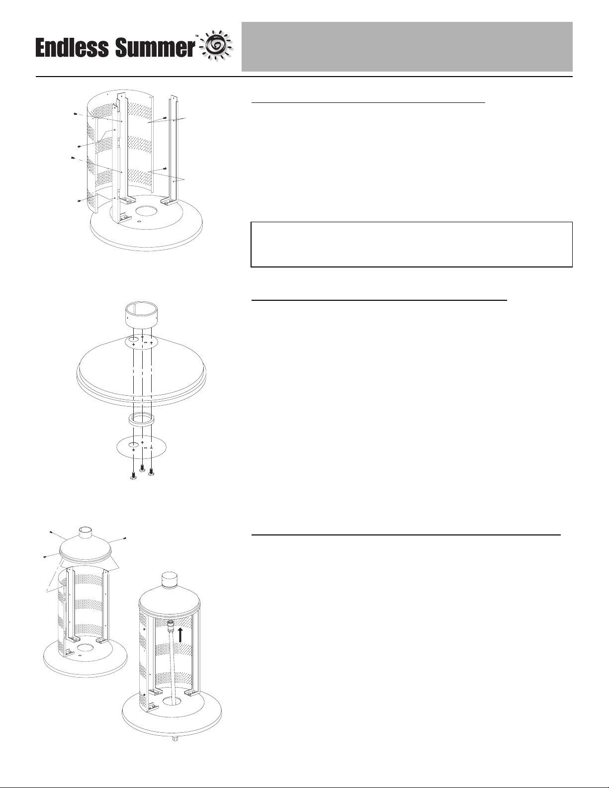
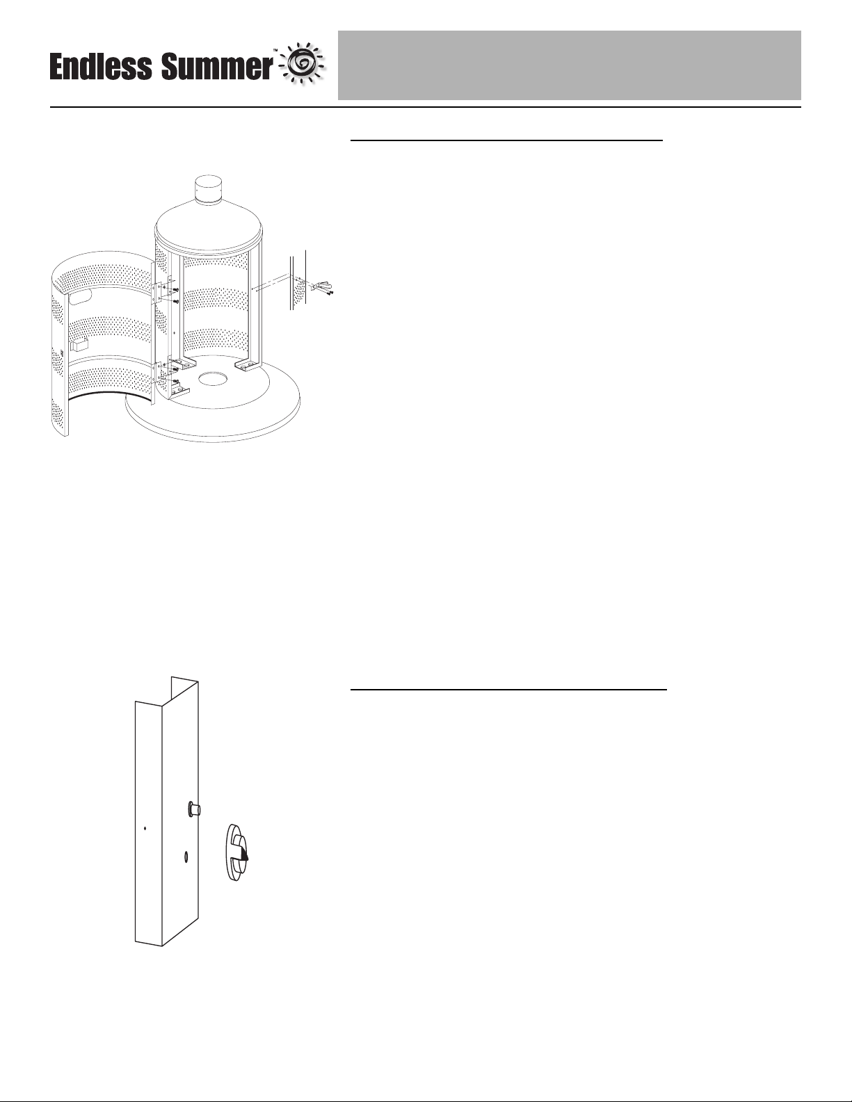
Step 2 – Attach Cylinder Shroud to Legs
• Line up slots in Cylinder Shroud flange with notches in left leg as
shown.
• Line up holes in center of Shroud with holes in Center Leg. Attach
Cylinder Shroud to center Leg using (2) Medium Screws.
• Secure Cylinder Shroud to outside Legs using (2) Medium Screws
per leg.
• Tighten nuts and bolts from Step 1.
Step 3 – Assemble Cup, Plate & Ring to Cap
• Place Spacer Ring on Support Plate so that all holes in plate fit
inside ring.
• Line up 3 small, unthreaded holes in plate with corresponding holes
in cap.
• Line up these holes with three threaded holes in Cup.
• Insert (1) Large Bolt and tighten loosely.
• Repeat for other (2) Large Bolts, then secure all tightly.
Step 4 – Attach Cap Assembly to Legs/Insert Gas Line
• Line up 3 holes in Cap Assembly with holes in top of Shroud
and legs.
• Insert and tighten (1) Medium Screw into center leg.
• Insert and tighten (1) Medium Screw into each of the outer legs.
Tilt base on edge and slide Gas Line up through large hole in Base,
then through Cap Assembly.
TIP:
To tighten use a 7/16” wrench on Bolt and a 7/16” socket wrench on Nut.
Page 9
Owner’s manual and assembly instructions: model 163010 natural gas outdoor patio heater 12/4/02
Contact 1-800-762-1142 for assistance.
Do not return to place of purchase.
8
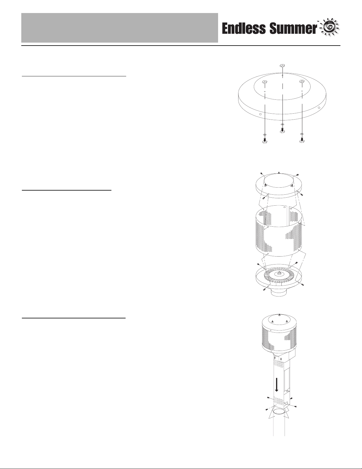
Step 5 – Assemble Emitter Top
• Slip (1) Small Bolt through hole in Emitter Top from inside.
• Slip (1) Lockwasher over bolt and thread (1) Large nut all the way
down and tighten.
• Repeat for other two holes.
Step 6 – Assemble Emitter
• Curl Emitter Screen into a circle. Overlap ends and line up holes.
Secure together using (2) Small screws and (2) small nuts.
• Line up holes in bottom of Emitter Screen with holes in Engine.
• Attach Emitter Screen to Engine with (4) Small Screws.
• Line up holes in top of Emitter Screen with holes in Emitter Top.
• Attach Emitter Screen to Emitter Top with (4) Small Screws.
Step 7 – Attach Engine to Post
• Remove and Save Control Knob.
• Remove and save (3) screws from sides and bottom of Engine
Access Panel.
• Open Engine Access Panel.
• Disconnect wire from Igniter by gently pulling wire.
• Remove and save Engine Access Panel.
• Align threaded holes in Post with holes in bottom of Engine.
• Insert (4) Medium Screws loosely. They will be fully tightened at the
end of the next step.
Note: Do not replace Engine Access Panel until Step 13.
Page 10
Owner’s manual and assembly instructions: model 163010 natural gas outdoor patio heater 12/4/02
Contact 1-800-762-1142 for assistance.
Do not return to place of purchase.
9
Step 8 – Connect Engine/Post Assembly to Cap
• Insert end of Post with (4) holes not threaded over Gas Line
• Line up Post holes with threaded Cap holes.
• Loosely Secure Post to Cap, using (4) Medium Screws, fully tighten
screws in Step 9.
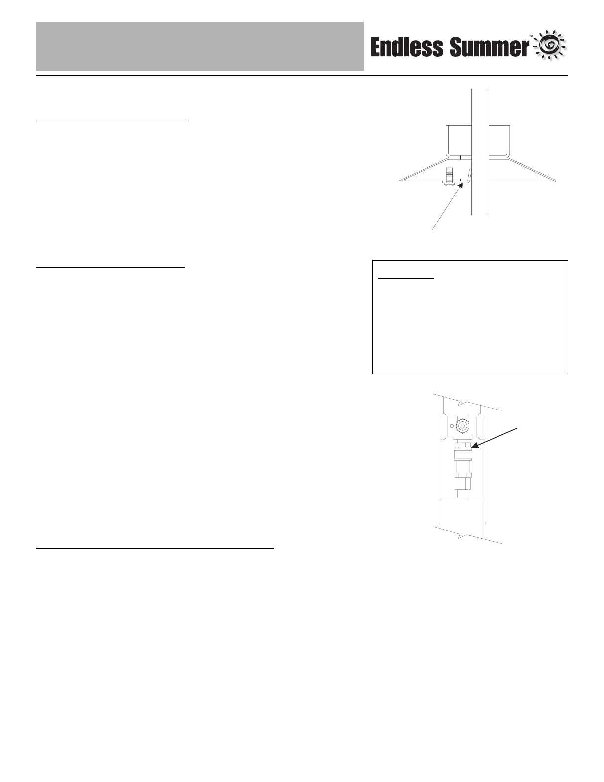
Step 9 – Connect Gas Line to Engine
• To attach Gas Line to Control Valve:
• Pull collar of Gas Line down.
• Insert Gas Line over Control Valve.
• Release Gas Line Collar and it should lock in place. (Tip – push
Gas Line up from bottom of Post to make a good seating before
releasing Collar.)
• Gently tug on line to test for proper connection. If Gas Line moves
you are not properly connected.Do not proceed until a proper
connection has been made.
• After gas line is secure, fully tighten (4) screws from Step 8.
Step 10 – Attach Dome to Emitter
• Gently lay heater on its side
Tip: Use styrofoam end to prop up top half of heater.
• Align holes in Dome with Emitter Studs.
• Secure Dome to Emitter using (3) Cap Nuts.
• Leave heater on its side for next step.
Page 11
Owner’s manual and assembly instructions: model 163010 natural gas outdoor patio heater 12/4/02
Contact 1-800-762-1142 for assistance.
Do not return to place of purchase.
10
Step 11 – Secure Gas Line
• Line up hole in Gas Clip with threaded hole in Support Plate.
• Attach using (1) Extra Long Screw.
• Tighten screw in Gas Line Clip until Gas Line is held securely in place.
• Stand heater upright on base.
Caution:
Your Endless Summer™ Patio Heater
has been checked at all factory
connections for leaks. Recheck all
connections, as movement in shipping
can loosen connections. Check for
leaks even if your unit was assembled
for you at the store.
Step 12 – Check for Leaks
• Make 2-3 oz. of leak check solution by mixing one part liquid
dishwashing soap and three parts water.
• Turn cylinder valve ON.
• Check Gas Line / Control Valve for leaks:
• Spoon several drops of solution onto Gas Line and Control Valve
connection.
• Inspect the solution at the connection to look for bubbles.
• If NO bubbles appear, then the connection is secure.
• If bubbles appear, there is a leak -
• Turn Cylinder valve OFF.
• Loosen screw on Clip.
• Release Gas Line fitting from control valve and re-attach making
sure connection is secure (see Step 9).
• Retighten Clip.
• If you continue to see bubbles after several attempts, contact
1-800-762-1142 for assistance.
Check Gas Line / Cylinder valve for leaks:
• Turn cylinder valve ON.
• Spoon several drops of solution onto Gas Line and Cylinder valve
connection.
• Inspect the solution at the connection to look for bubbles.
• If NO bubbles appear, then the connection is secure.
• If bubbles appear, there is a leak:
• Turn Cylinder valve OFF.
• Release Gas Line fitting from Cylinder valve and re-attach making
sure connection is secure (see Step 13).
• If you continue to see bubbles after several attempts, contact
1-800-762-1142 for assistance.
• Turn Cylinder Valve OFF.
Page 12
Owner’s manual and assembly instructions: model 163010 natural gas outdoor patio heater 12/4/02
Contact 1-800-762-1142 for assistance.
Do not return to place of purchase.
11
Step 13 – Install Cylinder Access Panel
• Line up holes on Latch with slots on Cylinder Shroud. Attach with (2)
Latch Screws and (2) Latch Nuts.
• Line up holes in Access Panel hinges with holes in recessed area of
left leg. Attach each hinge with (2) Hinge Screws and (2) Hinge Nuts.
• Swing Access Panel closed and slip Latch over panel hook and
snap shut.
Step 14 – Replace Engine Access Panel
• Slide Igniter wire onto Igniter post.
• Position Engine Access Panel back in place.
• Secure Panel in place with 3 screws previously removed from side
and bottom holes.
Note: Once you have successfully completed assembly steps 1-15 you
are ready to begin operating your heater.
If you wish to permanently mount your heater to a deck or patio, use the
5/8” hole in the base to attach it to an anchor bolt.
Page 13
Owner’s manual and assembly instructions: model 163010 natural gas outdoor patio heater 12/4/02
Contact 1-800-762-1142 for assistance.
Do not return to place of purchase.
12
Operation
Caution: Do NOT attempt to operate heater until you have read and
understand all precautions in section 1 “Safety First.”
Before Turning Gas Supply ON
• Your heater was designed and approved for outdoor use only. Do
NOT use it inside a building, garage, or any other enclosed area.
• Make sure surrounding areas are free of combustible materials,
gasoline, and other flammable vapors or liquids.
• Ensure that there is no obstruction to air ventilation.
• Be sure all gas connections are tight and there are no leaks.
• Be sure the cylinder cover is clear of debris.
• Be sure any component removed during assembly or servicing are
replaced and fastened prior to starting.
Before Lighting
• Heater should be thoroughly inspected before each use, and by a
qualified service person at least annually.
• If relighting a hot heater, always wait at least 5 minutes.
• Inspect the hose assembly for evidence of excessive abrasion, cuts,
or wear. Suspected areas should be leak tested. If the hose leaks, it
must be replaced prior to operation. Only use the replacement hose
assembly specified by manufacturer.
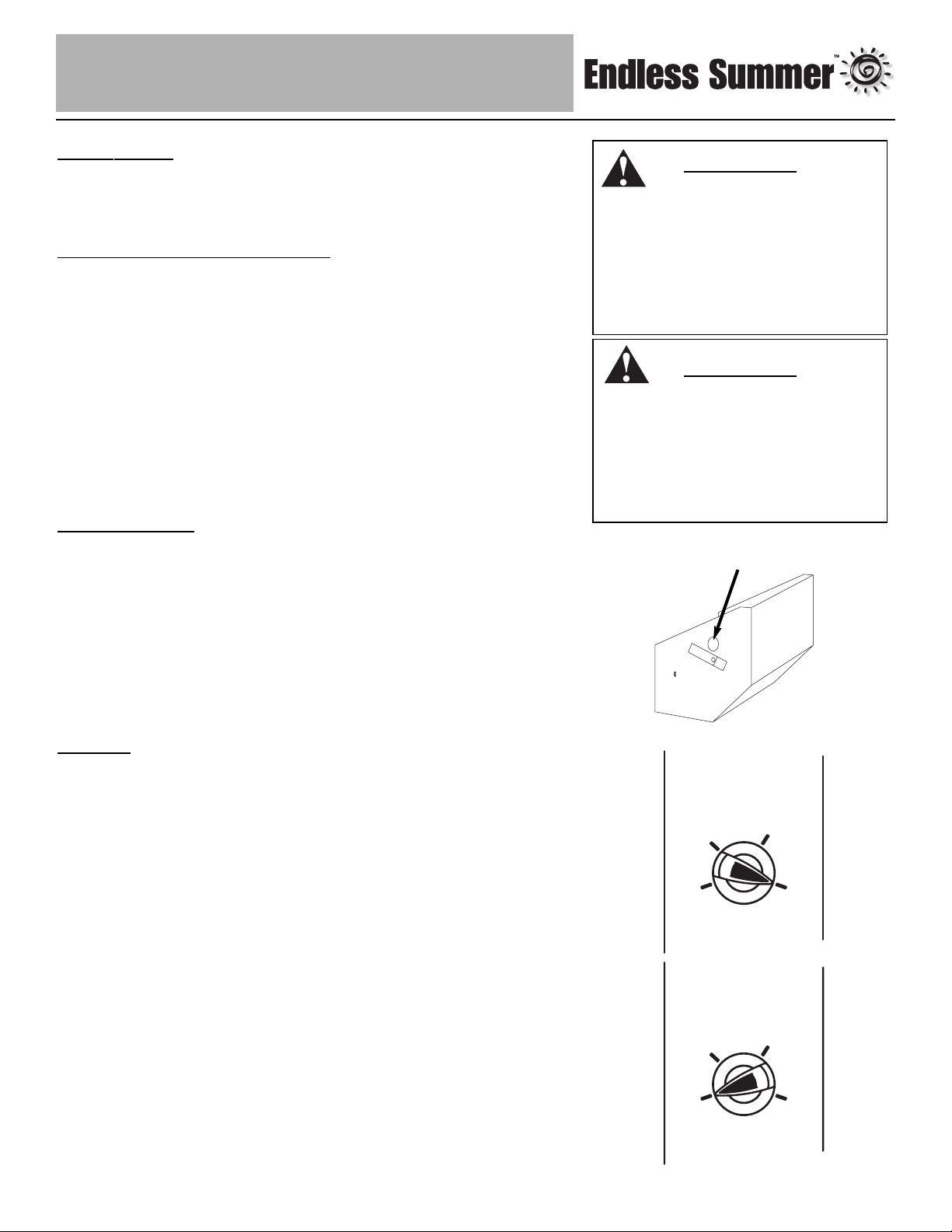
Lighting
Note: This heater is equipped with a Pilot Light that allows for safer
startups and shutdowns. Pilot must be lit before Main Burner can be
started.
• Turn Cylinder Valve OFF.
• Push Control Knob IN and turn to OFF.
• Wait 5 minutes for any gas to clear.
• Turn Cylinder Valve ON.
• Open Viewing Hole by sliding cover to either side.
• Push Control Knob IN and rotate to Pilot position.
• Note - For initial start or after any cylinder change, hold Control Knob
IN for 2 minutes to purge air from gas lines before proceeding.
• Push Igniter button once. Pilot Light flame will appear and be visible
through Viewing Hole.
• Release Control Knob after 30 seconds. Pilot Light will remain lit. If
not, return to step 1.
WARNING
FOR YOUR SAFETY:
If at any time you are unable
to light pilot and smell gas,
wait 5 minutes to allow gas to
dissipate before attempting to
light heater.
WARNING
FOR YOUR SAFETY:
Do NOT touch or move heater for
at least 45 minutes after use.
Allow all burner elements to cool
before touching.
View Hole
LOW
LOW
HIGH
HIGH
LOW
LOW
Pilot
Pilot
(Push in)
Pilot
Pilot
(Push in)
OFF
OFF
HIGH
HIGH
OFF
OFF
Page 14

Owner’s manual and assembly instructions: model 163010 natural gas outdoor patio heater 12/4/02
Contact 1-800-762-1142 for assistance.
Do not return to place of purchase.
13
• Turn Control Knob to ON. Main Burner will light immediately. Flame is
visible through Viewing Hole. If not, return to step 1.
• If for some reason your ignitor fails to deliver a spark, your heater can
be started by inserting a lit match through the pilot view hole while
pushing the control knob in while in the PILOT position.
If you experience any ignition problem consult “Troubleshooting” on
page 15.
Caution: Avoid inhaling fumes emitted from the heater’s first use.
Smoke and odor from the burning of oils used in manufacturing will
appear. Both smoke and odor will dissipate after approximately 30
minutes. The heater should NOT produce thick black smoke.
Note: The burner may be noisy when initially turned on. To eliminate
excessive noise from the burner, turn the Control Knob to the Pilot
position. Then, turn the knob to the level of heat desired.
When heater is ON:
Emitter screen will become bright red due to intense heat. The color is
more visible at night.
Burner will display tongues of blue and yellow flame. These flames
should not be yellow or produce thick black smoke, indicating an
obstruction of airflow through the burners. The flame should be blue
with straight yellow tops.
If excessive yellow flame is detected, turn off heater and consult
“Troubleshooting” on page 15.
Re-lighting
Note: For your safety, Control Knob cannot be turned OFF without first
depressing Control Knob in PILOT position and then rotating it to OFF.
Turn Control Knob to OFF.
Wait at least 10 minutes, to let gas dissipate, before attempting to
relight Pilot.
Repeat the “Lighting” steps on prior page.
Shut Down
Turn Control Knob clockwise to Pilot. (Normally, burner will make a
slight popping sound when extinguished.) Burner will extinguish but
Pilot will remain ON.
To extinguish Pilot, depress Control Knob and continue to turn it
clockwise to OFF.
Turn Cylinder Valve clockwise to OFF and disconnect Regulator when
heater is not in use.
Note: After use, some discoloration of the emitter screen is normal.
W
ARNING
FOR YOUR SAFETY:
Heater will be hot after use. Handle
with extreme care.
WARNING
FOR YOUR SAFETY:
Be careful when attempting to
manually ignite this heater.
Holding in the contrrol know for
more than 10 seconds before
igniting the gas will cause a ball
of flame upon ignition.
Page 15

Owner’s manual and assembly instructions: model 163010 natural gas outdoor patio heater 12/4/02
Contact 1-800-762-1142 for assistance.
Do not return to place of purchase.
14
Operation Checklist
For a safe and pleasurable heating experience, perform this check
before each use.
Before Operating
I am familiar with entire owner’s manual and understand all
precautions noted in “Safety First.”
All components are properly assembled, intact and operable.
No alterations have been made.
All gas connections are secure and do not leak.
Wind velocity is below 10 mph.
Outdoor temperature is greater than 40 degrees F.
Heater is outdoors (outside any enclosure).
There is adequate fresh air ventilation.
Heater is away from gasoline or other flammable liquids or vapors.
Heater is away from windows, air intake openings, sprinklers and
other water sources.
Heater is at least 36” from combustible materials.
Heater is on a hard and level surface.
There are no signs of spider or insect nests.
All burner passages are clear.
All air circulation passages are clear.
Children, pets, clothing, flammable materials and items that can be
damaged from radiant heat are away from the heater.
Children and adults in the area have been alerted to the high
temperature hazards: especially burns and clothing fires.
Children and adults in the area have been warned not to touch
heater near engine during operation and until unit has cooled.
After Operation
Gas control is in OFF position.
Heater is upright in a secure location.
Page 16

Owner’s manual and assembly instructions: model 163010 natural gas outdoor patio heater 12/4/02
Contact 1-800-762-1142 for assistance.
Do not return to place of purchase.
15
Troubleshooting
If the problem is: And this condition exists: Then do this
Pilot won’t light
Note: Heater operates at reduced
efficiency below 40ºF (5ºC)
Gas turned off at source
Blockage in orifice or pilot tube
Air in gas line
Igniter fails
Open valve
Clean or replace orifice or pilot tube
Open gas line and bleed it (pressing
control knob in) for not more than 1 - 2
minutes or until you smell gas
Obtain new igniter and replace
Pilot won’t stay lit
Dirt built up around pilot
Connection between gas valve and
pilot assembly is loose
Thermocouple is not operating
correctly
Clean dirt from around pilot
Tighten connection and perform leak
check
Replace thermocouple
Burner won’t light
Gas pressure is low
Blockage in orifice
Control knob is not in ON position
Have a professional check gas system
Clear blockage
Turn control knob to ON
Burner flame is low
Gas pressure is low
Supply hose is bent or kinked
Control knob fully ON
Have a professional check gas system
Straighten hose
Check burner and orifices for blockage
Emitter glows uneven
Note: Bottom 1” of emitter normally does
NOT glow.
Gas pressure is low
Base is not on a level surface
Heater is level
Have a professional check gas system
Place heater on a level surface
Clean burner
Carbon build-up
Dirt or film on reflector and emitter Clean reflector and emitter
Thick black smoke
Blockage in burner Remove blockage and clean burner
inside and outside
Page 17

Owner’s manual and assembly instructions: model 163010 natural gas outdoor patio heater 12/4/02
Contact 1-800-762-1142 for assistance.
Do not return to place of purchase.
16
Maintenance
To enjoy years of outstanding performance from your heater, make sure you
perform the following maintenance activities on a regular basis:
Keep exterior surfaces clean.
Use warm soapy water for cleaning. Never use flammable or corrosive
cleaning agents.
While cleaning your unit, be sure to keep the area around the burner
and pilot assembly dry at all times. Do not submerge the control
valve assembly. If the gas control is submerged in water, do NOT
use it. It must be replaced.
Air flow must be unobstructed. Keep controls, burner, and circulating air
passageways clean. Signs of possible blockage include:
Gas odor with extreme yellow tipping of flame.
Heater does NOT reach the desired temperature.
Heater glow is excessively uneven.
Heater makes popping noises.
Spiders and insects can nest in burner or orifices. This dangerous condition
can damage heater and render it unsafe for use. Clean burner holes by
using a heavy-duty pipe cleaner. Compressed air may help clear away
smaller particles.
Carbon deposits may create a fire hazard. Clean dome and emitter with
warm soapy water if any carbon deposits develop.
Note: In a salt-air environment (such as near an ocean), corrosion occurs
more quickly than normal. Frequently check for corroded areas and repair
them promptly.
WARNING:
FOR YOUR SAFETY:
• Do NOT touch or move
heater for at least 45 minutes
after use.
• Dome is hot to the touch.
• Allow dome to cool before
touching.
TIP:
Use high-quality automobile wax to help maintain the appearance of your
heater. Apply to exterior surfaces from the pole down. Do not apply to
emitter screen or domes.
Page 18

Owner’s manual and assembly instructions: model 163010 natural gas outdoor patio heater 12/4/02
Contact 1-800-762-1142 for assistance.
Do not return to place of purchase.
17
Storage
Between uses:
Turn Control Knob OFF.
Store heater upright in an area sheltered from direct contact with
inclement weather (such as rain, sleet, hail, snow, dust and debris).
If desired, cover heater to protect exterior surfaces and to help prevent
build up in air passages.
Note: Wait until heater is cool before covering.
During periods of extended inactivity or when transporting:
Turn Control Knob OFF.
Store heater upright in an area sheltered from direct contact with
inclement weather (such as rain, sleet, hail, snow, dust and debris).
If desired, cover heater to protect exterior surfaces and to help prevent
build up in air passages.
Note: Wait until heater is cool before covering.
Service
To learn how to service and procure parts for worn out, defective or damaged
components contact 1-800-762-1142 for assistance or e-mail
customerservice@uniflame.com. Please supply model number and serial ID
number for best service support. These numbers can be found on a label on
the rear of the Valve Housing.
Caution: Use only original equipment replacement parts. Use of
unauthorized parts or modification of parts will void warranty and
create an unsafe condition.
Caution: Always allow heater to cool before attempting service.
Page 19

Owner’s manual and assembly instructions: model 163010 natural gas outdoor patio heater 12/4/02
Contact 1-800-762-1142 for assistance.
Do not return to place of purchase.
18
Warranty
Warranty Period
Heater’s warranty extends for 2 years from date of purchase by original purchaser.
Warranty Terms
Manufactured by UniFlame Corp. 104 Cambridge Plaza Drive, Winston-Salem, NC 27104. 1-800-762-1142.
Manufacturer will cover: All parts found to be defective due to materials or workmanship for 2 year from the date of original purchase.
Proof of purchase is required before warranty performance will be rendered. Sales receipt and validation of product registration are
valid forms of proof of purchase.
Manufacturer will repair or replace parts returned prepaid freight in the U.S.A. at its sole discretion.
There are no other express or implied warranties.
W
arranty Exclusion
Manufacturer will NOT cover:
Assembly or start-up
Normal adjustment to burner
Cleaning and/or general maintenance
Shipping damage
Any misuse which will be determined at the sole discretion of manufacturer
Damage or repairs due to service by an unauthorized agency or the use of unauthorized parts
Improper assembly, such as: no regulator, improper hook-up, etc.
Damage or repairs related to spider or insect nesting
Damage due to weather conditions
W
arranty Procedures
For service or replacement parts, please call 1-800-762-1142 for return authorization and further instructions.
All returns must be sent via prepaid freight.
Legal Rights
No one else is authorized to make any warranties on behalf of manufacturer.
THIS WARRANTY IS IN LIEU OF ANY OTHER WARRANTY, EXPRESS OR IMPLIED, ORAL OR WRITTEN, INCLUDING, BUT NOT
LIMITED TO, ANY WARRANTY OF MERCHANTABILITY OR FITNESS FOR A PARTICULAR PURPOSE.
UNIFLAME SHALL NOT BE LIABLE FOR ANY INCIDENTAL OR CONSEQUENTIAL DAMAGES RESULTING FROM ANY
DEFECTIVE PRODUCT, INCLUDING, BUT NOT LIMITED TO, LOST REVENUE OR PROFITS, BUSINESS INTERRUPTION,
OR ANY LEGAL THEORY UPON WHICH ANY CLAIM MAY BE BASED.
PURCHASER ASSUMES ALL RISK IN THE ASSEMBLY AND OPERATION OF THIS UNIT. FAILURE TO FOLLOW THIS MANUAL’S
WARNINGS AND INSTRUCTIONS CAN RESULT IN SEVERE PERSONAL INJURY, DEATH OR PROPERTY DAMAGE.
Some states do not allow limitations on how long an implied warranty lasts, or the exclusion or limitation relevant to incidental or
consequential damages.
This warranty gives you specific legal rights. You may also have other legal rights which vary from state to state.
Since product improvement is an ongoing process at the manufacturer, we reserve the right to change this product’s
specifications or design without notice.
Page 20

Owner’s manual and assembly instructions: model 163010 natural gas outdoor patio heater 12/4/02
Contact 1-800-762-1142 for assistance.
Do not return to place of purchase.
19
Specifications
Certifications:
CSA International Requirement 5.90
Canadian National Standard CAN1-2.23-M82
Rating:
40,000 BTU/hr. input at 7.0” W.C.
Heat Range:
Up to 20 foot diameter
Fuel:
Natural Gas
Inlet gas supply pressure:
Maximum – 10.5” W.C.
Minimum – 7.0” W.C.
Manifold Pressure:
11.00 in. W.C.
Engine:
IPP E1
Safety Features:
100% Burner shut-off
Manufacturer:
UniFlame Corporation
Made In:
China
Page 21

Owner’s manual and assembly instructions: model 163010 natural gas outdoor patio heater 12/4/02
Contact 1-800-762-1142 for assistance.
Do not return to place of purchase.
20
Page 22

Manuel d’utilisation et instructions de montage: gaz naturel système de chauffage extérieur, modèle 163010 12/4/02
Pour toute assistance appeler le 1-800-762-1142
Ne pas retourner cet appareil au point de vente.
1
AVERTISSEMENT
POUR VOTRE SÉCURITÉ:
À utiliser uniquement à l’extérieur
(hors de tout abri clos)
AVERTISSEMENT
POUR VOTRE SÉCURITÉ:
En cas d’odeur de gaz -
1. Fermez le robinet de gaz alimentant
l’appareil.
2. Éteignez toute flamme.
3. Si l’odeur persiste, contactez votre
fournisseur de gaz ou les pompiers.
AVERTISSEMENT
POUR VOTRE SÉCURITÉ:
1. Toute fuite de gaz risque de provoquer
un incendie ou une explosion et
entraîner des dégâts matériels, des
blessures graves voire mortelles.
2. Respectez toutes les consignes de
l’étape 13 avant d’utiliser l’appareil.
3. Ne jamais utiliser de flamme nue afin
de détecter une fuite.
AVERTISSEMENT
POUR VOTRE SÉCURITÉ:
Ne pas utiliser ni stocker d’essence ou de
liquides et autres vapeurs inflammables à
proximité de cet appareil ou de tout autre
appareil.
AVERTISSEMENT
POUR VOTRE SÉCURITÉ:
• Toute installation défectueuse ou
modification incorrecte ainsi que tout
mauvais réglage ou entretien incorrect
risque d’entraîner des blessures ou des
dégâts matériels.
• Lire complètement les instructions
d’installation, d’utilisation et d’entretien
avant de monter l’appareil ou de
procéder à son entretien.
• Le manque de suivre la mort les
avertissements du manuel et des
instructions peut avoir comme
conséquence des blessures, ou les
dégats matériels graves.
• Des installations carburant doivent être
installées par le personnel qualifié et
autorisé. Les installations inexactes
présentent les risques, qui peuvent
mener aux blessures ou aux dégats
matériels. Veuillez contacter votre
fournisseur local de gaz naturel pour
ces services.
A
VERTISSEMENT
POUR VOTRE SÉCURITÉ:
• L'acheteur assume tous les risques lors de
l’assemblage et de l’utilisation de cet
appareil. Le non-respect des instructions
et des consignes de sécurité de ce manuel
risque de provoquer des blessures graves
voire mortelles ou des dégâts matériels.
• Ne pas utiliser l'appareil dans une
atmosphère explosive. Conservez
l'appareil à l'écart de toute zone où des
liquides inflammables ou de l'essence sont
remisés ou stockés et où des vapeurs ou
émanations explosives sont présentes.
AVERTISSEMENT
POUR VOTRE SÉCURITÉ:
Toute installation défectueuse ou
modification incorrecte ainsi que tout
mauvais réglage ou entretien incorrect
risque d’entraîner des blessures ou des
dégâts matériels. Lire complètement les
instructions d’installation, d’utilisation et
d’entretien avant de monter l’appareil ou
de procéder à son entretien.
Page 23

Manuel d’utilisation et instructions de montage: gaz naturel système de chauffage extérieur, modèle 163010 12/4/02
Pour toute assistance appeler le 1-800-762-1142
Ne pas retourner cet appareil au point de vente.
2
Table des matières
La Sécurité avant tout! . . . . . . . . . . . . . . . . . . . . . . . . . . . . . . . . . . . . . . . . . . . .3
Instructions de montage
Pièces et quincaillerie . . . . . . . . . . . . . . . . . . . . . . . . . . . . . . . . . . . . . . . . . .5
Pièces et caractéristiques générales . . . . . . . . . . . . . . . . . . . . . . . . . . . . . . 6
Accessoires supplémentaires . . . . . . . . . . . . . . . . . . . . . . . . . . . . . . . . . . .6
Étape 1 Fixer les jambes au socle . . . . . . . . . . . . . . . . . . . . . . . . . . . . . . .6
Étape 2 Fixer le dispositif protecteur de la bonbonne aux jambes . . . . . . .7
Étape 3 Fixer la coupelle, la plaque et l’anneau au chapeau de carénage 7
Étape 4 Fixer le chapeau aux jambes /
Introduire la conduite de gaz . . . . . . . . . . . . . . . . . . . . . . . . . . . . .7
Étape 5 Assembler la partie supérieure de l’émetteur . . . . . . . . . . . . . . . .8
Étape 6 Assembler l’émetteur . . . . . . . . . . . . . . . . . . . . . . . . . . . . . . . . . . .8
Étape 7 Fixer le moteur au pôle . . . . . . . . . . . . . . . . . . . . . . . . . . . . . . . . .8
Étape 8 Raccorder l’ensemble moteur/pôle au chapeau de carénage . . . .9
Étape 9 Raccorder la conduite de gaz au moteur . . . . . . . . . . . . . . . . . . .9
Étape 10 Fixer le dôme à l’émetteur . . . . . . . . . . . . . . . . . . . . . . . . . . . .10
Étape 11 Raccorder la conduite de gaz . . . . . . . . . . . . . . . . . . . . . . . . . .10
Étape 12 Rechercher une fuite potentielle . . . . . . . . . . . . . . . . . . . . . . . .10
Étape 13 Installer le panneau d’accès de la bonbonne . . . . . . . . . . . . . .11
Étape 14 Replacer le panneau d’accès du moteur . . . . . . . . . . . . . . . . .11
Fonctionnement
Avant d’amorcer l’alimentation de gaz (ON) . . . . . . . . . . . . . . . . . . . . . . .12
Avant d’allumer . . . . . . . . . . . . . . . . . . . . . . . . . . . . . . . . . . . . . . . . . . . . .12
Allumer . . . . . . . . . . . . . . . . . . . . . . . . . . . . . . . . . . . . . . . . . . . . . . . . . . . .12
Rallumer . . . . . . . . . . . . . . . . . . . . . . . . . . . . . . . . . . . . . . . . . . . . . . . . . .13
Éteindre . . . . . . . . . . . . . . . . . . . . . . . . . . . . . . . . . . . . . . . . . . . . . . . . . . .13
Liste de vérifications à effectuer avant toute utilisation . . . . . . . . . . . . . . .14
Guide de dépannage . . . . . . . . . . . . . . . . . . . . . . . . . . . . . . . . . . . . . . . . . . . .15
Entretien . . . . . . . . . . . . . . . . . . . . . . . . . . . . . . . . . . . . . . . . . . . . . . . . . . . . . .16
Rangement . . . . . . . . . . . . . . . . . . . . . . . . . . . . . . . . . . . . . . . . . . . . . . . . . . . .17
Service après-vente . . . . . . . . . . . . . . . . . . . . . . . . . . . . . . . . . . . . . . . . . . . . .17
Garantie . . . . . . . . . . . . . . . . . . . . . . . . . . . . . . . . . . . . . . . . . . . . . . . . . . . . . .18
Caractéristiques techniques . . . . . . . . . . . . . . . . . . . . . . . . . . . . . . . . . . . . . . .19
L'utilisation et l'installation de ce produit doivent se conformer aux codes locaux.
En l'absence des codes locaux, employez le code national de carburant et de
gaz, la norme ANSI Z223.1/NFPA 54, le stockage et la manipulation des gaz de
petrole liquifies, ANSI/NFPA 58 ou CSA B149.1, gaz naturel et code
d'installation de propane.
Conservez ces instructions afin
de pouvoir les consulter
ultérieurement. Si vous êtes en
train d’assembler cet
appareil pour une autre
personne, veuillez lui fournir le
manuel afin qu'elle puisse le
consulter plus tard.
Page 24

Manuel d’utilisation et instructions de montage: gaz naturel système de chauffage extérieur, modèle 163010 12/4/02
Pour toute assistance appeler le 1-800-762-1142
Ne pas retourner cet appareil au point de vente.
3
La sécurité avant tout!
Lisez et familiarisez-vous avec ce manuel et surtout les précautions suivantes.
Si vous avez des questions concernant ces instructions, ARRÊTEZ et
composez le 1-800-762-1142 pour toute assistance.
Attention: cet appareil est sensé être utilisé à l'extérieur uniquement (hors
de tout abri). Assurez-vous qu'il y ait toujours suffisamment d'air pour la
ventilation de l'appareil.
• Veillez à ce qu'il y ait toujours un espace d'au moins 91 cm au-dessus et de 61
cm sur les côtés entre l'appareil et toute matière combustible.
• Veillez à ce que l'appareil soit toujours placé sur une surface dure et plane.
• N’utilisez pas l'appareil si la vitesse du vent dépasse 16 km/h.
• Si la température descend en dessous de 40ºF (5ºC), l'appareil fonctionnera à
un rendement moindre.
• Conservez les arroseurs automatiques et autres sources d'eau à l'écart des
brûleurs et des commandes.
• Faites preuve d'une extrême précaution lorsque vous êtes à proximité de
l'appareil. Indiquez aux enfants et aux adultes les dangers existants en
raison des hautes températures afin d'éviter qu'ils ne se brûlent ou que
leurs vêtements ne prennent feu.
• Ne laissez jamais les enfants et les animaux domestiques sans
surveillance lorsque ces derniers sont à proximité de l'appareil.
• Ne pendez pas de vêtements ou d'autres matières inflammables sur
l'appareil ou à proximité de ce dernier.
• Tout cache ou dispositif de protection ayant été retiré afin de procéder à
une réparation ou à l'entretien de l'appareil, doit être remis en place avant
de mettre en marche l'appareil.
• Certains matériaux ou articles risquent d'être sérieusement endommagés en
raison de la chaleur rayonnante si ces derniers sont placés sous l'appareil.
• Ne modifiez en aucune façon l'appareil.
• Utilisez uniquement le régulateur de pression et les tuyaux fournis avec
l’appareil. De plus, les pièces et accessoires de rechange utilisés doivent être
ceux spécifiés par le fabricant.
• Vérifiez l'appareil avant toute utilisation. Si vous détectez une pièce
endommagée, n'utilisez pas l'appareil avant d'installer une pièce d'origine.
L'utilisation de toute pièce non approuvée par le fabricant annulera la garantie et
présentera un danger.
• Ne tentez pas d'utiliser l'appareil sans un régulateur de gaz en état de
fonctionnement et ayant été monté à l'usine. Si le régulateur s'avère
endommagé, utilisez uniquement un régulateur de rechange fourni par l'usine.
• Ne touchez pas les pièces du brûleur lorsque l'appareil fonctionne. La surface
de l'émetteur de chaleur peut atteindre 1600ºF (870ºC).
• Après avoir éteint l'appareil, ne touchez pas le brûleur jusqu'à ce que l'appareil
se soit refroidi (attendre environ 45 minutes).
Avis: cet appareil ne doit pas être utilisé avec un carburant autre que du propane
liquide. Le non-respect de cette consigne nuira au rendement de l'appareil et
annulera la garantie.
Avant de faire quoi que ce soit,
veuillez lire et comprendre
toutes les consignes de la
section “La sécurité avant tout!”
AVERTISSEMENT
POUR VOTRE SÉCURITÉ:
•
L'acheteur assume tous les
risques lors de l’assemblage et
de l’utilisation de cet appareil.
Le non-respect des instructions
et des consignes de sécurité de
ce manuel risque de provoquer
des blessures graves voir la mort
ou des dégâts matériels.
• Ne pas utiliser l'appareil dans une
atmosphère explosive. Conservez
l'appareil à l'écart de toute zone
où des liquides inflammables ou
de l'essence sont remisés ou
stockés et où des vapeurs ou
émanations explosives sont
présentes.
Plafond ou surplomb
91 cm
61 cm
Mur
Blue
Rhino
Ignitor
Ignitor
Push
Push
Pilot
(Push in)
ON
OFF
Page 25

Manuel d’utilisation et instructions de montage: gaz naturel système de chauffage extérieur, modèle 163010 12/4/02
Pour toute assistance appeler le 1-800-762-1142
Ne pas retourner cet appareil au point de vente.
4
Bonbonne de gaz de 9 kg
Valve
45-48 cm
Collier
Corps
Socle
POUR VOTRE SÉCURITÉ:
Attention aux araignées
Les araignées et autres insectes
peuvent s'introduire dans la
tubulure du brûleur et les autres
orifices de l'appareil et pendre
leurs toiles et y fabriquer leurs
nids. Ces obstacles risquent de
provoquer des problèmes au
niveau de l'alimentation du gaz.
Vérifiez fréquemment ces endroits
et nettoyez-les si nécessaire.
Avant d'utiliser l'appareil pour la
première fois, vérifiez qu'aucun
obstacle de ce genre n'est apparu
lors du transport.
V
ous avez besoin d'une
bonbonne de gaz?
Essayez le service de
bonbonnes de rechange Blue
Rhino. C'est un service facile,
rapide, sans danger et présent
dans des dizaines de milliers de
points de vente partout dans le
pays. Achetez une bonbonne
neuve ou échangez votre
bonbonne vide contre une
bonbonne déjà remplie.
Pour le point de vente le plus
proche consultez
www.bluerhino.com.
Attention: le propane liquide (LP) est un gaz inflammable et dangereux si
ce dernier n'est pas manipulé correctement. Soyez conscient des dangers
avant d'utiliser tout appareil fonctionnant au propane.
• Caractéristiques du propane: le propane est un gaz inflammable qui risque
d'exploser sous pression. C'est un gaz plus lourd que l'air présent en gisements
dans les régions basses.
• À l'état naturel, le propane est inodore. Pour votre sécurité, un odorisant ayant
l'odeur de choux avariés a été ajouté.
• Tout contact avec la peau risque d'entraîner des brûlures.
• Cet appareil est expédié de l'usine afin d'être utilisé avec du propane
uniquement.
• Utilisez uniquement des bonbonnes de gaz de 20 lbs (9 kg) homologuées par le
DOT (Ministère des Transports) (il s'agit des mêmes bouteilles que celles
utilisées pour les grils à gaz) avec soupape de sécurité QCC Acme/Type 1. Ces
valves sont faciles à identifier car elles possèdent un filetage interne et externe.
• N'utilisez jamais une bonbonne de propane si le corps, la commande, le col ou
le socle est endommagé.
• Toute bonbonne de propane bosselée ou rouillée présente un risque et devrait
être vérifiée par votre fournisseur de bouteilles de gaz.
• Le système d’alimentation de la bonbonne de gaz doit être homologué pour
l’extraction des vapeurs de gaz.
• La bonbonne doit posséder un col assurant la protection de la valve.
• Lorsque vous n'utilisez pas l'appareil, fermez la commande de gaz de la
bonbonne (OFF).
• Veillez à toujours effectuer un test afin de rechercher toute fuite potentielle au
niveau des raccords de gaz. N'utilisez jamais de flamme nue afin de rechercher
une fuite. Ne fumez jamais lorsque vous effectuez le test.
• Attention: il est primordial que le compartiment de la valve de l'appareil,
les brûleurs et les passages par où l'air circule demeurent propres.
• Les araignées et les insectes risquent de provoquer des conditions dangereuses
et de nuire au bon fonctionnement de l'appareil. Veillez à ce que la zone du
brûleur demeure propre et sans toiles d'araignées ou insectes.
• Vérifiez l'appareil avant chaque utilisation.
• Faites en sorte qu'un réparateur agréé inspecte l'appareil une fois par an.
• Vérifiez immédiatement l'appareil dans les cas suivants:
• Vous sentez une odeur de gaz et les crêtes des flammes sont extrêmement
jaunes.
• L'appareil n'atteint pas la température adéquate. Remarque: l'appareil
fonctionnera à un rendement moindre à une température extérieure
inférieure à 40ºF (5ºC).
• La lueur de chauffage n'est pas du tout uniforme.
• Le brûleur fait du bruit lorsqu'il fonctionne. Remarque: il est normal que le
brûleur émette un léger bruit lors de son extinction.
• Des résidus de carbone risquent de provoquer un incendie. Veillez à ce que le
dôme et l'émetteur demeurent toujours propres.
• Ne nettoyez pas l'appareil avec un nettoyant combustible ou corrosif. Utilisez de
l'eau tiède savonneuse.
• Ne peignez pas le moteur, le panneau d’accès au moteur ni le dôme.
Page 26

Manuel d’utilisation et instructions de montage: gaz naturel système de chauffage extérieur, modèle 163010 12/4/02
Pour toute assistance appeler le 1-800-762-1142
Ne pas retourner cet appareil au point de vente.
5
Pièces
Quincaillerie
Utilisé à
Dessin Qté Description l’étape(s)
9Grand boulon 1 & 3
3 Petit boulon 5
1Vis extra grande 11
17 Vis taille moyenne 2, 4, 7 & 8
10 Petite vis 6
9Rondelle de blocage 1 & 5
9Grand écrou 1 & 5
3 Écrou borgne 10
2Petit écrou 6
1 Bride de serrage 11
1Verrou 14
2Vis du verrou 14
2 Écrou du verrou 14
4Vis de charnière 14
4 Écrou de charnière 14
Dôme
Plaque du dome
supérieur
Émetteur de
chaleur
Moteur
Pôle
Coupelle
Chapeau de
carénage
Anneau
Support du
chapeau
Lignede gaz
Protecteur de la
bonbonne de gaz
Panneau d’accès à
la bonbonne
Jambes (3)
Socle
Page 27

Manuel d’utilisation et instructions de montage: gaz naturel système de chauffage extérieur, modèle 163010 12/4/02
Pour toute assistance appeler le 1-800-762-1142
Ne pas retourner cet appareil au point de vente.
6
Instructions de montage
Pièces et caractéristiques générales
Familiarisez-vous avec toutes les pièces avant de commencer. Reportez-vous à la page 5 pour les pièces et articles de
quincaillerie et à la page 19 pour les caractéristiques techniques de l’appareil.
NE PAS tenter de monter l'appareil si vous n'avez pas toutes les pièces. Si vous pensez que des pièces sont
manquantes ou endommagées, appelez le 1-800-762-1142.
Remarque: toutes les pièces de quincaillerie sont fournies fixées au dos d’une fiche de carton et numérotées afin de les
faire correspondre aux diverses étapes du montage.
Accessoires Supplémentaires
Les articles suivants ne sont pas inclus mais nécessaires pour obtenir un assemblage adéquat de votre radiateur. Ne
procédez PAS à l’assemblage, sans avoir sous la main les outils appropriés.
(1) Clé 7/16” (11 mm)
(1) Clé à douille 7/16” (11 mm)
(1) Tournevis à tête Phillips # 2
(1) Solution de détection de fuites (Les instructions pour préparer la solution sont incluses dans l’étape 13).
Remarque: vous devez suivre toutes les étapes pour assembler correctement l’appareil.
Étape 1 – Fixer les jambes au socle
Remarque: fixez la jambe munie d’encoches pour charnières comme
illustré à gauche.
• Fixez chacune des jambes au socle, à l’aide de (2) grands boulons,
(2) grandes rondelles de blocage et (2) grands écrous par jambe.
Resserrez à la main seulement.
• Assurez-vous de ne pas resserrer ces pièces avant l’étape 2.
Page 28

Manuel d’utilisation et instructions de montage: gaz naturel système de chauffage extérieur, modèle 163010 12/4/02
Pour toute assistance appeler le 1-800-762-1142
Ne pas retourner cet appareil au point de vente.
7
Étape 2 – Fixer le dispositif protecteur de la bonbonne
aux jambes
• Alignez les rainures de la plaque de protection de la bonbonne aux
encoches de la jambe gauche en vous reportant à l’illustration.
• Alignez les orifices situés dans le centre du dispositif protecteur aux
orifices de la jambe centrale. Fixez le carénage de la bonbonne à la
jambe centrale, à l’aide de (2) vis moyennes.
• Fixez le dispositif protecteur de la bonbonne aux jambes extérieures,
à l’aide de (2) vis moyennes sur chaque jambe.
• Resserrez les écrous et les boulons de l’étape 1.
CONSEIL:
Pour resserrer, utilisez une clé de 7/16” (11 mm) sur le boulon et
une clé à douille de 7/16” (11 mm) sur l’écrou.
Étape 3 – Fixer la coupelle, la plaque et l’anneau au
chapeau de carénage
• Placez l’anneau d’espacement sur la plaque de support, de façon à
ce que les orifices puissent être installés à l’intérieur de l’anneau.
• Alignez les 3 petits orifices non filetés de la plaque aux orifices
correspondants du chapeau.
• Alignez ces orifices aux trois orifices filetés du carénage.
• Insérez (1) grand boulon et resserrez-le légèrement.
• Répétez pour les (2) autres grands boulons et par la suite,
resserrez-les fermement.
Étape 4 – Fixer le chapeau de carénage aux jambes /
Introduire la conduite de gaz
• Alignez 3 orifices du chapeau de carénage aux orifices situés dans
la partie supérieure du dispositif protecteur et des jambes.
• Insérez et resserrez (1) vis moyenne dans la jambe centrale.
• Insérez et resserrez (1) vis moyenne dans chacune des jambes
extérieures.
• Inclinez le socle sur son rebord et glissez la conduite de gaz vers le
haut à travers le grand orifice dans le socle et ensuite par le
chapeau de carénage.
Page 29

Manuel d’utilisation et instructions de montage: gaz naturel système de chauffage extérieur, modèle 163010 12/4/02
Pour toute assistance appeler le 1-800-762-1142
Ne pas retourner cet appareil au point de vente.
8
Étape 6 – Assembler l’émetteur
• Enroulez la grille de l’émetteur afin d’en faire un cercle. Faites en
sorte que les bouts se chevauchent et alignez les trous. Fixez la
grille en utilisant (2) petites vis et (2) petits écrous.
• Alignez les trous du bas de la grille de l’émetteur avec les trous du
moteur.
• Fixez la grille de l’émetteur au moteur en utilisant (4) petites vis.
• Alignez les trous du haut de la grille de l’émetteur avec les trous de
la partie supérieure de l’émetteur.
• Fixez la grille à la partie supérieure de l’émetteur en utilisant (4)
petites vis.
Étape 5 – Assembler la partie supérieure de l’émetteur /
Fixer le pôle au socle
• Glissez (1) petit boulon et introduisez-le à travers l’orifice de la partie
supérieure de l’émetteur, à partir de l’intérieur.
• Glissez (1) rondelle de blocage par-dessus le boulon et insérez (1)
grand écrou jusqu’au fond et sserrez-le.
• Répétez l’opération pour les deux autres orifices.
Étape 7 - Fixer le moteur au pôle
• Retirez et conservez le bouton de contrôle.
• Retirez et conservez les (3) vis, situées sur les côtés et la partie
inférieure du panneau d’accès du moteur.
• Déconnectez le fil d’amorçage, en le tirant légèrement.
• Retirez et réservez le panneau d’accès du moteur.
• Alignez les orifices du pôle, aux orifices situés à la partie inférieure
du moteur.
• Insérez (4) vis moyennes sans les resserrer. Elles devront être
resserrées complètement à la fin de la prochaine étape.
Remarque: ne pas replacer le panneau d’accès du moteur, avant
l’étape 13.
Page 30

Manuel d’utilisation et instructions de montage: gaz naturel système de chauffage extérieur, modèle 163010 12/4/02
Pour toute assistance appeler le 1-800-762-1142
Ne pas retourner cet appareil au point de vente.
9
Étape 8 - Raccorder l’ensemble moteur/pôle au chapeau
de carénage
• Insérez l’extrémité du pôle possédant (4) orifices non filetés, pardessus la conduite de gaz.
• Alignez les orifices du montant aux orifices filetés du capuchon.
• Fixez légèrement le montant au chapeau à l’aide de (4) vis de taille
moyenne. Serrez ces vis complètement lors de l’étape 9.
Étape 9 – Raccorder la conduite de gaz au moteur
• Raccordez la conduite de gaz à la valve de commande.
• Tirez sur le col de la conduite de gaz.
• Introduisez la conduite de gaz par-dessus la valve de commande
• Relâchez le col et il devrait se bloquer en place. (Conseil: poussez
vers le haut sur la conduite de gaz à partir du bas du montant afin que
l'appui soit adéquat lorsque vous relâchez le col.)
• Tirez doucement sur la conduite afin de vérifier que le raccord a été
effectué correctement. Si la conduite de gaz bouge, le raccord a mal
été effectué. Recommencez l'opération jusqu'à ce que le raccord soit
parfait.
• Après avoir raccordé la conduite de gaz, serrez complètement les (4)
vis de l'étape 8.
Étape 10 - Fixer le dôme à l’émetteur
• Placez doucement l’appareil sur le côté.
• Conseil: placez l'appareil afin qu'il repose sur le côté en utilisant un
morceau de l'emballage en mousse de polystyrène afin de surélever
la partie supérieure.
• Alignez les orifices du dôme aux tiges filetées de l’émetteur.
• Fixez le dôme à l’émetteur, à l’aide de (3) écrous borgnes.
• Maintenez l’appareil sur le côté, pour la prochaine étape.
Page 31

Manuel d’utilisation et instructions de montage: gaz naturel système de chauffage extérieur, modèle 163010 12/4/02
Pour toute assistance appeler le 1-800-762-1142
Ne pas retourner cet appareil au point de vente.
10
Étape 11 - Fixer la conduite de gaz
• Alignez l’orifice de la bride de serrage destiné à la conduite de gaz à
l’orifice fileté de la plaque de support.
• Fixez l’ensemble sans resserrer en utilisant (1) vis extra longue
• Resserrez la vis de la bride de la conduite de gaz jusqu’à ce que la
conduite de gaz soit fixée solidement en place.
• Replacez l’appareil en position verticale sur le socle.
Étape 15 – Rechercher une fuite potentielle
• Préparez une solution d’environ 80 ml destinée à détecter les fuites en
mélangeant un volume de détergent à vaisselle et 3 volumes d'eau.
• Ouvrez la valve de la bonbonne de gaz (ON).
• Vérifiez que la conduite de gaz et la valve de commande ne
présentent pas de fuites:
• À l'aide d'une cuillère, versez quelques gouttes de la solution sur le
raccord de la conduite de gaz et de la valve de commande.
• Vérifiez si des bulles apparaissent au niveau des raccords
• Si les raccords NE présentent PAS de bulles, le raccord est étanche.
• Si des bulles apparaissent, vous venez de découvrir une fuite :
• Fermez la valve de la bonbonne de gaz (OFF).
• Desserrez la vis de la bride.
• Desserrez la pièce de raccord retenant la conduite de gaz à la
bonbonne et effectuez à nouveau le raccord en vous assurant que
le raccord est étanche (voir étape 9).
• Serrez à nouveau la bride.
• Si des bulles persistent après plusieurs tentatives, composez le
1-800-762-1142.
Vérifier la conduite de gaz et la bonbonne:
• Ouvrez la valve de la bonbonne de gaz (ON).
• À l'aide d'une cuillère, versez quelques gouttes de la solution sur le
raccord de la conduite et de la valve de la bonbonne.
• Vérifiez si des bulles apparaissent au niveau des raccords
• Si les raccords NE présentent PAS de bulles, le raccord est étanche.
• Si des bulles apparaissent, vous venez de découvrir une fuite :
• Fermez la valve de la bonbonne de gaz (OFF).
• Desserrez la pièce de raccord retenant la conduite de gaz à la
bonbonne et effectuez à nouveau le raccord en vous assurant que
le raccord est étanche (voir étape 13).
• Si des bulles persistent après plusieurs tentatives, composez le
1-800-762-1142.
• Fermez la valve de la bonbonne de gaz (OFF).
Attention:
Le Système de Chauffage Extérieur
Endless Summer a été vérifié en usine
afin de s’assurer que les raccords ne
présentent aucune fuite. Vérifiez à
nouveau tous les raccords car il est
possible qu’ils se soient desserrés
lors du transport. Vérifiez que
l’appareil ne présente aucune fuite
même si ce dernier a été assemblé
pour vous au magasin.
Page 32

Manuel d’utilisation et instructions de montage: gaz naturel système de chauffage extérieur, modèle 163010 12/4/02
Pour toute assistance appeler le 1-800-762-1142
Ne pas retourner cet appareil au point de vente.
11
Étape 14 - Installer le panneau d’accès de la bonbonne
• Alignez les orifices du verrou aux rainures du dispositif protecteur de
la bonbonne. Fixez en place le panneau d’accès à l’aide de (2) vis et
(2) écrous de verrouillage.
• Alignez les orifices des charnières du panneau d’accès aux orifices
de la surface encastrée, située sur la jambe gauche. Fixez chaque
charnière à l’aide de (2) vis et de (2) écrous de charnière.
• Fermez le panneau d’accès et glissez le verrou par-dessus le
crochet de panneau et fermez avec un bruit sec.
Étape 15 - Replacer le panneau d’accès du moteur
• Glissez le fil d’allumage sur le montant (pôle) d’allumage.
• Replacez le panneau d’accès du moteur.
• Fixez le panneau en place, à l’aide des (3) vis ayant été
précédemment retirées des orifices des côtés et de la partie
inférieure.
Remarque: lorsque vous avez complété avec succès les étapes
d’assemblage 1 à 15, vous êtes prêts à faire fonctionner l’appareil.
Si vous désirez installer votre appareil de chauffage de façon
permanente sur votre terrasse ou patio, utilisez l’orifice de 5/8” (15 mm)
du socle pour le fixer à un boulon d’ancrage.
Page 33

Manuel d’utilisation et instructions de montage: gaz naturel système de chauffage extérieur, modèle 163010 12/4/02
Pour toute assistance appeler le 1-800-762-1142
Ne pas retourner cet appareil au point de vente.
12
Orifice d’inspection
AVERTISSEMENT
POUR VOTRE SÉCURITÉ:
Si vous ne parvenez pas à
allumer la veilleuse et vous
sentez une odeur de gaz,
attendez 5 minutes et laissez
le gaz se dissiper avant de
tenter de rallumer système de
chauffage.
AVERTISSEMENT
POUR VOTRE SÉCURITÉ:
NE PAS toucher ni déplacer
l'appareil pendant au moins 45
minutes après l'avoir éteint.
Laissez les pièces du brûleur
refroidir avant de les toucher.
Fonctionnement
Attention: NE PAS tenter de faire fonctionner l'appareil avant de lire et
comprendre toutes les consignes de sécurité de la section 1 "La sécurité
avant tout!
Avant d’ouvrir la commande de gaz (ON)
• Votre appareil a été conçu et approuvé afin d'être UTILISÉ À L'EXTÉRIEUR
UNIQUEMENT. NE PAS utiliser l'appareil à l'intérieur d'un immeuble, garage
ou tout autre espace clos.
• Assurez-vous que le périmètre autour de l'appareil est dépourvu de matières
combustibles, d'essence et d'autres liquides présentant des vapeurs ou
émanations inflammables.
• Assurez-vous que rien ne gène la ventilation.
• Assurez-vous que tous les raccords de gaz sont serrés et ne présentent
aucune fuite.
• Assurez-vous que le panneau d'accès ne comporte pas de débris.
• Assurez-vous que toutes les pièces ayant été retirées lors de l'assemblage
ou de l'entretien ont été replacées et fixées avant d'utiliser l'appareil.
Avant d’allumer l’appareil
• Inspectez complètement l'appareil avant chaque utilisation et faites en sorte
qu'un réparateur agréé inspecte l'appareil une fois par an.
• Si vous devez rallumer un appareil déjà chaud, attendez au moins 5 minutes
afin que le gaz se dissipe.
• Vérifiez le tuyau afin de vous assurer qu'il n'est pas fendu et ne présente
pas d'usure excessive. Testez les parties douteuses afin de vous assurer
qu'elles ne présentent pas de fuite. Si le tuyau fuit, remplacez-le avant
d'utiliser l'appareil. Utilisez uniquement un tuyau de rechange homologué
par le fabricant.
Allumer l’appareil
Remarque: l’appareil est équipé d'une veilleuse qui facilite la mise en marche
et l'arrêt de l'appareil. La veilleuse doit être allumée avant de pouvoir mettre en
marche le brûleur principal.
• Fermez la valve de la bonbonne en la réglant sur “OFF” (arrêt).
• Poussez le bouton de commande et tournez-le sur “OFF”.
• Attendez 5 minutes pour que le gaz se dissipe.
• Ouvrez la valve de la bonbonne en la réglant sur “ON” (marche).
• Ouvrez le trou d'inspection en glissant le cache vers un côté ou de l'autre.
• Poussez le bouton de commande et tournez-le jusqu'à la position de la
veilleuse (Pilot).
Remarque : lorsque vous allumez l’appareil pour la première fois ou après avoir
remplacé la bonbonne, maintenez le bouton de commande enfoncé pendant 2
minutes afin de purger l'air des conduites de gaz avant de commencer.
• Poussez le bouton d'allumage une fois. La flamme de la veilleuse apparaîtra
et sera visible dans le trou d'inspection.
• Relâchez le bouton de commande après 30 secondes. La veilleuse
demeurera allumée.Si elle ne demeure pas allumée, reprenez à partir du
premier point.
LOW
LOW
HIGH
HIGH
LOW
LOW
HIGH
HIGH
Pilot
Pilot
(Push in)
Pilot
Pilot
(Push in)
OFF
OFF
OFF
OFF
Page 34

Manuel d’utilisation et instructions de montage: gaz naturel système de chauffage extérieur, modèle 163010 12/4/02
Pour toute assistance appeler le 1-800-762-1142
Ne pas retourner cet appareil au point de vente.
13
• Réglez le bouton de commande sur “ON”. Le brûleur principal
s'allumera immédiatement. La flamme sera visible dans le trou
d'inspection. Dans le cas contraire, reprenez à partir de l'étape 1.
• Si pour une raison quelconque l'allumeur ne produit pas d'étincelle,
votre système de chauffage peut être allumé en introduisant une
allumette dans le trou d'inspection tout en maintenant le bouton de
commande enfoncé pendant qu'il se trouve sur la position de la
veilleuse (PILOT).
• En cas de problème, voir le Guide de Dépannage de la page 15.
Attention: Évitez de respirer les vapeurs et émanations de l'appareil
lors de sa première utilisation. La fumée et l'odeur provoquées par
l'huile se dissiperont après environ 30 minutes. L'appareil NE
devrait PAS produire de fumée noire.
Remarque: le brûleur risque d'être bruyant lorsque vous l'allumez pour la
première fois. Pour éviter tout bruit excessif du brûleur, réglez le bouton
de commande sur la position de veilleuse (PILOT). Ensuite, réglez le
bouton sur le niveau de chaleur désiré.
Lorsque l’appareil est allumé (ON):
La grille de l'émetteur deviendra rouge vif en raison de l'intensité de la
chaleur. La couleur est plus visible la nuit.
Des flammes bleues et jaunes apparaîtront au niveau du brûleur. Ces
flammes ne devraient pas être jaunes ni produire de fumée noire. En
présence de fumée noire épaisse, le flux d'air à l'intérieur de la
tubulure des brûleurs est bloqué. Le flamme devrait être bleue avec
des crêtes jaunes.
Si les flammes sont excessivement jaunes, éteignez l'appareil et
consultez le Guide de Dépannage de la page 15.
Rallumer l’appareil
Remarque: pour votre sécurité, le bouton de commande ne peut être
placé sur "OFF" (arrêt) sans tout d'abord le maintenir enfoncé sur la
position de veilleuse (PILOT) et ensuite le tourner sur "OFF" (arrêt).
Réglez le bouton de commande sur "OFF" (arrêt).
Attendez 5 minutes afin que le gaz se dissipe avant de rallumer la
veilleuse.
Reprenez les étapes de la section "Allumer l’appareil” de la page
précédente.
Éteindre l’appareil
Tournez le bouton de commande dans le sens des aiguilles d'une
montre jusqu'à la position de la veilleuse (PILOT). (Normalement, le
brûleur émettra un léger bruit lors de son extinction). Le brûleur
s'éteindra mais la veilleuse demeurera allumée (ON).
Pour éteindre la veilleuse, maintenez le bouton de commande enfoncé
et continuez à le tourner dans le sens des aiguilles d'une montre
jusqu'à "OFF" (arrêt).
Tournez la valve de la bonbonne sur "OFF" (arrêt) et débranchez le
régulateur lorsque vous ne comptez pas utiliser l'appareil.
Remarque: après utilisation, la grille de l'émetteur risque d'être un peu
décolorée.
AVERTISSEMENT
POUR VOTRE SÉCURITÉ:
L’appareil demeurera chaud après
l’avoir éteint. Faire preuve d’une
extrême précaution.
AVERTISSEMENT
POUR VOTRE SÉCURITÉ:
Faites très attention lorsque vous
tentez l’allumer manuellement
l’appareil. Le fait de maintenir la
commande pressée pendant plus
de 10 secondes avant d’allumer
le gaz entraînera la formation
d’une boule de feu à l’allumage.
Page 35

Manuel d’utilisation et instructions de montage: gaz naturel système de chauffage extérieur, modèle 163010 12/4/02
Pour toute assistance appeler le 1-800-762-1142
Ne pas retourner cet appareil au point de vente.
14
Vérifications à effectuer avant toute
utilisation
Pour votre sécurité et votre bien-être, veillez à toujours effectuer les
vérifications suivantes à chaque fois avant d'utiliser le système de
chauffage:
Avant d’allumer l’appareil
Je me suis familiarisé avec le manuel d'exploitation et je comprends
toutes les consignes de sécurité de la section "La sécurité avant tout!
Toutes les pièces sont intactes et ont toutes été montées correctement.
Aucune modification n'a été effectuée.
Les conduites de gaz sont toutes fixées et ne présentent aucune fuite.
La vitesse du vent est inférieure à 16 km/h
La température extérieure est supérieure à 40ºF (5ºC).
L'appareil est installé à l'extérieur (hors de tout édifice).
La ventilation est bonne.
L'appareil est loin de tout carburant, liquide et autres sources de
vapeurs inflammables.
L'appareil est loin de fenêtres, bouches d'air, arroseurs automatiques et
autres sources d'eau.
L'appareil se trouve au minimum à 91 cm de toute matière combustible.
L’appareil se trouve sur une surface dure et à niveau.
Il n'y a aucune trace de toiles d'araignées ou de nids d'insectes.
Toutes les ouvertures des brûleurs sont propres.
Tous les passages par où l'air circule sont propres.
Les enfants, les animaux domestiques, les vêtements, les matières
inflammables et autres articles risquant d'être endommagés par la
chaleur rayonnante sont tous loin de l'appareil.
Les enfants et les adultes à proximité savent que l'appareil génère des
températures élevées et risquent de se brûler ou de voir leurs vêtements
prendre feu.
Les enfants et les adultes à proximité savent qu'ils ne faut pas toucher
l'appareil pendant qu'il fonctionne et qu’il faut attendre qu'il ait refroidi
pour le toucher.
Après toute utilisation
La commande de gaz est fermée (“OFF“).
La valve de la bonbonne de gaz est fermée (“OFF“).
Débranchez le tuyau de gaz.
L'appareil a été est remisé debout à l'abri.
Page 36

Manuel d’utilisation et instructions de montage: gaz naturel système de chauffage extérieur, modèle 163010 12/4/02
Pour toute assistance appeler le 1-800-762-1142
Ne pas retourner cet appareil au point de vente.
15
Guide de dépannage
Dans le cas suivant: Problème: Pour corriger le problème
La veilleuse ne s'allume pas
REMARQUE: L'appareil fonctionne à un
rendement moindre en dessous de 40ºF (5ºC).
La valve de la bonbonne de gaz est
fermée.
Orifice ou tube de la veilleuse bouché.
Il y a de l’air dans la conduite de gaz.
La pression du gaz est basse même avec
le robinet de gaz complètement ouvert
L’allumeur ne fonctionne pas.
Ouvrez la valve.
Nettoyez/ remplacez l’orifice ou le tube
de la veilleuse.
Ouvrez et purgez la conduite de gaz
(maintenir le bouton de commande
enfoncé) pendant 1 à 2 minutes ou
jusqu’à ce que vous sentiez une odeur
de gaz
Réglez la valve de la bonbonne sur
“OFF” et remplacez la bonbonne
Utilisez une allumette pour allumer la
veilleuse. Procurez-vous un nouvel
allumeur et remplacez-le.
La veilleuse ne demeure pas
allumée.
Accumulation de saleté autour de la
veilleuse.
Le raccord entre la valve du gaz et la
veilleuse est desserré.
Le thermocouple est défectueux.
Nettoyez la saleté autour de la
veilleuse.
Serrez le raccord et déterminez si ce
dernier présente une fuite.
Remplacez le thermocouple.
Le brûleur ne s’allume pas
La pression de gaz est trop basse.
L’orifice est bouché.
Le bouton de commande n’est pas
sur ON.
Réglez la valve de la bonbonne sur
“OFF” et remplacez la bonbonne.
Débouchez l’orifice.
Réglez le bouton de commande
sur “ON”.
La flamme du brûleur est basse
La pression de gaz est trop basse.
La température extérieure est inférieure
à 40ºF (5ºC) et le réservoir n'est plein
qu'au 1/4 de sa capacité.
Le tuyau d’alimentation de gaz est plié
ou tordu.
Le bouton de commande est
complètement ouvert (ON).
Fermez la valve (OFF) et remplacez la
bonbonne
Utilisez une bonbonne neuve.
Dépliez le tuyau.
Vérifiez que le brûleur et les orifices ne
sont pas bouchés.
La lueur de l'émetteur n'est pas
uniforme.
Remarque: La partie inférieure de 2,5 cm de
l’émetteur NE présente PAS de lueur.
La pression du gaz est trop basse.
Le socle n’est pas sur une surface à
niveau.
L’appareil est à niveau.
Fermez la valve de la bonbonne (OFF)
et remplacez la bonbonne.
Placez l’appareil de chauffage sur une
surface à niveau.
Nettoyez le brûleur.
Accumulation de carbone.
Saleté ou film sur réflecteur et
émetteur.
Nettoyez le réflecteur et l’émetteur.
Fumée épaisse noire.
Le brûleur est bouché. Retirez l’obstacle et nettoyez l’intérieur
et l’extérieur du brûleur.
Page 37

Manuel d’utilisation et instructions de montage: gaz naturel système de chauffage extérieur, modèle 163010 12/4/02
Pour toute assistance appeler le 1-800-762-1142
Ne pas retourner cet appareil au point de vente.
16
AVERTISSEMENT
POUR VOTRE SÉCURITÉ:
• NE PAS toucher ni déplacer
l’appareil pendant au moins 45
minutes après l’avoir éteint.
• Le dôme est chaud au toucher.
• Laisser le dôme refroidir avant de
le toucher.
Entretien
Afin que votre système de chauffage puisse fonctionner à plein rendement
pendant de longues années, procédez régulièrement à l'entretien de
l'appareil:
Veillez à ce que les surfaces extérieures demeurent propres.
Utilisez de l'eau savonneuse tiède pour nettoyer. N'utilisez jamais des
produits de nettoyage inflammables ou corrosifs.
Lorsque vous nettoyez l’appareil, assurez-vous que la zone autour du
brûleur et de la veilleuse demeure toujours sèche. Si la commande de
gaz est submergée dans de l'eau, NE PAS l'utiliser. Elle devra être
remplacée.
Rien ne doit gêner le flux d'air. Veillez à ce que les commandes, le brûleur,
et les ouvertures permettant la circulation de l'air demeurent propres. Les
indices permettant de déterminer qu'il existe un obstacle sont les suivants:
Il existe une odeur de gaz et la crête de la flamme est extrêmement
jaune.
L'appareil n'atteint PAS la température désirée.
La lueur de l'appareil n'est pas du tout uniforme.
L'appareil émet des bruits.
Les araignées et les insectes peuvent s'introduire dans le brûleur et les
orifices de l'appareil. Ces obstacles risquent de provoquer des problèmes
et de présenter un danger lors de l'utilisation de l'appareil. Nettoyez les
ouvertures du brûleur en utilisant un débourre-pipe. Il est possible
d'utiliser de l'air comprimé afin de déloger les petites particules.
Les résidus de carbone risquent de provoquer un incendie. Nettoyez le
dôme et le moteur avec de l'eau tiède savonneuse pour nettoyer des
résidus de carbone.
Remarque: dans une atmosphère saline (à proximité de la mer), les traces
de rouille apparaissent plus vite qu'à la normale. Vérifiez régulièrement que
l'appareil ne présente pas de points de rouille et réparez-les rapidement si
nécessaire.
CONSEIL:
Utilisez un lustrant automobile afin que l’appareil de chauffage conserve
son brillant. Appliquez le produit sur les surfaces extérieures du montant
(pôle) vers le bas. N’appliquez pas de produit de lustrage sur la grille de
l’émetteur ni sur le dôme.
Page 38

Manuel d’utilisation et instructions de montage: gaz naturel système de chauffage extérieur, modèle 163010 12/4/02
Pour toute assistance appeler le 1-800-762-1142
Ne pas retourner cet appareil au point de vente.
17
Rangement
Entre chaque utilisation:
Réglez le bouton de commande sur "OFF" (arrêt).
Débranchez la bonbonne de gaz.
Remisez l'appareil en le plaçant debout à l'abri des intempéries (la
pluie, la pluie verglaçante, la grêle, la neige, la poussière et autres
débris).
Si vous le souhaitez, recouvrez l'appareil afin de protéger les surfaces
extérieures.
Remarque: attendez que l’appareil ait refroidi avant de le couvrir.
Si vous ne comptez pas utiliser l'appareil pendant une
longue période ou lors de son transport:
Réglez le bouton de commande sur "OFF" (arrêt).
Débranchez la bonbonne de propane et placez-la à l'extérieur dans un
endroit bien aéré.
Remisez l'appareil en le plaçant debout à l'abri des intempéries (la
pluie, la pluie verglaçante, la grêle, la neige, la poussière et autres
débris).
Si vous le souhaitez, recouvrez l'appareil afin de protéger les surfaces
extérieures.
Ne laissez jamais une bouteille de propane en plein soleil ou en contact
direct avec une chaleur excessive.
Remarque: attendez que l'appareil ait refroidi avant de le couvrir.
Service après-vente
Pour toute assistance afin de vous procurer des pièces de rechange ou afin
de pouvoir réparer des pièces endommagées ou défectueuses, composez
le 1-800-762-1142 ou contactez notre service à la clientèle par courrier
électronique à customerservice@uniflame.com. Veuillez fournir le numéro
du modèle et son numéro de série. Ces numéros se trouvent sur la plaque
signalétique à l’intérieur de l’appareil.
Attention: Utilisez uniquement des pièces de rechange d'origine. Le
non-respect de cette consigne ainsi que toute modification des pièces
risque d'annuler la garantie et de créer des conditions dangereuses.
Attention: Laissez l'appareil refroidir avant de procéder à son entretien
ou à sa réparation.
Page 39

Manuel d’utilisation et instructions de montage: gaz naturel système de chauffage extérieur, modèle 163010 12/4/02
Pour toute assistance appeler le 1-800-762-1142
Ne pas retourner cet appareil au point de vente.
18
Garantie
Période de garantie
L’appareil est garanti pour une durée de deux (2) ans à partir de la date d’achat par le premier acheteur.
T
ermes de la garantie
Cet appareil a été fabriqué par Uniflame Corp. 104 Cambride Drive Plaza, Winston-Salem, North Carolina 27104. 1-800-762-1142.
Le fabricant s'engage à couvrir: - toute pièce ayant été déterminée défectueuse en raison d'un vice de fabrication ou de matériaux
défectueux pour une durée de (2) ans à partir de la date d'achat par le premier acheteur.
Il est obligatoire de fournir une preuve d'achat avant de pouvoir bénéficier des services offerts par la garantie. Le reçu de vente et la
validation de la carte d'enregistrement sont des pièces valables et peuvent servir de preuve d'achat.
Le fabricant réparera ou remplacera au choix toute pièce ayant été expédiée "port payé" aux États-Unis.
Il n'existe aucune autre garantie expresse ou implicite.
Limitation de la garantie
Le fabricant NE couvrira PAS:
Le montage et la mise en marche.
Le réglage normal du brûleur.
Le nettoyage et l'entretien général.
Les dommages survenus lors du transport.
Tout usage incorrect ayant été déterminé par le fabricant.
Les dégâts et réparations provoqués par un réparateur non-agréé ou l'emploi de pièces non approuvées.
Tout montage incorrect (par ex: raccordement erroné, etc.)
Les dégâts ou réparations liées aux toiles d'araignées et nids d'insectes.
Les dégâts résultant de conditions météorologiques.
Marche à suivre pour bénéficier de la garantie
Pour toute maintenance ou pièce de rechange, veuillez composer le 1-800-762-1142 pour obtenir le numéro d'autorisation vous
permettant de renvoyer la pièce et des instructions détaillées.
Toute pièce devant être renvoyée doit être postée "port payé".
Droits juridiques
Personne n'est autorisé à octroyer d'autre garantie de la part du fabricant.
CETTE GARANTIE REMPLACE TOUTE AUTRE GARANTIE EXPRESSE OU IMPLICITE, VERBALE OU ÉCRITE, Y COMPRIS
MAIS SANS EXCLURE TOUTES LES GARANTIES DE COMMERCIABILITÉ OU POUR UN USAGE PARTICULIER.
UNIFLAME NE POURRA ÊTRE TENUE RESPONSABLE DE DOMMAGES DIRECTS OU INDIRECTS RÉSULTANTS D'UN
PRODUIT DÉFECTUEUX Y COMPRIS MAIS SANS EXCLURE TOUTE PERTE DE REVENU OU DE BÉNÉFICES, ARRÊT DE
TRAVAIL OU TOUTE AUTRE THÉORIE JURIDIQUE QUI POURRAIT ÊTRE LA BASE D'UNE RÉCLAMATION.
L'ACHETEUR ASSUME TOUS LES RISQUES LORS DU MONTAGE ET DE L'UTILISATION DE CET APPAREIL. LE NONRESPECT DES CONSIGNES DE SÉCURITÉ DE CE MANUEL RISQUE D'ENTRÂINER DES BLESSURES GRAVES VOIRE LA
MORT OU DES DÉGÂTS MATÉRIELS.
Certains états ne permettent pas la limitation de la durée de toute garantie implicite ni l'exclusion ou la limitation de garantie implicite
en ce qui concerne les dommages directs et indirects.
Cette garantie vous donne certains droits spécifiques aux yeux de la loi. Il est possible que vous ayez d'autres droits variant d'un état
à l'autre.
Étant donné qu'en tant que fabricant nous perfectionnons nos produits continuellement, nous nous réservons le droit de modifier les
caractéristiques de cet appareil ou/et sa conception sans préavis.
Page 40

Manuel d’utilisation et instructions de montage: gaz naturel système de chauffage extérieur, modèle 163010 12/4/02
Pour toute assistance appeler le 1-800-762-1142
Ne pas retourner cet appareil au point de vente.
19
CCaarraaccttéérriissttiiqquueess tteecchhnniiqquueess
Certifications
Certification internationale ACNOR (CSA 5.90)
Norme CAN 1-2.23-M82 (Canadian National Standard)
Puissance:
40.000 BTU/hr. ont entré à 177.8 mm W.C.
Périmètre chauffé:
Jusqu'à 6 mètres de diamètre.
Carburant:
Gaz Naturel
Pression du gaz d’alimentation:
Maximum – 10.5” (266.7 mm)W.C.
Minimum – 7.0” (177.8 mm) W.C.
Pression: collecteur et tubulure:
11 po. (279 mm) W.C.
Moteur:
IPP E3
Dispositif de sécurité:
Extinction à 100% des brûleurs
Fabricant:
UniFlame Corporation
Lieu de fabrication:
Chine
Page 41

Manuel d’utilisation et instructions de montage: gaz naturel système de chauffage extérieur, modèle 163010 12/4/02
Pour toute assistance appeler le 1-800-762-1142
Ne pas retourner cet appareil au point de vente.
20
Page 42

UniFlame Corporation
A wholly owned subsidiary of Blue Rhino Corporation (NASDAQ-RINO)
104 Cambride Drive Plaza Winston-Salem, NC 27104 USA
1.800.762.1142, www.bluerhino.com
© 2003 CPD Associates, All Rights Reserved
Made in China
UniFlame Corporation
Une filiale appartenant en propriété exclusive à Blue Rhino Corporation
(NASDAQ-RINO)
104 Cambride Drive Plaza Winston-Salem, NC 27104 États-Unis
1.800.762.1142, www.bluerhino.com
© 2003 CPD Associates, Tous droits réservés
Fabriqué en Chine
PN-163010-OM
 Loading...