

Page 1
Operating Instructions and setup for
your installation session.
BP-60 Spin Pull Spin Hydraulic Rivet Nut Tool
Lock Nut
Trigger
(A)
(B)
Mandrel
Anvil Nut
Stroke
Adjustment
Wheel
A minimum of one
full mandrel thread
extending past insert
Release
Trigger
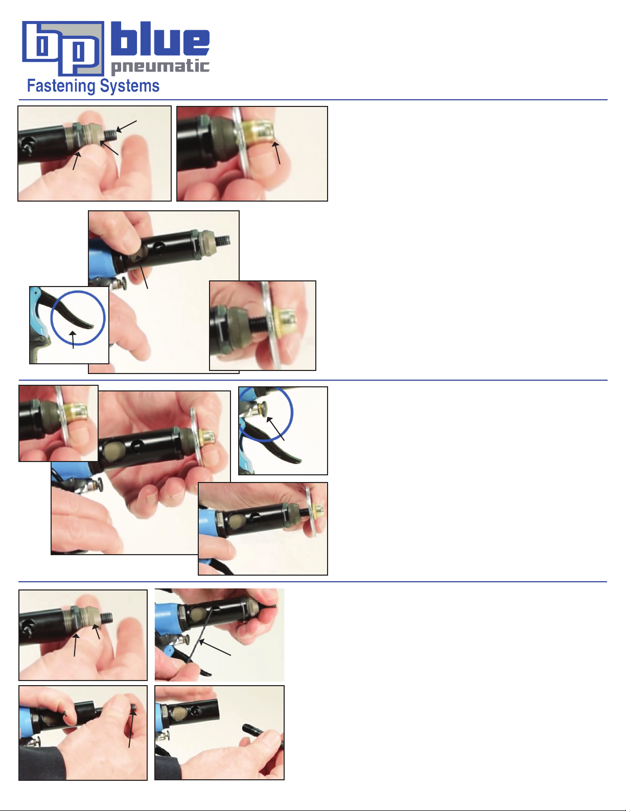
1 - Conrm Insert Compatibility and Setup
With the tool disconnected from the air source, thread
the insert onto the mandrel until it touches the anvil nut.
Make sure that the mandrel is long enough to allow one
full thread to extend past the insert. To simplify set up, be
sure measurement is based on the longest insert you will
be installing during that installation session. To make this
adjustment loosen the lock nut on the anvil nut. Thread the
anvil nut in or out to adjust the amount of exposed mandrel.
Tighten the lock nut on the anvil nut after the adjustment is
made.
2 - Adjust Stroke
Connect the tool to the air source. Make sure to operate
tool at the appropriate recommended air pressure (80-100
psi.). Pull and hold the trigger. Rotate the stroke adjustment
wheel to shorten or lengthen the stroke. The stoke is
properly adjusted when the insert is fully collapsed when
tool completes it’s pull stroke.
3 - Set the insert in your workpiece
Connect the tool to the air source. Make sure to operate tool
at the appropriate recommended air pressure (80-100 psi.).
Start threading the insert on to the mandrel. Pull the trigger
to the half pull detent and spin the mandrel in to the insert
until the insert touches the anvil nut (do not release the
trigger). g (A)
Place the insert through the hole in the workpiece. Pull the
trigger to the full pulled position and hold trigger to install
and collapse the insert in the workpiece. g (B)
Release the trigger.
Pull the release trigger to spin the mandrel out of the insert.
g (C)
(C)
4 - Easy Mandrel Change
1 - Remove the anvil nut from the nose assembly. g (A)
2 - Insert pin tool into the internal hexagon bit. g (B)
3 - Pull back on the pin tool away from the mandrel. Rotate the mandrel
Anvil Nut
Lock Nut
(A) (B)
Mandrel
(C) (D)
To see video of tool operating: http://www.bluepneumatic.com/blog/2008/06/video-demo-bp60c-spin-pull-spin-rivet-nut-tool.html
Pin Tool
and thread out of the nose assembly. g (C) (D)
4 - Thread the new mandrel into the nose assembly while still pulling
back on the hexagon bit pin tool. When the mandrel becomes slightly
snug release the pin tool (do not remove pin tool). g (D) (C)
5 - Rotate the mandrel slightly back and forth until the internal hexagon
bit sets into the end of the mandrel. A faint click will be heard and you
will feel that the mandrel is now locked in place when rotating it.
6 - Remove the pin tool and install the anvil nut and lock nut. g (B) (A)
Page 2

Limited Warranty
Blue Pneumatic brand tools are warranted to be free from defects in materials and workmanship. Tools thought to be defective
should be returned to the factory or an authorized service center or authorized distributor, where it will be examined for repair and
or replacement.
This warranty does not cover damage to tools that arise from abuse, alteration or the tool being used for anything other than its
intended use. Repair and replacement will not apply in the previously stated circumstances.
The duration of the warranty and any other warranty including, but not limited to, any implied warranty of merchantability is
expressly limited to one year beginning from the date of delivery to the original user. The obligation of Blue Pneumatic brand tool
distributors under any warranty, express or implied, is limited solely to repair or replacement from its distributor network or factory.
Page 3

Important Safeguards
READ THIS INSTRUCTION MANUAL CAREFULLY AND FULLY UNDERSTAND ALL THE INFORMATION PROVIDED PRIOR
TO USING THIS TOOL.
1 - Always inspect, maintain, and operate this tool in accordance with American National Standards Institute (ANSI) Standard
B186.1 (Safety Code for Portable Air Tools), and any other applicable codes or standards regarding the safe operation of
compressed air tools.
2 - In order to provide maximum tool life, performance, and safety, operate this tool at 85 - 110 PSI / 5.86 - 7.58 bar max. air
pressure, using dry air and a 3/8” / 9.5 mm hose. Always lubricate the tool per the manufacturer’s specications prior to operation,
or use an inline oiler with proper ltration.
3 - Always wear impact-resistant eye and / or face protection when operating
or servicing this tool. Visitor’s spectacles or home grade safety glasses are not
adequate for power tool applications.
4 - Always use hearing protection approved by OSHA or NIOSH. Lack of proper
protective gear in high-noise environments can lead to permanent loss of hearing.
5 - Always keep the tool in utmost operating condition. Lubricate and wipe down the tool after each use. Inspect for leaks, damage
to the body, or binding and/or broken moving parts.
6 - Air under pressure can cause severe injury, or possibly death, if care is not taken when using compressors, air tools, air
reservoirs, and pneumatic plumbing.
7 - Always turn off the air supply, drain water from the air line, and detach the tool from the air supply prior to removing, installing,
or adjusting any part of this tool. Inspect for frayed hose ends and damaged ttings. Replace any damaged items immediately. Do
not use quick-detach couplings at the tool – see operating instructions for correct setup. NEVER carry the tool by the hose.
8 - Slips or falls while operating air tools can result in serious injury or death.
Keep excess hose away from walkways and working areas.
9 - Air tools can vibrate during use. Vibration and repetitive motions over extended periods of time can cause injury to hands,
joints, neck, and back. Immediately stop using the tool if discomfort or pain occurs. Consult a medical professional before
resuming tool use.
10 - Always place the tool on the workpiece prior to starting the tool. Keep body stance balanced and rm while operating the tool
and do not overreach.
11 - Keep away from the rotating end of the tool. Do not wear jewelry or loose clothing. Secure long hair and beards away from
the work area. Do not wear pendant neckwear of any kind while operating rotating equipment.
12 - Tool shaft may continue to spin after the trigger is released. Avoid direct contact with tool end accessories during use. If using
gloves for cushioning or heat protection, USE EXTREME CAUTION. Gloves can bind with moving parts and result in injury or
amputation.
13 - Do not lubricate the tool with ammable uids such as kerosene, diesel, jet fuel, or aromatic spirits.
14 - Do not force the tool to operate beyond its rated capacity.
15 - Do not remove any labels, tags, or warning stickers. Replace any damaged labels prior to putting the tool in service.
 Loading...