

40 - 46 Size Almost Ready to Fly
Instructions for Final Assembly
Commemorate the Aviation's beginnings with the new Global Blue Max ARF.
A time when the nose skid was as important as the tail skid to safety minded
pilots landing on unprepared airfields, planes of this style used cutting edge
technology for their day. The Blue Max remembers those years long past. It's
open cockpit, wire spoke wheels and open framework capture a more experimental time in aviation. The high lift wing and generous wing area mean
super slow stall speed and very forgiving flight characteristics. Don't be surprised if you see beginners with this plane. Our test pilots say this plane is
easier to fly than most .40 size trainer planes. And unlike the grossly underpowered airplanes of yesteryear, the Blue Max is favorably powered using a
.40 size two stroke or a .52 size four stroke. So put on your scarf and your
goggles and get ready to go back into time. Oh, and don't forget to load that
cannon!
Version V1.0 4-99 Kit # 232500 All Contents © Copyright 1999
1

TABLE OF CONTENTS
Kit Contents...................................................3
Additional Items Required................................3
Tools and Supplies Needed..............................3
Field Support Equipment Needed......................3
Metric Conversion Chart.................................3
Wing Assembly...............................................4
Install the Dihedral Braces.........................4
Joining the Wing Halves.............................5
Wing Mounting................................................5
Install the Wing Hold Down Dowels...........5
Aligning the Wing to the Fuselage...............6
Install the Wing Struts................................6
Horizontal Stabilizer Mounting..........................6
Align the Horizontal Stabilizer.....................6
Mounting the Horizontal Stabilizer...............7
Vertical Stabilizer Mounting..............................8
Align the Vertical Stabilizer........................8
Mounting the Vertical Stabilizer..................8
Control Surface Installation..............................8
Hinge the Ailerons....................................8
Hinge the Elevator....................................9
Install the Tail Wheel Wire.........................9
Hinge the Rudder......................................9
Mounting the Tail Wheel Bracket.............10
Installing the Tail Wheel...........................10
Main Landing Gear........................................10
Aligning the Main Gear Assembly............10
Installing the Main Gear Assembly...........10
Installing the Main Gear Wheels...............11
Engine Mounting............................................11
Mounting Engine to Motor Mount.............11
Aligning the Motor Mount........................11
Mounting the Engine to Firewall...............12
Nose Skid.....................................................12
Align the Nose Skid.................................12
Installing the Nose Skid............................12
Fuel Tank......................................................13
Fuel Tank Assembly................................13
Fuel Tank Installation...............................13
Throttle Linkage............................................14
Installing the Throttle Linkage..................14
Servo Installation...........................................14
Installing the Fuselage Servo Tray............14
Installing the Aileron Servo Tray...............14
Installing the Aileron Servo......................15
Installing the Fuselage Servos..................15
Throttle Connector........................................15
Installing the Throttle Connector...............15
Rudder Pushrod............................................16
Installing the Rudder Control Horn...........16
Installing the Rudder Pushrod..................16
Elevator Pushrod..........................................17
Installing the Elevator Control Horn..........17
Installing the Elevator Pushrod.................17
Aileron Linkage............................................18
Installing the Aileron Linkage...................18
Pilot and Cannon...........................................19
Barrel Seat Assembly..............................19
Pilot and Cannon Assembly......................19
Barrel Seat Installation.............................20
Pilot Installation.......................................20
Cannon Installation..................................20
Final Assembly..............................................21
Installing the Receiver and Battery...........21
Installing the Switch................................21
Installing the Fuel Lines...........................21
Installing the Propeller.............................21
Balance........................................................21
Lateral Balance......................................22
Control Throws.............................................22
Flight Preparation..........................................22
Preflight Check.......................................23
Basics of Flight.............................................23
Product Evaluation........................................26
Global guarantees this kit to be free from defects in both material and workmanship, at the date of purchase. This does
not cover any components parts damaged by use, misuse or modification. In no case shall Global's liability exceed the
original cost of the purchased kit.
In that Global has no control over the final assembly or material used for final assembly , no liability shall be assumed for
any damage resulting from the use by the user of the final user-assembled product. By the act of using the final userassembled product, the user accepts all resulting liability.
T o make your modeling experience totally enjoyable, we recommend that you get experienced, knowledgable help
with assembly and during your first flights. Your local hobby shop has information about flying clubs in your area
whose membership includes qualified instructors. You can also contact the AMA at the address below.
Academy of Model Aeronautics
5151 East Memorial Drive
Muncie, IN. 47302-9252
(800) 435-9262
www.modelaircraft.or g
2

This instruction manual is designed to help you build a straight, great flying airplane. Please read this
manual thoroughly before beginning assembly of your new Blue Max. Use the parts listing below to
identify and separate all parts before beginning assembly .
** KIT CONTENTS** W e have organized the parts as they come out of the box for better identification
during assembly . W e recommend you regroup the parts in the same manner. This will ensure you have all
of the parts required before you begin assembly and will also help you familiarize yourself with each part.
KIT CONTENTS
AIRFRAME ASSEMBLIES
o {2} Wing Halves w/Ailerons and Hinges
o {1} Fuselage
o {1 } Horizontal Stabilizer w/Elevator and Hinges
o { 1} Vertical Stabilizer w/Rudder and Hinges
o {2} Wing Struts
MAIN GEAR ASSEMBL Y
o {1 } W ire Main Gear Assembly
o { 1 } Wire Nose Skid
o { 2 } Nylon Mounting Straps w/4mm Slot
o { 5 } Nylon Mounting Straps w/3mm Slot
o { 2} 127mm Diameter W ire Spoke Wheels
o {2 } Nylon Axle Spacers
o { 2} Wheel Collars w/3mm x 6mm Machine Screws
o {14} 3mm x 12mm W ood Screws
TAIL WHEEL ASSEMBL Y
o {1 } T ail Wheel W ire w/ Mounting Bracket
o { 1} 25mm Diameter T ail Wheel
o {2 } Wheel Collars w/3mm x 6mm Machine Screws
o {3 } 3mm x 12mm Wood Screws
ELEV A T OR CONTROL SYSTEM
o {1 } 990mm Nylon Pushrod
o {1 } 1.5mm x 50mm Threaded Wire w/Z-Bend
o {1 } 1.5mm x 45mm Wire Threaded Each End
o {1 } Nylon Clevis w/1.5mm I.D. Hole
o {1 } Nylon Control Horn
o { 1 } Nylon Control Horn Backplate
o {2 } 2mm x 15mm Machine Screws
RUDDER CONTROL SYSTEM
o {1 } 990mm Nylon Pushrod
o {1 } 1.5mm x 50mm Threaded Wire w/Z-Bend
o {1 } 1.5mm x 45mm Wire Threaded Both Ends
o {1 } Nylon Clevise w/1.5mm I.D. Hole
o {1 } Nylon Control Horn
o { 1 } Nylon Control Horn Backplate
o {2 } 2mm x 15mm Machine Screws
THROTTLE CONTROL SYSTEM
o {1} 2mm x 300mm Pushrod W ire
o {1} Adjustable Servo Connector Assembly
AILERON CONTROL SYSTEM
o {2 } Nylon Clevises w/2mm I.D. Hole
o {2 } 2mm x 150mm Threaded Rod
o {2} Nylon Snap Keepers
o {2} Nylon Adjustable Control Horns
MOTOR MOUNT ASSEMBLY
o {2} Nylon Motor Mount Beams
o {4 } 3mm x 25mm Machine Screws
o {4} 3mm x 20mm Machine Screws
o {4 } 3mm Nylon Insert Nuts
o { 4} 3mm Blind Nuts
o {12} 3mm Flat W ashers
MISCELLANEOUS ITEMS
o { 1} Aileron Servo Tray (W-39)
o { 1} Forward Dihedral Brace (W-40)
o {1 } Rear Dihedral Brace (W-41)
o {2 } W ing Hold Down Dowels (W-43)
o { 1} Fuselage Servo Tray (D-47)
o {6 } 3mm x 10mm Machine Screws
o {6 } 3mm Flat W ashers
o {4 } 3mm x 12mm W ood Screws
FUEL T ANK
o {1 } Molded Fuel Tank
o { 1 } 20mm Front Squash Plate
o { 1} 18mm Rear Squash Plate
o { 1} Rubber Stopper
o {1 } 70mm Length of Fuel Tubing
o { 1 } Metal W eighted Pick-Up
o { 3 ) Aluminum Tubes
o {1 } 3mm x 20mm Machine Screw
PILOT AND CANNON ASSEMBL Y
o {1} Prepainted Balsa Cannon Mount
o {2} Plastic Body Halves
o {2} Plastic Cannon Halves
o {2 } Plastic Head Halves
o { 1} Balsa Barrel Seat Platform
o {1 } Plastic Barrel Seat
o { 1} Plastic Barrel Seat Back
3

ADDITIONAL ITEMS REQUIRED
o {1}Hitec 4 or More Channel Radio w/4 Servos
o {1}Dubro Foam Rubber # 513
o {1}Global Fuel Line # 115923
o {1}Arco # 64 Rubber Bands # 24649
FOR 2-STROKE ENGINE
o {1}Magnum XL .40-.46 T wo Stroke
o {1}Magnum 1/4” Spinner Nut # 237310
o {1}Propeller T o Suit Engine
o {1}Thunderbolt Glow Plug # 115493
TOOLS AND SUPPLIES NEEDED
o Kwik Bond Thin C/A # 887500
o Kwik Bond Thick C/A # 887510
o Kwik Bond 5 Minute Epoxy # 887560
o Kwik Bond 30 Minute Epoxy # 887565
o Wilhold Silicon Sealer # 00684
o Electric Drill
o Assorted Drill Bits
o Modeling Knife
o Wire Cutters
o Machine Oil or V aseline
FOR 4-STROKE ENGINE
o {1}Magnum XL .52RFS Four Stroke
o {1}Magnum 1/4” Spinner Nut # 237310
o {1}Propeller T o Suit Engine
o {1}Thunderbolt Glow Plug # 115490
o Straight Edge Ruler
o Dremel Tool w/Assorted Bits
o Phillips Screwdriver
o Z-Bend Pliers
o 3mm Hex Wrench
o Builders Triangle
o 220 Grit Sandpaper
o Masking T ape
o Paper T owels
o Rubbing Alcohol
TO FINISH PILOT AND CANNON
o T estors Contour Putty # 3511X
o 320 Grit Sandpaper
o Find & Medium Paint Brushes
o 3M Fine Line Masking Tape # 218-06300
o Coverite Flat Clear Paint # COVR1280
o Paint Thinner
o Tan, White, Brown and Orange - Mix to
make skin color and lip color
FIELD SUPPORT EQUIPMENT NEEDED
o Magnum 12V Electric Starter (# 361006)
o Magnum 12V Fuel Pump (# 237377)
o Magnum Locking Glow Clip (# 237440)
o Global 12V Battery (# 110171 )
METRIC CONVERSION CHART
T o convert inches into millimeters: Inches x 25.4 = MM
1/64” = .4mm
1/32” = .8mm
1/16” = 1.6mm
3/32” = 2.4mm
1/8” = 3.2mm
5/32” = 4.0mm
3/16” = 4.8mm
1/4” = 6.4mm
3/8” = 9.5mm
1/2” = 12.7mm
5/8” = 15.9mm
3/4” = 19.0mm
o Flat Black - Eyebrows, Mustache, Hair
and Cannon
o White and Blue - Eyes
o Light Blue - Body
o Gold - Simulate Buttons and Straps of Jacket
o Brass - Cannon Trim
o Brown - Cannon Barrel Seat
o Global 12V Charger (# 110270 )
o Magnum Power Panel (# 237390)
o Global Field Buddy Flight Box (# 233072)
o Magnum 4-Way Wrench (# 237420)
1 ” = 25.4mm
2 ” = 50.8mm
3 ” = 76.2mm
6 ” = 152.4mm
12 ” = 304.8mm
18 ” = 457.2mm
21 ” = 533.4mm
24 ” = 609.6mm
30 ” = 762.0mm
36 ” = 914.4mm
4
If you should find a part missing or have questions about assembly , please call or write to the address below:
Customer Service Center
18480 Bandilier Circle
Fountain V alley , CA. 92728
Phone: (714) 963-0329
Fax: (714) 964-6236
E-Mail: globalhobby@earthlink.net
**SUGGESTION** To avoid scratching your new airplane, do not unwrap the pieces until they are
needed for assembly . Cover your workbench with an old towel or brown paper , both to protect the aircraft
and to protect the table. Keep a couple of jars or bowls handy to hold the small parts after you open the
bags.
**NOTE** Please trial fit all the parts. Make sure you have the correct parts and that they fit and are
aligned properly before gluing! This will assure proper assembly . Since the Blue Max is hand made from
natural materials, every plane is unique and minor adjustments may have to be made. However, you
should find the fit superior and assembly simple.
WING ASSEMBLY
PARTS REQUIRED
o {2} Wing Halves w/Ailerons and Hinges
o {1 } Forward Dihedral Brace (W-40)
o {1 } Rear Dihedral Brace (W-41)
INST ALL THE DIHEDRAL BRACES
o 1) Look at the face of each root rib on both
wing halves. Notice how the excess covering material overlaps onto them. Using a modeling knife,
carefully cut away the covering from both of the
root ribs. Leave about 1/16” of covering overlapping so it does not pull away .
It is important that the covering be removed
from the root ribs. This will ensure an adequate wood-to-wood glue joint and prevent
wing failure during flight.
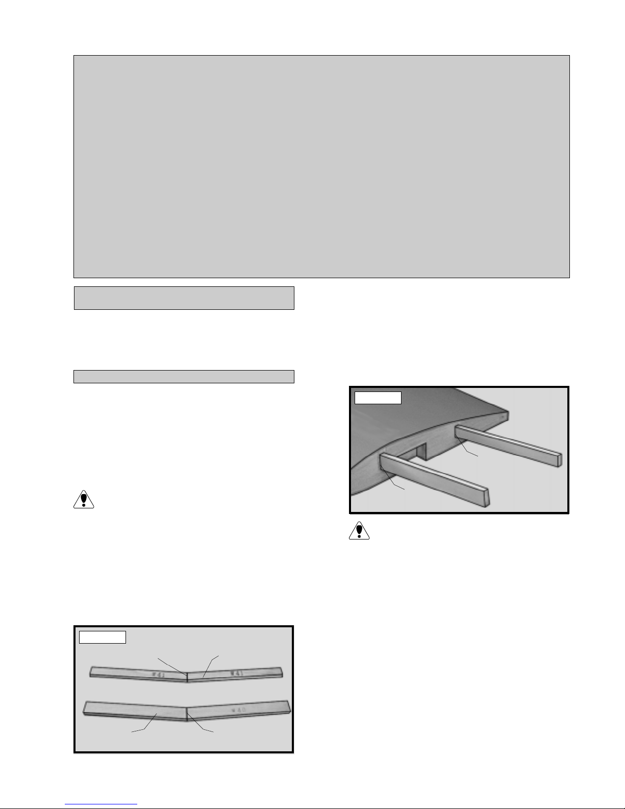
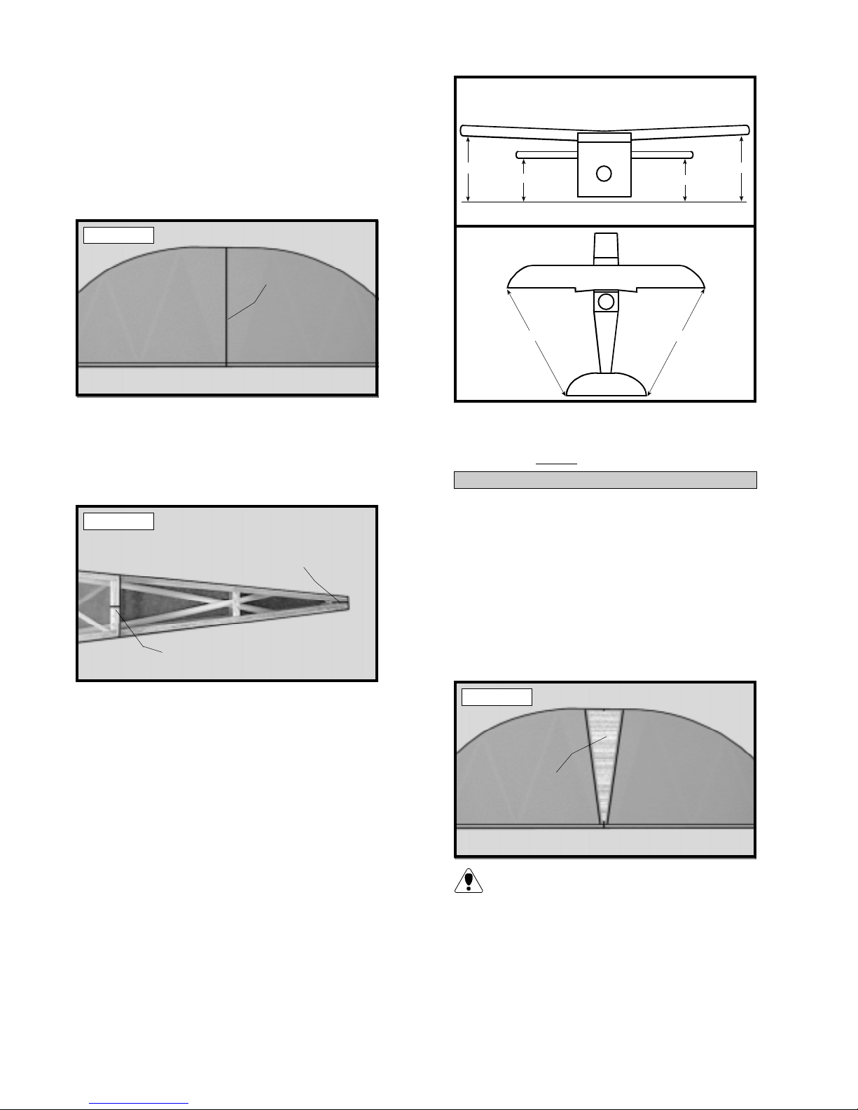
o 2) Using a ruler and a pen, locate and mark
the center section of the forward and rear dihedral braces (W-40 and W-41). Draw a vertical
line at this location on both braces. See photo
# 1 below .
Photo # 1
DRAW CENTERLINE
REAR
DIHEDRAL
BRACE
o 3) T est fit the dihedral braces into their respective boxes in each wing half. W-40 fits into
the forward box and W-41 fits into the rear box.
The braces should slide into each wing half up to
the centerlines. If they do not, remove them and
lightly sand the edges and tip of each one until the
proper fit is obtained. See photo # 2 below .
Photo # 2
SLIDE IN UP
TO CENTERLINE
SLIDE IN UP
TO CENTERLINE
The dihedral braces are cut in the shape of
a "V". They should be installed with the "V"
shape facing upright to form the proper dihedral
angle when the wings are joined.
o 4) T est fit both of the wing halves together
with the dihedral braces temporarily installed. Do
not glue them in at this time! The wing halves
should fit together tightly with little or no gaps in the
center section joint. If the center section joint is
not tight, remove the wing halves and lightly sand
the edges and tips of each brace. Reinstall the
wing halves and braces and test the fit until you are
satisfied that the center section joint is tight.
FORW ARD
DIHEDRAL
BRACE
DRAW CENTERLINE
o 5) When satisfied with the fit of the wing
halves, remove the dihedral braces.
5
JOINING THE WING HAL VES
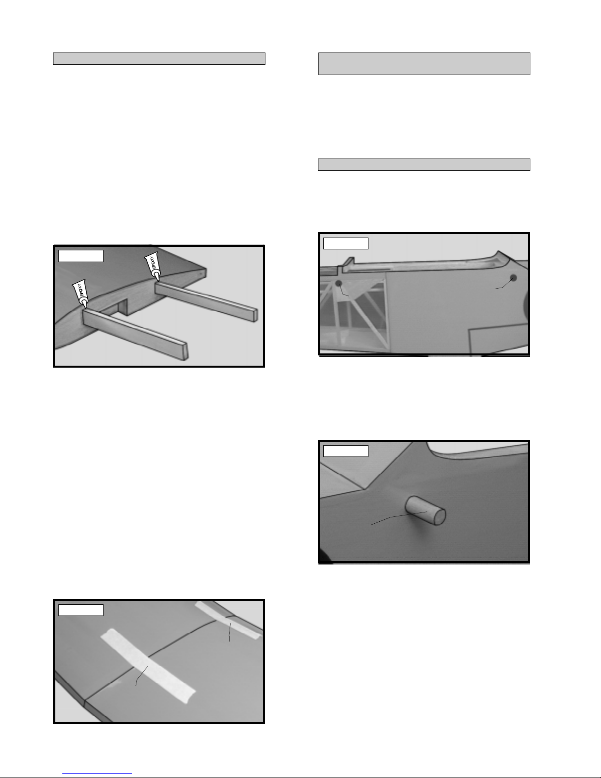
o 6) Mix a generous amount of Kwik Bond
30 Minute Epoxy . W orking with only one wing
half for now , apply a thin layer of epoxy inside
both dihedral brace boxes and on only half of
each dihedral brace. Make sure to cover the top
and bottom as well as the sides and use enough
epoxy to fill any gaps.
WING MOUNTING
PARTS REQUIRED
o {1 } Fuselage
o { 2 } Wing Hold Down Dowels (W-43)
o {2} Wing Struts
o {6 } 3mm x 10mm Machine Screws
o {6 } 3mm Flat Washers
INSTALL THE WING HOLD DOWN DOWELS
o 7) Slide the dihedral braces into the boxes
up to the centerlines. Remove any excess epoxy
before it dries using a paper towel and rubbing
alcohol. Allow the epoxy to cure before proceeding. See photo # 3 below.
Photo # 3
o 8) Once the epoxy has cured, trial fit both
wing halves together to double check that the wing
halves still fit correctly .
o 9) Mix a generous amount of Kwik Bond 30
Minute Epoxy . Apply a thin layer of epoxy to the
exposed halves of both dihedral braces, the inside
of both dihedral brace boxes i n the second wing
half and the entire surface of both root ribs. Make
sure to use enough epoxy to fill any gaps.
o 1) Using a modeling knife, carefully remove
the covering from over the four predrilled holes in
the fuselage sides. T wo holes are located on each
side of the fuselage. See photo # 5 below .
Photo # 5
REMOVE COVERING
REMOVE COVERING
(both sides)
(both sides)
o 2) Slide one wing hold down dowel through
the two forward holes in the fuselage sides and
the second dowel through the two rear holes in
the fuselage sides. Adjust the dowels so both
ends of each dowel protrude from the fuselage
sides an equal amount. See photo # 6 below.
Photo # 6
o 10) Slide the two wing halves together and
carefully align them at the leading and trailing edges.
Wipe away any excess epoxy using a paper towel
and rubbing alcohol. Use masking tape to hold the
wing halves in place until the epoxy cures. See
photo # 4 below .
Photo # 4
MASKING
TAPE
MASKING
TAPE
WING HOLD
DOWN DOWEL
o 3) When satisfied with the fit, use a pen and
place a mark on each dowel at the point where
they exit the fuselage sides.
o 4) Remove the dowels and mix a small
amount of Kwik Bond 30 Minute Epoxy . Apply
a thin layer of epoxy to the inside edges of all four
holes in the fuselage. Carefully slide the dowels
into place up to the marks made. Double check
that they are centered and use paper towels and
rubbing alcohol to remove any excess epoxy before it cures.
6
ALIGNING THE WING TO THE FUSELAGE
o 5) Using a ruler and a pen, locate and mark
the centerline of the fuselage at both the front and
rear of the wing saddle. Place a mark at both
locations. See photo # 7 below .
Photo # 7
MARK
CENTERLINE
MARK
CENTERLINE
Photo # 9
REMOVE COVERING
WING TIP
AILERON
o 8) Place the wing into the wing saddle. Align
the centerline of the wing at both the leading and
trailing edges with the two marks you made on
the fuselage.
These two marks will help you align the wing
when you install it on the fuselage. Y ou may
wish to make these marks in permanent ink so
you can align the wing correctly each time you
install the wing. This will ensure the wing is aligned
properly each time you fly the airplane.
INST ALL THE WING STRUTS
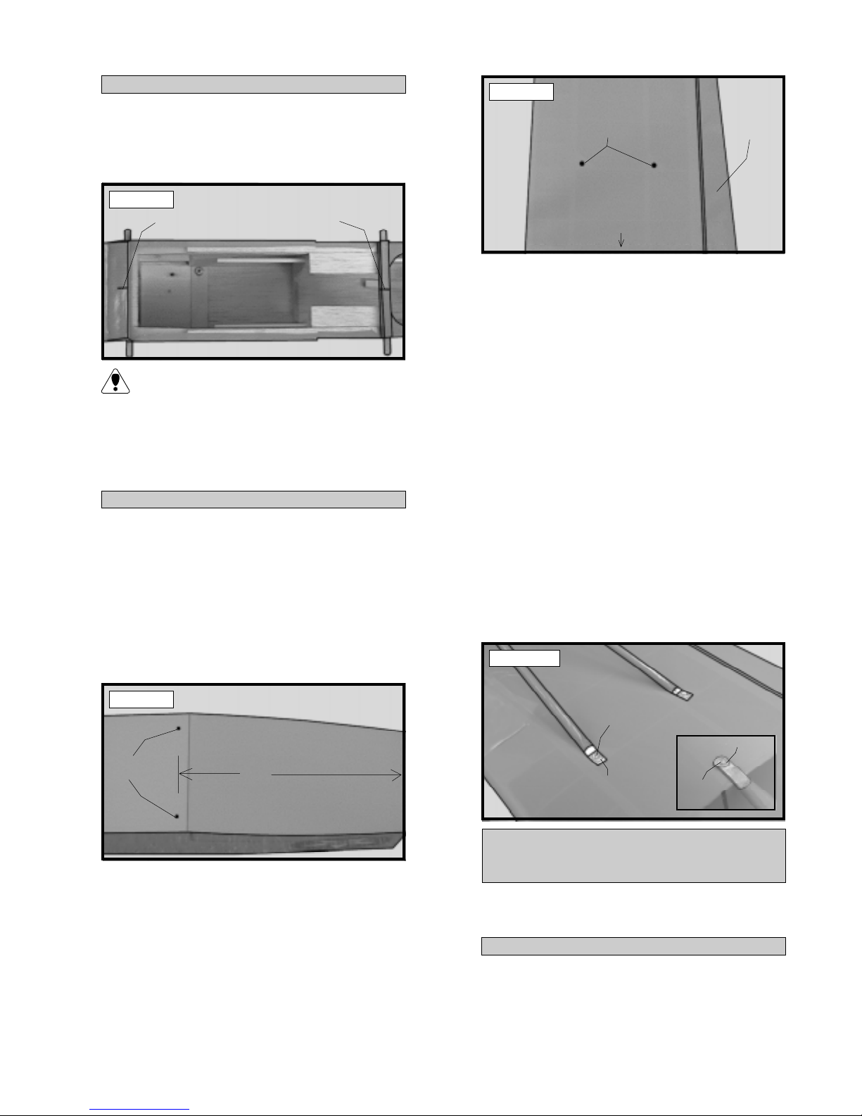
o 6) There are two preinstalled blind nuts that
are used to mount the wing struts to the bottom
of the fuselage. Using a modeling knife, carefully remove the covering from over the two blind
nut holes on the bottom of the fuselage. The
holes are located 1/2” in from the fuselage sides
and 8-1/4” back from the front of the firewall.
See photo # 8 below .
Photo # 8
REMOVE
COVERING
8-1/4”
o 9) Using a couple of # 64 rubber bands,
temporarily secure the wing in place making sure
it is aligned. T o correctly install the rubber bands,
hook one over one of the front wing hold down
dowels, carefully pull it back over the top of the
wing and hook it over the rear hold down dowel
on the same side. Install two rubber bands on
each side for now .
o 10) Bolt the wing struts to the wing and to
the fuselage using the six 3mm x 6mm machine
screws and six 3mm flat washers. It may be
necessary to move the wing slightly to properly
align the holes in the struts with the blind nuts.
See photo # 10 below .
Photo # 10
3mm x
6mm
SCREW
3mm FLAT
WASHER
3mm FLATWASHER
3mm x 6mm
SCREW
o 7) There are also two blind nuts preinstalled in
each wing half. They are located in plywood gussets, 20” out from the centerline of the wing. The
rear blind nut is 2-3/4” forward of the trailing edge
and the front blind nut is 3” back from the leading
edge. Using a modeling knife, carefully remove the
covering from over the two blind nut holes in each
wing half. See photo # 9 at top right.
HORIZONTAL STABILIZER
MOUNTING
PARTS REQUIRED
o {1} Horizontal Stabilizer w/Elevator and Hinges
ALIGN THE HORIZONT AL STABILIZER
o 1) Remove the elevator from the horizontal
stabilizer and set it aside for now . Turn the stabilizer upside down on your work surface. The bottom side is the flat side and should be facing up.
7
o 2) Using a ruler and a pen, locate and mark
the centerline of the horizontal stabilizer at the
trailing edge and place a mark. Use a triangle
and extend this mark, from back to front, across
the bottom of the stabilizer. Also place centerline marks on the top of the stabilizer at the leading
and trailing edges only. See photo # 11 below .
Figure # 1
B
A
A1
B1
Photo # 1 1
DRA W
CENTERLINE
o 3) Using a ruler and a pen, locate and place
a mark at the centerline of the fuselage at the front
and rear of the stabilizer mounting platform. These
marks will be used to line up the stabilizer with
the fuselage. See photo # 12 below .
Photo # 12
DRA W
CENTERLINE
DRAW
CENTERLINE
Figure # 2
C
C1
o 5) When you are satisfied with the alignment,
hold the stabilizer in place with T- pins or masking tape, but do not glue at this time.
MOUNTING THE HORIZONT AL STABILIZER
o 6) With the stabilizer held firmly in place, use
a pen and draw a line on the stabilizer where it
and the fuselage sides meet. Do this on both the
right and le ft sides on the bottom of the stabilizer.
o 7) Remove the stabilizer. Using the lines you
just drew as a guide, carefully remove the covering
from between them, using a modeling knife. See
photo # 13 below.
o 4) Attach the wing to the fuselage and remove both ailerons. Set the horizontal stabilizer
onto the stabilizer mounting platform on the fuselage. Align the centerline marks on top of the
stabilizer with the centerline marks at the front
and rear of the stabilizer mounting platform. When
the marks are aligned hold the stabilizer in position using a couple of T-pins. Align the horizontal
stabilizer with the wing. When viewed from the
rear, the horizontal stabilizer should be level with
the wing. If it is not level, use sandpaper and
sand down the high side of the stabilizer mounting platform until the proper alignment is achieved.
The tips of the stabilizer should also be equal distance from the tips of the wing. See figures # 1
and # 2 at top right.
Photo # 13
REMOVE
COVERING
When cutting through the covering to re-
move it, cut with only enough pressure to
only cut through the covering itself. Cutting into
the balsa structure may weaken it and cause possible failure in flight.
8
o 8) When you are satisfied that everything is
aligned correctly , mix up a generous amount of
Kwik Bond 30 Minute Epoxy . Apply a thin layer
to the bottom of the stabilizer mounting area and
to the top of the stabilizer mounting platform on
the fuselage. Set the stabilizer in place and realign. Double check all of your measurements
once more before the epoxy cures. Hold the stabilizer in place with T-pins or masking tape and
remove any excess epoxy using paper towels and
rubbing alcohol.
o 4) Set the vertical stabilizer back in place.
Using a triangle, check to ensure that the vertical
stabilizer is aligned 90º to the horizontal stabilizer .
See figure # 3 below .
Figure # 3
90º
VERTICAL STABILIZER
MOUNTING
PARTS REQUIRED
o {1} V ertical Stabilizer w/Rudder and Hinges
ALIGN THE VERTICAL ST ABILIZER
o 1) Remove the rudder from the stabilizer .
Slide the stabilizer into the slot in the top of the
horizontal stabilizer . The rear edge of the vertical
stabilizer should be even with the rear edge of the
horizontal stabilizer and fuselage. It should also
be pushed down completely into the slot.
o 2) Using a pen, draw a line on each side of
the vertical stabilizer where it meets the top of the
slot on the horizontal stabilizer.
o 3) Remove the stabilizer. Using a modeling
knife, remove the covering from just below the lines
you drew . Also remove the covering from the bottom edge of the stabilizer. See photo # 14 below .
Photo # 14
MOUNTING THE VERTICAL ST ABILIZER
o 5) When you are satisfied that everything is
aligned correctly , mix up a generous amount of
Kwik Bond 30 Minute Epoxy . Apply a thin layer
to the mounting slot in the top horizontal stabilizer
and to the sides and bottom of the vertical stabilizer mounting area. Set the stabilizer in place
and realign. Double check all of your measurements once more before the epoxy cures. Hold
the stabilizer in place with T-pins or masking tape
and remove any excess epoxy using paper towels and rubbing alcohol. Allow the epoxy to fully
cure before proceeding.
CONTROL SURFACE
INSTALLATION
PARTS REQUIRED
o {2} Ailerons w/Hinges
o { 1 } Elevator w/Hinges
o { 1 } Rudder w/Hinges
o { 1 } Tail Wheel W ire w/Mounting Bracket
o { 1} 25mm Diameter Tail Wheel
o {2 } Wheel Collars w/3mm x 6mm Machine Screws
o {3 } 3mm x 12mm W ood Screws
REMOVE
COVERING
When cutting through the covering to re-
move it, cut with only enough pressure to
only cut through the covering itself. Cutting into
the balsa structure may weaken it. There may
also be covering material overlapped on the inside edges of the vertical stabilizer mounting slot
in the horizontal stabilizer . Using a modeling knife,
carefully remove this covering also. This will help
insure a good glue joint.
HINGE THE AILERONS
o 1) The C/A hinges have already been glued
into the two ailerons. W orking with one aileron
at a time, slide the aileron and it's hinges into their
precut hinge slots in the trailing edge of the wing,
making sure the torque rod is firmly seated in the
precut hole in the leading edge of the aileron. Slide
the aileron in until it is tight against the trailing
edge of the wing. The maximum hinge gap should
be no more than 1/32” and the tip of the aileron
should be flush with the tip of the wing.
9

o 2) When satisfied with the fit, remove the aileron and slide a small piece of waxed paper between the aileron torque rod and the trailing edge
of the wing. See photo # 15 below.
Photo # 15
TORQUE ROD
WAXED PAPER
The waxed paper will prevent epoxy from
gluing the torque rod to the trailing edge of
the wing.
o 3) Mix up a small amount of Kwik Bond 30
Minute Epoxy . Apply a thin layer of epoxy to the
aileron torque rod. Also use a toothpick and pack
epoxy into the predrilled hole in the aileron.
o 7) With the elevator tight against the stabilizer, rotate the elevator down about 45º. Apply
six drops of Kwik Bond Thin C/A to the exposed
area of each hinge. Allow the glue to cure for
about ten minutes. Once cured, the elevator may
be stiff and difficult to move. This is normal.
Gently move the elevator up and down about five
to ten times to free it up.
INST ALL THE TAIL WHEEL WIRE
o 8) Using a ruler and a pen, measure up 3/4”
from the bottom of the rudder, at the leading edge,
and place a mark.
o 9) Using a 3/32” drill bit, drill a hole into the
rudder at the mark made. Using a modeling knife,
cut a groove from the hole, down to the bottom of
the rudder . Make the hole deep enough for the tail
wheel wire to set flush in. See figure # 4 below .
Figure # 4
o 4) Slide the aileron and it's hinges into their
precut hinge slots in the trailing edge of the wing,
making sure the torque rod is firmly seated in the
precut hole in the leading edge of the aileron. With
the aileron tight against the wing, rotate the aileron down about 45º. Apply six drops of Kwik
Bond Thin C/A to the exposed area of each hinge.
Allow the glue to cure for about ten minutes.
Once cured, the aileron may be stiff and difficult
to move. This is normal. Gently move the aileron
up and down about five to ten times to free it up.
o 5) Repeat steps # 1 - # 4 for the second
aileron.
HINGE THE ELEV ATOR
o 6) The C/A hinges have already been glued
into the elevator . Slide the elevator and it's hinges
into their precut hinge slots in the trailing edge of
the horizontal stabilizer. Slide the elevator in until
it is tight against the trailing edge of the stabilizer . The maximum hinge gap should be no more
than 1/32”. See photo # 16 below .
DRILL
HOLE
CUT
GROOVE
o 10) Mix up a small amount of Kwik Bond 5
Minute Epoxy . Apply the epoxy to only those
parts of the tail wheel wire that will be glued to
the rudder. Pack epoxy into the hole you drilled
in the leading edge of the rudder also.
o 11) Insert the tail wheel wire into the rudder .
Clean up any excess epoxy using a paper towel and
rubbing alcohol. See photo # 17 below.
Photo # 17
TAIL WHEEL
WIRE
Photo # 16
1/32”
ELEVATOR
STABILIZER
HINGE THE RUDDER
o 12) The C/A hinges have already been
glued into the rudder . Slide the rudder and it's
hinges into their precut hinge slots in the trailing
edge of the vertical stabilizer . Slide the rudder
in until it is tight against the trailing edge of the
stabilizer. The maximum hinge gap should be no
more than 1/32”.
10

o 13) W ith the rudder tight against the stabilizer, rotate the rudder to one side about 45º. Apply six drops of Kwik Bond Thin C/A to the exposed area of each hinge. Allow the glue to cure
for about ten minutes. Once cured, the rudder
may be stiff and difficult to move. This is normal.
Gently move the rudder back and forth about five
to ten times to free it up.
MOUNTING THE TAIL WHEEL BRACKET
o 14) Align the tail wheel mounting bracket
with the centerline of the fuselage. Use a pen
and mark the three mounting locations on the
fuselage.
o 15) Move the mounting bracket to the side.
Using a 1/16” drill bit, drill three pilot holes through
the bottom of the fuselage at the marks you just
made.
o 16) Secure the mounting bracket in place using three 3mm x 12mm wood screws. See photo
# 18 below .
Photo # 18
3mm x 10mm
WOOD SCREWS
WHEEL
COLLAR
TAIL WHEEL
MAIN LANDING GEAR
PARTS REQUIRED
o {1} Wire Main Gear Assembly
o { 2 } Nylon Mounting Straps w/4mm Slot
o { 2 } Nylon Mounting Straps w/3mm Slot
o { 2 } Nylon Axle Spacers
o { 2} Wheel Collars w/3mm x 6mm Machine Screws
o {8 } 3mm x 12mm Wood Screws
o {2 } 127mm Diameter Wire Spoke Wheels
ALIGNING THE MAIN GEAR ASSEMBL Y
o 1) Inspect each of the nylon mounting straps.
Some straps have 4mm molded slots and others
have 3mm molded slots. T o attach the main gear
assembly you will need two straps with 4mm
molded slots and two straps with 3mm molded
slots.
o 2) Set the main gear assembly in place on
the bottom of the fuselage. The larger diameter
wire (4mm) should face to the rear and the front
edge of the forward gear wire should be 4” back
from the firewall. See photo # 19 below.
Photo # 19
GEAR
WIRE
FRONT
MOUNTING
BRACKET
INSTALLING THE T AIL WHEEL
o 17 ) Slide the wheel collar that has been
preinstalled onto the tail wheel wire tight up
against the bottom of the bracket. Tighten the
3mm x 6mm machine screw to hold it in place.
o 18) Install the 25mm diameter tail wheel onto
the tail wheel wire. Secure the tail wheel in place
using one wheel collar and one 3mm x 6mm machine screw . Slide the wheel collar on enough so
it is up against the tail wheel, but not so tight that
the tail wheel won't turn. The tail wheel should
rotate without binding.
o 3) While holding the gear assembly in this
position, center it side-to-side on the fuselage.
When satisfied with the alignment use a couple of
pieces of masking tape to hold the gear in position.
INST ALLING THE MAIN GEAR ASSEMBLY
o 4) With the gear held firmly in position, place
two 3mm nylon mounting straps, equal distance
apart, over the front wire. Place two 4mm nylon
mounting straps, equal distance apart, over the
rear wire.
o 5) Using a 1/16” drill bit, drill pilot holes
through the fuselage for the mounting screws. Use
the nylon straps as a guide for correct placement
of the holes.
11

o 6) Secure the gear assembly in place by installing the eight 3mm x 12mm wood screws
through the mounting straps and remove the
masking tape. See photo # 20 below.
Photo # 20
3mm x10mm
WOOD SCREWS
INST ALLING THE MAIN GEAR WHEELS
MOUNTING
STRAPS
o 7) Slide one nylon spacer onto each axle.
Slide one 127mm diameter wire spoke wheel onto
each axle and up against the nylon spacers. Secure the wheels in place by sliding one wheel collar onto each axle and up against the wheels.
Tighten the 3mm x 6mm machine screw in the
wheel collars. The wheels should be able to rotate without binding.
o 3) When satisfied with the alignment of the
engine, remove the beams from the clamp and
drill 1/8” holes through the mounting beams at
the four engine mounting hole locations.
o 4) Mount the engine to the mounting beams
using the four 3mm x 25mm machine screws, eight
3mm flat washers and four 3mm lock nuts. Tighten
the screws and nuts completely .
If using an engine equipped with a remote
needle valve we recommend mounting the
needle valve to the engine prior to installing the
engine on the motor mount beams.
ALIGNING THE MOTOR MOUNT
o 5) The engine is mounted upright on the firewall. Using a ruler and a pen, measure and draw
a vertical centerline and a horizontal centerline on
the firewall. See photo # 22 below .
Photo # 22
ENGINE MOUNTING
PARTS REQUIRED
o {2} Nylon Motor Mount Beams
o {4 } 3mm x 20mm Machine Screws
o {4} 3mm x 25mm Machine Screws
o {12}3mm Flat Washers
o {4 } 3mm Lock Nuts
o {4 } 3mm Blind Nuts
MOUNTING ENGINE TO MOTOR MOUNT
o 1) Using a clamp or a vise, align the two motor
mount beams and clamp them together. The beam
halves are universal and the webbing should face
the outside edges. See photo # 21 below.
Photo # 21
ALIGN
EDGES
ALIGN
EDGES
o 6) Using a ruler and a pen, measure 1/8” to
the right of the vertical centerline (looking at the
firewall) and draw a second vertical line. Measure
1/2” up from the horizontal centerline and draw a
second horizontal line. Measure 7/8” down from
the horizontal centerline and draw a third horizontal line. See photo # 23 below .
Photo # 23
1/2”
7/8”
o 2) Mark the locations of the four engine
mounting holes on the beams using a pencil. For
the engine to align properly , it is important that
the front edge of the engine's drive washer be
3-3/4” forward from the rear edge of the mounting beams.
12

o 7) With your engine still installed on the motor mount beams, use a ruler and measure the width
between the predrilled mounting holes in the motor
mount beams. This distance will vary depending
on the brand and size of the engine you have chosen. See photo # 24 below.
Photo # 24
Photo # 26
NOSE SKID
D = DISTANCE
BETWEEN
MOTOR
MOUNT
BEAMS
D
o 8) Divide the measurement found in step
# 7 in half. Measure this resulting distance and
draw one vertical line to the right and one to
the left of the second vertical line. See photo
# 25 below .
Photo # 25
o 9) Hold the motor mount assembly up to the
firewall and double check that the four intersecting lines line up with the four predrilled holes in
the motor mount beams.
The motor mount assembly is offset to the
airplane's left side (looking from the rear) to
compensate for the 2º of right thrust built into the
firewall. Offsetting the engine will allow the crankshaft to align with the centerline of the fuselage.
MOUNTING THE ENGINE TO FIREW ALL
o 10) Using a 1/8” drill bit, drill the four mounting holes through the firewall for the motor mount.
o 11) Mount the motor mount assembly to the
firewall using the four 3mm x 20mm machine
screws, four 3mm flat washers and four 3mm blind
nuts. Tighten the screws completely until the blind
nuts have been completely seated in the back of
the firewall. See photo # 26 at top right.
PARTS REQUIRED
o {1} Wire Nose Skid
o { 3 } Nylon Mounting Straps w/3mm Slot
o { 6} 3mm x 12mm Wood Screws
ALIGN THE NOSE SKID
o 1) Set the nose skid onto the front of the firewall. The vertical wire of the skid should be 1/8”
to the left of the centerline of the firewall (looking
at the firewall). T o achieve the correct height, the
lower edge of the horizontal wire should be 3/8”
up from the bottom of the fuselage.
o 2) When satisfied with the alignment use a
couple of pieces of masking tape to hold the skid
in position. See photo # 27 below.
Photo # 27
3/8”
ENGINE MOUNT
NOSE
SKID
INST ALLING THE NOSE SKID
REMOVED FOR
CLARITY. FUSELAGE
SHOWN UPSIDE DOWN.
o 3) With the nose skid held firmly in position,
place one nylon mounting strap over the horizontal wire and one over the shorter vertical wire,
next to the motor mount. Place the third nylon
strap over the rear section of the nose skid, on
the fuselage bottom.
o 4) Using a 1/16” drill bit, drill pilot holes
through the firewall and fuselage bottom for the
six mounting screws. Use the nylon straps as a
guide for correct placement of the holes.
13

o 5) Secure the nose skid in place by installing the six 3mm x 12mm wood screws through
the mounting straps and remove the masking tape.
See photo # 28 below.
Photo # 28
3mm x 10mm
WOOD SCREWS
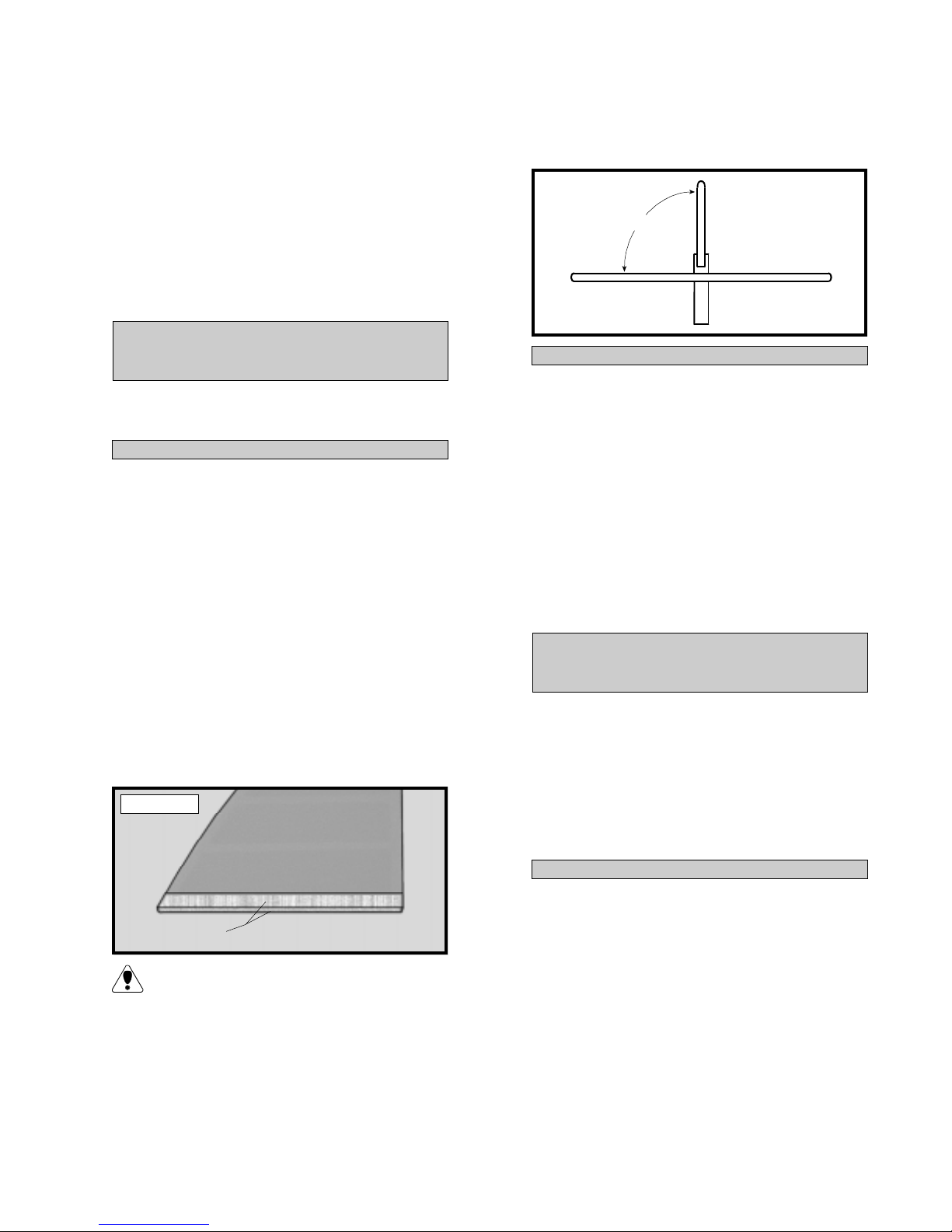
o 4) Carefully bend the longer of the two tubes
up at a 45º angle. This tube is the vent tube.
When the stopper assembly is installed in the tank,
the top of the vent tube should rest just below the
top of the tank.
MOUNTING
STRAPS
FUEL TANK
PARTS REQUIRED
o {1} Molded Fuel T ank
o {1} Rubber Stopper
o {1 } 20mm Diameter Front Squash Plate
o {1 } 18mm Diameter Rear Squash Plate
o {1 } 3mm x 20mm Machine Screw
o {1 } Weighted Metal Pick-Up
o { 3 } Aluminum Tubes
o { 1} 70mm Silicon Fuel Tube
FUEL T ANK ASSEMBLY
o 1) The fuel tank assembly incudes 3 different length aluminum tubes. Discard the shortest
of the three. It will not be used.
You can determine the top of the tank by
looking at the front of it. Notice that the
hole in the front of the tank is not centered. The
tall side is the top of the tank.
o 5) Slide the silicon fuel tubing, with the
weighted pickup attached to one end, onto the
fuel pickup tube. See photo # 29 below .
Photo # 29
FRONT
SQUASH
PLATE
PICKUP
TUBE
RUBBER
STOPPER
REAR SQUASH
PLATE
VENT TUBE
SILICON
TUBING
WEIGHTED
PICKUP
o 6) Test fit the stopper assembly into the tank.
It may be necessary to remove some of the plastic flashing around the tank opening using a modeling knife. If flashing is present, make sure none
falls into the tank when you remove it.
The 40mm length tube is used for the fuel
line pickup and the 70mm tube is used for
the vent/pressure line.
o 2) Using 220 grit sandpaper carefully
smooth each end of the two tubes. This will prevent the fuel line from being cut.
o 3) Push the two aluminum tubes through the
rubber stopper until 1/2” protrudes from the front
of the stopper . Slide the 20mm diameter front
squash plate over the tubes at the front of the
stopper and slide the 18mm diameter rear squash
plate over the tubes at the rear of the stopper.
Insert the 3mm x 20mm machine screw into the
center hole in the front squash plate, then screw it
through the stopper and into the rear squash plate.
Do not completely tighten the screw at this time.
o 7) With the stopper assembly in place the
weighted pickup should be about 3/8” away from
the rear of the tank and move freely inside the
tank. The vent tube should be just below the top
of the tank, but not rub against the tank. Adjust
the tubes accordingly .
o 8) When satisfied with the alignment of the
stopper assembly tighten the 3mm x 20mm machine screw until the rubber stopper expands and
seals the tank opening. Do not overtighten the
assembly as this could cause the tank to split.
FUEL T ANK INSTALLA TION
o 9) Slide the fuel tank into the fuel tank compartment in the front of the airplane. The top of
the tank should face the top of the fuselage and
the stopper assembly should also engage the predrilled hole in the firewall.
14

o 10) Secure the fuel tank in place using several pieces of foam rubber. Seal any gaps between the stopper assembly and the firewall using silicon sealer. Be careful not to get any sealer
inside the aluminum tubing.
THROTTLE LINKAGE
PARTS REQUIRED
o {1} 1.5mm x 300mm Wire Threaded One End
INST ALLING THE THROTTLE LINKAGE
o 1) Locate and drill a 3/32” hole through the
firewall for the throttle pushrod wire to pass
through (you may need to temporarily remove the
engine). The hole should be level with the throttle
arm, but may need to be moved slightly to clear
the fuel tank depending on the engine used.
o 2) Remove the servos from the servo tray.
Using a ruler and a pen, locate and mark the position of the four servo tray mounting holes on the
top of the tray . T wo holes are located 3/8” back
from the front edge of the tray and 1/8” in from
each side. T wo holes are also located 3/8” forward of the rear edge and 1/8” in from the sides.
See photo # 31 below.
Photo # 31
MAKE
MARKS
3/8”
1/8”
SERVO TRAY
1/8”
3/8”
MARKS
MAKE
o 2) Slide the plain end of the pushrod wire
through the hole and into the fuselage. Remove
the throttle arm from the carburetor and attach
the Z-bend to the outer hole in the arm.
o 3) Reattach the throttle arm to the carburetor and use a pair of pliers to make any necessary
bends in the wire so it does not bind when the
carburetor is moved from idle to the full throttle
position. See photo # 30 below.
Photo # 30
PUSHROD
WIRE
THROTTLE
ARM
SERVO INSTALLATION
PARTS REQUIRED
o {1} Aileron Servo Tray (W-39)
o { 1} Fuselage Servo Tray (D-47)
o {4 } 3mm x 12mm W ood Screws
INST ALLING THE FUSELAGE SERVO TRA Y
o 1) Install the rubber grommets and brass
collets onto three servos. T est fit the servos into
the precut servo holes in the servo tray.
o 3) Using a 1/16” drill bit, drill pilot holes
through the servo tray at the four mounting hole
locations.
o 4) Set the servo tray onto the preinstalled
support rails just to the rear of the forward bulkhead. The front of the tray should be pushed
firmly up against the forward bulkhead.
o 5) Using a 1/16” drill bit and the pilot holes
in the servo tray as a guide, drill four holes through
the support rails.
o 6) Secure the tray in place using four 3mm x
12mm wood screws. See photo # 32 below .
Photo # 32
3mm x 12mm
WOOD
SCREWS
INST ALLING THE AILERON SERVO TRA Y
o 7) Install the rubber grommets and brass
collets onto the fourth servo. T est fit the servo
into the aileron servo tray (W-39).
Because the size of servos differ , you may
need to adjust the size of the precut openings. Y ou may also need to use a modeling knife
and cut a groove to allow room for the servo wires.
Because the size of servos differ , you may
need to adjust the size of the precut openings. Y ou may also need to use a modeling knife
and cut a groove to allow room for the servo wire.
15

o 8) Place the servo tray, with the aileron servo,
into the precut opening in the bottom of the wing.
The servo should be orientated with the output shaft
towards the trailing edge of the wing.
o 9) Remove the servo tray and using a modeling knife, carefully cut a notch in the wing to allow
room for the servo wire. See photo # 33 below.
INSTALLING THE FUSELAGE SER VOS
o 13) Install the three fuselage servos using
the wood screws provided with your radio system. Drill 1/16” pilot holes through the tray before installing the screws. This will help prevent
the wood from splitting. Install the servos with
the output shafts in the orientation shown. See
photo # 35 below .
Photo # 33
CUT NOTCH
PRECUT SERVO
OPENING
EDGE
TRAILING
o 10) Set the tray back in place and trace
around it using a pen. Remove the tray and using
a modeling knife, remove the covering from just
inside the lines.
o 11) Mix a small amount of Kwik Bond 5
Minute Epoxy and glue the tray in place. Be careful not to get any epoxy on the servo. Allow the
epoxy to cure completely .
There will be some gaps around the outer
edges of the tray . Use enough epoxy to com-
pletely fill any gaps between the tray and wing.
INST ALLING THE AILERON SERVO
o 12) Install the servo using the wood screws
provided with your radio system. Drill 1/16” pilot holes through the tray before installing the
screws. This will help prevent the wood from
splitting. See photo # 34 below.
Photo # 35
E
FRONT
T
E = ELEVATOR
R
T = THROTTLE
R = RUDDER
THROTTLE CONNECTOR
PARTS REQUIRED
o {1} Adjustable Servo Connector Assembly
INSTALLING THE THROTTLE CONNECTOR
o 1) Install one adjustable servo connector
through the second hole out from the center of one
servo arm. Y ou may have to enlarge the hole in the
servo arm to accommodate the servo connector.
Remove the excess material from the servo arm
using wire cutters. See figure # 5 below .
Figure # 5
CONNECTOR
SERVO ARM
SET SCREW
NUT
Photo # 34
SERVO TRAY
EDGE
TRAILING
After installing the adjustable servo connec-
tor apply a small drop of Kwik Bond Thin
C/A to the nut. This will prevent the connector
from loosening during flight.
o 2) Turn on the radio system. Check to ensure that the throttle servo output shaft is moving
in the correct direction.
16

o 3) Slide the adjustable servo connector/
throttle arm assembly over the end of the throttle
pushrod wire. Position the throttle stick and the
throttle trim at their lowest positions.
o 4) Manually push the carburetor barrel fully
closed. Angle the servo arm forward about 30º from
center and attach it to the servo. The arm should face
the right side of the airplane (looking from the rear).
With the carburetor barrel fully closed, tighten the set
screw in the adjustable servo connector.
Figure # 6
MACHINE
CONTROL HORN
SCREW
RUDDER
BACKPLATE
o 2) When satisfied with the alignment, use a
3/32” drill bit and the control horn as a guide and
drill the mounting holes through the rudder.
o 5) Remove the excess throttle pushrod wire
using wire cutters. See photo # 36 below.
Photo # 36
PUSHROD
WIRE
SERVO
ARM
SERVO
CONNECTOR
o 6) T est the movement of the throttle pushrod. Full forward stick and full forward trim should
result in the carburetor barrel opening completely .
Full back stick and full forward trim should result
in the approximate idle setting. Full back stick
and full down trim should result in the carburetor
barrel closing fully .
o 7) When satisfied that the pushrod linkage
is adjusted correctly and no binding is present,
install the servo arm set screw .
RUDDER PUSHROD
PARTS REQUIRED
o {1 } Nylon Control Horn w/Nylon Back Plate
o {2 } 2mm x 15mm Machine Screws
o {1 } 990mm Nylon Pushrod
o {1 } 1.5mm x 45mm Wire Threaded Both Ends
o {1 } 1.5mm x 50mm Threaded Wire w/Z-Bend
o {1 } Nylon Clevis w/1.5mm I.D. Hole
INSTALLING THE RUDDER CONTROL HORN
o 1) The centerline of the rudder control horn
is located on the left side of the rudder (looking
from behind) 1-3/8” up from the bottom of the
rudder. Position the control horn so the clevis
attachment holes are directly in-line with the hinge
line. The control horn should also be parallel with
the hinge line. See figure # 6 at top right.
o 3) Mount the control horn to the rudder by
inserting the 2mm x 15mm machine screws
through the control horn mounting base, through
the rudder and into the backplate. Tighten the
screws, but do not overtighten them. Y ou do not
want to crush the wood.
INSTALLING THE RUDDER PUSHROD
o 4) Thread the 1.5mm x 45mm threaded wire
into one end of one nylon pushrod. For safety ,
thread the wire no less than 5/16” into the pushrod.
o 5) Thread the nylon clevis onto the opposite end of the 1.5mm x 45mm threaded wire. It
should be threaded no less than 5/16” onto the
wire also.
o 6) Using a modeling knife remove the covering from over the rudder pushrod exit slot.
Looking from the back of the airplane, the slot is
located on the left side of the fuselage, 1-7/8”
forward of the rudder hinge line and 3/4” below
the horizontal stabilizer.
o 7) Insert the plain end of the nylon pushrod
into the fuselage from the back. Snap the clevis
onto the rudder control horn. Move the rudder
back and forth to ensure there is no binding. See
photo # 37 below.
Photo # 37
NYLON
PUSHROD
PUSHROD
WIRE
NYLON
CLEVIS
NYLON
CONTROL
HORN
17

o 8) Use a couple of pieces of masking tape
to hold the rudder in neutral.
towards the pushrod exit in the fuselage side. See
figure # 7 below .
o 9) Locate a long servo arm. Using wire cutters, remove all but one of the arms. Install the
Z-bend in the 1.5mm x 50mm wire into the outer
hole in the servo arm.
o 10) W ith the rudder and rudder servo in neutral, install the servo arm onto the servo. The arm
should be positioned perpendicular to the fuselage side and point out towards the side.
o 11) Using a pen, place a mark on the nylon
rudder pushrod where the tip of the threaded wire
overlaps it. Use a modeling knife and cut off the
nylon pushrod 5/16” in front of the mark. This
will leave enough space so the threaded wire can
thread into the pushrod at least 5/16”.
o 12) Remove the servo arm from the servo
and thread the wire into the pushrod. Y ou can
thread it in further or back it out to achieve the
correct length.
o 13) When satisfied with the alignment, install
the servo arm set screw and remove the masking
tape from the rudder . See photo # 38 below .
Photo # 38
PUSHROD
WIRE
NYLON
PUSHROD
Figure # 7
MACHINE
CONTROL HORN
SCREW
ELEVATOR
BACKPLATE
o 2) When satisfied with the alignment, use a
3/32” drill bit and the control horn as a guide and
drill the mounting holes through the elevator.
o 3) Mount the control horn to the elevator
by inserting the 2mm x 15mm machine screws
through the control horn mounting base, through
the elevator and into the backplate. Tighten the
screws, but do not overtighten them. Y ou do not
want to crush the wood.
INSTALLING THE ELEVA TOR PUSHROD
o 4) Thread the 1.5mm x 45mm threaded wire
into one end of the second nylon pushrod. For
safety , thread the wire no less than 5/16” into the
pushrod.
o 5) Thread the nylon clevis onto the opposite end of the 1.5mm x 45mm threaded wire. It
should be threaded no less than 5/16” onto the
wire also.
PUSHROD
TUBE
ELEVATOR PUSHROD
PARTS REQUIRED
o {1 } Nylon Control Horn w/Nylon Back Plate
o {2 } 2mm x 15mm Machine Screws
o {1 } 990mm Nylon Pushrod
o {1 } 1.5mm x 45mm Wire Threaded Both Ends
o {1 } 1.5mm x 50mm Threaded Wire w/Z-Bend
o {1 } Nylon Clevis w/1.5mm I.D. Hole
INSTALLING THE ELEV AT OR CONTROL HORN
o 1) The centerline of the elevator control
horn is located on the bottom right side of the
elevator, 3/4” out from the fuselage side. Position the control horn so the clevis attachment
holes are directly in-line with the hinge line. The
control horn should also be angled slightly
o 6) Using a modeling knife remove the covering from over the elevator pushrod exit slot.
Looking from the back of the airplane, the slot is
located on the right side of the fuselage, 1-7/8”
forward of the rudder hinge line and 1/2” below
the horizontal stabilizer.
o 7) Insert the plain end of the nylon pushrod
into the fuselage from the back. Snap the clevis
onto the elevator control horn. Move the elevator up and down to ensure there is no binding.
See photo # 39 below.
Photo # 39
NYLON
PUSHROD
PUSHROD
WIRE
NYLON
CLEVIS
CONTROL
HORN
18

o 8) Use a couple of pieces of masking tape
to hold the elevator in neutral.
o 9) Locate a long servo arm and using wire
cutters, remove all but one of the arms. Install
the Z-bend in the 1.5mm x 50mm wire into the
outer hole in the servo arm.
Figure # 8
WING
7/8”
TORQUE
ROD
ADJUSTABLE
CONTROL HORN
o 10) With the elevator and elevator servo in
neutral, install the servo arm onto the servo. The
arm should be positioned perpendicular to the fuselage side and point out towards the side.
o 11) Using a pen, place a mark on the nylon
elevator pushrod where the tip of the wire overlaps it. Use a modeling knife and cut off the nylon
pushrod 5/16” in front of the mark. This will
leave enough space so the threaded wire can
thread into the pushrod at least 5/16”.
o 12) Remove the servo arm from the servo
and thread the wire into the pushrod. Y ou can
thread it in further or back it out to achieve the
correct length.
o 13) When satisfied with the alignment, install
the servo arm set screw and remove the masking
tape from the elevator . See photo # 40 below.
Photo # 40
PUSHROD
WIRE
o 2) Thread one nylon clevis at least 5/16” onto
each of the two 2mm x 150mm threaded rods.
o 3) With the servo centered, install one dual
takeoff servo arm onto the servo. The arm should
be installed so it is parallel with the trailing edge
of the wing.
o 4) Use a couple of pieces of masking tape,
taped between the ailerons and the trailing edge
of the wing, to hold the two ailerons in neutral.
o 5) Snap the clevises onto the adjustable control horns. With the servo arm and ailerons centered, use a pen and mark on the wires where
they cross over the outer holes in the servo arm.
o 6) Using pliers, make an L-bend in each wire
at the marks made. Use wire cutters and cut off
all but 1/4” of the excess wire.
NYLON
PUSHROD
PUSHROD
TUBE
AILERON LINKAGE
PARTS REQUIRED
o {2} 2mm x 150mm Threaded Wire
o {2 } Nylon Clevises w/2mm I.D. Hole
o { 2} Nylon Snap Keepers
o {2} Nylon Adjustable Control Horns
INST ALLING THE AILERON LINKAGE
o 1) Thread one nylon adjustable control horn
onto each aileron torque rod. Thread them on
until they are 7/8” above the bottom surface of
the wing. See figure # 8 at top right.
19
o 7) Push the L-bends down through the holes
in the servo arm. Adjust the length of the wires
by turning the nylon clevises in or out until the
correct length is achieved. Hold the wires in
place using two nylon snap keepers. See photo
# 41 below.
Photo # 41
ADJUSTABLE
CONTROL
HORN
PUSHROD
WIRE
NYLON
CLEVIS
SNAP KEEPER

PILOT AND CANNON
PARTS REQUIRED
o {1} Prepainted Balsa Cannon Mount
o {2} Plastic Body Halves
o {2} Plastic Cannon Halves
o {2 } Plastic Head Halves
o { 1} Balsa Barrel Seat Platform
o {1 } Plastic Barrel Seat
o { 1} Plastic Barrel Seat Back
BARREL SEA T ASSEMBLY
o 1) Using a modeling knife or Lexan
Canopy Scissors, trim off the upper section of
the barrel seat at the molded scribe line. Using
220 grit sandpaper with a sanding block, carefully sand the edges smooth, being careful to keep
the radius flat.
o 2) Glue the balsa barrel seat platform into place
in the top of the barrel seat using Kwik Bond Thick
C/A. The precovered side should face up and the
top of the platform should be flush with the top sides
of the barrel seat. See photo # 42 below.
Photo # 42
MAKE
FLUSH
BARREL
SEAT
o 3) T est fit the barrel seat into the fuselage.
The seat rests on top of the two angled balsa standoffs preglued to the fuselage floor . It is orientated
with the small diameter portion facing down.
o 4) Using a modeling knife or Lexan Canopy
Scissors cut out the barrel seat back along the
molded scribe lines. Leave about a 1/8” lip around
the bottom of the seat for a gluing surface. See
photo # 43 below.
Photo # 43
BARREL SEAT
PLATFORM
o 5) T est fit the seat back onto the barrel seat,
inside the fuselage. Using a pen place marks on
the seat back where the pushrod tubes contact
it on either side. Remove the seat back and cut
out only those areas that interfere with the pushrod tubes. T est fit the seat back once more and
make any further adjustments until you are satisfied with the fit.
o 6) Remove the seat back and the seat from
the fuselage. If you wish to detail the cockpit
area in the fuselage, do so at this time.
o 7) Paint the barrel seat and barrel seat back
to taste using T estors paints. W e painted the outside of the barrel seat and the outside of the seat
back brown. The inside of the seat back was
painted black.
PILOT AND CANNON ASSEMBL Y
o 8) Using a modeling knife or Lexan Canopy
Scissors, trim off the rounded edges on the remaining plastic parts. These include the cannon
halves, body halves and head halves. Use 220
grit sandpaper with a sanding block and sand all
of the edges smooth, flat and straight.
Pay careful attention to keeping all of the
edges straight. This will make joining the
halves much easier.
o 9) Using scissors, cut out small tabs about
1/8” wide and 1/4” long from the excess plastic
that was trimmed off in the previous steps. Bend
each of the tabs at the middle into a shallow "V"
shape.
o 10) Using thin C/A glue tabs into only one
half of each shape (head, body and cannon) at
several locations along the edges. See photo
# 44 below.
Photo # 44
TABS
TABS
BARREL
SEAT BACK
LEAV E
1/8” LIP
20

o 11) After the glue has completely cured, trial
fit each of the halves together . Make any adjustments necessary to get each half to fit as close as
possible. When satisfied with the fit, glue the
halves together using Kwik Bond Thin C/A.
W ork one tab at a time, holding the halves tightly
together and applying one drop of glue until each
part is completely glued together .
o 12) After the glue has completely cured, use
220 grit sandpaper and lightly sand the seams
of each part. If any gaps are present they can
be filled using T estors Contour Putty. See photo
# 45 below.
Photo # 45
FILL SEAMS
AND SAND
SMOOTH
o 13) After the filler has dried, sand it smooth
and repeat as necessary until any gaps are completely filled. Paint the parts to suit your tastes.
Page # 3 lists the T estors colors we used for each
part of the cannon, body and head.
o 14) Because the T estors paints are not fuel
proof, we suggest spraying all of the parts with
Coverite Flat Clear # COVR1280. This will prevent fuel from damaging the paint.
BARREL SEA T INSTALLA TION
PILOT INST ALLATION
o 17) Roughen the bottom of the head and the
top of the body using 220 grit sandpaper . Using
Kwik Bond 5 Minute Epoxy , glue the head to the
body . Allow the epoxy to fully cure.
o 18) Roughen the bottom of the body. Using
Kwik Bond 5 Minute Epoxy , glue the body assembly onto the barrel seat. The body should be
centered on the seat and positioned as far back
on the seat as possible. Allow the epoxy to fully
cure before proceeding. See photo # 47 below.
Photo # 47
CANNON INST ALLATION
o 19) Place the balsa cannon mount in front of
the pilot, on top of the wing. Set the cannon into
the mount. The rear edge of the cannon mount
should be 3/4” in front of the trailing edge and
centered over the centerline of the wing. See
photo # 48 below.
Photo # 48
o 15) Using 220 grit sandpaper , roughen the
bottom of the barrel seat. Using Kwik Bond 5 Minute
Epoxy , glue the barrel seat into place inside the fuselage. Allow the epoxy to cure before proceeding.
o 16) Using 220 grit sandpaper, roughen the
bottom of the barrel seat back. Using Kwik Bond
Thick C/A, glue the seat back to the top of the
barrel seat. See photo # 46 below .
Photo # 46
21
CANNON
PILOT
CANNON
MOUNT
o 20) Using 220 grit sandpaper , roughen the
bottom of the cannon only where it contacts the
mount. Also roughen the surface of the mount
that contacts the cannon. Glue the cannon in place
on the mount using Kwik Bond 5 Minute Epoxy .
o 21) After the epoxy has cured, use a pen
and draw an outline on the wing where the cannon mount will be glued in place.

o 22) Using a modeling knife, remove the covering from just inside the lines. Using 220 grit
sandpaper, roughen the bottom sides of the cannon mount. Glue the cannon mount in place using
Kwik Bond 5 Minute Epoxy .
FINAL ASSEMBLY
INST ALLING THE RECEIVER AND BATTER Y
o 1) Plug the servo leads into the receiver. Plug
the aileron extension and switch that came with
your radio system into the receiver as well.
o 2) Wrap the receiver and battery pack in
foam rubber to protect them from vibration. Position them just in front of the wing's trailing edge,
on the fuselage floor. Use extra foam pieces to
hold them in position.
When balancing the airplane you may need
to move the battery or receiver forward to
achieve proper balance. In our test airplane, using
a Magnum XL .52 four stroke engine, the battery
and receiver were mounted as per step # 2.
INST ALLING THE PROPELLER
o 6) Install the propeller recommended for
your engine and secure it in place using the aftermarket spinner nut that you purchased separately .
BALANCE
o 1) It is critical that your airplane be balanced correctly . Improper balance will cause
your plane to lose control and crash. The cen-
ter of gravity is located 3-1/2” back from
the leading edge of the wing, at the fuselage sides. This location is recommended for
initial test flying and trimming. There is a 1/2”
margin forward and aft, but it is not recommended that the center of gravity be located
any further back than 4”. Balance the Blue
Max right side up with the fuel tank empty.
o 2) Mount the wing to the fuselage. Using
a couple of pieces of masking tape, place them
on the bottom side of the wing 3-1/2” back
from the leading edge, at the fuselage sides.
o 3) Place your fingers on the masking tape
and carefully lift the plane.
o 3) Using a 1/16” drill bit, drill a hole through
the side of the fuselage, opposite the muffler , for
the antenna to exit. Route the antenna out of the
fuselage and secure it to the vertical stabilizer using a rubber band. See figure # 9 below .
Figure # 9
ANTENNA
MODIFIED SERVO
ARM
INST ALLING THE SWITCH
CUT
RUBBER
BAND
TO VERTICAL
STABILIZER
o 4) Mount the switch to the fuselage side,
opposite the muffler, at the rear of the servo compartment. Use the faceplate of the switch itself to
locate at make the necessary cutouts and holes.
INST ALLING THE FUEL LINES
o 5) Cut to length two pieces of silicon fuel
line. One piece should be connected between
the fuel pickup tube at the tank and to the fuel
nipple on the carburetor . The second piece should
be connected between the pressure/vent tube at
the tank and to the pressure nipple on the muffler .
o 4) If the nose of the plane falls, the plane is
nose heavy . T o correct this first move the battery pack further back in the fuselage. If this is
not possible or does not correct it, stick small
amounts of weight on the fuselage under the horizontal stabilizer. If the tail of the plane falls, the
plane is tail heavy . To correct this, move the battery and receiver forward or if this is not possible, stick weight onto the firewall. When balanced correctly , the airplane should sit level or
slightly nose down when you lift it up with your
fingers.
Once you have flown and trimmed the Blue
Max, the balance point can be moved forward or aft 1/2” to change the flight performance.
Moving the balance point back will cause the Blue
Max to be more responsive, but less stable. Moving the balance point forward will cause the Blue
Max to be more stable, but less responsive. Do
not fly the Blue Max beyond the recommended balance range or an uncontrollable
crash could result!
22

LA TERAL BALANCE
After you have balanced the Blue Max on
the C.G. you must laterally balance it. Do-
ing this will help the airplane track better.
FLIGHT PREPARATION
o 1) Check the operation and direction of the
elevator, rudder , ailerons and throttle.
o 1) Turn the airplane upside down. Attach
one loop of heavy string to the engine crankshaft
and one to the tail wheel wire. With the wings
level carefully lift the airplane by the string. This
may require two people to make it easier .
o 2) If one side of the wing falls, that side is
heavier than the opposite. Add small amounts of
lead weight to the bottom side of the heavier wing
half. Follow this procedure until the wing stays
level when you lift the airplane.
CONTROL THROWS
o 1) W e highly recommend setting up the Blue
Max using the control throws listed below . W e
have listed control throws for both initial test flying/sport flying and aerobatic flying.
o 2) Turn on the radio system and with the trim
tabs on the transmitter in neutral, center the control surfaces by making adjustments to the clevises.
The servo arms should be centered also.
o A) Plug in your radio system per the
manufacturer's instructions and turn everything on.
o B) Check the elevator first. Pull back
on the elevator stick. The elevator should go up.
If it does not, flip the servo reversing switch on
your transmitter to change the direction.
o C) Check the rudder . Looking from behind the airplane, move the rudder stick to the right.
The rudder should move to the right. The tail wheel
should move to the right as well. If it does not, flip
the servo reversing switch on your transmitter to
change the direction.
o D) Check the throttle. Moving the
throttle stick forward should open the carburetor barrel. If it does not, flip the servo reversing
switch on your transmitter to change the direction.
o 3) When the elevator , rudder and aileron
control surfaces are centered, use a ruler and
check the amount of the control throw in each
surface. The control throws should be mea-
sured at the widest point of each surface!
INITIAL FL YING/SPORT FL YING
Ailerons: 3/8” up 3/8” down
El eva tor : 1/2” up 1/2” down
Rudder: 3/4” right 3/4” left
AEROBATIC FL YING
Ailerons: 3/4” up 3/4” down
El eva tor : 3/4” up 3/4” down
Rudder: 1-1/4” right 1-1/4” left
Do not use the aerobatic settings for initial test flying or sport flying.
o 4) By moving the position of the clevis at the
control horn toward the outermost hole, you will
decrease the amount of throw of that control surface. Moving the clevis toward the control surface
will increase the amount of throw .
o E) From behind the airplane, look at the
aileron on the right wing. Move the aileron stick
to the right. The aileron should move up and the
other aileron should move down. If it does not,
flip the servo reversing switch on your transmitter to change the direction.
o 2) Check Control Surface Throw .
o A ) The Rudder should move 3/4” left
and 3/4” right from center . If it moves too far ,
move the pushrod clevis to a hole in the rudder
horn away from the rudder . Do the opposite if
there is not enough throw .
o B ) The elevator should move 1/2” up
and 1/2” down from center . If it moves too far,
move the pushrod clevis to a hole in the elevator
horn away from the elevator . Do the opposite if
there is not enough throw .
23

o C) The ailerons should move 3/8” up
and 3/8” down from center . T o adjust the amount
of aileron throw , first move the pushrods on the
servo arm. Move the pushrods toward the center of the servo for less movement. Move the
pushrods farther away from the center of the
servo for more movement. If enough movement
cannot be achieved in this manner, thread the
adjustable torque rod horns farther down the
torque rods, toward the wing. It is important
that both ailerons move the same amount, both
up and down.
o D) Once the control throws and movements are set, tubing must be added to the clevises to ensure they do not release in the air. A
length of clear tubing was provided in the kit for
this. Cut it into the 1/4” pieces and slip one piece
over each clevis.
PREFLIGHT CHECK
o 1) Completely charge your transmitter and
receiver batteries before your first day of flying.
LIFT
DRAG
THRUST
WEIGHT
Controlling the Blue Max
Flying is three dimensional, therefore, all aircraft
operate on three axis: roll, yaw and pitch. Roll is
the wing tips raising and lowering. Y aw is the
nose moving from right to left. Pitch is seen as
the nose moving up and down. Maintaining flight
is the act of overcoming weight and drag with lift
and thrust while properly controlling all three axis.
PITCH AXIS YAW AXIS
o 2) Check every bolt and every glue joint in
the Blue Max to ensure everything is tight and
well bonded. This should include all of the control surface hinges as well.
o 3) Double check the balance of the airplane.
Do this with the fuel tank empty .
o 4) Check the control surfaces. All should
move in the correct direction and not bind.
o 5) Check the receiver antenna. It should be
fully extended and not coiled up inside the fuselage.
BASICS OF FLIGHT
T o begin you should know how your Blue Max
operates. First, there are four forces operating
on a flying aircraft; Lift, W eight, Thrust and Drag.
The engine will create thrust to overcome the drag.
In times when the engine is off, gravity pulling the
plane down can act as thrust (how gliders work).
The wing flies through the air as a result of the
thrust and causes lift to overcome the weight of
the aircraft.
ROLL
AXIS
Choosing the Blue Max greatly simplifies these
activities. First, it takes very little thrust to overcome the drag. So much so that the Blue Max
glides with no power at all.
Second, the wing is a high lift design that easily
overcomes the weight which means that the Blue
Max can fly very slowly .
Controlling the plane
If you have never controlled any vehicle by radio control, then this step can be especially important. Some of the basic coordination can be
learned on the ground by simply practicing taxiing the aircraft. First, remove the wing and cover
the open area of the fuselage where the wing
would normally go with a thin piece of cardboard. This will protect the radio equipment
from engine exhaust.
24

Check the controls. Make sure the throttle and
steering are working properly . Start your engine
and at low throttle, try driving the airplane around
on the ground. A large, unused parking lot is
especially good for this practice. Remember,
moving the stick to the right or left is in relation to
the airplane's right or left. Keep practicing, it will
take some getting used to. Try figure 8's and rect-
angular patterns. Don't go to fast! The Blue Max
is not a car! This will also give you a chance to
make sure the Blue Max's tail wheel tracks
straight. It may be necessary to adjust the rudder
linkage or trim.
Learn to control the throttle too. Most flying will
be done at less than full throttle. However, take-
offs will be at full throttle and landings will be with
throttle at idle of completely off. So, get used to
setting the throttle at different speeds.
the airplane is moving fast. Gently apply a small
amount of up elevator to lift the nose. The wing
will lift the plane off the ground. At this point let
off of the rudder and use the ailerons to keep the
wings level. Use the elevator to keep the nose up
slightly . Allow the plane to climb on its own.
Climbing too fast will cause the plane to pitch up
and the nose will (called a stall). If this happens,
allow the nose to drop slightly (which will give the
airplane more speed) and then apply a small
amount of up elevator to bring the nose level.
Once the airplane has reached 50 to 100 feet of
altitude, it is time to level the plane and then try a
turn. T o level the plane, simply move the elevator
stick to neutral. Keep the wings level using the
ailerons. If the plane still climbs slightly or turns,
adjust the trim tabs until the airplane flies straight
with no stick input.
If you can easily steer the Blue Max around on
the ground, it's time to take that experience and
apply it to flight. First, let's lay out the basic ma-
neuvers that will make up your training flights.
1) Takeoff
2) Climb-out
3) Level Flight
4) Standard Turns
5) Descent
6) Landing
All flight is based on these few tasks. Here, we've
laid them out in the same order they will be during
flight. Learn these basics and you will soon fly
your Blue Max with great success. Now look at
each maneuver individually . Before flight, make
sure you are completely familiar with the func-
tions of the transmitter including all controls and
trim tabs.
T akeoff and Climb-out requires that the plane be
facing into the wind. Use the rudder to keep the
plane tracking straight as engine power is in-
creased. Because the Blue Max is a tail dragger
setup the airplane will want to naturally pull to the
left. This is caused by the torque of the engine as
power is increased. Gently apply a sufficient
amount of right rudder to keep the airplane
straight. Allow the airplane to continue to roll on
the ground until the tail is up off the ground and
Now try a turn (before the airplane gets too far
away). T o turn, apply aileron until the wing drops
about 15 degrees (or the wing tip is just below
the fuselage). As the wing drops begin to apply
up elevator. Up elevator will maintain the plane's
altitude and will hold it in the turn. T o prevent the
plane from turning too steep, as soon as a good
bank is established, release the aileron control.
Use only the elevator to maintain altitude and hold
the plane in the turn. Once it has turned enough,
apply opposite aileron to level the wings. As this
opposite aileron is applied, slowly release the up
elevator.
Now continue level flight, which will be a small
series of tiny corrections of elevator and rudder
to keep the plane straight and level. If you lost
altitude during the turn, this is a good time to climb
out again.
Before the plane gets too far away , try another
turn. Continue making standard turns and keep
the airplane over the flying field.
The next maneuver will be descent. Usually , one
pairs descent with landing, but in fact, most model
airplanes are constantly descending and climbing
out. Having the ability to perform a good controlled descent is important. T o descend, simply
throttle back to about 1/4 throttle. As the throttle
is reduced, allow the plane's nose to drop some.
25

The descent should be gentle so let the nose drop
about 10 to 20 degrees. Keep the wing level
unless a turn is required. If you must turn, bank
usual to start the turn but only hold about half of
the normal amount of up elevator you usually hold
to maintain a turn. In doing so, you will not slow
the airplane too much. When you've reached your
desired altitude, level the wings and add throttle
as you add some up elevator to level the plane.
The final maneuver will be landing. For your first
landing, the goal should be to get the plane down
anywhere on the field without hitting anything.
Landings should always be made into the wind.
Usually , it is easiest to et up for a landing by making a landing approach. The first part of the landing approach is the descent. Descend going with
the (opposite of the direction you will be landing). Once you've descended to an altitude of
30-50 feet, turn into the wind. At this point level
the wings, throttle back to idle and allow the nose
to drop to descend to the ground without getting
too slow . When the plane is 10 feet off the ground
(just above eye level), apply small amounts of up
elevator to slow the descent and to slow the plane.
Remember to keep the wings level. Now the
plane should descend but will seem like the nose
has not dropped much. If the plane doesn't descend, allow the nose to drop a little. Just before
the plane touches down, apply some up elevator
to the level the plane with the ground. Because
the engine is at idle (or off completely) the plane
will still drop and touch down.
Things to avoid
1) Stalling. Stalling is when the air stops
flowing over the wing properly . For the Blue
Max, this only happens when the airplane is
flying too slow . A stall normally results in the
nose dropping uncontrollably . If a stall does
occur, allow the nose to drop, which will in-
crease the airspeed, then apply up elevator
to level the plane. Remember to not pull too
much up elevator or the stall may occur again.
If the plane seems too fast or getting into too
steep a turn, try letting all the controls go to
neutral, then reduce the throttle and make
corrections to level the wings and then level
the plane.
3) Overcontrolling. Most new pilots try to
fly like they are playing a video game. Most
likely , you will never need full stick movement for any correction. T ypically , you will
need very little down elevator as well. Remember to move the stick in only small
amounts at a time. The radio control system
you are using is proportional meaning the
amount you move the stick is in direct proportion to the amount the control surface
moves. Full deflection of the control surfaces
is typically reserved for correcting a major
mistake or trying an aerobatic maneuver.
Planning the first flight
After reading through the maneuvers, you need
to plan your first flight. For your first flight, pick a
day that is clear and not windy . T oo much wind
will complicate your first flight. T ake the time to
envision the flight path. The flight will, of course,
begin with take off and climb-out. Once a safe
altitude has been reached, make a turn down wind
and continue to climb. Level off at about 100
feet of altitude. Try to perform a basic figure 8
pattern. Learn to make small corrections to keep
your plane pointed in the direction you want it to
fly . After 3 or 4 minutes, begin your descent to
land. Try to turn into the wing to land. If you're
first landing gets the plane down in one piece and
is located somewhere on the flying field, that is
pretty good!
W e hope this information will help you make those
first few flights successful.
Happy Landings!
2) Radical Turns. Keeping the wings level
or making standard turns are big steps in pre-
venting the plane from getting gout of control.
26

** PRODUCT EVALUATION SHEET **
T elling us what you like and don't like determines what model kits we make and how we make them. W e
would appreciate it if you would take a few minutes of your time to answer the following questions about
this kit and your modeling interests. Simply fold this form on the dotted lines, seal with tape and mail it to
us. Do not use staples and make sure our addr ess faces out.
1.) Kit: Blue Max (#232500)
2.) Where did you learn about this kit?
o Magazine Ads o Friend
o Hobby Shop o Other
3.) What influenced you the most to buy this kit?
o Magazine Ads o Price
o T ype of Model o Box Art
o Recommendation o Other__________
4.) Did you have any trouble understanding
the written instructions? If yes, please
explain.
o Yes o No
__________________________________
__________________________________
__________________________________
__________________________________
5.) Did you have any trouble understanding
any of the photographs in the instructions?
If yes, please explain.
o Yes o No
__________________________________
__________________________________
__________________________________
__________________________________
6.) W ere any of the kit parts:
o Damaged o Wrong Size
o Missing o Wrong Shape
If you checked any of the boxes above,
please list the parts below:
__________________________________
__________________________________
7.) W as any of the model's assembly difficult
for you? If yes, please explain.
__________________________________
__________________________________
__________________________________
8.) What did you like most about this kit?
o Assembly Manual o Parts Fit
o Hardware Supplied oOther_________
__________________________________
__________________________________
9.) What did you like least about this kit?
o Assembly Manual o Parts Fit
o Hardware SuppliedoOther_________
__________________________________
__________________________________
10.) Are you satisfied with the finished model?
o Yes o No
If no, please explain.
_________________________________
_________________________________
_________________________________
11.) How does this kit compare to similar kits
by other manufacturers?
o Better Than o As Good
o Not as Good
12.) Please list any other comments or
suggestions you have.
_________________________________
_________________________________
_________________________________
_________________________________
27

Fold along dotted line
Global Hobby Distributors
Attn: Customer Service Department
18480 Bandilier Circle
Fountain V alley , CA. 92728
Fold along dotted line
Place
Stamp
Here
28
 Loading...