

Page 1
Bluelight Technologies Co. Ltd. | BL-NavLV User Manual V1.0
1 of 21
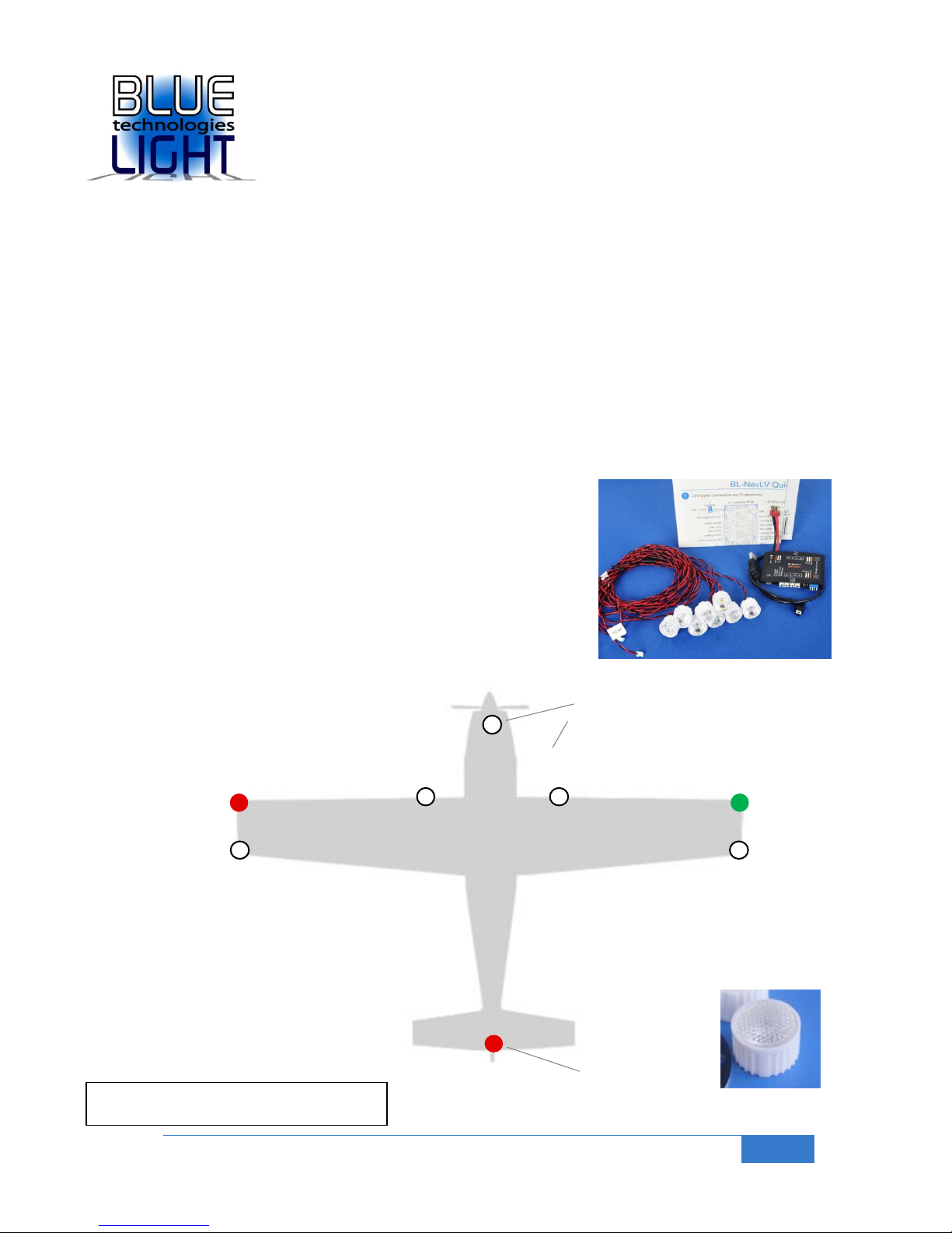
Nav light
(constant on)
Nav light
(constant on)
Strobe Nav light
(blinking on/off)
Landing light
(constant on)
Strobe Nav light
(blinking on/off)
Landing light
(constant on)
Landing light
(constant on)
Underneath
Forward facing
Beacon light
(blinking on/off)
On top of
aircraft fin
Super-Bright Navigation / Landing Lights with
Low Battery Detect Modes / RC in & out
and Redundant Battery Connect / Clean BEC
_______________________________________________________________________________________________________
BL-NavLV-S
____________________________________________________________________________
Features
8 (1W) LEDs for Navigation, Landing & Beacon lights. Two modes:
o Super bright mode (Approx. / Average 100 lumens per LED)
o High brightness mode (Half brightness)
o Supports up to 11 LEDs * in super brightness mode
Professional double blink strobe for rear Nav and strobe lights
Li-Poly Low battery detection. Two modes:
o Voltage monitor (selectable number of cells)
o Time-out (selectable time periods)
o Activation on first of above to occur option
Low Battery warning:
o Special LED blinking sequence (+ on board Red LED)
o RC connector output pulse (for external system use, such as
parachute)
Li-Poly 1, 2, 3, 4, 5 or 6 (series) cells supported (up to 26v)
RC Rx input to switch on / off
o Landing lights activated coincident with landing gear
o 2 way or 3 way RC switch supported
RC Output (battery redundancy)
o RC Rx back up power (BEC function to 4A burst)
o Activation of external system in case of low battery
Right out of the box use for easy in-field set up
o On board DIP switches (PC status tool also available)
Optional operation from external 5v, or 9v (up to 26v) supply
Operational temperature: -30 0C to +85 0C
RoHS, “green” compliant
Applications
UAV / UAS / FPV / RC Airplane
Multi-copter and hybrid Aircraft
RC Helicopter
Size, power and weight
80 x 50 mm controller unit
8 x LEDs with 1m (39”) cables supplied
19mm star configuration LEDs + lenses
Typical power used < 10W (x 8 LEDs)
All up weight is 87g (45g controller only)
Total Power output 30+ Watts
See more details at:
www.bluelight-tech.com/BL-NavLV-S.htm
_______________________________________________________________________________________________________
User Manual
Can support x 2 LEDs per each
flashing output
- 11 LEDs in total !
* 8 LEDs supplied, can double up blinking LEDs if required
X 8 beaded lenses for authenticity
and LED protection
Page 2
Bluelight Technologies Co. Ltd. | BL-NavLV User Manual V1.0
2 of 21
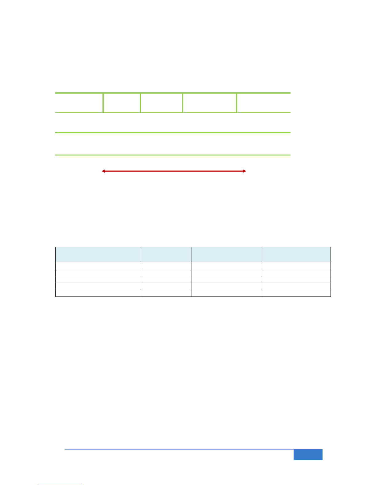
Standard
Ultra-bright
(or high-bright)
LED Type :
Super-bright
Power (W) :
Indication
High power
High temperature
High cost
Low Power
Low temperature
Low Cost
0.05 0.5 ~ 1.5 0.20.1
Brightness :
0.03 ~ 0.1 cd
0.1 ~ 0.15 cd
100+ (lm)
8 ~ 50 cd
LED types
Note on Brightness
Brightness terms used in this manual:
cd : Candela (A common candle is roughly 1 candela)
lm : Lumen (A metal halide lamp, ie conventional indicator / break lights of cars is around 100 / 200
lm)
W : Watt (Electrical power level. 1W = 0.3A at 3.3V)
Approximate luminous flux comparisons for a ‘reasonable’ view of the light:
Application
Luminous flux
Viewable distance
(day-time)
Viewable distance
(night-time)
A typical common candle
1 cd
50 feet
100 feet
Ultra or high brightness LEDs
11,000 cd
100 feet (daytime)
400 feet
Car metal halide indicator bulb
100 lm
400 feet (daytime)
1 mile
Car headlight
1,000 lm
1 mile
5 miles
Good HID car headlight
3,000 lm
1 mile +
5 miles +
Note that these figures are rough and for indication only. After all it is claimed by scientists, in an experiment
performed back in 1941, that the human eye can see a candle flame flickering at night up to 30 miles away !!!
(It only takes between 5 to 14 photons for the brain to register that it’s seeing something).
The brightness you get clearly has an impact on the current drawn from the battery. See section
6.0 of this manual for more information.
Page 3
Bluelight Technologies Co. Ltd. | BL-NavLV User Manual V1.0
3 of 21
Nose
Front inner starboard wingFront inner port wing
Back of fin
Starboard wing tip 1
Starboard wing tip 2
Port wing tip 1
Port wing tip 2
Micro-
processor
3.3v to 24v
(1s to 6s)
T
connector
USB 2.0
RC output (For servo switching
and RC Rx 5v back up power)
RC Rx input (on / off)
PCB
LED
connect
LED
connect
1m twisted pair
Ultra bright LED
LED
Driver
Wafer right angle
2.0mm connector
DIP1
1
4
DIP2
4
1
LEDs
Ext supply (5v ~ 24v)
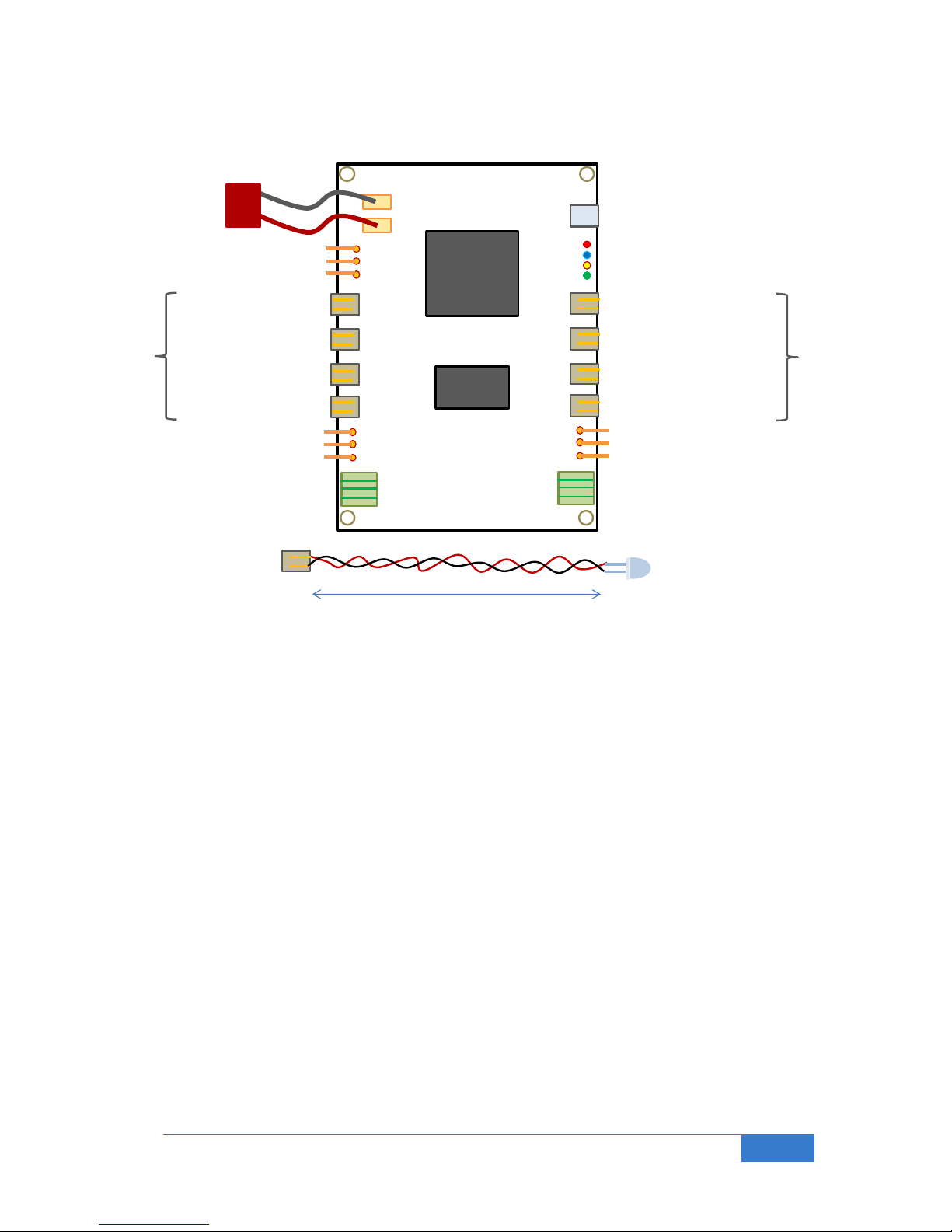
1.0 Block Diagram
The PCB consists of the following connections:
Main Li-Poly T connector for 1s to 6s battery connection (Black is ground)
External supply for connection of, for example, a 9v battery
x8 LED outputs (supports x2 LEDs per output)
RC Rx input for on/off lights switching
o Nav and Landing lights on / Nav lights only on : 2 way Rx Tx switch
o Nav and Landing lights on / Nav lights on / All lights off : 3 way Rx Tx switch
RC output for on/off of external device such as a parachute system or throttle cut-off
x2 DIP switches for functionality setting (See section 2.0)
Red
Red*
White*
White
White
White
White*
Green
* flashing
Page 4
Bluelight Technologies Co. Ltd. | BL-NavLV User Manual V1.0
4 of 21
5
1
4
3
2
8
7
6
14
10
12
11
15
9
13
16
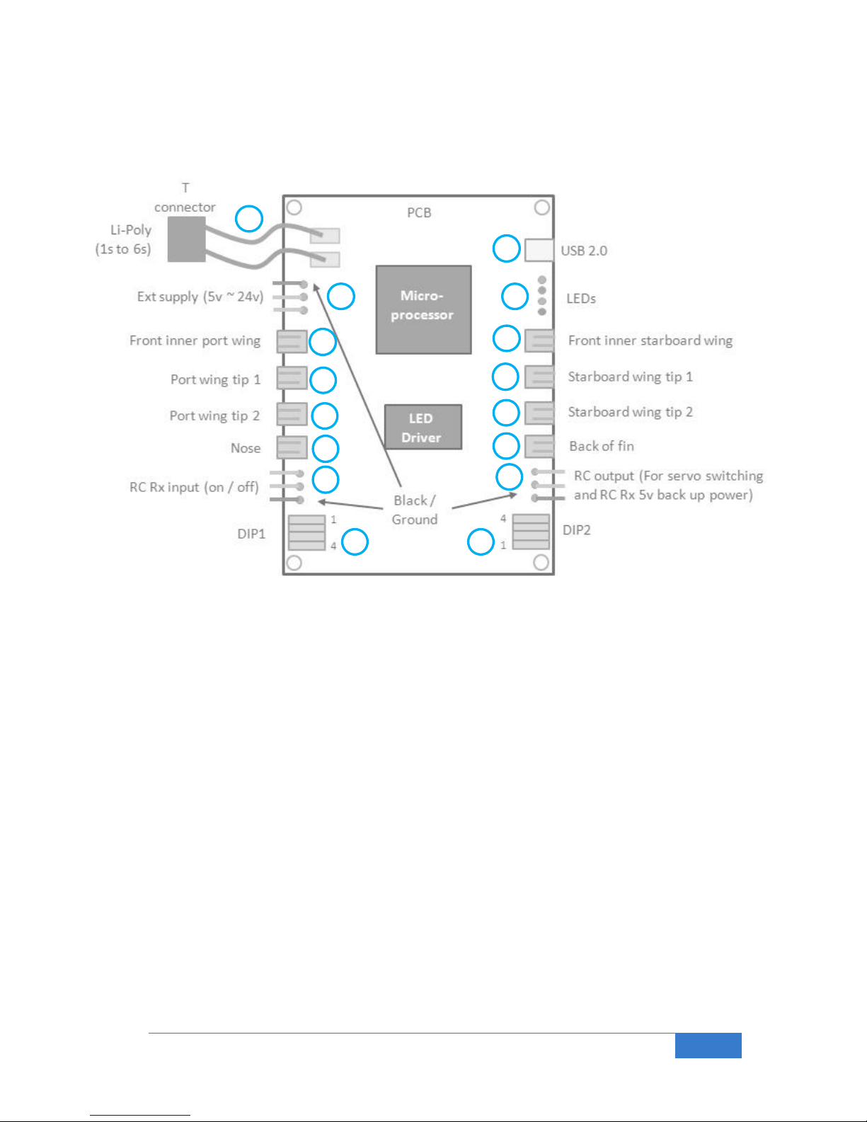
2.0 Connection and Switches
Connection is easily achieved by following the 16 steps here:
(1) Connect the main Li-Poly battery here, maximum of 6 cells in series (6s).
(2) If you plan to use the low voltage detect function it is advisable to connect an external power
supply here. We suggest a standard 9V battery. Note that ground is on the T connector side of
the PCB, and the voltage in the middle pin. This interface can take any voltage from 5v up to
26v. (Note that if this input voltage is less than the main LiPo voltage, the unit will not take
power from it until the LiPo battery is flat. Conversely if the voltage is higher than the LiPo
battery voltage the unit will be powered only from this input).
(3) If you wish to connect an RC Rx signal in here you can. The default is to have all the LEDs
active, but you can have the option to switch on / off as shown here:
a. Nav lights only / All lights on : 2 way Rx Tx switch
b. Nav lights only / All lights off / All lights on : 3 way Rx Tx switch
Note that with no connection as per step (2), and Li-Poly battery drained the PCB will take
power from this connector if necessary.
(4) If you would like something to happen when the battery has been detected as being low you
can connect this RC output signal (between 1ms and 2ms with 15ms period at 5v) to an
external device, such as a parachute deployment servo. (The on / off level can be inverted with
the DIP2). Note that if you have a battery connected as per step (2) this will serve as an RC Rx
power supply (BEC) in case of main Li-Poly battery failure (5.2v nominally).
(5) We provide a USB2.0 for firmware upgrade for future operationally different solutions to run on
the same PCB. Please visit our website to check up on availability of different firmware. (Not
needed for normal operation of this product).
(6) thru to (13) connect up the LEDs to the locations as shown on the front cover diagram.
Page 5

Bluelight Technologies Co. Ltd. | BL-NavLV User Manual V1.0
5 of 21
(14) DIP1: Select the set-up options you would like to implement on DIP1:
The BL-NavLV can be used to output a special sequence of flashes on all the LEDs to show that
the battery is running low. This can be achieved with either the BL-NavLV checking the battery
(LowVBat Mode) or by setting a time period after which you would like the LED indication to
happen (LowVtime Mode). If both options are set the low battery LED sequence will be initiated
when the first of these conditions is met.
Switches 1, 2 and 3 are used to select the number of cells you have in your Li-Poly battery. If these
switches are all set to off it means the detection of a low voltage in LowVBat Mode is disabled.
SW 1, SW2, SW3
off off off : LowVBat Mode Off
off off on : 1 cell
off on off : 2 cells
off on on : 3 cells
on off off : 4 cells
on off on : 5 cells
on on off : 6 cells
on on on : LowVtest
If all switches are set to on the LEDs will flash in the low battery test pattern so as to familiarize the
RC pilot with the flashing sequence when a real low battery condition is met.
(15) DIP2: Select the set-up options you would like to implement on DIP2:
Switches 1, 2 and 3 are used to select the time before the low battery level LowVtime Mode is
activated. If these switches are all set to off it means the detection of a low voltage in LowVtime
Mode is disabled.
SW1, SW2, SW3
off off off : LowVtime Mode Off
off off on : 10 minutes
off on off : 15 minutes
off on on : 20 minutes
on off off : 30 minutes
on off on : 40 minutes
on on off : 50 minutes
on on on : 60 minutes
(16) Verification of correct operation is achieved by checking the PCB LEDs
RED LED : LiPo below safe operational level when flashing on / off (LiPo damage may result)
LiPo below very low level when constantly on (see last page of this document)
BLUE LED : System micro up and running (flashing on / off), otherwise off
YELLOW LED : LowVBat Mode selected: Flashing, longer time on than off
: LowVtime Mode selected: Flashing, longer time off than on
: Both LowVBat and LowVtime Modes selected: Symmetrical flashing
: Test low battery alarm sequence: Fast symmetrical flashing
: Only LED mode (no battery monitoring): Off
GREEN LED : Super LED brightness mode (Bright Mode1) selected when on
: High LED brightness mode (Bright Mode2) selected when off
Note that these LEDs are tested once at system power up.
SW4
on : Bright mode 1 (Super brightness)
off : Bright mode 2 (High brightness)
SW4
off : RC out invert off (max pulse when low bat)
on : RC out invert on (min pulse when low bat)
Note: DIP2 SW4 also inverts the RC In function
Note: Any time between 5 mins and 4 hrs can be set using
PC tool and advanced commands (see section 7.6.1)
Page 6
Bluelight Technologies Co. Ltd. | BL-NavLV User Manual V1.0
6 of 21
1
4
2
Main battery
Small 9v bat
RC
Rx
Servos
ESC
Battery Y cable
11 v
9 v
1
4
2
Small 9v bat
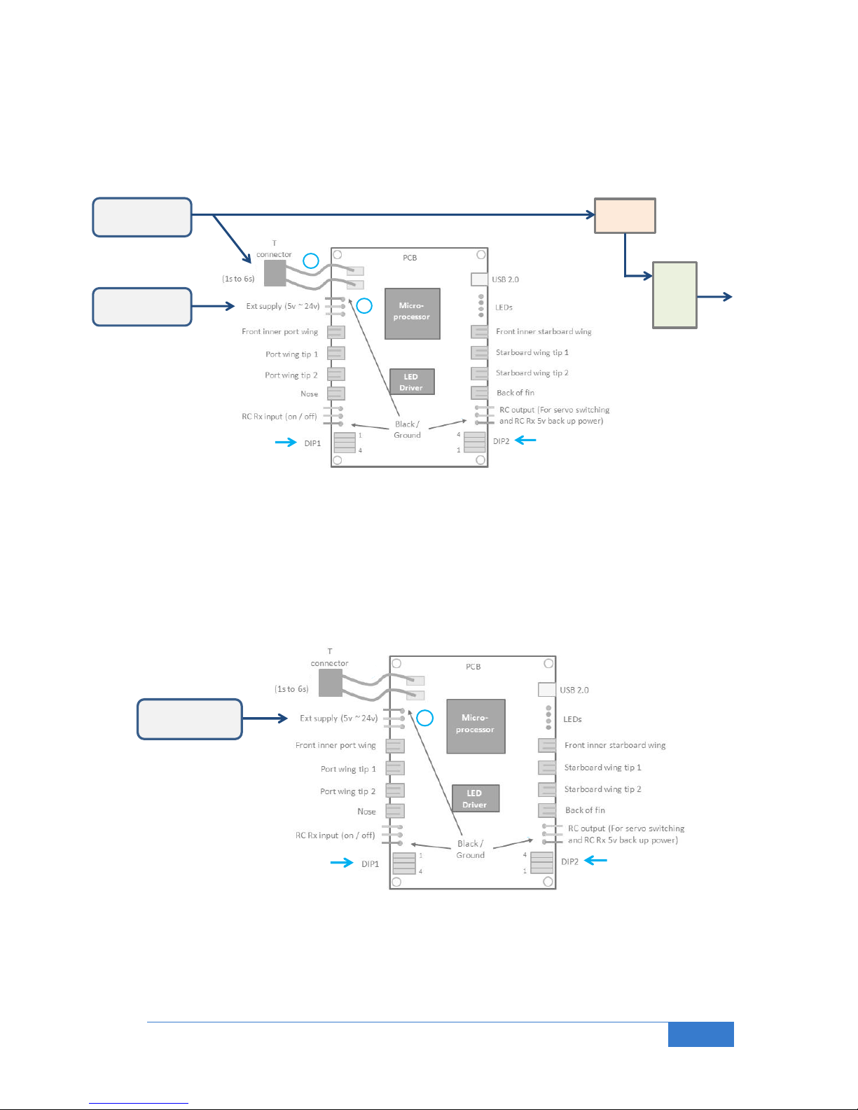
3.0 Example Connections for Electric Aircraft
3.1 Typical Connection (In low Voltage Detect Mode)
With this connection the battery low detect works on measuring the actual voltage on the main battery.
(1) Connect the main Li-Poly battery here, maximum of 6 cells in series (6s).
(2) Connect a small 9v battery here to power the LED/NAV PCB in case of main battery failure.
Set DIP1 to the number of cells in your battery. For 3 cells, 1:off, 2:on, 3:on, and 4:on for super bright
Set DIP2 to all off
3.2 Nav LED Connection Only (No low battery indication)
No voltage detect or timer. Only LED Nav lights operational
(2) Connect only a battery or supply (typically 9v battery, or 5v / 6v supply in here)
Set DIP1 to 1~3: off, and 4:on for super bright, or off for high brightness
Set DIP2 to all off
Page 7
Bluelight Technologies Co. Ltd. | BL-NavLV User Manual V1.0
7 of 21
1
4
2
Main battery
Small 9v bat
RC
Rx
Servos
ESC
Battery Y cable
11 v
9 v
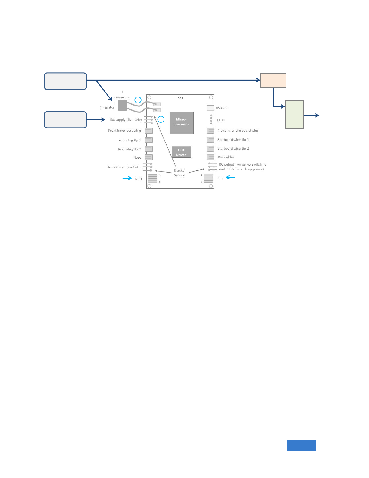
3.3 Typical Connection (In Time Out Detect Mode)
With this connection the battery low detect works on a fixed time elapsing after being powered up.
(1) Connect the main Li-Poly battery here, maximum of 6 cells in series (6s).
(2) Connect a small 9v battery here to power the LED/NAV PCB in case of main battery failure.
Set DIP1 to 1~3: off, and 4:on for super bright, or off for high brightness
Set DIP2 to the time-out time duration, eg for 20 minutes: 1:off, 2:on, 3:on, 4: off.
3.4 Typical Connection (In Low Voltage AND Time Out Detect Modes)
It is possible to have the BL-NavLV perform its low voltage detect flashing sequence on whichever of the
two events happens first: The detection of a low voltage on the main LiPo battery or a flight duration
greater than a pre-set value.
The connection is the same as in 3.3 above but the DIP switches must be set up for both detect modes:
Set DIP1 to the number of cells in your battery. For 3 cells, 1:off, 2:on, 3:on, and 4:on for super bright
Set DIP2 to the time-out time duration, eg for 20 minutes: 1:off, 2:on, 3:on, 4: off.
Page 8
Bluelight Technologies Co. Ltd. | BL-NavLV User Manual V1.0
8 of 21
1
4
2
Main battery
RC
Rx
Servos
ESC
Battery Y cable
5v
Spare battery
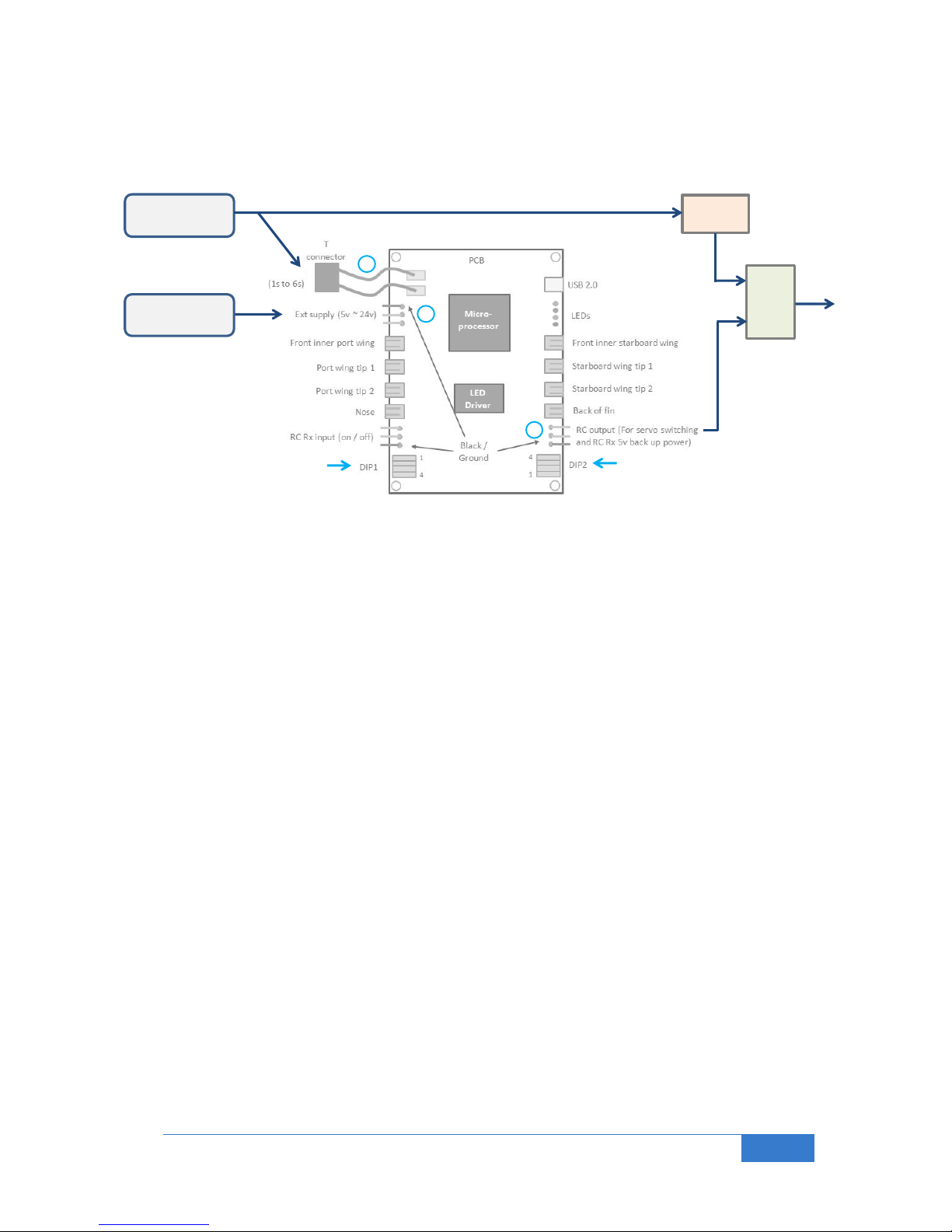
3.5 Battery Redundancy (For Servos and RC Receiver)
By having two LiPo batteries connected if one battery goes down (eg main battery below the voltage of the
spare battery), no current will be taken out of it. Instead power will be taken from the good battery instead.
(1) Connect the main Li-Poly battery here, maximum of 6 cells in series (6s).
(2) Connect a secondary Li-Po battery here. If main battery goes down the second one will power the
system, including the RC Rx and servos
(4) Connect to RC Rx battery input or to any of the RC Rx unused outputs (MUST use a two wire cable for
power / ground, ie with NO signal wire).
Note the BL-NavLV can supply 3A of continuous current (4A burst) from the spare battery to the RC output
connector and onto the RC Rx and servos (BEC function). This is normally adequate for most multi-servo
aircraft, but for larger multi-servo aircraft the servo power requirements should be checked.
Set DIP1 to the number of cells in your battery. For 3 cells, 1:off, 2:on, 3:on, and 4:on for super bright
Set DIP2 to 1~3: off, and 4:on to trigger chute with low RC signal, or off, to trigger on high RC signal
Page 9
Bluelight Technologies Co. Ltd. | BL-NavLV User Manual V1.0
9 of 21
1
4
2
Main battery
RC
Rx
Servos
ESC
Battery Y cable
5v
Parachute
servos
Small 9v bat
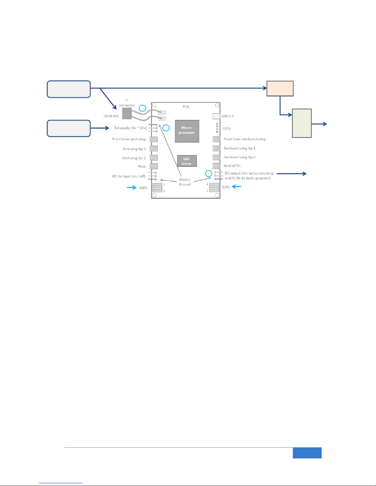
3.6 Parachute Deployment Mode (If battery low detected)
If the main battery goes low, a parachute servo is deployed via the RC output connection.
(1) Connect the main Li-Poly battery here, maximum of 6 cells in series (6s).
(2) Connect a small 9v battery here to power the LED/NAV PCB and parachute servo in case of main
battery failure.
(4) Connect a small deployment servo here (the RC output can support 3A current, so this will be no
problem).
Set DIP1 to the number of cells in your battery. For 3 cells, 1:off, 2:on, 3:on, and 4:on for super bright
Set DIP2 to all off
Page 10
Bluelight Technologies Co. Ltd. | BL-NavLV User Manual V1.0
10 of 21
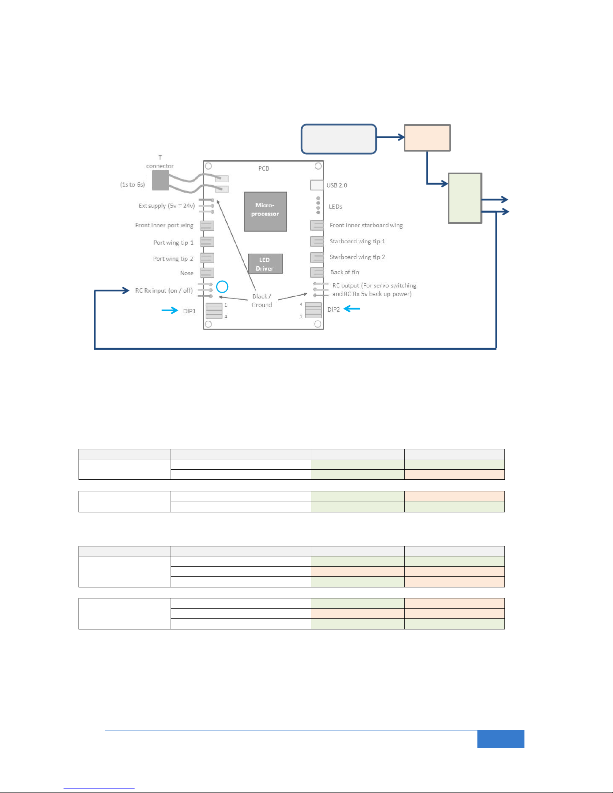
3
Main battery
RC
Rx
Servos
ESC
Optional Y cable
for Landing gear
On / off
Gear
3.7 Nav / Landing Lights On / Off (With Optional Low Battery Detect Time Mode)
Simple connection to allow Nav. / Landing lights to be switched on and off as required. Note that if a Y cable
is used the Landing lights can be switched on co-incident with the landing gear being deployed.
(3) Connect the RC Rx output to the RC Rx input (on / off) connector. The BL-NavLV will take power from
this connector if no other battery is connected to it.
Set DIP1 to 1~3: off, and 4:on for super bright, or off for high brightness
Set DIP2 to 1~3: off, and 4:off, for normal RC Tx switch operation or on for inverse as shown here:
If you have a TWO way switch on your transmitter:
DIP 2 SW 4 position
RC Tx switch
Nav lights
Landing lights
Off
On (High pulse output)
On
On
Off (Low pulse output)
On
Off
On
On (High pulse output)
On
Off
Off (Low pulse output)
On
On
If you have a THREE way switch on your transmitter:
DIP 2 SW 4 position
RC Tx switch
Nav lights
Landing lights
Off
On (High pulse output)
On
On
Mid (Mid pulse output)
Off
Off
Off (Low pulse output)
On
Off
On
On (High pulse output)
On
Off
Mid (Mid pulse output)
Off
Off
Off (Low pulse output)
On
On
Note, if you wish to display the low battery flashing sequence after a set period of time simply:
Set DIP2 Switches 1~3 to the time period, eg for 20 minutes: 1:off, 2:on, 3:on.
Page 11
Bluelight Technologies Co. Ltd. | BL-NavLV User Manual V1.0
11 of 21
1
3
RC
Rx
Servos
ESC
RC Rx bat
Main battery
Battery Y cable
Optional Y cable
for Landing gear
On / off
Gear
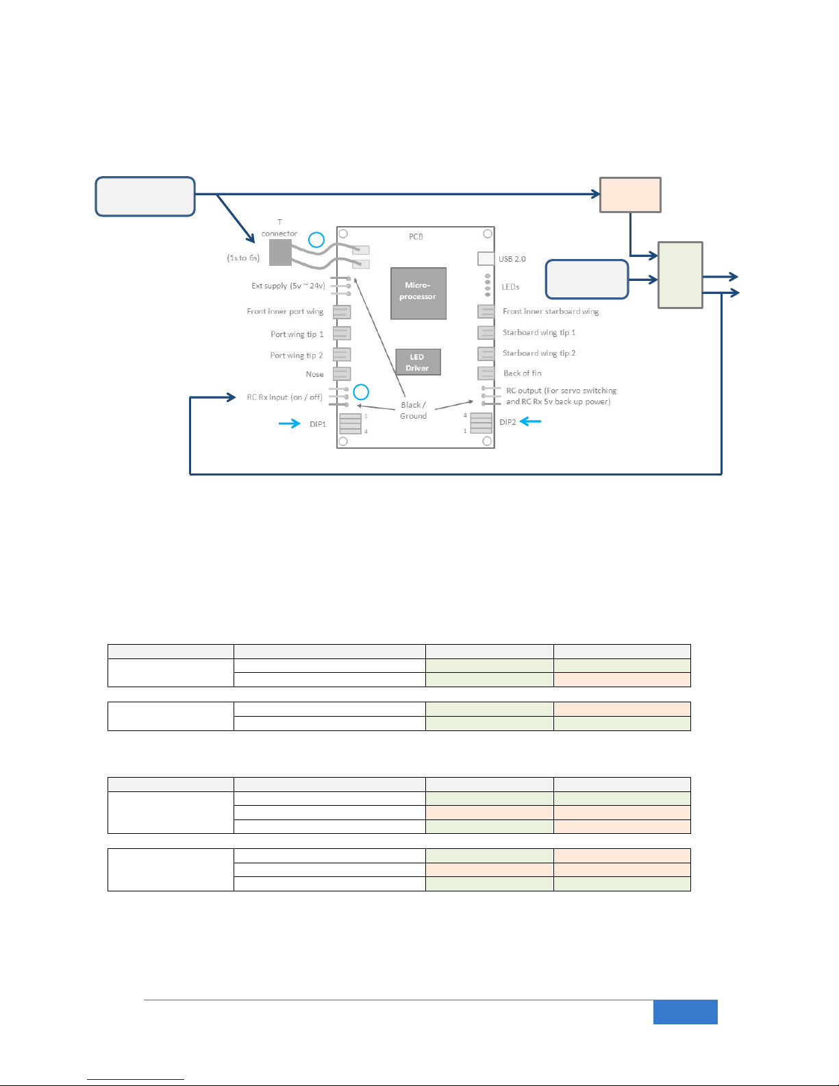
3.8 Nav / Landing Lights On / Off (In low Voltage Detect Mode)
Simple connection to allow Nav. / Landing lights to be switched on and off as required. Note that if a Y cable
is used the Landing lights can be switched on co-incident with the landing gear being deployed.
(1) Connect the main Li-Poly battery here, maximum of 6 cells in series (6s).
(3) Connect the RC Rx output to the RC Rx input. The BL-NavLV will take power from this connector if no
other battery is connected to it. Note the optional RC Rx bat connected to the RC Rx. If the main LiPo
battery goes down it may go down very quickly.
Set DIP1 to 1~3: off, and 4:on for super bright, or off for high brightness
Set DIP2 to 1~3: off, and 4:off, for normal RC Tx switch operation or on for inverse as shown here:
If you have a TWO way switch on your transmitter:
DIP 2 SW 4 position
RC Tx switch
Nav lights
Landing lights
Off
On (High pulse output)
On
On
Off (Low pulse output)
On
Off
On
On (High pulse output)
On
Off
Off (Low pulse output)
On
On
If you have a THREE way switch on your transmitter:
DIP 2 SW 4 position
RC Tx switch
Nav lights
Landing lights
Off
On (High pulse output)
On
On
Mid (Mid pulse output)
Off
Off
Off (Low pulse output)
On
Off
On
On (High pulse output)
On
Off
Mid (Mid pulse output)
Off
Off
Off (Low pulse output)
On
On
Note, if you wish to display the low battery flashing sequence after a set period of time simply:
Set DIP2 Switches 1~3 to the time period, eg for 20 minutes: 1:off, 2:on, 3:on.
Default with no input is all lights enabled
Page 12
Bluelight Technologies Co. Ltd. | BL-NavLV User Manual V1.0
12 of 21
1
4
2
3
Main battery
RC
Rx
Servos
Spare battery
Gear
5v
2
3
RC
Rx
Servos
RC Rx bat
On / off
Small 9v bat
Option
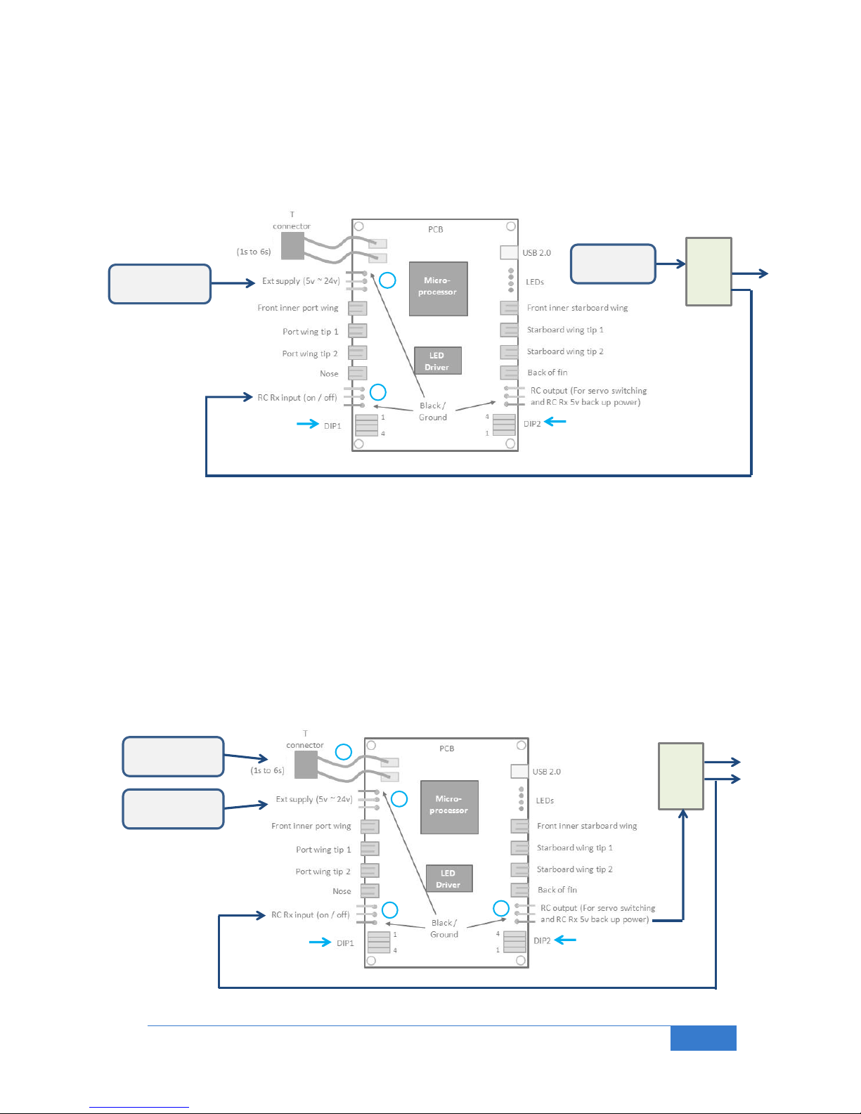
4.0 Example Connections for Gas Aircraft
4.1 Fuel Low based on Flying Time Detect Mode
The Low Voltage Detect flashing sequence can be initiated for gas aircraft simply based on the flying time.
The flight duration is used in this mode so this can be assumed to indicate a low fuel condition.
(2) The small 9v (or any 5v~26v) battery is an option if you don’t want to drive the unit from the main supply
(via the on/off switch in the example shown above).
(3) Connect an input from your RC Tx switch such as on / off, or gear down or any spare switch.
Set DIP1 to 1~3: off, and 4:on for super bright, or off for high brightness
Set DIP2 to the time-out time duration, e.g. for 30 minutes: 1:on, 2:off, 3:off, 4: off.
4.2 Redundant Battery with Low Battery Voltage Detect Mode and Lights on/off
Connection with spare battery and detect if main battery goes low. Also shown is connection of
lights switch.
Page 13

Bluelight Technologies Co. Ltd. | BL-NavLV User Manual V1.0
13 of 21
(1) Connect the main LiPo electronics battery here, minimum 5v, maximum 12v.
(2) Connect a secondary battery here. If main battery goes down the second one will power the system,
including the RC Rx and servos
(3) Connect an input from your RC Tx switch such as gear down (via Y cable), or any spare switch
(4) Connect to RC Rx battery input or to any of the RC Rx unused outputs (MUST use a two wire cable for
power / ground, ie with NO signal wire).
Note the BL-NavLV can supply 3A of continuous current (4A burst) from the spare battery (or main LiPo
battery, whichever is the greater voltage) to the RC output connector (4) and onto the RC Rx and servos.
This is normally adequate for most multi-servo aircraft, but for larger multi-servo aircraft the servo power
requirements should be checked.
Set DIP1 to the number of cells in your battery. For 2 cells, 1:off, 2:on, 3:off, and 4:on for super bright
Set DIP2 to all off.
5.0 Low Volt (LowVBat Mode) or Time out (LowVtime Mode) flashing sequence
The unit can be tested to see the warning (either LowVBat Mode or LowVtime Mode) flashing sequence by
setting:
DIP1 to all on.
The sequence for all LEDs is:
Sleep 2s, on 200ms, off 240ms, on 200ms, off 240ms, on 200ms, and repeat
(Note, if a 3 way switch is used, the all LEDs off position will also switch this test sequence off)
6.0 Battery Requirements
6.1 Simple 9V Battery
The BL-NavLV requires around 10 Watt of power to operate (Assuming it doesn’t power any external RC Rx
or servos). Hence a 9v battery (typically with 550 mAh rating) will last for:
0.55 / (10 / 9) = 30 mins. with LEDs in super bright mode.
6.2 Small 2s LiPo Battery
With a 7.4v 2s, 1000 mAh LiPo will last for:
1.0 / (10 / 7.4) = 45 mins. with LEDs in Super bright mode (35 mins. running battery to 80% charge)
6.3 Medium 3s LiPo Battery
With an 11.1v 3s, 2200 mAh LiPo will last for:
2.2 / (1 / 11.1) = 2.4 hours with LEDs in Super bright mode (2 hours running battery to 80% charge)
Note: Running in the lower brightness mode will reduce the power consumption by
approximately a factor of 6 (six).
Page 14
Bluelight Technologies Co. Ltd. | BL-NavLV User Manual V1.0
14 of 21
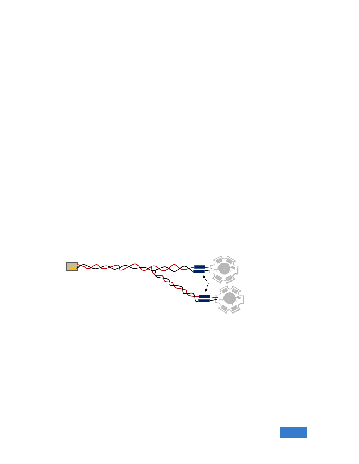
Resistors
Super bright LED
Second LED
7.0 Advanced Features
7.1 Snooze Mode
When you’re flying and the alarm for low battery activates (either via the time-out mode or the low LiPo
battery voltage detection), it may be that you wish to have the Navigation and Landing lights operate as
normal for the landing: Simply move the switch to a new position and the alarm sequence will be disabled for
a period of 5 minutes (by default). This parameter can be changed via the advanced commands, see section
7.6.1. Note that when Snooze mode exits, the warning flashing sequence will again be activated if you were
in time-out mode, or in low voltage detect mode, if the low battery condition is still present.
If you do not wish to toggle a switch to disable the alarm flashing sequence you can have the BL-NavLV
automatically do this for you after a certain time (10 seconds by default). You can program this Auto Snooze
feature via the advanced commands, or if you don’t wish to connect to a PC you can also program this in the
following way:
1) Remove all power to the BL-NavLV unit, and set the DIP switches of both DIP 1 and DIP 2 to all ON
2) Power up the BL-NavLV, then set the DIP switches to your normal desired positions.
(If you wish to change the Auto Snooze time from the 10s default, you will again need to refer to the
advanced commands (SzAT) in section 7.6.1).
To again de-activate this Auto Snooze mode feature simply repeat the above but with all DIP 1 and DIP 2
switches to OFF prior to power on.
7.2 Connection of more LEDs (ONLY for flashing LEDs or one constant on LED)
For pilots interested in specific configurations it is possible to connect another LED in parallel. This is
achieved by simply connecting another LED in parallel to an existing one with your own special cable. For
example you may wish to add an additional white navigation light on the tail. No more than one additional
LED per output otherwise damage may occur to the PCB. Any additional LEDs will operate at the same
brightness level as the originals.
Additional sets of LEDs and connectors can be bought from bluelight-tech.com website.
Page 15

Bluelight Technologies Co. Ltd. | BL-NavLV User Manual V1.0
15 of 21
7.3 LED lead lengths changes
The length of the twisted pair cables can be reduced or increased as desired. There is no real practical limit
to the length, but we suggest no longer than 4 meters.
7.4 Alternative Connections
It is perfectly safe to swap LEDs, i.e. any LED can be plugged into any controller board LED output
connector.
7.5 Operation with LiPo batteries larger than 6 cells
If you have more than 6 cells, you can still use the BL-NavLV with all its features. Each LiPo has a balance
connector which outputs the voltage on each of its internal cells. You can make up a special cable to allow
just one of the cells’ voltage to be monitored (one cell connection + ground). Then set the BL-NavLV up with
1 cell selected on DIP1. You will also need to supply an alternative power source to the BL-NavLV, such as
5v or higher into the Ext Supply input or into the RC Rx input.
Page 16
Bluelight Technologies Co. Ltd. | BL-NavLV User Manual V1.0
16 of 21
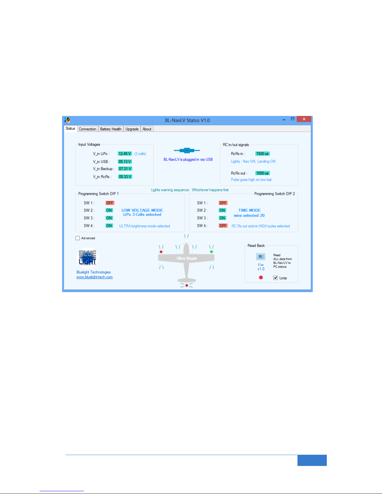
7.6 Optional PC Status and Advanced Set-up Tool
If you wish to check the status of the BL-NavLV unit, including voltage levels of batteries you connect to it
you can use the PC status software. It will also aid in setting up the unit to your exact requirements. Supports
Windows platforms only (XP, Vista, 7 and 8). Runs on 64 bit machines (in 32 bit mode). Requires .NET
framework.
The tool is available free from the bluelight website (www.bluelight-tech.com).
The main Status screen is shown here for information.
USB / PC Status tool – Status tab
The aircraft graphic lights will actually blink as the real BL-NavLV will operate if connected via USB and set in
loop mode (constantly getting data from the BL-NavLV module). Hence the complete system can be checked
out via USB prior to connecting any real LEDs.
Please take care to ensure an external power source is connected to the BL-NavLV controller board
(if the LEDs are connected) prior to plugging into the PC USB port. Due to limited power output from
the USB port incorrect functionality can occur.
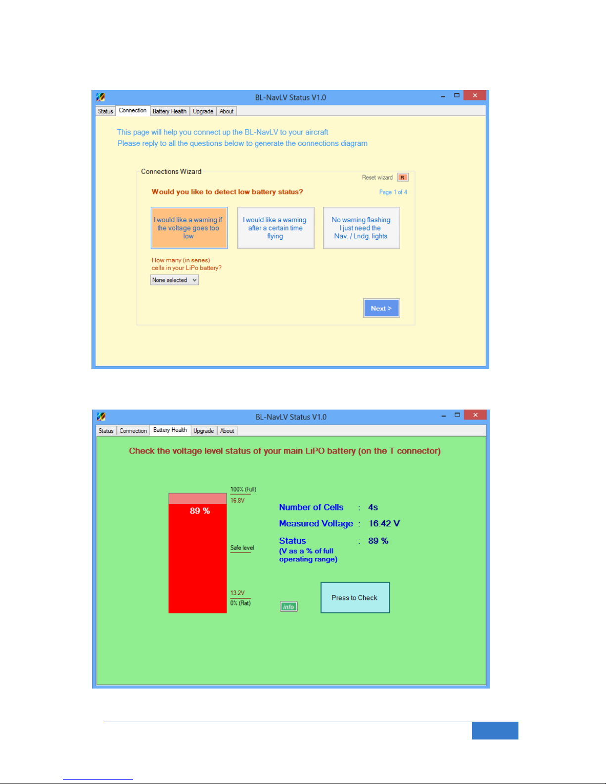
Two further tools you may find useful are also provided as shown on the next page.
This tool will be updated to allow further changes in the future. Hence an upgrade tab page is also provided
to allow the BL-NavLV firmware to be upgraded as required. Please see our website for more details.
Page 17
Bluelight Technologies Co. Ltd. | BL-NavLV User Manual V1.0
17 of 21
Other tools that may be of interest are as shown here:
USB / PC Status tool – Connection Wizard tab
USB / PC Status tool – Battery Health tab
Page 18
Bluelight Technologies Co. Ltd. | BL-NavLV User Manual V1.0
18 of 21
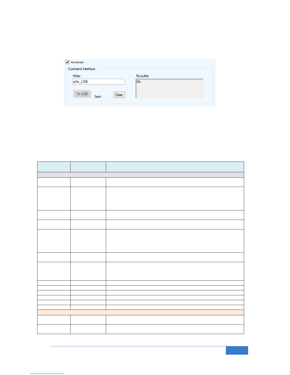
7.6.1 Optional PC Status Tool – Advanced Commands
At the bottom left of the Status tab page you will see an advanced check box option. Clicking this makes the
following screen visible:
This is the command interface. Certain functionality of the BL-NavLV unit can be customized with special
commands. Also status commands can be sent to glean specific information from the unit.
If information is to be written into the unit the following command format is to be used:
To set a parameter: e.g. for the V_trig command : V_trig = 3.41;
To read back a parameter, e.g. for V_trig : qV_trig; (response is V_trig = 3.4100;)
Set
Command
Query
command
Comments
PC tool Advanced Commands
V_trig
qV_trig;
Sets / reads back the low battery level (per cell) to trigger the low battery
flashing sequence (default 3.4V per cell).
T_trig
qT_trig;
Sets / reads back the time delay (in minutes) prior to triggering the low
battery flashing sequence. (If programmed to a value between 5 and 240
minutes it will override the values obtained via the on board switches). If
previously set up can set to 0 to cancel. (BL-NavLV PCB switches MUST
be set in LowVtime mode)
PWM_period
qPWM_period;
Sets / reads back the output PWM period in us (default 15000us). Practical
limits should be between 20000us and 1400us
Hyst
qHyst;
Sets the hysteresis in the trigger point detect voltage (limits 0 to 10% of the
single cell low voltage trigger level). Default is 1%
SzTime
qSzTime;
Sets / reads back the time (in seconds) the low battery alarm flashing
sequence is temporarily disabled after entering snooze mode. The alarm
will again be activated on exit if set on a time out, of if set on a low voltage
detect, only if the low voltage condition is still present. (Default is 5
minutes)
SzAuto
qSzAuto;
Sets / reads back the Automatic Snooze function setting. 1 if set (enabled)
0 if not
SzAT
qSzAT;
Sets / reads back the Automatic Snooze function timer. I.e the Alarm
flashing sequence will automatically be disabled after this time (in seconds
– default is 10 seconds). Note it will come on again after SzTime seconds.
Limits are between 1 second 10 minutes (600 seconds)
n/a
qAlarm;
Reads back the Alarm status (1 if alarm has been set)
n/a
qSnooze
Reads back if the unit is in Snooze mode (1 if yes)
n/a
qVin_LiPo;
Reads back the T connector connected battery voltage level
n/a
qVin_USB;
Reads back the USB voltage level
n/a
qVin_Backup;
Reads back the backup connected battery voltage level
n/a
qVin_RcRx;
Reads back the RCRx connected battery voltage level
PC tool System Commands
EERASE
n/a
Erases the entire EEPROM contents (set to factory defaults at new power
up)
AlarmDis
n/a
Temporarily disables the flashing alarm completely (need to power cycle to
enable again)
Page 19
Bluelight Technologies Co. Ltd. | BL-NavLV User Manual V1.0
19 of 21
8.0 LiPo Battery low Warning Trigger Level
LiPo batteries consist of multiple single cells (3.7 V) connected together in series. This discussion therefore
focuses on a single cell case. It is then an easy matter to just multiply the numbers up depending on how
many cells you actually have in your LiPo battery.
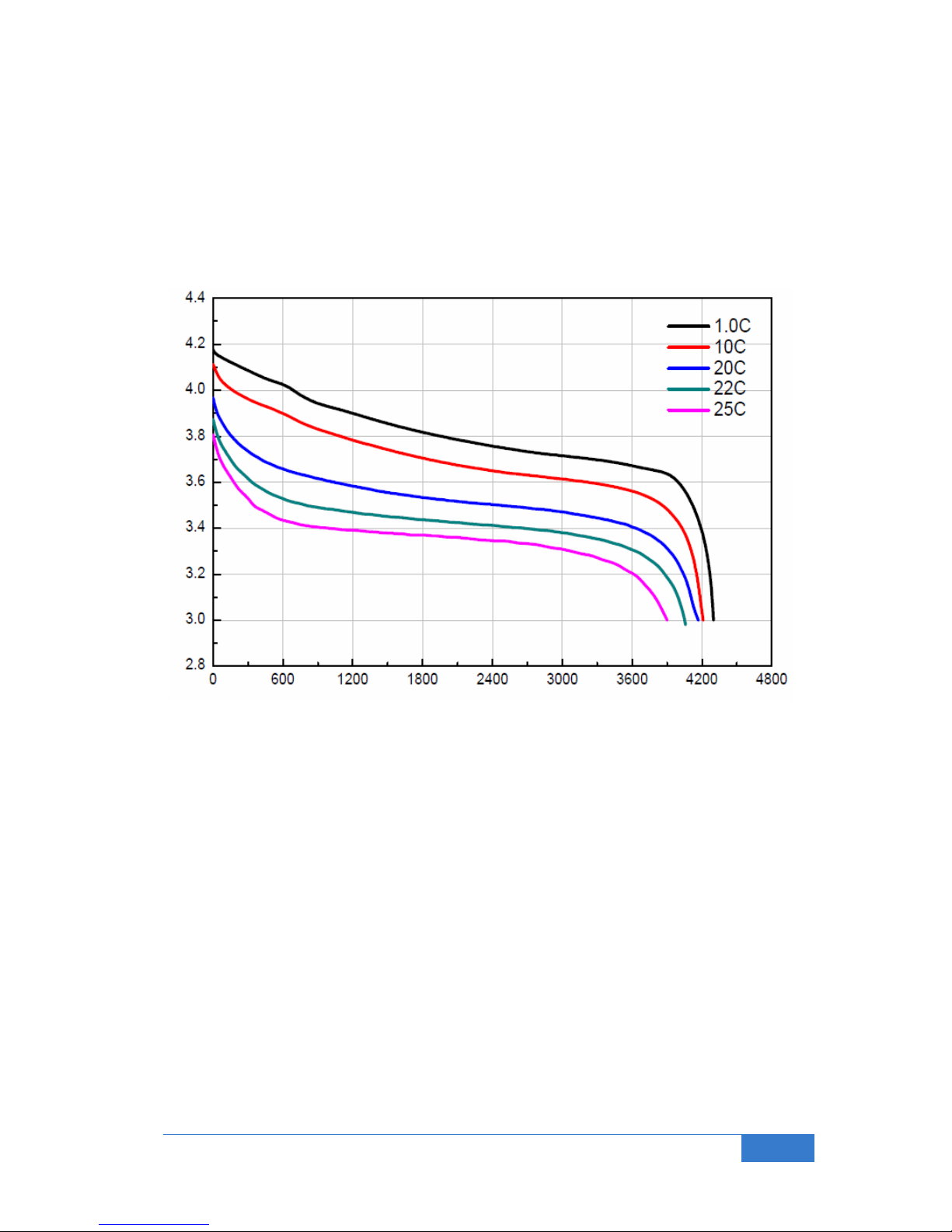
LiPo batteries have different discharge characteristics depending mainly on the C rating, but also on the
operational temperature, and to a certain extent on the manufacturer. A typical chart of the voltage level of
the cell and the charge remaining is shown here for a particular 4200mA battery:
As you see, the cell capacity goes down, almost to a plateau, then falls off sharply at the right hand side
“Knee” as the voltage falls. So typically the LiPo can be charged up to about 4.2v and discharged down to
around 3V. However the battery will always have a minimum discharge level. In other words, a level where
you must not discharge the battery further otherwise the battery will become damaged and no longer able to
retain its full charge after the next charge cycle. A typical number talked about is to run the battery down to
20% charge remaining, i.e. to use only 80% of its total charge. However each individual has his or her own
preference for a multitude of reasons.
The BL-NavLV has by default a level of 3.4V as the level at which a warning is issued (special LED flashing
sequence, and controller PCB red LED flashing). This 3.4V per cell threshold can be changed with the BLNavLV PC tool to any voltage level desirable. See section 7.6.1 above. Once a trigger condition has been
found the normal LED operation will only be started again after the voltage rises to at least the trigger level +
a hysteresis value, which by default is set to 1% of the trigger level (so at 3.434V per cell nominally). This
hysteresis value can also be changed with the appropriate advanced command.
Note that voltage is not the only means to measure a LiPo cell capacity, but it is a reasonably good
approximation for most cases. Actually measuring the current taken over time will give a very good indication
of the charge remaining, and therefore flight time remaining; this especially true if temperature is also taken
into consideration. If you wish to trigger the BL-NavLV flashing sequence once an external charge measuring
equipment measures charge then a control voltage with trigger below the (nominally 3.4V per cell) threshold
voltage can simply be input to the BL-NavLV T connector instead of the actual LiPo battery.
Voltage V
Capacity (mAh)
Page 20
Bluelight Technologies Co. Ltd. | BL-NavLV User Manual V1.0
20 of 21
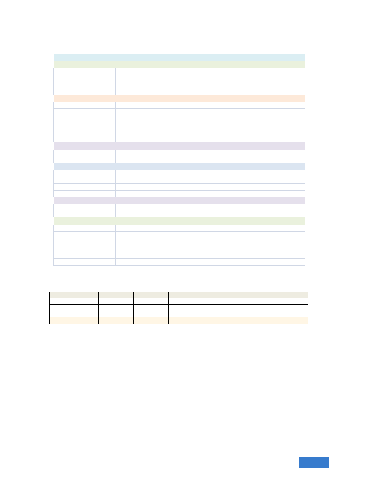
Feature Electrical / Mechanical specification
LEDs (Nav / Landing / Warning) -All ESD protected to 415 KV
Red LED 40 ~ 50 l umens typi cal l uminous flux (2θ/2 Vi ewing angle 140°)
Green LED 60 ~ 80 l umens typi cal l uminous flux (2θ/2 Vi ewing angle 135°)
White LED 120 ~ 130 l umens typi cal lumi nous flux (2θ/2 Viewing angle 115°)
LED outputs (Max current) 680mA per cha nnel (>1 Watt per cha nnel)
Electrical Interfaces - All ESD protected to 415 KV
T Connector (input V) Nominal ly min 5v to abs olute max 26.2v
Ext Supply (input V) Nominal ly min 5v to abs olute max 26.2v (Ma x 2A)
RC Rx input on / off (i nput V) Nominal ly min 5v to absolute max 7.5v as power input (input to ADC)
RC output, (output V) 5.2V (max 3A continuous, 4A bursts, then 5v) BEC function
RC output, (input V) Nominal ly min 5v to absolute max 26.2v a s power input
USB Mini USB V2.0 (absol ute max 6.5v)
Signal Interfaces
RC Rx input PWM (i nput) Nominal ly min 1 ms, max 2 ms, 15ms peri od (0v to a bsolute max 7.5v square wave)
RC output, (output) Nominal ly min 1 ms, max 2 ms, 15ms peri od (0v to 5.2v square wave)
LED indicators
Red : Battery Wa rning Fla shing: LiPo in danger zone, runni ng low. Continuous ly on: LiPo vol tage very l ow state!
Blue: System Operati onal Intermittent flas hing. System micro up and runni ng
Green: Mode indicati on Continuous: Super bri ght mode, Off: High bri ghtness mode
Yellow: Low bat detect mode More on than off : LowVolt mode, more off than on: LowTime mode, symmetric al on/off: Both modes
DIP Switches
DIP1 (4 switches) LowVBat mode cell count and LED bri ghtness mode
DIP2 (4 switches) LowVTime mode durati on programming a nd RC Rx input / RC Rx output i nvert
Operational and Conformance
IEC Designed to meet IEC 61000-4-2 level 415 kV (air dischar ge) 8 kV (contact dis charge)
MIL Designed to meet MIL STD 883G - Method 3015-7: clas s 3 Human body model
RoHS Compli ant
Temperature -30 °C to +85 °C
Protection PCB-A is sprayed with an a cryli c coating for protection agai nst fingerpri nts / grease
Fla shing s equence Meets FAA Doc. No. 5066, 29 FR 18291 (I ncl. Amdts. up to 25-41, 42 FR 36970, July 18, 1977)
9.0 Electrical Specifications
Cells 1 2 3 4 5 6
High Level (V)
4.2
8.4
12.6
16.8
21.0
25.2
Low level (V)
3.7
7.4
11.1
14.8
18.5
22.2
Very Low (V)
3.3
6.6
9.9
13.2
16.5
19.8
Trigger V (default)
3.4
6.8
10.2
13.6
17
20.4
Note1 : By default the trigger point for low battery level detect is 3.4V per cell. This to protect the LiPo battery. Trigger level value can be
changed with advanced command (see section 7.6.1 of this document)
Note2: Hysteresis at the trigger point value set to 1% by default. (Can change with advanced command)
Note3 : LiPo battery voltage measurement error, max ± 0.2%
Note : If using the BEC output function, cannot have only RC Rx input (5V) as input power source. Must have a power source of
minimum 6V, preferably higher. Only 3A for input voltages above 12v.
Page 21

Bluelight Technologies Co. Ltd. | BL-NavLV User Manual V1.0
21 of 21
10.0 Safety
10.1 LED Brightness
The LEDs are very bright (but still a Class 1 LED product). However please avoid direct close up and
prolonged eye contact. Also avoid viewing through optical instruments.
10.2 LED Temperature
The 1W LED Star PCB will get very hot during operation, especially the constantly on LEDs. With no airflow,
temperatures can reach up to 65 0C. Please take care. If possible please mount them onto some type of
metal material to aid in heat dissipation.
The in-line protection resistors will also get a little hot, but should not exceed 55 0C (Note, maximum finger
touch temperature in 65 0C). So please take care here also.
WARNING:
These LEDs are very bright, please avoid direct close-up /
prolonged eye contact
See http://www.bluelight-tech.com/BL-NavLV.htm for more information
Contact: [email protected]
All content copyright © 2014 Bluelight Technologies Co. Ltd.
199 / 206 Moo3, Soi Tha It, Rattanathibeth Road,
Muangnonthaburi, Nonthaburi 11000.
 Loading...