


SG210
Table of contents
 Loading...
Blue Coat® Systems
SG210 Series
Installation Guide
Version: SGOS 5.2.x

Contact Information
Blue Coat Systems Inc.
420 North Mary Ave
Sunnyvale, CA 94085-4121
http://www.bluecoat.com/support/contact.html
bcs.info@bluecoat.com
http://www.bluecoat.com
For concerns or feedback about the documentation: documentation@bluecoat.com
Note This equipment has been tested and found to comply with the limits for a Class A Digital device pursuant to Part 15 of the FCC
Rules. These limits are designed to provide reasonable protection against harmful interference when the equipment is operated in a
commercial environment. This equipment generates, uses, a nd can radiate radio frequency energy, and if not installed an d used in
accordance with the instruction manual, might cause harmful interference to radio communications. Operation of this equipment in
a residential area is likely to cause harmful interference in which case the users are requir ed to correct the interference at their own
expense.
Copyright© 1999-2008 Blue Coat Systems, Inc. All rights reserved worldwide. No part of this document may be reproduced by any
means nor modified, decompiled, disassembled, published or distribute d, in whole or in part, or translated to any electronic medium
or other means without the written consent of Blue Coat Systems, Inc. All right, title and interest in and to the Software and
documentation are and shall remain the exclusive property of Blue Coat Systems, Inc. and its licensors. ProxyA V™, CacheOS™,
SGOS™, SG™, Spyware Interceptor™, Scope™, RA Connector™, RA Manager™, Remote Access™ and MACH5™ are trademarks
of Blue Coat Systems, Inc. and CacheFlow®, Blue Coat®, Accelerating The Internet®, Prox ySG®, WinProxy®, AccessNow®, Ositis®,
Powering Internet Management®, The Ultimate Internet Sharing Solution®, Cerberian®, Permeo®, Permeo Tech nologies , Inc.®, and
the Cerberian and Permeo logos are registered trademarks of Blue Coat Systems, Inc. All other trademarks contained in this
document and in the Software are the property of their respective owners.
BLUE COAT SYSTEMS, INC. DISCLAIMS ALL WARRANTIES, CONDITIONS OR OTHER TERMS, EXPRESS OR IMPLIED,
STATUTORY OR OTHERWISE, ON SOFTWARE AND DOCUMENTATION FURNISHED HEREUNDER INCLUDING WITHOUT
LIMITATION THE WARRANTIES OF DESIGN, MERCHANTABILITY OR FITNESS FOR A PARTICULAR PURPOSE AND
NONINFRINGEMENT . IN NO EV ENT SHALL BLUE COAT SYSTEM S, INC., ITS SUPPLIERS OR ITS LICENSORS BE LIABLE FOR
ANY DAMAGES, WHETHER ARISING IN TORT, CONTRACT OR ANY OTHER LEGAL THEORY EVEN IF BLUE COAT
SYSTEMS, INC. HAS BEEN ADVISED OF THE POSSIBILITY OF SUCH DAMAGES.
Document Number: 231-02943
Document Revision: E.0 March 2009
Important: Follow all warnings and instructions marked on the product and included in this
manual.
Blue Coat SG210 Installation Guide

Contents
Chapter 1: The SG210 Series Appliance ................................................................................................5
Unpacking the SG210......................................................................................................................................... 5
Front and Back Panel Features .........................................................................................................................5
The Front-Panel LEDs................................................................. ... ................................. ............................ 5
Rear Components........................................................................................................................................ 6
Installing the SG210 ...........................................................................................................................................7
Placing the SG210 on a Shelf or Tabletop ................................................................................................7
Mounting the SG210 on a Wall .................................................................................................................7
Mounting the SG210 in an Equipment Rack ...........................................................................................9
Rack-Mounting Notes................................................................. ... ................................. ............................ 9
Powering on the SG210 ....................................................................................................................................10
Chapter 2: First-Time Configuration .....................................................................................................13
Section A: Using the Serial Console to Configure Initial Settings 15
Connecting the SG210 to a PC Using a Direct Serial Port....................................................... ............ 15
Initial Configuration Using a Direct Serial Port Connection.............................................................. 15
Section B: Configuring the SG210 Using the Serial Setup Console 18
Performing the Manual Setup Using the Serial Console .....................................................................18
Section C: Configuring the SG210 Using the Web Setup Wizard 23
Section D: Configuring the SG210 Using Director Registr ation 26
Section E: Logging in to the SG210 30
Logging in to the SG210 Management Console ........................................... .........................................30
Logging in to the SG210 CLI ....................................................................................................................31
Chapter 3: Troubleshooting.................................................................................................................. 33
A Network Link is Not Established............................................................................................................... 33
The Web Setup Wizard Is Not Accessible ............................. ... .................................. .................................. 34
The SG210 Does Not Power On ........................................................................................... .......................... 34
Cannot Access the Serial Console ..................................................................................................................35
Cannot Access the Management Console ....................................................................................................35
The System LED Indicates Unhealthy Status............................................................................................... 35
A Security Warning Appears for the Initial Configuration Web Page..................................................... 37
Resetting the SG210 to Its Factory Defaults .............................................. ....................................................38
The SG210 Appliance Certificate is No Longer Valid After the IP Address Changes ...........................38
The SG210 Does Not Come Back Up After Rebooting ...............................................................................38
The SG210 Cannot Connect to the Director ...................................................................................... ............39
Connection Request Rejected by the Director.............................................................................................. 39
iii

Blue Coat SG210 Installation Guide
Chapter 4: Next Steps ............................................................................................................................41
Appendix A: Removing the Pass-Through Card .................................................................................43
Appendix B: Specifications ................ .... ... ... ... .................................................... ... ... .... ... ... ..................47
Environmental and Electrical .........................................................................................................................47
Appendix C: Regulatory Statements................................................................................... ................. 49
Rack-Mounting Safety Instructions ...............................................................................................................49
Class A Digital Warning .................................................................................................................................49
EC Community EMC Warning ......................................................................................................................49
Canadian EC EMC Warning ...........................................................................................................................49
Australia/New Zealand EMC Warning....................................................................................................... 50
Taiwan BSMI Notification ..............................................................................................................................50
Japan VCCI EMC Notification ...................................................... .................................. ............................... 50
China CCC Notification.................................................................................................................................. 50
Battery Warning Notification......................................................................................................................... 50
Declaration of Conformity................................... .................................. ......................................................... 52
Index ................................ ... ... .... ... .................................................... ... ... ... .... ...........................................53
iv
Chapter 1:The SG210 Series Appliance
This Installation Guide provides general instructions for installing, configuring, and using the SG210.
This chapter explains how to unpack the SG210, install it on the wall or in an equipment rack, and make all
necessary connections.
Unpacking the SG210
The SG210 is shipped fully assembled. When you receive and unpack the unit, verify that th e pa ckage
contains the following items:
❐ SG210 Series appliance ❐ License and warranty
❐ Serial cable ❐ Crossover adapter
❐ AC Power supply adapter ❐ AC power cord
❐ Skid-proof rubber pads (4) ❐ Wall mount bracket and screws
❐ Rack-mounting ear brackets (2)
and screws (6)
❐ Packet —Safety/Conformity ❐ Quick Start Guide
❐ Jumper (for pass-through card removal only—see Appendix
A:Removing the Pass-Through Card on page 43 for information)
Important: This product is intended for operation and servicing only by appropriately trained
technical personnel.
Dieses Produkt wird für Betrieb vorgehabt und wird nur durch passend ausgebildeten
technisches Personal gewartet.
Front and Back Panel Features
This section describes the front and back panel on the SG210.
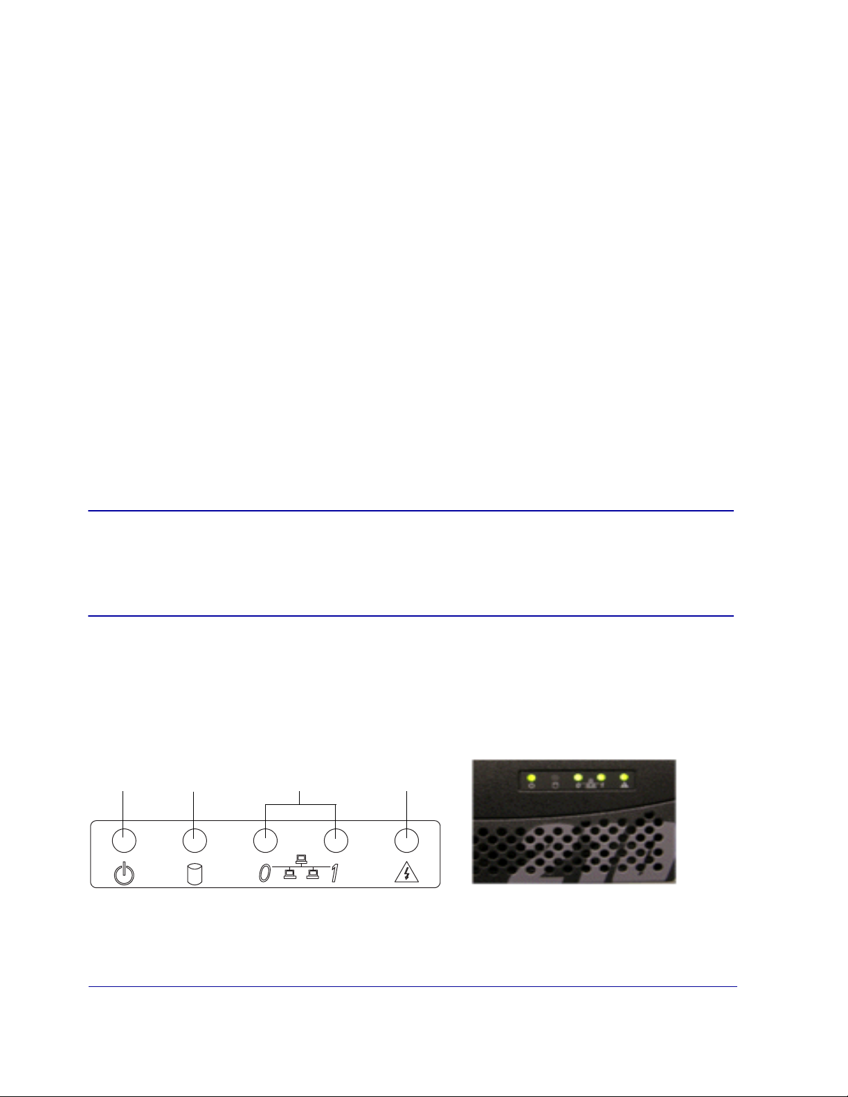
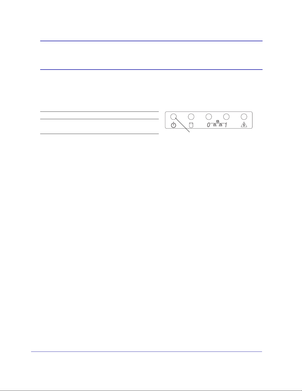
The Front-Panel LEDs
Power
Figure 1-1: Front-Panel LEDs
Disk Drive
Adapter Port
System
Chapter 1: The SG210 Series Appliance 5
Power LED
• No color: The SG210 is powered off or non-functional.
• Solid Amber: The SG210 is powered on but unable to perform tasks (such as while it boots up).
• Flashing Green to Amber: The SG210 is powered on but is not configured.
• Green: The SG210 is powered on and at least minimally configured.
Disk Drive LED
• Off: No disk activity.
• Green: The disk drive is being accessed (can also indicate compact-flash drive access).
Adapter Port LEDs (Network Adapter Ports 0 and 1)
• Off: No link
• Green: Link
• Flashing Green to Amber: Link and network activity
System
• Off: Nothing to report (SG210 is not powered on).
• Green: SG210 is healthy.
• Amber: SG210 is unhealthy, inspect the appliance and perform a maintenance check before it becomes
critical.
• Flashing Green to Amber: Indicates a critical system warning—the SG210 requires immediate
attention. See “The System LED Indicates Unhealthy Status” on page 35 for information about locating
the source of an unhealthy System LED reading.
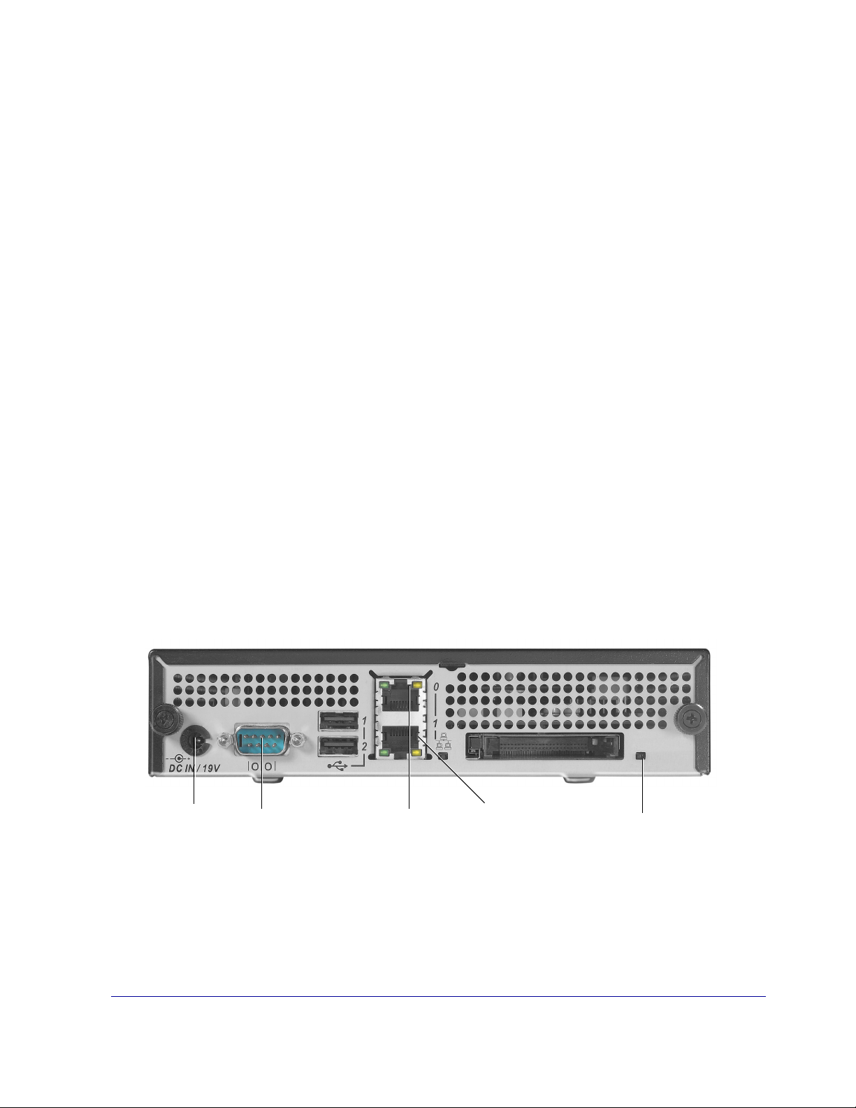
Rear Components
Power Supply
Adapter Port
Figure 1-2: Components on the Back of the SG210
Power Supply Adapter Port
Serial
Port
Ethernet Port 0 or
designated WAN port
Ethernet Port 1 or
designated LAN port
Reset button
Connects to the power supply adapter. Connecting a power cable to the power supply adapter and to an
electrical outlet powers on the SG210.
6 Blue Coat SG210 Installation Guide

Serial Port
Connects to a PC, serial terminal, or standalone serial console box. Use this port to configure or maintain
the SG210 using the command line interface (CLI).
Ethernet Adapter Ports 0 and 1
Two full-duplex, auto-sensing Ethernet network adapters supporting 10/100 Base-T connections. The
physical interfaces of a bridge card are designated as WAN or LAN interfaces to help administrators
configure the bridge. For example, a two-port bridge card has the following interfaces:
Interface 0 (WAN)
Interface 1 (LAN)
If you have a MACH5 license, a programmable bridge card, and labeled WAN/LAN interfaces, the WAN
interface allows transparent interception by default. All other cases, all traffic is bypassed by default.
Reset Button
Restores the appliance to its factory defaults. All configurations are lost when you reset the appliance.
Installing the SG210
There are three methods of installing the SG210 appliance—placing it on a shelf or tabletop, mounting it
on a wall, or mounting it in an equipment rack.
Important: The SG210 ships with a pass-through card that is designed to fail open when the
appliance is powered down or loses po wer so tha t Web traffic remains uninterrupted. If
you prefer that the appliance fa il clos ed, remov e the pass-though car d bef or e mounting
the SG210 on a rack. See Appendix A:Removing the Pass-Through Card on page 43.
Placing the SG210 on a Shelf or Tabletop
For shelf or tabletop use, affix the four skid-proof rubber pads to the underside of the SG210.
Mounting the SG210 on a Wall
To mount the SG2 10 vert ically on a wall, use the wall-mounting bracket, anchors, and screws; you also
need a drill and a Phillips screwdriver.
1 Use the holes on the wall-mounting bracket to mark th e positions on the wall for the two anchors; drill
holes in the wall just large enough to fit each anchor.
Chapter 1: The SG210 Series Appliance 7
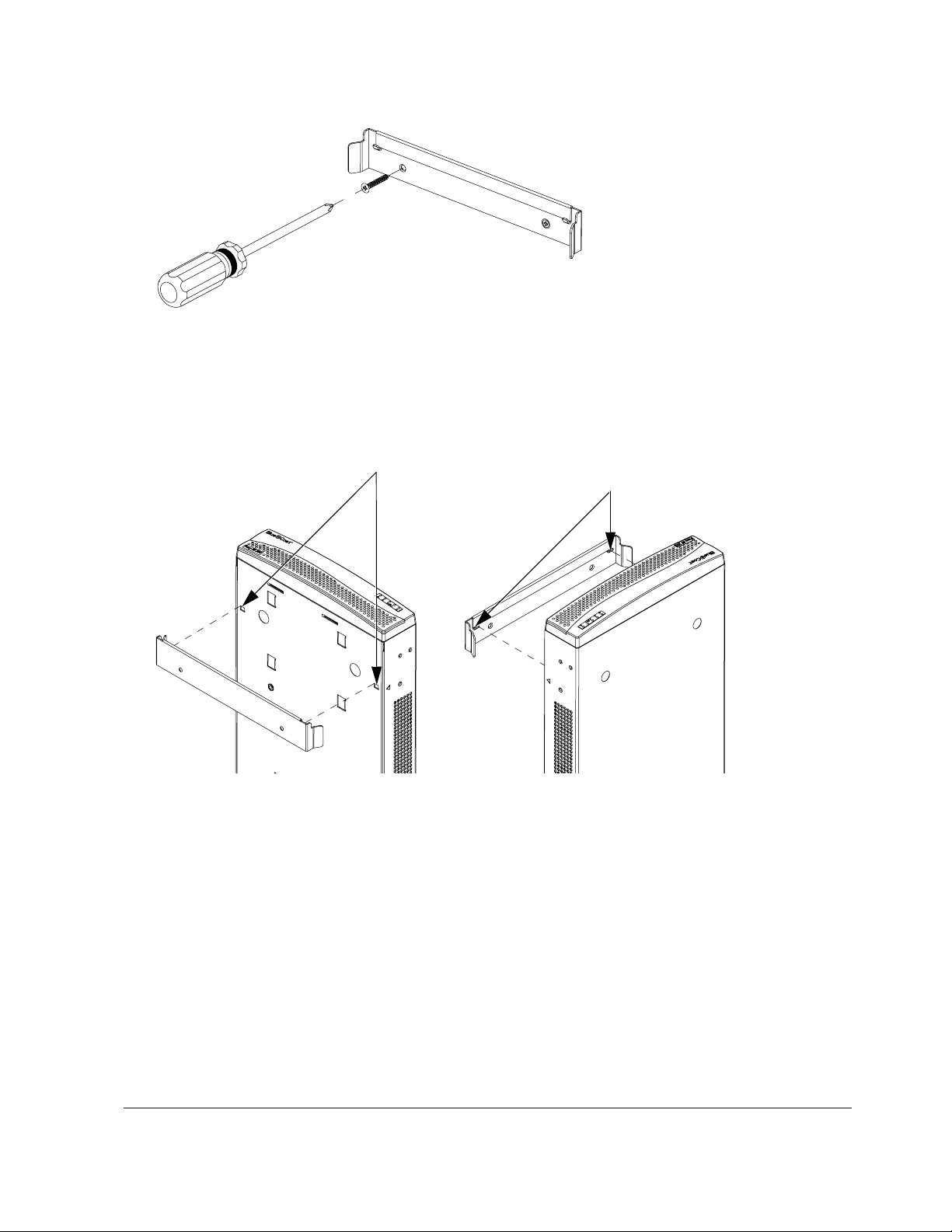
2 Line up the hole s on th e wall- mounting bracke t with the anchors . Use a Phil lips s crewdriver to secure
the bracket to the wall using the wall-mount screws.
Figure 1-3: Secure the Wall-Mount Bracket to the Wall
3 Locate the two notches on the bottom front of the chassis of the SG210; an arrow on each side of the
SG210 points to each notch.
4 Mount the SG210 on the wall-mount bracket by inserting the notches on the SG210 into the hooks on
the bracket and pushing down slightly to lock the appliance into place.
3 Locate the two notches
Figure 1-4: Secure the Wall-Mount Bracket to the Wall
4 Insert the two notches
into the wall hooks
8 Blue Coat SG210 Installation Guide
Mounting the SG210 in an Equipment Rack
This section includes the safety conventions and the instructions for mounting the SG210 on an equipment
rack.
Rack-Mounting Notes
Read these notes before rack-mounting the SG210.
A Elevated Operating Ambient—If installed in a closed or multi-unit rack assembly, the operating
ambient temperature of the rack environment may be greater th an room ambient. Therefore,
consideration should be given to installing the equipment in an environment compatible with the
maximum ambient temperature (Tmax) specified by the manufacturer.
B Reduced Air Flow—Installation of the equipment in a rack should be such that the amount of air flow
required for safe operation of the equipment is not compromised.
C Mechanical Loading—Mounting of the equipment in the rack should be such that a hazardous
condition is not achieved due to uneven mechanical loading.
D Circuit Overloading—Consideration should be given to the connection of the equipment to the supply
circuit and the effect that overloading of the cir cui ts might have on over current protection and supply
wiring. Appropriate consideration of equipment nameplate ratings should be used when addressing
this concern.
E Reliable Earthing —Reliable earthing of rack-mounted equipment should be maintained. Particular
attention should be given to supply connections other than direct connections to the branch circuit (for
example, use of power strips).
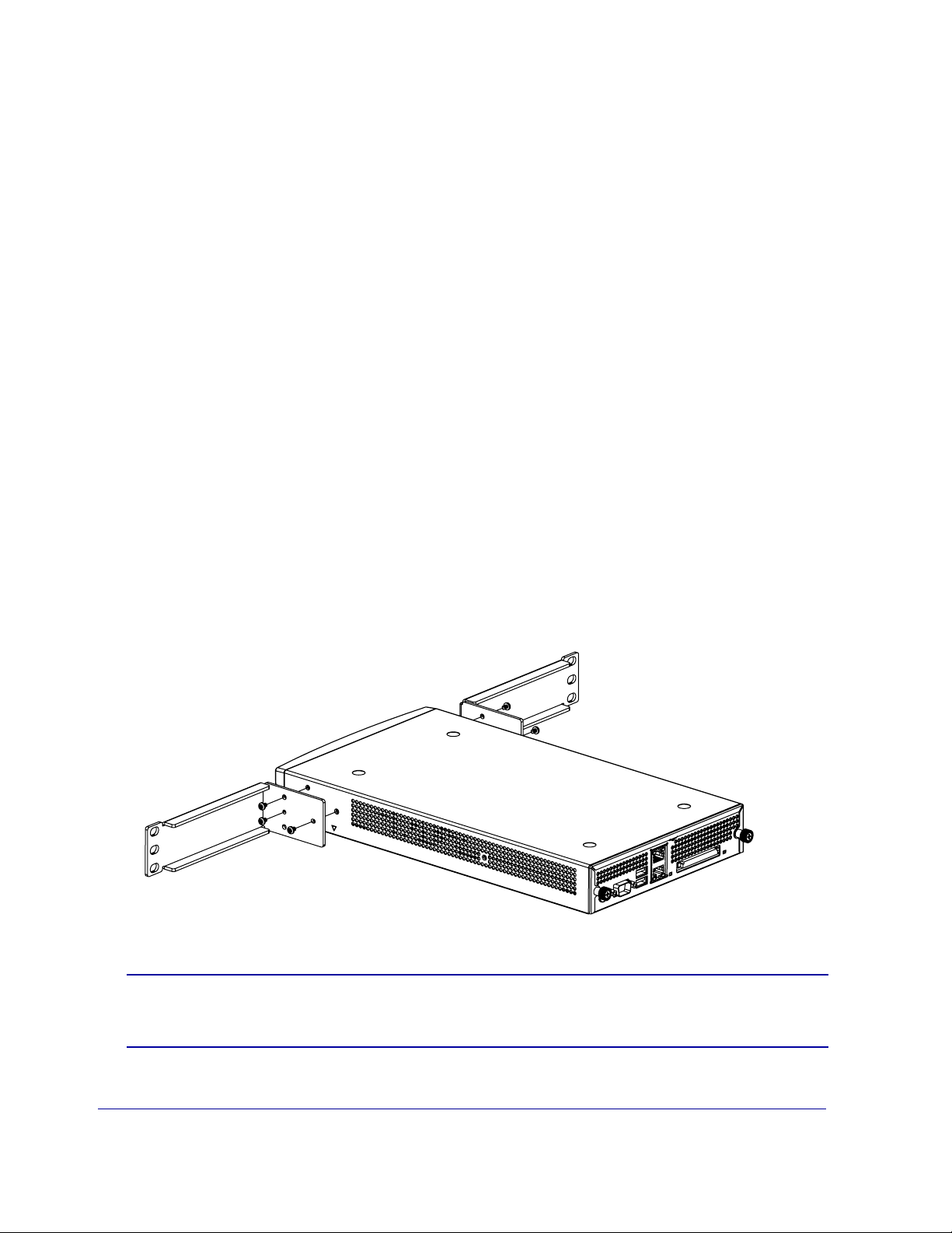
To mount the SG210 horizontally into an equipment rack, use the rack-mounting brackets and screws; you
also need a Phillips screwdriver.
1 Use a Phillips screwdriver to attach the brackets to the SG210; use three screws on each side, as shown
in Figure 1-5.
Figure 1-5: Attach the Brackets to the SG210
Important: Ensure that the SG210 is fully supported when mounting it in the equipment rack:
do not allow the brackets to support the SG210 until they are securely placed.
Chapter 1: The SG210 Series Appliance 9
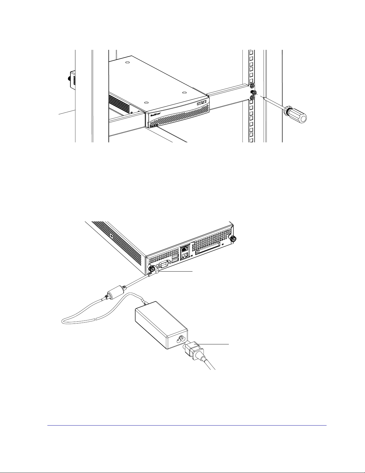
2 While fully supporting the weight of the SG210, mount the brackets onto the equipment rack using
three equipment rack screws on each side (use the screws provided by the rack manufacturer).
Figure 1-6: Secure the SG210 to the Equipment Rack
Powering on the SG210
Power on the SG210 by plugging in the power supply adapter and power cable.
1 Plug the power supply adapter into the SG210, ensuring that the barrel of the power supply adapter is
fully inserted into the SG210.
2 Plug one end o f th e power cable into the power supply adapter.
Plug the power supply
adapter into the SG210
Figure 1-7: Plug in the Power Adapter and Power Cable
Plug the power
cable into the power
supply adapter
10 Blue Coat SG210 Installation Guide
3 Plug the other end of the power cable into a power outlet.
Important: The use of a wall-socket adapter is not recommended, Blue Coat recommends
getting a localized power cable for your appliance. Country-specifi c power cables
are required to maintain product safety compliance and the warranty.
The SG210 powers on and the operating system boots up. While the SG210 is booting up
(approximately one minute), the Power LED on the fr ont panel (the left-most LED) glows solid amber.
4 After the SG210 boots up, verify that the Power LED behaves as described below:
Configuration Status Power LED Activity
Not completed Flashing green and amber
Completed Solid green
If the Power LED is solid green after booting up, an initial configuration has already been performed.
If you did not perform an initial configuration, restore the appliance to its factory defaults to restart
the initial configuration (see “Resetting the SG210 to Its Factory Defaults” on page 38).
Power LED
Chapter 1: The SG210 Series Appliance 11

12 Blue Coat SG210 Installation Guide

Chapter 2:First-Time Configuration
First-time configuration involves setting the basic network parameters and ensuring that the SG210 and
software are working properly.
The initial configuration might be done either using a st andalone P C, a seri al terminal, or after pl acing th e
SG210 into your network. The placement of the SG210 depends on the flow of traffic within your
organization. The SG210 must be able to intercept initial packets on each client or application connection
to be optimized. Typical deployments include:
❐ Explicit proxy configuration— where the client browser is explicitly configured to use a proxy
server. The browser is given the IP address and port number of the SG210.
It is also possible to configure the br owser to download the pr oxy settings fr om a Web server. This
is called a Proxy Auto-Configuration (PAC) file.
❐ T rans parent pr oxy — wher e the client br owser does not know that the traffic is being proces sed by
a machine other than the Origin Content Server. To enable the SG210 to intercept traffic sent to it,
you must create a service and define it as transparent. The service is configured to intercept traffic
for a specified port, or for all IP addresses on that port. Traffic redirection is managed through
policies you create on the redirection device.
A transparent HTTP proxy, for example, typically intercepts all traffic on port 80 (all IP addr esses).
To make sure that the appropriate traffic is directed to the ProxySG, deploy hardware such as a
Layer-4 switch or a WCCP router, or the ProxySG appliance’s softwa re bridge that can redirect
selected traffic to the appliance.
Note: The cabling and connections specific to the deployment of the SG210 are not within the
scope of this book. Check with your network administrator for guidance on deploying the
SG210 within your organization.
You must use the serial console to assign the IP address and the IP subnet mask for the SG210 appliance.
Choose one of the following methods to configure the SG210:
• Serial Setup Console
Use this method if you want to configure basic settings only and do not immediately require traffic
interception of specific services. If you want to configure traffic interception or ADN settings, choose
the Web Setup Wizard option. See Section A: “Using the Serial Console to Configure Initial Settings on
page 15 to configure initial settings. To continue with the configuration using the serial console setup
see Section B: “Configuring the SG210 Using the Serial Setup Console on page 18.
• Web Setup Wizard
Use the Web Setup Wizard if you need to immediately configure traffic interception or ADN settings.
To use the Web Setup W izar d, you must first configure an IP address for the appliance using the serial
console. See Section A: “Using the Serial Console to Configure Initial Settings on page 15 to configure
initial settings. To continue with the configuration using the Web setup wizard see Section C:
“Configuring the SG210 Using the Web Setup Wizard on page 23.
Chapter 2: First-Time Configuration 13

• Director Registration
Use this method only if you have a Blue Coat 510 Director. The Director allows you to configure an SG
appliance and automatically register it with the Director. See Section A: “Using the Serial Console to
Configure Initial Settings on page 15 to configure initial settings. To continue with the configuration
using the Web setup wizard see Section D: “Configuring the SG210 Using Director Registration on page
26.
After first-time configuration is comple te, log on to the SG210 and us e the command-line i nterface (CLI) or
Management Console to fully configure the system. See Section E: “Logging in to the SG210 on page 30 and
refer to the Blue Coat ProxySG Configuration and Management Guide Suite for information on how to fully
configure the software. Download this manual from the Blue Coat WebPower site at:
https://www.bluecoat.com/support/manuals
Note: You must have a WebPower account to access the documentation.
14 Blue Coat SG210 Installation Guide
Section A: Using the Serial Console to Configure Initial Settings
This section describes how to configure the SG210 using a direct serial port connecti on u si n g a standalone
serial terminal or a PC to perform a first-time configuration of the following basic network information:
• IP address • IP subnet mask
• IP gateway address • DNS server
This procedure is valid for all SG210 Series appliances.
PC Note: If the PC is using standard serial port settings, you should have a problem-free
connection. If your PC has non-standard serial port settings, refer to your PC.
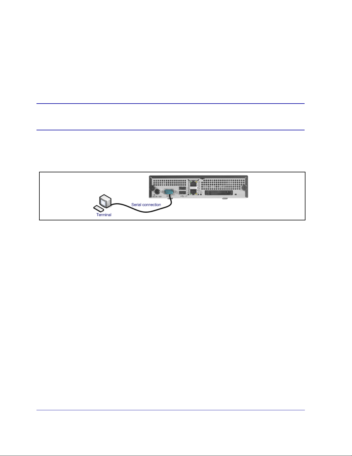
Connecting the SG210 to a PC Using a Direct Serial Port
Use the image below to configure the SG210 to a PC for direct serial port access:
Complete the procedure by r eading onscreen material and entering data where nec essary. In the procedure
below, entries in bold text are ones for which you are required to enter data.
Initial Configuration Using a Direct Serial Port Connection
1
Power on and connect the serial terminal or PC as described below (the SG210 must be powered off):
Serial terminal: Connect the terminal’s serial cable to the SG210’s serial console port; start the terminal
and verify that it is set using the parameters described below.
PC: Connect a serial cable to a serial port on the PC and to the SG210’s serial console port; start the PC,
open a terminal emulator (such as HyperTerminal), and connect to the serial port to which you
attached the cable. Create and name a new connection (either a COM or TCP/IP), and verify that the
port is set using the parameters described below.
• Baud rate: 9600 bps • Data bits: 8
• Parity: none • Stop bits: 1
• Flow control: none • Smooth-scroll: disabled
• Emulation: VT 100
Chapter 2: First-Time Configuration 15

2 Power on the SG210 and wait for the system to finish booting.
The following configuration alert displays:
******************* CONFIGURATION ALERT *******************
System startup cannot continue for one of these reasons:
(a) Need at least one adapter configured with an
IP address and subnet.
(b) Need the console password and enable password.
(c) Need to specify the trial edition.
********** SYSTEM STARTUP TEMPORARILY SUSPENDED **********
Press "enter" three times to activate the serial console
Figure 2-8: Initial Setup—Configuration Alert
3 Press <Enter> three times. When the Welcome to the ProxySG Appliance Setup Console prompt
appears, the system is ready for the first-time network configuration.
Welcome to the SG Appliance Setup Console
How do you want to set up the SG appliance?
M)anual setup using the serial console
W)eb wizard (after setting network configuration using the serial
console)
R)egister with Director (registration password required)
Choose setup mode:
Figure 2-9: Initial Setup—SG Appliance Setup Console
4 You can do one of the following:
❐ Type M to use the Manual Serial Setup Console. This option allows you to continue using the serial
console for fully configuring your SG210 appliance.
❐ Type W to use the Web Setup Wizard. This option requires you to assign the IP address, IP subnet
mask, and the IP gateway through the serial console, then you can continue the configuration
using the Web browser.
❐ Type R to use Director Registration.This option requires you to assign the IP address, IP subnet
mask, and the IP gateway for the SG210 and the IP address for the Director through the serial
console, before registering the SG210 with a Director.
Note: If you have removed the pass-through card, you are asked if you want to configure a
software bridge. If you enter YES, you must configure at least one bridge port and
associate a network interfac e with it.
16 Blue Coat SG210 Installation Guide

5 If you select M, the following screen displays:
Welcome to the ProxySG Appliance Setup Console
---------------------- (page 1 of 5) ---------------------
Press <ESC> at any time to return to the main menu
Setup mode: Manual
DIRECTIONS:
Please enter the IP addresses for the SG Appliance.
The following interface will be configured:
1. Bridge passthru-0 (WAN link, LAN link)
IP address [0.0.0.0]: 10.0.1.246
IP subnet mask [255.255.255.0]:
IP gateway [0.0.0.0]: 10.0.1.1
DNS server [0.0.0.0]: 10.0.0.100
You have entered the following IP addresses:
IP address: 10.0.1.246
IP subnet mask: 255.255.255.0
IP gateway: 10.0.1.1
DNS server: 10.0.0.100
Would you like to change any of them? Y/N [No]
Figure 2-10: Initial Setup—Page One
Note: A similar screen displays for each of the configuration options. The parameters that you
enter vary accordi ng to the selected configuration option.
6 To continue using the serial setup console, see Section B: “Configuring the SG210 Using the Serial Setup
Console on page 18.
For details on the Web Setup Wizard, see Section C: “Configuring the SG210 Using the Web Setup
Wizard on page 23.
To use the Director Registration fea ture, see Section D: “Configuring the SG210 Using Director
Registration on page 26.
Chapter 2: First-Time Configuration 17
Loading...