

Page 1

BCT-ETX-EVAL-BP
ETX Format Evaluation Backplane
User Manual
Document Reference BCT-ETX-EVAL-BP User Manual
Document Issue Level 1.0
Manual covers PCBs with the following Issue 1.x (where 'x' is any alphanumeric).
Blue Chip Technology Ltd.
Chowley Oak
Tattenhall
Chester
CH3 9EX
U.K.
Telephone: +44 (0)1829 772000
Facsimile: +44 (0)1829 772001
www.bluechiptechnology.co.uk
Page 2

BCT-ETX-EVAL-BP BACKPLANE CONTENTS
CONTENTS
CONTENTS ................................................................................................................ 2
INTRODUCTION ........................................................................................................ 4
COMPANY PROFILE .....................................................................................................................4
COPYRIGHT .................................................................................................................................4
LIMITATIONS OF LIABILITY ..........................................................................................................4
RELATED PUBLICATIONS ............................................................................................................5
TRADEMARKS ..............................................................................................................................5
OVERVIEW ...................................................................................................................................6
PRECAUTIONS .............................................................................................................................6
Electro-Static Discharges .......................................................................................................................6
On-Board Battery ...................................................................................................................................6
BIOS & CMOS RAM...............................................................................................................................7
Electromagnetic Compatibility ................................................................................................................7
Mounting the ETX processor board .........................................................................................................8
USER GUIDE .............................................................................................................. 9
MANUAL ORGANISATION ............................................................................................................9
LAYOUT ...................................................................................................................................... 10
CONFIGURATION JUMPERS ..................................................................................................... 12
Switched VEE polarity selection ............................................................................................................. 12
LCD Voltage Selection .......................................................................................................................... 12
Parallel port / floppy disk drive shared interface ................................................................................... 12
2½" hard disk mode select .................................................................................................................... 12
Resume Reset Input ............................................................................................................................... 13
Drive configuration for secondary IDE ribbon cable connector ............................................................. 13
Drive configuration for secondary 32pin ATA-Disk Chip Connector ...................................................... 13
ATA-Disk Chip Read / Write Control..................................................................................................... 13
CMOS Control ...................................................................................................................................... 13
PCI VIO Control ................................................................................................................................... 14
COM1 RS485 Duplex Control ............................................................................................................... 14
COM1 Protocol Control ....................................................................................................................... 14
COM1 Half Duplex Control Signal Select ............................................................................................. 14
5V Standby Voltage Select..................................................................................................................... 14
ATX Power Supply Bypass .................................................................................................................... 15
CONNECTORS ........................................................................................................................... 16
CD Audio Input .................................................................................................................................... 16
Audio Input / Output Jacks .................................................................................................................... 16
USB Ports 3 and 4 ................................................................................................................................ 16
Ethernet and USB ................................................................................................................................. 17
VEE Voltage Control ............................................................................................................................. 17
VEE Voltage Output .............................................................................................................................. 17
LCD TTL Output................................................................................................................................... 18
LVDS Output ........................................................................................................................................ 19
System Management Bus ....................................................................................................................... 19
I2C Bus ................................................................................................................................................. 20
50 way Primary IDE Connector ............................................................................................................ 20
40 way Primary IDE Connector ............................................................................................................ 20
Blue Chip Technology Limited Page 2
Page 3

BCT-ETX-EVAL-BP BACKPLANE CONTENTS
Keyboard Inhibit ................................................................................................................................... 21
40 way Secondary IDE Connector ......................................................................................................... 21
Battery low ........................................................................................................................................... 21
Utilities ................................................................................................................................................ 21
Parallel Port 2 ...................................................................................................................................... 22
Serial Port 3 ......................................................................................................................................... 22
Secondary Floppy Disk Interface .......................................................................................................... 22
Serial Port 4 ......................................................................................................................................... 22
Serial Port 1 (RS232) and Serial Port 2................................................................................................. 22
IRDA..................................................................................................................................................... 23
Serial Port 1 (RS485) ............................................................................................................................ 23
ATX Power ........................................................................................................................................... 23
Parallel Port 1 / VGA ........................................................................................................................... 23
Primary Floppy Disk Interface .............................................................................................................. 24
PS/2 Mouse and Keyboard .................................................................................................................... 24
Composite / S-Video Output .................................................................................................................. 24
STANDARD CONNECTORS .................................................................................... 25
AMENDMENT HISTORY .......................................................................................... 26
Blue Chip Technology Limited Page 3
Page 4

BCT-ETX-EVAL-BP BACKPLANE INTRODUCTION
INTRODUCTION
COMPANY PROFILE
Blue Chip Technology is a leading specialist PC product manufacturer in Europe, providing innovation with
quality design and manufacturing from a single source.
Based in the North West of England, our purpose built complex contains both advanced research and
development facilities, and manufacturing facilities.
Specialising in the provision of industrial computing and electronic solutions for a wide range of UK and
European organisations, Blue Chip Technology has one of the UK's largest portfolios of industrial PCs, Single
Board Computers, peripherals and data acquisition cards. This extensive range of products, coupled with our
experience and expertise, enables Blue Chip Technology to offer an industrial processing solution for any
application. This is one of the products from our portfolio, providing you with a cost effective product
development and volume production tool.
A unique customisation and specialised system integration service is also available, delivering innovative
solutions to customers problems. The company's success and reputation in this area has led to a number of
large design and manufacturing projects for major companies.
British Standards Institute approval (BS EN 9001) means that all of Blue Chip Technology's design and
manufacturing procedures are strictly controlled, ensuring the highest levels of quality, reliability and
performance.
Blue Chip Technology are committed to the single European market, and continue to invest in the latest
technology and skills to provide high performance computer and electronic solutions for a world-wide
customer base.
COPYRIGHT
All rights reserved. No part of this publication may be reproduced, stored in any retrieval system, or
transmitted, in any form or by any means, electronic, mechanical, photocopied, recorded or otherwise, without
the prior permission, in writing, from the publisher. For permission in the UK please contact Blue Chip
Technology.
Information offered in this manual is believed to be correct at the time of printing. Blue Chip Technology
accepts no responsibility for any inaccuracies. The information contained herein is subject to change without
notice. There are no express or implied licences granted herein to any intellectual property rights of Blue Chip
Technology Ltd.
LIMITATIONS OF LIABILITY
In no event shall Blue Chip Technology be held liable for any loss, expenses or damages of any kind
whatsoever, whether direct, indirect, incidental or consequential, arising from the design or use of this product
or the support materials supplied with this product. If this product proves to be defective, Blue Chip
Technology is only obliged to replace or refund the purchase price at Blue Chip Technology's discretion
according to their Terms and Conditions of Sale.
Blue Chip Technology Limited Page 4
Page 5

BCT-ETX-EVAL-BP BACKPLANE INTRODUCTION
RELATED PUBLICATIONS
The following publications will provide useful information related to the Standard Personal Computer and can
be used in conjunction with this manual.
• IBM Personal Computer AT Technical Reference, 1502494, IBM, 1984.
• IBM Personal System/2 and Personal Computer BIOS Interface Technical Reference, 15F0306, IBM,
1987.
• The Programmers PC Sourcebook, Microsoft
• The Winn L. Rosch Hardware Bible, Brady
• BCT-ETX-C3-XXX User Manual
TRADEMARKS
All trademarks and registered names acknowledged.
IBM, PC, AT and PS/2 are trademarks of International Business Machines Corporation (IBM).
Phoenix BIOS is a trademark of Phoenix Technologies Inc
Intel is a registered trademark of the Intel Corporation.
All 80x86 and Pentium processors are registered trademarks of Intel Corporation.
MS-DOS and WINDOWS are registered trademarks of the Microsoft Corporation.
Linux is a registered trademark of Linus Torvalds.
ATA-Disk Chip is a trademark of Silicon Storage Technology Inc.
Blue Chip Technology Limited Page 5
Page 6

BCT-ETX-EVAL-BP BACKPLANE INTRODUCTION
OVERVIEW
The ETX concept provides the user with a plug in processor board with a standard connector interface, with
fixed connector locations and predefined IO functions. This allows the user to concentrate their design efforts
on the supporting baseboard for the target application. This modular approach provides a cost effective means
of system upgrade and allows the user to easily validate a number of CPU board price / power / performance
options.
Blue Chip Technology provides a number of ETX processor board modules as part of the BCT-ETX-C3-XXX
family. These processor boards are available with CPU build options of an extremely Low Power VIA Eden
ESP 4000 (400MHz) and Low Power VIA C3 1Gz processor. The 400MHz ESP C3 version of BCT-ETXC3-XXX is targeted at lower cost, power conscious, and performance driven applications. The 1Ghz C3 build
offers a higher performance solution for applications where reduced power is less of a requirement. In addition
a special 266MHz version is available for the lowest power consumption applications. Further variants are
VIA Eden 733Mhz and VIA C3 800Mhz processors.
The BCT-ETX-EVAL-BP backplane provides access to all of the features of the BCT-ETX-C3-XXX
processor board through industry standard connectors utilising the ATX form factor. This arrangement allows
the processor board to be tested and evaluated whilst the target baseboard is being developed. As the BCTETX-EVAL-BP backplane provides expansion through standard interfaces such as PCI and ISA it allows
external peripherals devices to be tested to ensure that the correct silicon choices are made for the target
baseboard.
PRECAUTIONS
Certain precautions are necessary when designing with, handling, and using circuit boards. It is imperative
that precautions are taken at all stages to avoid electro-static discharges, which will damage boards. Those
boards fitted with an on-board lithium battery must be handled carefully to avoid maltreatment of the
battery that could create a hazard.
ELECTRO-STATIC DISCHARGES
The devices on this card can be totally destroyed by static electricity. Also bear in mind that the damage
caused by static electricity may be partial and not immediately obvious. This could have an effect on your
product's reliability and warranty. Ensure that you take necessary static precautions, ideally you should
wear an approved wrist strap or if that is not possible, touch a suitable ground to discharge any static build
up. This should be repeated if the handling is for any length of time.
When carrying the board around, please place it into the anti-static bag in which it came. This will prevent
any static electricity build up. Do not use black anti-static bags because these tend to be conductive and will
discharge any on-board battery.
ON-BOARD BATTERY
The BCT-ETX-EVAL-BP backplane has an on-board lithium cell. The following precautions apply and
should be observed. If the battery is mistreated in any way there is a very real possibility of fire, explosion,
and harm. Great care should be taken with this type of battery. Under NO circumstances should it be:
• short-circuited
• exposed to temperatures in excess of 100 ºC or burnt
• immersed in water
Blue Chip Technology Limited Page 6
Page 7

BCT-ETX-EVAL-BP BACKPLANE INTRODUCTION
• unsoldered
• recharged
• disassembled
Expired batteries remain hazardous and must be disposed of in a safe manner.
BIOS & CMOS RAM
Please be aware that on single board computer products, it is possible to create configurations within the
CMOS RAM that make booting impossible. If this should happen, clear the CMOS settings, (see the
description of the Jumper Settings for details).
ELECTROMAGNETIC COMPATIBILITY
This product meets the requirements of the European EMC Directive (89/336/EEC) and is eligible to bear
the CE mark.
It has been assessed operating in a Blue Chip Technology housing. However, because the board can be
installed in a wide variety of chassis, certain conditions have to be applied to ensure that the compatibility is
maintained. Subject to those conditions, it meets the requirements for an industrial environment (ITE Class
A product).
• The board must be installed in a computer system chassis that provides screening suitable for an
industrial environment.
• Any recommendations made by the computer system manufacturer/supplier must be complied with
regarding earthing and the installation of boards.
• Any metal back plate must be securely screwed to the chassis of the computer to ensure good metal-to-
metal (i.e. earth) contact.
• Connector bodies must be securely connected to the enclosure.
• The external cabling to boards causes most EMC problems. It is imperative that any external cabling to
the board is totally screened, and that the screen of the cable connects to the metal end bracket of the
board or the enclosure and hence to earth. It is recommended that round, screened cables with a braided
wire screen are used in preference to those with a foil screen and drain wire. Use metal connector shells
that connect around the full circumference of the cable screen: they are far superior to those that earth
the screen by a simple “pig-tail”.
• The keyboard and mouse will play an important part in the compatibility of the processor card since they
are ports into the board. Similarly, they will affect the compatibility of the complete system. Fully
compatible peripherals must be used otherwise the complete system could be degraded. They may
radiate or behave as if keys/buttons are pressed when subject to interference. Under these circumstances
it may be beneficial to add a ferrite clamp on the leads as close as possible to the connector. A suitable
type is the Chomerics type H8FE-1004-AS.
• USB cables should be high quality screened types.
• Ensure that the screens of any external cables are bonded to a good RF earth at the remote end of the
cable.
Failure to observe these recommendations may invalidate the EMC compliance.
Warning
This is a Class A product. In a domestic environment this product may cause radio
interference in which case the user may be required to take adequate measures.
Blue Chip Technology Limited Page 7
Page 8

BCT-ETX-EVAL-BP BACKPLANE INTRODUCTION
MOUNTING THE ETX PROCESSOR BOARD
The BCT-ETX-EVAL-BP backplane has 4 mounting holes of 2.5mm diameter, which correspond to the
mounting holes on the BCT-ETX-C3-XXX processor board. Care should be taken on the underside of the
board to not cause any mechanical damage to the components adjacent to the mounting holes.
All connections to the BCT-ETX-EVAL-BP backplane are made through connectors X1-X4 inclusive.
These Hirose socket connectors (Part Number FX8-100S-SV) mate with corresponding Hirose plug
connectors (Part Number FX8-100P-SV) on the BCT-ETX-C3-XXX processor board.
When installing or removing the BCT-ETX-C3-XXX module into the target base board, ensure all power
has been removed. This includes the 5volt supply, the 5V stand-by supply and the external Lithium cell or
RTC back-up battery. Before applying power to the backplane and processor board ensure that all four
connectors have located and been pressed together firmly.
Blue Chip Technology Limited Page 8
Page 9

BCT-ETX-EVAL-BP BACKPLANE USER GUIDE
USER GUIDE
MANUAL ORGANISATION
This manual describes in detail the Blue Chip Technology BCT-ETX-EVAL-BP backplane used as a
companion to the BCT-ETX-C3-XXX family of single board computers.
We have tried to include as much information as possible but we have not duplicated information that is
provided in the standard IBM Technical References, unless it proved to be necessary to aid in the
understanding of either the BCT-ETX-C3-XXX single board computer or BCT-ETX-EVAL-BP backplane.
The manual is sectioned as follows:
Overview, listing the board's features and specification;
Layout, showing where the various items are located;
Installation, and associated issues;
Configuration jumpers;
Connector Pin-Out details.
We strongly recommend that you study this manual carefully before attempting to interface with BCT-ETXC3-XXX or change the standard configurations. Whilst all the necessary information is available in this
manual we would recommend that unless you are confident, you contact your supplier for guidance. IT IS
PARTICULARLY IMPORTANT THAT YOU READ THE SECTION 'PRECAUTIONS' BEFORE
HANDLING THE BOARD.
If you have any suggestions or find any errors concerning this manual and want to inform us of these, please
contact our Technical Services department with the relevant details.
Blue Chip Technology Limited Page 9
Page 10
BCT-ETX-EVAL-BP BACKPLANE LAYOUT
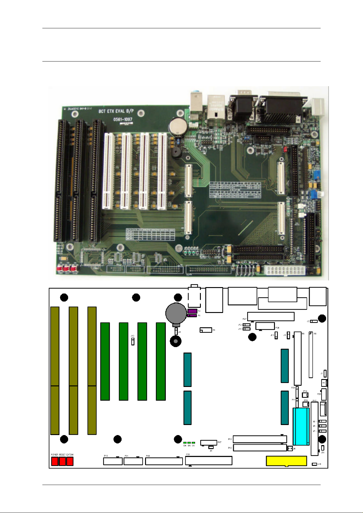
LAYOUT
The drawing below shows the layout of the BCT-ETX-EVAL-BP and shows the locations of all the
connectors and configuration jumpers.
Blue Chip Technology Limited Page 10
Page 11
BCT-ETX-EVAL-BP BACKPLANE LAYOUT
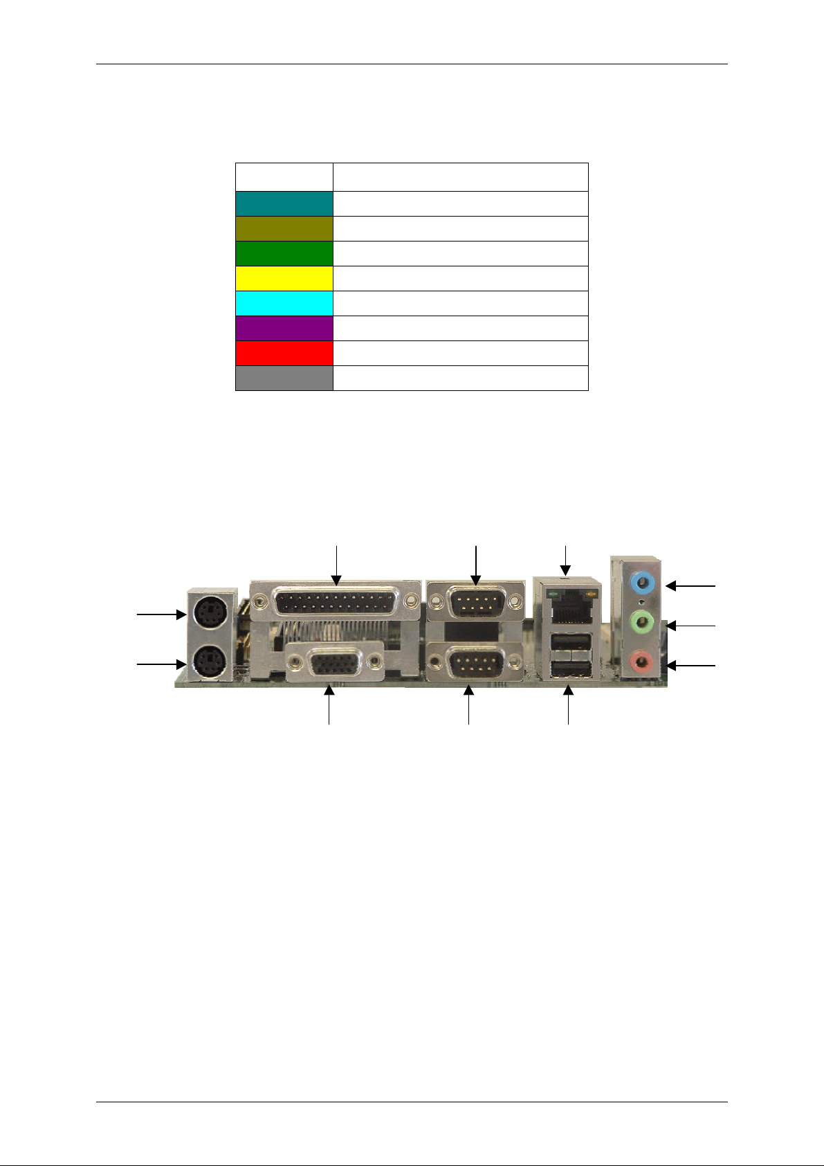
The colour-coded connectors and switches are defined as follows:
Colour Function
ETX-C3-xxx mounting connectors
ISA expansion slots
PCI Expansion slots
20 way ATX power connector
Additional ATA-Disk Chip connector
CD-ROM audio connectors
Power, reset and external SMI switches
Lithium battery
The main connectors of the BCT-ETX-EVAL-BP backplane are laid out in a similar fasthion to those found
on a standard ATX motherboard. This allows the backpane to be mounted in a standard chassis. The
connectors are laid out as follows:
Mouse
Keyboard
Parallel Port 1 COM1
Ethernet
Line In
Line Out
Microphone
USBCOM2VGA
Blue Chip Technology Limited Page 11
Page 12
BCT-ETX-EVAL-BP BACKPLANE CONFIGURATION JUMPERS
CONFIGURATION JUMPERS
The BCT-ETX-EVAL-BP backplane includes a number of user options that can be configured through the use
two and three pin jumpers. Configuration of these options requires the use of 0.1" mini-dip links.
SWITCHED VEE POLARITY SELECTION
J1 - Jumper
Link Operation
1-2 VEE is negative
2-3 VEE is positive
LCD VOLTAGE SELECTION
J2 - Jumper
Link Operation
1-2 LCD voltage is 3.3V
2-3 LCD voltage is 5V
PARALLEL PORT / FLOPPY DISK DRIVE SHARED INTERFACE
J3 - Jumper
Link Operation
1-2 Interface is the parallel port
2-3 Interface is the floppy disk drive
2½" HARD DISK MODE SELECT
J4 - Jumper
Link Operation
1-2 As per selector jumpers on drive
3-4 As per selector jumpers on drive
NOTE: These settings are only applicable to a 2½" hard disk drive connected to P12 using a 50 way cable.
Blue Chip Technology Limited Page 12
Page 13
BCT-ETX-EVAL-BP BACKPLANE CONFIGURATION JUMPERS
RESUME RESET INPUT
J5 - 2 pin header
Grounding this pin on the ETX board by closing the pins of J5 will cause a reset of the power management
logic on the ETX module.
DRIVE CONFIGURATION FOR SECONDARY IDE RIBBON CABLE CONNECTOR
J6 - Jumper
Link Operation
1-2 Connector is secondary master
2-3 Connector is secondary slave
DRIVE CONFIGURATION FOR SECONDARY 32PIN ATA-DISK CHIP CONNECTOR
J7 - Jumper
Link Operation
1-2 Connector is secondary slave
2-3 Connector is secondary master
ATA-DISK CHIP READ / WRITE CONTROL
J8 - Jumper
Link Operation
1-2 Device is read / write
2-3 Device is read only
CMOS CONTROL
J9 - Jumper
Link Operation
1-2 Normal CMOS operation
2-3 Clear CMOS
Blue Chip Technology Limited Page 13
Page 14
BCT-ETX-EVAL-BP BACKPLANE CONFIGURATION JUMPERS
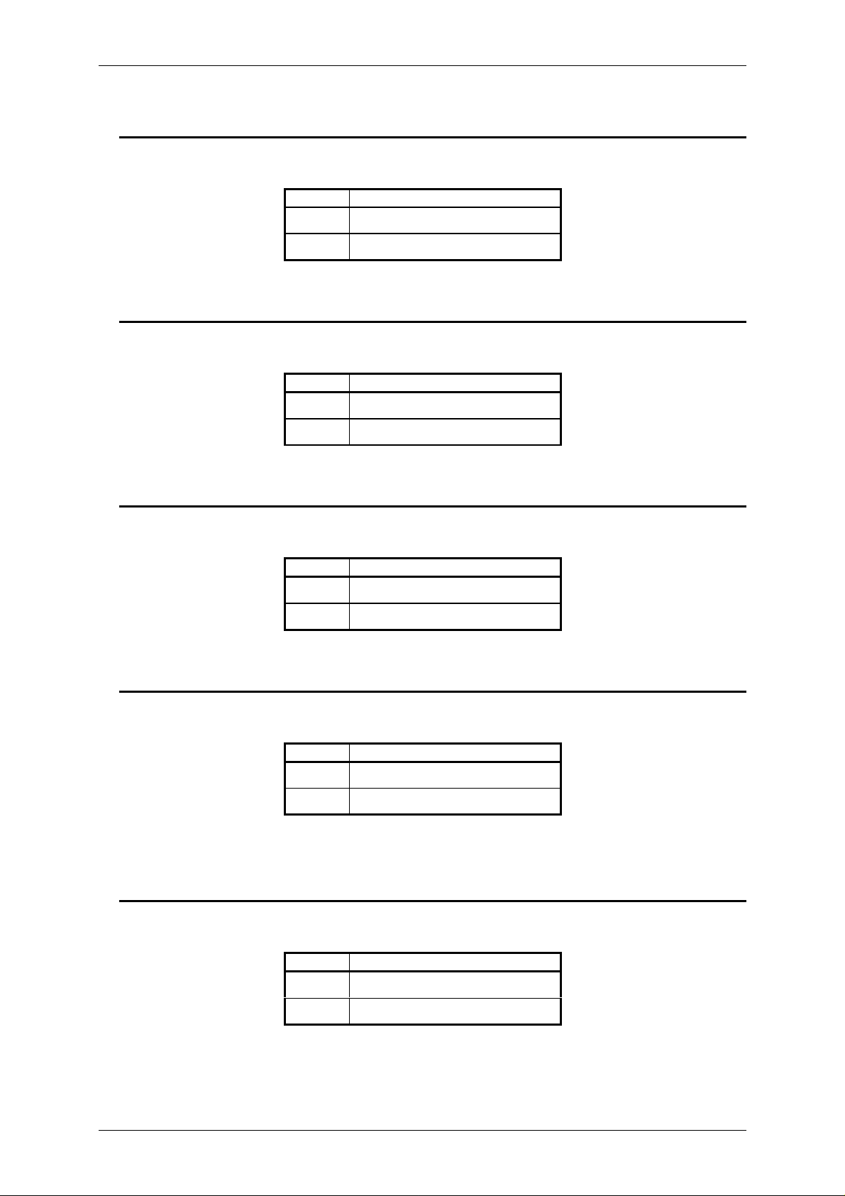
PCI VIO CONTROL
J10 - Jumper
Link Operation
1-2 PCI VIO is 5V
2-3 PCI VIO is 3.3V
COM1 RS485 DUPLEX CONTROL
J11 - Jumper
Link Operation
1-2 Full duplex
2-3 Half duplex
COM1 PROTOCOL CONTROL
J12 - Jumper
Link Operation
1-2 RS485
2-3 RS232
COM1 HALF DUPLEX CONTROL SIGNAL SELECT
J13 - Jumper
Link Operation
1-2 Use DTR for controlling direction
2-3 COM 1 is transmit only
NOTE: This must be set in position 1-2 if link J11 is in position 2-3.
5V STANDBY VOLTAGE SELECT
J14 - Jumper
Link Operation
Open 5VSB used from power supply
Closed 5VSB is linked to VCC.
Blue Chip Technology Limited Page 14
Page 15

BCT-ETX-EVAL-BP BACKPLANE CONFIGURATION JUMPERS
ATX POWER SUPPLY BYPASS
J15 - Jumper
Link Operation
Open PSU power on signal used
Closed ATX supply is always on.
Blue Chip Technology Limited Page 15
Page 16
BCT-ETX-EVAL-BP BACKPLANE CONNECTORS
CONNECTORS
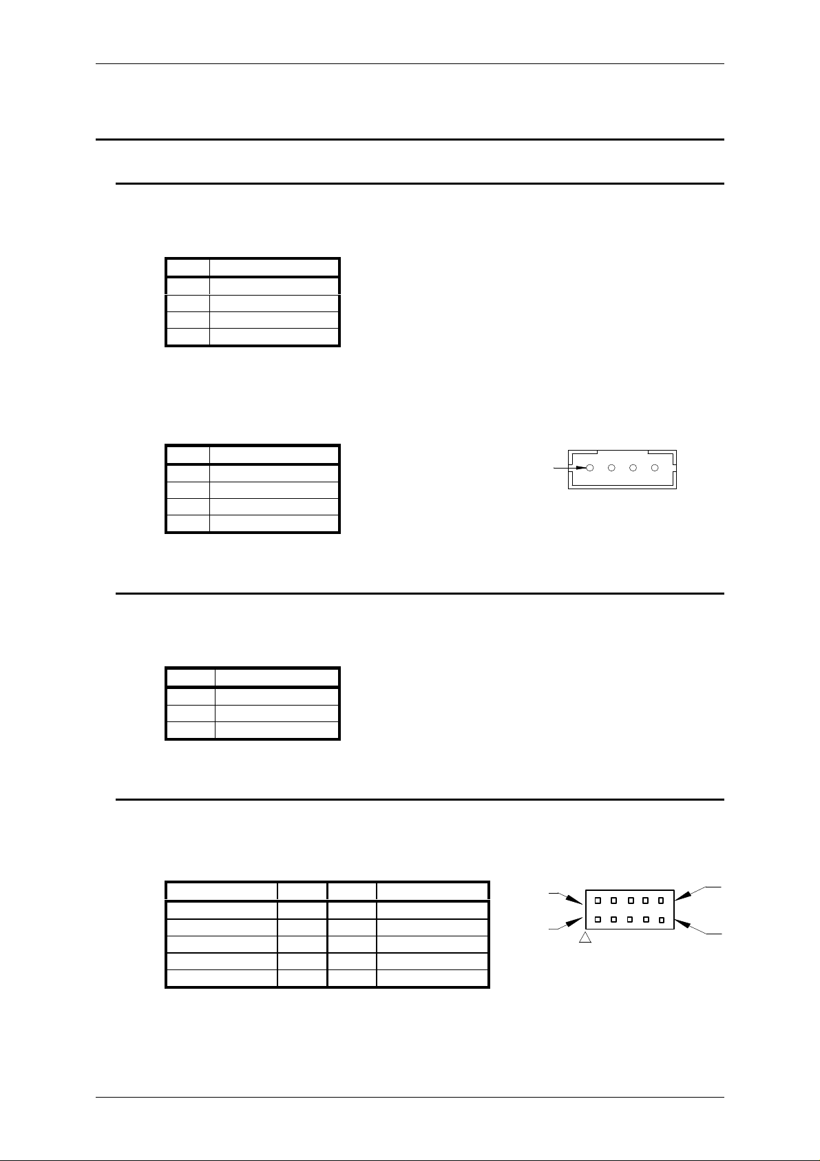
CD AUDIO INPUT
P1 - Connector: 4-way 0.1" pitch header
Mating Connector: 4-way 0.1" SIL header and crimps
Pin Signal
1 CD Left Channel
2 CD Ground
3 CD Ground
4 CD Right Channel
P2 - Connector: JST 2mm 4-way boxed pin header B 4B-PH-K/Tactpro WD.03/2
Mating Connector: JST PHR4 & SPH crimps
Pin Signal
1 CD Ground
2 CD Left Channel
3 CD Ground
4 CD Right Channel
AUDIO INPUT / OUTPUT JACKS
P3 - Connector: 3 off 3.5mm stereo jack sockets
Mating Connector: 3.5mm stereo jack plug.
Jack Signal
Blue Line input
Green Line output
Red Microphone input
USB PORTS 3 AND 4
P4 - Connector: 10-way 0.1” pitch pin header
Mating Connector: 10-way 0.1” pitch IDC or crimp socket
Pin 1
View on Connecting Pins
Signal Pin Pin Signal
Pin 2
+5V 1 2 Ground (Screen)
USB 3 Data- 3 4 Signal Ground
Pin 1
USB 3 Data+ 5 6 USB 4 Data+
Signal Ground 7 8 USB 4 Data-
View on Connecting Pins
Ground (Screen) 9 10 +5V
Blue Chip Technology Limited Page 16
Pin 10
Pin 9
Page 17

BCT-ETX-EVAL-BP BACKPLANE CONNECTORS
ETHERNET AND USB
P5 - USB Connector: Series A USB connector
Mating Connectors: Series A USB connector
Ethernet Connector: RJ-45 8-pin socket.
Mating Connector: RJ-45 8-pin plug.
Standard Pin Out.
VEE VOLTAGE CONTROL
P6 - Connector: Molex 0.1” KK 3-way pin header
Mating Connector: Molex 0.1” KK 3-way plug
Pin Signal
1 Potentiometer +ve
2 Wiper
3 Potentiometer -ve
VEE VOLTAGE OUTPUT
P7 - Connector: Molex 0.1” KK 3-way pin header
Mating Connector: Molex 0.1” KK 3-way plug
Pin Signal
1 Ground
2 Contrast
3 VEE
Blue Chip Technology Limited Page 17
Page 18
BCT-ETX-EVAL-BP BACKPLANE CONNECTORS
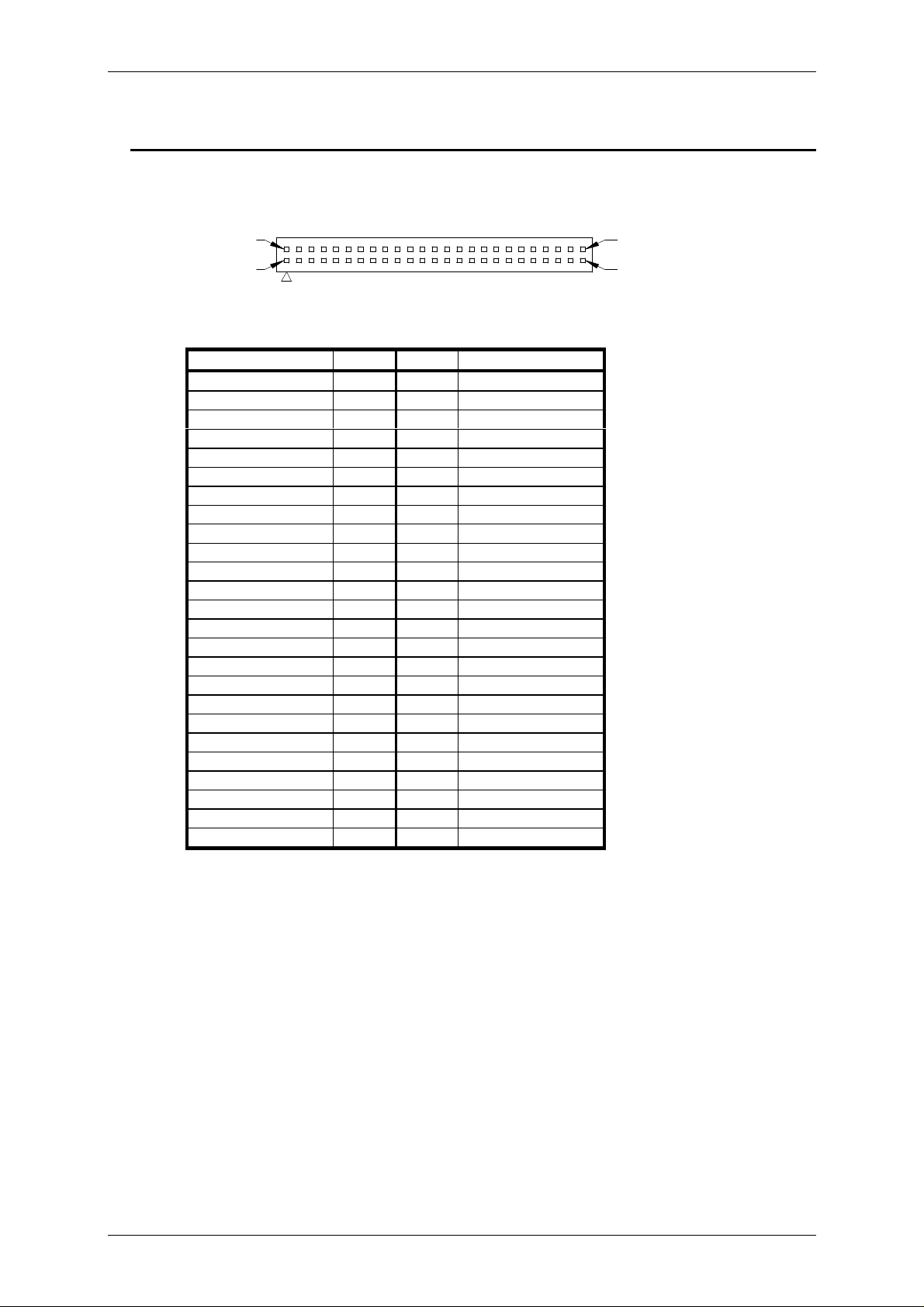
LCD TTL OUTPUT
P8 - Connector: 50-way 2mm pitch pin header
Mating Connector: 50-way 2mm pitch IDC or crimp socket
Pin 2
Pin 1
View on Connecting Pins
Signal Pin Pin Signal
Vcc 1 2 Vertical SYNC
Switched 12V 3 4 Ground
Switched VEE 5 6 Horizontal SYNC
Switched Vcc 7 8 Ground
Switched Vcc 9 10 Enable Backlight
Shift Clock 11 12 Ground
Line Pulse 13 14 Detect
Display Enable 15 16 Ground
First Line Marker 17 18 Ground
Data B5 19 20 Ground
Data B4 21 22 Not Used
Data B3 23 24 Ground
Data B2 25 26 Not Used
Data B1 27 28 Ground
Data B0 29 30 Not Used
Data G5 31 32 Ground
Data G4 33 34 Not Used
Data G3 35 36 Ground
Data G2 37 38 Not Used
Data G1 39 40 Ground
Data G0 41 42 Not Used
Data R5 43 44 Ground
Data R4 45 46 Data R0
Data R3 47 48 Ground
Data R2 49 50 Data R1
Pin 50
Pin 49
Blue Chip Technology Limited Page 18
Page 19
BCT-ETX-EVAL-BP BACKPLANE CONNECTORS
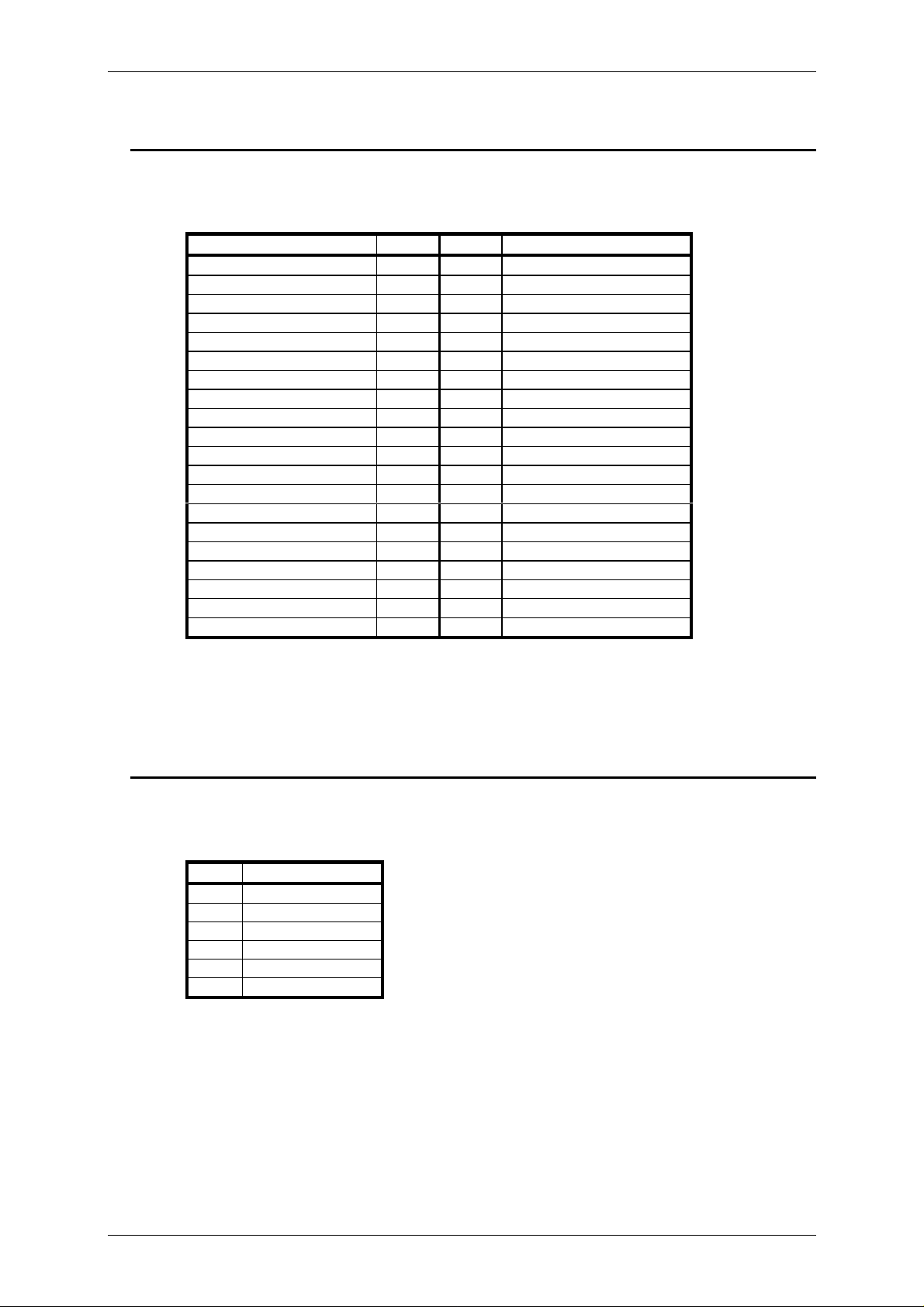
LVDS OUTPUT
P9 - Connector: 40-way 0.1" pitch pin header
Mating Connector: 40-way 0.1" pitch IDC or crimp socket
Signal Pin Pin Signal
Ground 1 2 LVDS Channel 1 T3
LVDS Channel 1 T3# 3 4 Ground
LVDS Channel 1 CLK 5 6 LVDS Channel 1 CLK#
Panel hot plug detect 7 8 LVDS Channel 1 T2
LVDS Channel 1 T2# 9 10 Ground
LVDS Channel 1 T1 11 12 LVDS Channel 1 T1#
Ground 13 14 LVDS Channel 1 T0
LVDS Channel 1 T0# 15 16 Ground
LVDS Channel 0 T3 17 18 LVDS Channel 0 T3#
Ground 19 20 LVDS Channel 0 CLK
LVDS Channel 0 CLK# 21 22 Ground
LVDS Channel 0 T2 23 24 LVDS Channel 0 T2#
Ground 25 26 LVDS Channel 0 T1
LVDS Channel 0 T1# 27 28 Digital panel power control
LVDS Channel 0 T0 29 30 LVDS Channel 0 T0#
Display VCC 31 32 Display VCC
Panel contrast control 33 34 Enable backlight
Not used* 35 36 Not used*
Not used 37 38 Not used
12V 39 40 12V
*On some ETX processor boards the signals on pins 35 and 36 of connector P9 are data and clock pins
respectively for an I2C EEPROM interface for LCD panel configuration information.
SYSTEM MANAGEMENT BUS
P10 - Connector: Molex 0.1” KK 6-way pin header
Mating Connector: Molex 0.1” KK 6-way plug
Pin Signal
1 VCC
2 SM Bus Clock
3 SM Bus Data
4 SM Bus Alert
5 Not Used
6 Ground
Blue Chip Technology Limited Page 19
Page 20

BCT-ETX-EVAL-BP BACKPLANE CONNECTORS
I2C BUS
P11 - Connector: 4-way 0.1” pin header
Mating Connector: 4-way 0.1” SIL and crimps
Pin Signal
1 VCC
2 I2C Clock
3 I2C Data
4 Ground
50 WAY PRIMARY IDE CONNECTOR
P12 - Connector: 40-way 2mm pin header.
Mating connector: 40-way 2mm (IDC) socket.
Signal Pin No Pin No Signal
J4 - Pin 1 1 2 J4 - Pin 2
J4 - Pin 3 3 4 J4 - Pin 4
Not Used 5 6 Not Used
-Reset 7 8 Ground
Data bit 7 (HD) 9 10 Data bit 8 (HD)
Data bit 6 (HD) 11 12 Data bit 9 (HD)
Data bit 5 (HD) 13 14 Data bit 10 (HD)
Data bit 4 (HD) 15 16 Data bit 11 (HD)
Data bit 3 (HD) 17 18 Data bit 12 (HD)
Data bit 2 (HD) 19 20 Data bit 13 (HD)
Data bit 1 (HD) 21 22 Data bit 14 (HD)
Data bit 0 (HD) 23 24 Data bit 15 (HD)
Ground 25 26 Not used
Drive Request 27 28 Ground
-IO Write (HD) 29 30 Ground
-IO Read (HD) 31 32 Ground
Drive Ready 33 34 Not Used
Drive Acknowledge 35 36 Ground
IRQ14 37 38 HDIOCS16
Address 1 (HD) 39 40 Not Used
Address 0 (HD) 41 42 Address 2 (HD)
-Chip Select 0 (HD) 43 44 -Chip Select 1 (HD)
PLED 45 46 Ground
5V 47 48 5V
Ground 49 50 Ground
40 WAY PRIMARY IDE CONNECTOR
P13 - Connector: 40-way 0.1" pitch header
Mating Connector: 40-way 0.1" pitch IDC socket
Standard Pin Out.
Blue Chip Technology Limited Page 20
Page 21
BCT-ETX-EVAL-BP BACKPLANE CONNECTORS
Pin 12
KEYBOARD INHIBIT
P14 - Connector: Molex 0.1” KK 2-way pin header
Mating Connector: Molex 0.1” KK 2-way plug
Pin Signal
1 Keyboard inhibit
2 VCC
40 WAY SECONDARY IDE CONNECTOR
P15 - Connector: 40-way 0.1" pitch header
Mating Connector: 40-way 0.1" pitch IDC socket
Standard Pin Out.
BATTERY LOW
P16 - Connector: Molex 0.1” KK 2-way pin header
Mating Connector: Molex 0.1” KK 2-way plug
Pin Signal
1 Ground
2 Battery low
NOTE: This signal can be used to notify the ETX processor card that the battery voltage is low, or can be
used for other notification events.
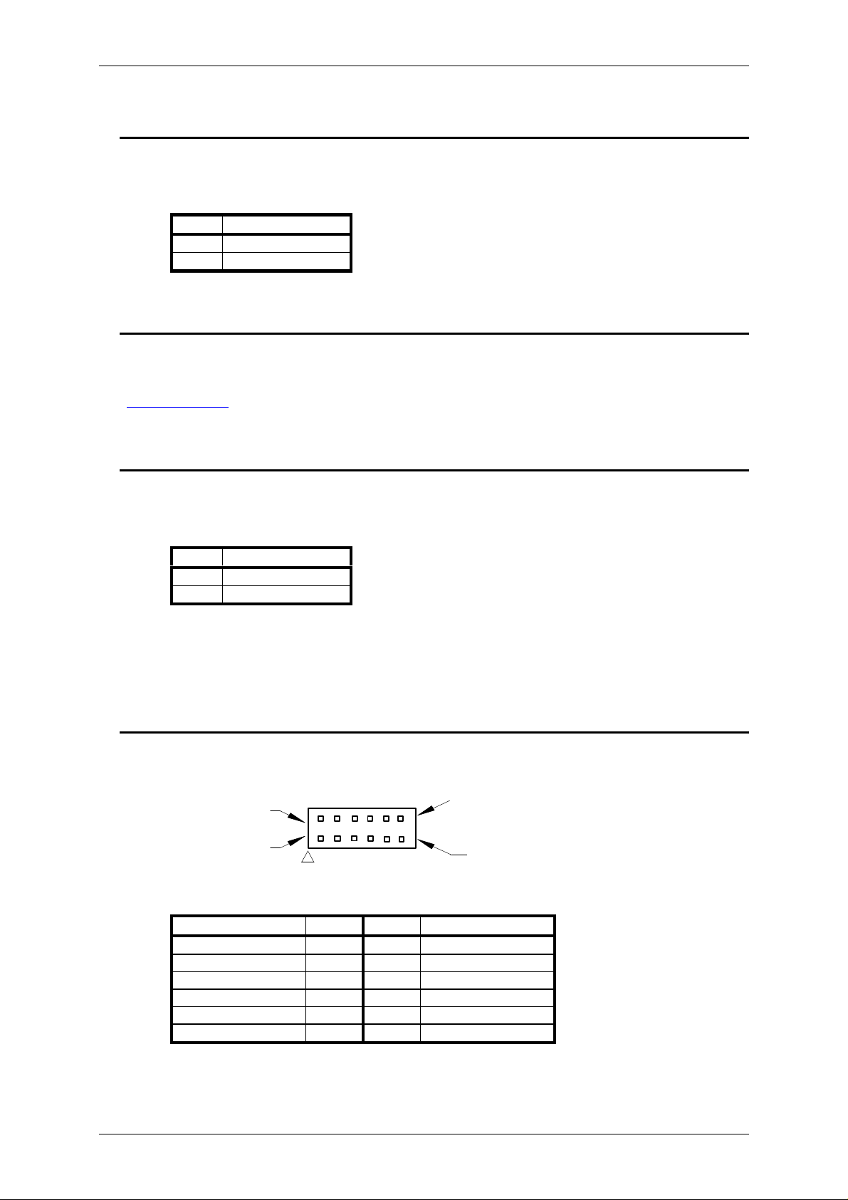
UTILITIES
P17 - Connector: 12-way 0.1" pitch pin header
Mating Connector: 12-way 0.1" pitch IDC or crimp socket
Pin 2
Pin 1
View on Connecting Pins
Pin 11
Signal Pin Pin Signal
HDD Activity +ve 1 2 HDD Activity -ve
Power LED +ve 3 4 Ground
Power Switch 5 6 Ground
Reset Button 7 8 Ground
External SMI 9 10 Ground
Speaker +ve 11 12 Speaker -ve
Blue Chip Technology Limited Page 21
Page 22

BCT-ETX-EVAL-BP BACKPLANE CONNECTORS
PARALLEL PORT 2
P18 - Connector: 2x13-way 0.1” pitch pin header
Mating Connector: 2x13-way 0.1" pitch IDC socket
Standard Pin Out.
NOTE: This connector provides an additional parallel port when the SMC SuperIO device is fitted.
SERIAL PORT 3
P19 - Connector: 5x2-way 0.1” pitch pin header
Mating Connector: 5x2-way 0.1" pitch IDC socket
Standard Pin Out.
NOTE: This connector provides an additional RS232 serial port when the SMC SuperIO device is fitted.
SECONDARY FLOPPY DISK INTERFACE
P20 - Connector: 34-way 0.1" pitch header
Mating Connector: 34-way 0.1" pitch IDC socket
Standard Pin Out
NOTE: This connector provides a full implementation of the floppy disk interface when the SMC SuperIO
device is fitted.
SERIAL PORT 4
P21 - Connector: 5x2-way 0.1” pitch pin header
Mating Connector: 5x2-way 0.1" pitch IDC socket
Standard Pin Out.
NOTE: This connector provides an additional RS232 serial port when the SMC SuperIO device is fitted.
SERIAL PORT 1 (RS232) AND SERIAL PORT 2
P22 - Connector: Standard 9 way male D type
Mating Connector: Standard 9 way female D type
Standard Pin Out.
Blue Chip Technology Limited Page 22
Page 23

BCT-ETX-EVAL-BP BACKPLANE CONNECTORS
IRDA
P23 - Connector: 5-way 0.1” pitch pin header
Mating Connector: 5-way SIL 0.1” socket
Pin Signal
1 5V
2
KEY
3 IR RX
4 0V
5 IR TX
SERIAL PORT 1 (RS485)
P24 - Connector: 10-way 0.1" pitch pin header
Mating Connector: 10-way 0.1" pitch IDC socket
Signal Pin
No.
Pin
No.
Signal
+Rx FDX 1 2 +Term. 10K to +5V
-Rx FDX 3 4 No Connect
+Tx FDX,
5 6 No Connect
+Rx/+Tx HDX
-Tx FDX,
7 8 No Connect
-RX/-Tx HDX
-Term. 10K to Gnd 9 10 No Connect
ATX POWER
P25 - Connector: 20-way ATX power connector
Mating Connector: 20-way ATX power supply connector
Note: The power on signal can be bypassed to allow the power supply to be always on by fitting a link to
jumper J15.
PARALLEL PORT 1 / VGA
P26 - LPT Connector: 25-way D-type socket
Mating Connector: 25-way D-type plug
P26 - VGA Connector: High-density 15-pin D-type socket.
Mating Connector: High-density 15-pin D-type plug.
Standard Pin Out
NOTE: The parallel port interface is shared with the primary floppy disk interface and is selected using
jumper J3.
Blue Chip Technology Limited Page 23
Page 24
BCT-ETX-EVAL-BP BACKPLANE CONNECTORS
PRIMARY FLOPPY DISK INTERFACE
P27 - Connector: 34-way 0.1" pitch header
Mating Connector: 34-way 0.1" pitch IDC socket
Standard Pin Out
NOTE: This interface is shared with parallel port 1 and is selected using jumper J3.
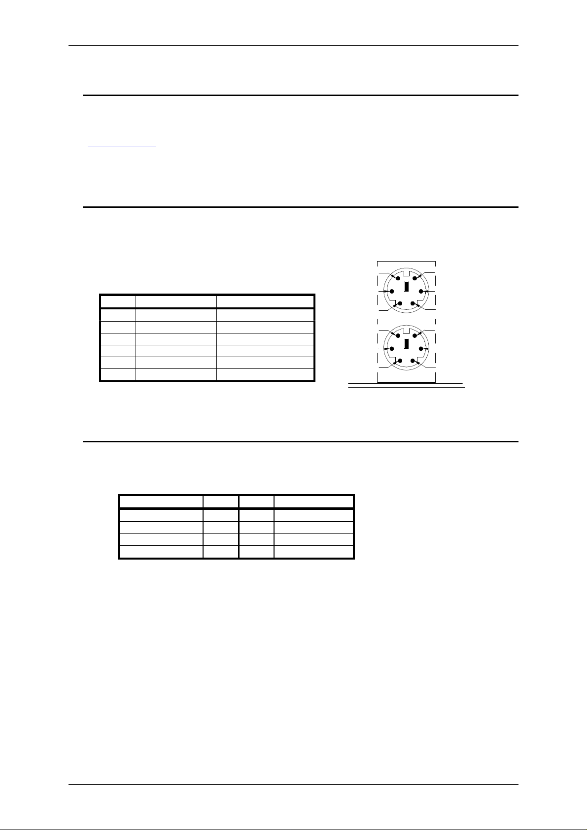
PS/2 MOUSE AND KEYBOARD
P28 - Connector: PS/2 6-pin mini-DIN socket.
Mating Connector: PS/2 keyboard or mouse connector.
Pin Upper Lower
1 Mouse Data Keyboard Data
2 Not Used Mouse Data
3 Ground Ground
4 +5V +5V
5 Mouse Clock Keyboard Clock
6 Not Used Mouse Clock
View on Connecting Sockets
COMPOSITE / S-VIDEO OUTPUT
P29 - Connector: 8-way 0.1" pitch pin header
Mating Connector: 8-way 0.1" pitch IDC socket or crimps
Signal Pin Pin Signal
Intensity 1 2 Ground
Chroma 3 4 Ground
Composite Sync 5 6 Ground
Composite Video 7 8 Ground
Pin 6
Pin 4
Pin 2
Pin 6
Pin 4
Pin 2
Pin 5
Pin 3
Pin 1
Pin 5
Pin 3
Pin 1
Mouse
Keybd
Blue Chip Technology Limited Page 24
Page 25

BCT-ETX-EVAL-BP BACKPLANE STANDARD CONNECTORS
STANDARD CONNECTORS
The attached guide is a general reference point for the following standard pin-outs.
Standard Pin Out
Blue Chip Technology Limited Page 25
Page 26

BCT-ETX-EVAL-BP BACKPLANE AMENDMENT HISTORY
AMENDMENT HISTORY
Issue Level Issue Date Author Amendment Details
0.1 02/07/2003 AJP First Draft Issue
Blue Chip Technology Limited Page 26
 Loading...