


Page | 1
Scala L3
Small Form-Factor Player
User Guide
Document Reference: Product User Guide
Document Issue: 1.0

Scala L3 Table Of Contents
Page | 2
Contents
Copyright ............................................................................................................................................................ 3
Limitations of Liability ....................................................................................................................................... 3
Trademarks ......................................................................................................................................................... 3
Regulatory Statements ........................................................................................................................................ 4
Safety Warning for North America .................................................................................................................... 4
Manual Organisation .......................................................................................................................................... 5
Introduction ........................................................................................................................................................ 6
Specification ....................................................................................................................................................... 7
General Precautions ............................................................................................................................................ 9
Electro-Static Discharges .................................................................................................................................... 9
On-Board Battery ............................................................................................................................................... 9
BIOS & CMOS Memory .................................................................................................................................. 10
Electromagnetic Compatibility ......................................................................................................................... 10
Quick Start ........................................................................................................................................................ 11
External Connections ........................................................................................................................................ 12
Internal Connections ......................................................................................................................................... 12
Jumpers ............................................................................................................................................................. 13
CMOS Clear ................................................................................................................................................. 13
Front Panel Connector ...................................................................................................................................... 13
Upgrading Hardware ............................................................................................................................................ 14
Warning ........................................................................................................................................................... 14
Upgrade Options ............................................................................................................................................ 14
Outline Drawing ............................................................................................................................................... 15
Adding / Removing Mounting Brackets ........................................................................................................... 16
Removing / Fitting the Cover Lid ..................................................................................................................... 16
Replacing / Fitting the Disk on Module ............................................................................................................ 17
Replacing the HDD .......................................................................................................................................... 18
Replacing the On/Off Switch Assembly ........................................................................................................... 18
PCI Expansion .................................................................................................................................................. 19
Optional Wi-Fi .................................................................................................................................................. 22
Installing Operating Systems ................................................................................................................................ 23
BIOS Setup ........................................................................................................................................................... 24
Main Menu ................................................................................................................................................... 24
CMOS Features ............................................................................................................................................ 26
Advanced BIOS Features ............................................................................................................................. 26
Advanced Chipset Features .......................................................................................................................... 27
Integrated Peripherals ................................................................................................................................... 28
Power Management Setup ............................................................................................................................ 29
Miscellaneous Control Configurations ......................................................................................................... 30
PC Health Status ........................................................................................................................................... 30
Thermal Throttling ....................................................................................................................................... 31
Maintenance...................................................................................................................................................... 32
Replacing the Battery ................................................................................................................................... 32
Fuses ............................................................................................................................................................. 32
Amendment History ......................................................................................................................................... 33

Scala L3 Introduction
Page | 3
Copyright
All rights reserved. No part of this publication may be reproduced, stored in any retrieval system, or
transmitted, in any form or by any means, electronic, mechanical, photocopied, recorded or otherwise, without
the prior permission, in writing, from the publisher. For permission in the UK please contact Blue Chip
Technology.
Information offered in this manual is believed to be correct at the time of printing. Blue Chip Technology
accepts no responsibility for any inaccuracies. The information contained herein is subject to change without
notice. There are no express or implied licences granted herein to any intellectual property rights of Blue Chip
Technology Ltd.
Limitations of Liability
In no event shall Blue Chip Technology be held liable for any loss, expenses or damages of any kind
whatsoever, whether direct, indirect, incidental or consequential, arising from the design or use of this product
or the support materials supplied with this product. If this product proves to be defective, Blue Chip
Technology is only obliged to replace or refund the purchase price at Blue Chip Technology's discretion
according to their Terms and Conditions of Sale.
Trademarks
All trademarks and registered names acknowledged.
IBM, PC, AT and PS/2 are trademarks of International Business Machines Corporation (IBM).
Intel is a registered trademark of Intel Corporation.
All Intel processors are registered trademarks of Intel Corporation.
MSDOS and WINDOWS are registered trademarks of the Microsoft Corporation.
is a registered trademark of SCALA, Inc.

Scala L3 Introduction
Page | 4
Regulatory Statements
CE
This product meets the essential protection requirements of the European EMC Directive (89/336/EEC) and its
amending Directives, and the Low Voltage Directive 73/23/EEC, and is eligible to bear the CE mark.
Warning
This is a Class A product. In a domestic environment this product may cause radio
interference in which case the user may be required to take adequate measures.
FCC
NOTE:
This equipment has been tested and found to comply with the limits for a Class A digital device, pursuant to
Part 15 of the FCC Rules. These limits are designed to provide reasonable protection against harmful
interference when the equipment is operated in a commercial environment. This equipment generates, uses, and
can radiate radio frequency energy and if not installed and used in accordance with the instruction manual, may
cause harmful interference to radio communications. Operation of this equipment in a residential area is likely to
cause harmful interference in which case the user will be required to correct the interference at his own expense.
WARNING:
Changes or modifications not expressly approved by the manufacturer could void the user's authority to operate
the equipment.
Safety Warning for North America
If the power lead (cord) is not supplied with the computer, select a power lead according to your local electrical
regulations. In the USA use a 'UL listed' lead. In Canada use a CSA approved or 'cUL listed' lead.
Si le cordon secteur n'est pas livré avec l'ordinateur, utiliser un cordon secteur en accord avec votre code
electrique nationale. En l'Etat Unis utiliser un cordon secteur 'UL listed'. En Canada utiliser un cordon secteur
certifié CSA, ou 'cUL listed'.

Scala L3 User Guide Organisation
Page | 5
Manual Organisation
This manual describes in detail the Scala L3 Small Form-Factor PC.
We have tried to include as much information as possible but we have not duplicated information that is
provided in the standard IBM Technical References, unless it proved to be necessary to aid in the understanding
of the product.
The manual is sectioned as follows:
Introduction;
Overview, listing the unit's features and specification;
Installation, including what software to install
Layout, showing where the various connectors are located, and their pin-out details;
How to upgrade the system;
Bios Setup
Maintenance details
We strongly recommend that you study this manual carefully before attempting to interface with the L3 or
change the standard configurations. Whilst all the necessary information is available in this manual we would
recommend that unless you are confident, you contact your supplier for guidance. IT IS PARTICULARLY
IMPORTANT THAT YOU READ THE SECTION 'PRECAUTIONS' BEFORE HANDLING ANY
COMPONENTS INSIDE THE UNIT.
If you have any suggestions or find any errors concerning this manual and want to inform us of these, please
contact our Technical Services department with the relevant details.

Scala L3 Product Summary
Page | 6
Introduction
The SCALA L3 is a powerful slim-line AMD AM2/AM3 based Personal Computer (PC) specifically designed
to drive large plasma and other large displays panels. Although specifically configured to support Scala Player
software, the units are suitable for a number of PC related applications, including as a small form factor PC. The
unit is self-contained requiring as a minimum, only a power connection and a display.
The basic unit comprises a highly integrated computer board employing the AMD 780G North bridge and
SB700 south bridge chipsets. Memory options allow up to 2GB of ultra fast 800/667 MHz unbuffered ECC/
non-ECC DDR2 SODIMM SDRAM. Storage is provided by a Serial ATA II 3Gb/s hard disk drive.
The integrated HD 3200 graphics supports Microsoft® DirectX 10.0, dual VGA out (RGB and DVI/HDMI).
This also provides HD Audio support via the HDMI connector. Alternatively, a Realtek ALC662-6 HD device
provides HD Audio via standard Audio ports. Gigabit Ethernet is provided by the RTL 8111C device
The unit is housed in a strong sheet-steel enclosure providing both mechanical and EMC protection. The unit
may be mounted on the plasma display, or separately to suit the particular installation. Mounting kits are
available for specific plasma displays, wall or desktop.
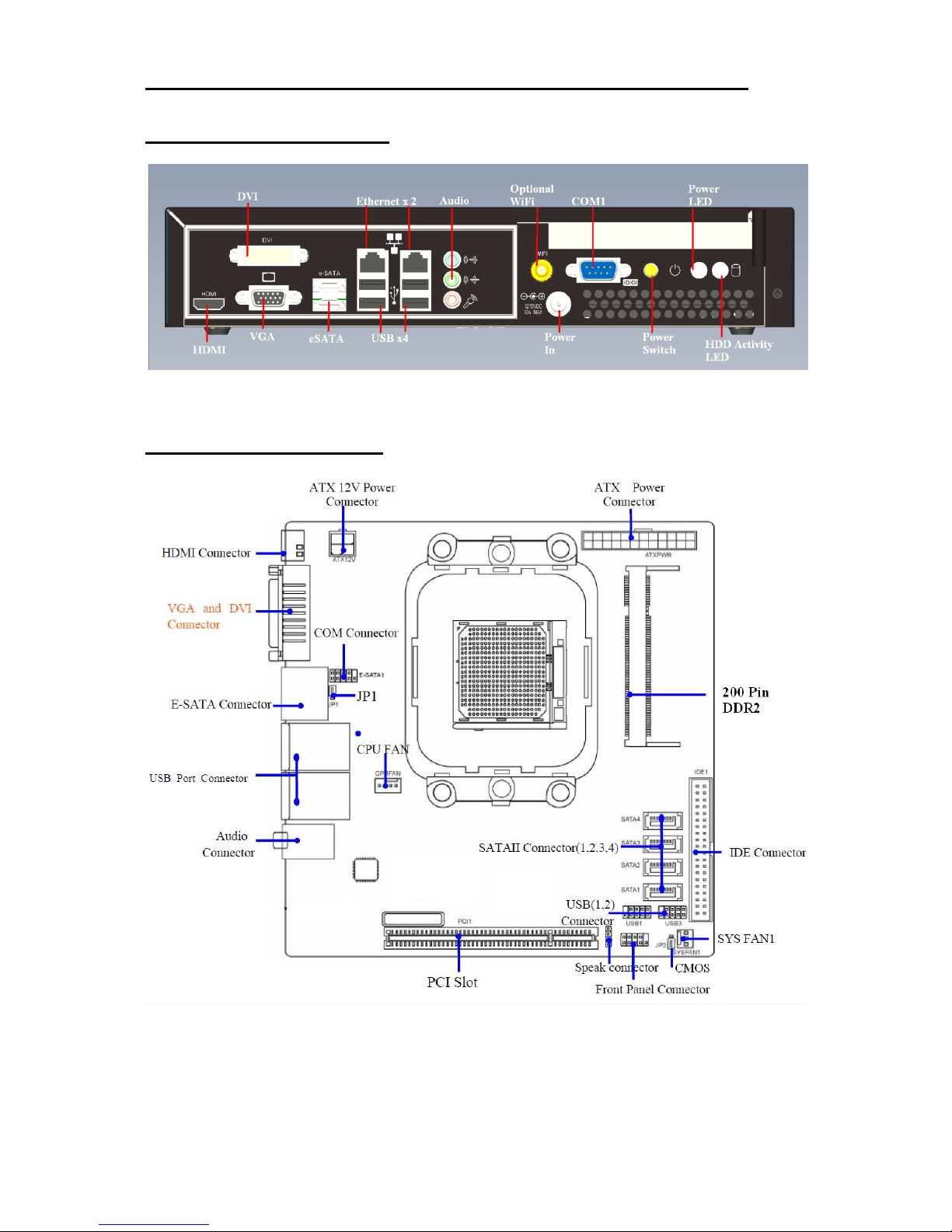
Most connectors are on the front face of the chassis. There are connectors for a standard analogue VGA display,
a standard Digital Display (Via HDMI or DVI connector), one serial port, four USB (2.0) ports, two Ethernet
(10/100/1Gb) LAN ports, two eSATA ports and Line-In, Line-Out, MIC-In audio connectors.
The DC power inlet connector is also on the front of the chassis, supporting a standard ID 2.5mm and OD
5.5mm short termination plug.
External indicators and controls on the front face of the chassis are limited to a hard drive activity LED, a power
on LED and a power/standby push-button switch. The LAN connectors also include LEDs indicating a
connection and data rate.

Scala L3 Specification
Page | 7
Specification
CPU:
AMD Socket AM2+ / AM3
Chipset:
AMD 780G and SB700
Graphics Controller:
Integrated HD 3200
RGB, DVI / HDMI
Maximum resolution of 2048x1536 for VGA output
Picture rotation 0, 90, 180, 270 degrees
BIOS:
8Mb Flash EEPROM with LAN Boot, PnP, ACPI, DMI
Memory:
Dual Channel memory Architecture
1 x 200-pin SODIMM socket supporting up to 2GB of unbuffered
non-ECC 800/667 MHz DDR2 memory modules
LAN
Dual RTL 8111C, supporting 10/100/1Gb rates
Audio:
Realtek ALC662 plus integrated ATI
Expansion:
Single PCI Expansion supporting low power/Short PCI cards
Primary Storage:
One 3½” SATA II hard disk drive
Optional Storage:
One 2½” SATA Solid State HDD or One Disk On Module
External I/O:
Standard VGA connector
Digital HDMI connector
Digital DVI-D connector
2 x eSATA connectors
9-way Serial connector (16550 compatible)
2 x RJ-45 10/100/1Gb Base-T Ethernet LAN connector
Line Out, MIC-in, Line-In/SPDIF
4 x USB 2.0 connectors
Indicators:
Power On LED, Hard Drive Activity LED
Control:
Power Standby push button switch
System Management:
CPU & System temperature monitoring
Voltage monitoring of CPU Core, DRAM, NB
Power:
12V DC Internal Power
External power via OD5.5mm, ID2.5mm short Jack Socket *
Typical Power Consumption: 60W based on 160Gb HDD, 2Gb RAM,
AMD 5050e X2 CPU with XP professional running High CPU
loading
*Note: the plug should be no longer than 10mm long to avoid damaging the socket housing

Scala L3 Specification
Page | 8
Environmental Conditions:
Operating temperature range +0°C 1 to +40°C in free air
Storage temperature range -20°C to +70°C
Relative humidity 10-85% non-condensing
Shock and vibration compatible with light industrial usage
1
Due to mechanical parts, if a hard drive is fitted, the unit must not be powered on when the ambient
temperature is less than 5°C
Construction:
Painted zinc-plated sheet steel, welded and riveted construction
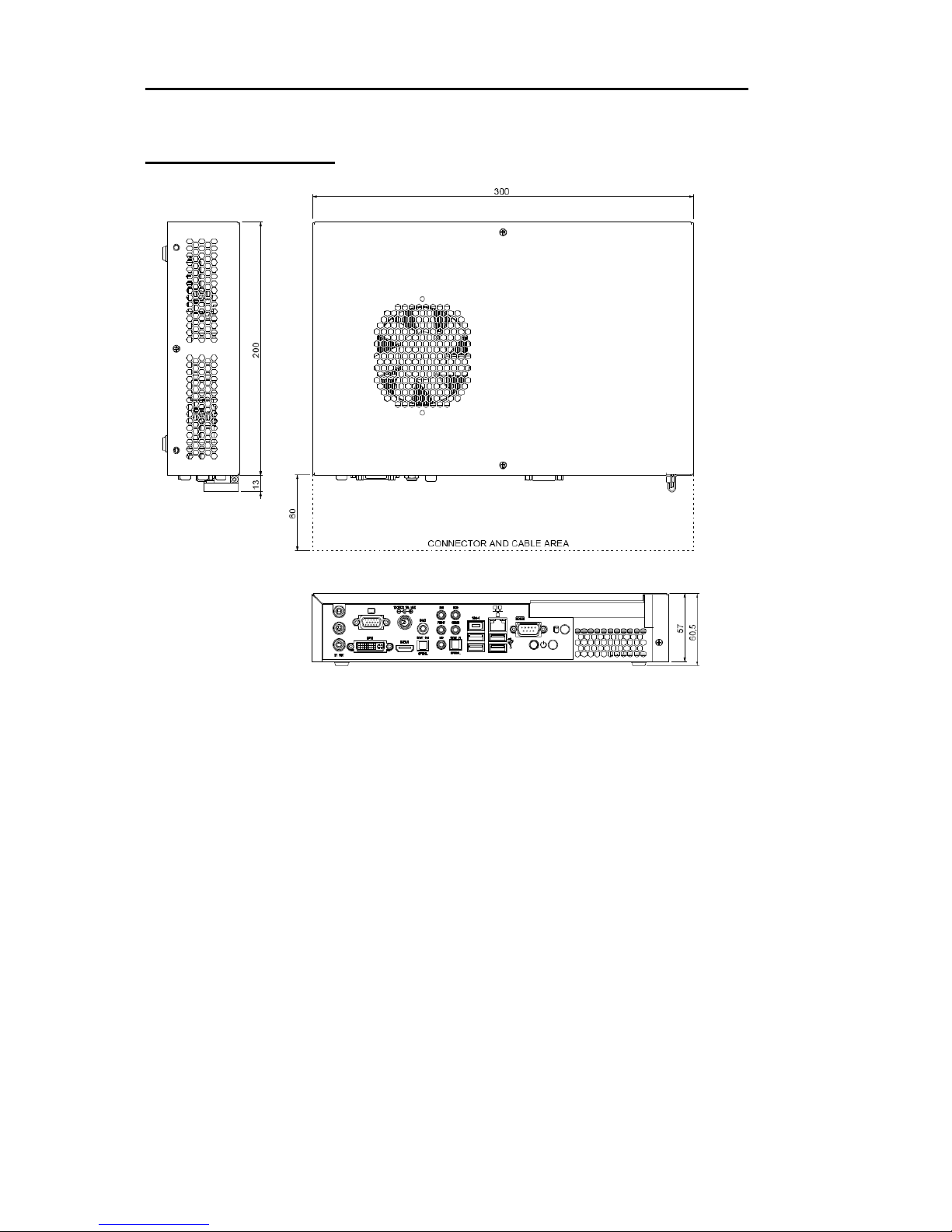
Dimensions:
300 x 200 x 57 mm, excluding the mounting brackets
Air vents must not be obstructed. A minimum gap of 25mm
between faces containing vents and any adjacent items is
recommended.

Scala L3 Precautions
Page | 9
General Precautions
Your Single Board Computer is susceptible to damage by electrostatic discharges. In order to avoid damage,
you should work at an anti-static bench and observe normal anti-static precautions. Wear an anti-static wrist
strap connected to an earth point before opening any packaging.
Where a wrist strap is not available, discharge any static charge you may have built-up by touching an earth
point. Avoid any further movement that could build up another static charge. Touch an earth point from time to
time to avoid further build-up, and remove the items from their anti-static bags only when required
Electro-Static Discharges
If you are going to open up the unit, it is important to realise that the devices on the cards within this unit can be
damaged by static electricity. Bear in mind that the damage caused by static electricity may vary from total
destruction to partial damage, which may not be immediately obvious. This could have an effect on the
product's reliability and warranty. Before opening the chassis, ensure that you take necessary static precautions.
Ideally you should work at an anti-static bench and wear an approved wrist strap or if that is not possible, touch
a suitable ground to discharge any static build up before touching the electronics. This should be repeated if the
handling continues for any length of time.
If it is necessary to remove a board or electronic assembly, place it into an anti-static bag. This will prevent any
static electricity build up damaging the board. Metallised bags are preferred. Do not use black anti-static bags
for any item containing a battery because these tend to be conductive and will discharge the battery.
On-Board Battery
The processor board is fitted with a Lithium battery. Great care should be taken with this type of battery. If the
battery is mistreated in any way there is a very real possibility of fire, explosion, and personal harm. Under NO
circumstances should it be short-circuited, exposed to temperatures in excess of 100 °C or burnt, immersed in
water, recharged or disassembled.
Expired batteries remain hazardous and must be disposed of in a safe manner, according to local regulations.
Le panneau de processeur est équipé d’une batterie de lithium. Le grand soin devrait être pris avec ce type de
batterie. Si la batterie est mistreated il y a de dans de toute façon un possibility très vrai du feu, d’expolosion et
de mal personnel. Dans au cunes circonstances il est sous peu circuité, exposé aux températures au dessus de
100 degrés de centrigrade ou brûlé, immergé dans l’eau, rechargée ou dissassambled.
Les batteries expirées restent dazaedous et doivent être reejetées d’une façon sûre, selon des règlements locaux.

Scala L3 Precautions
Page | 10
BIOS & CMOS Memory
Please be aware that with personal computer products, it is possible to create configurations within the CMOS
memory that make booting impossible. If this should happen, clear the CMOS settings; (see the description of
the Jumper Settings for details).
Electromagnetic Compatibility
This product meets the requirements of the European EMC Directive (89/336/EEC) and is eligible to bear the
CE mark.
It has been assessed operating in a Blue Chip Technology Industrial PC. However, because the board can be
installed in a variety of computers, certain conditions have to be applied to ensure that the compatibility is
maintained. Subject to those conditions, it meets the requirements for an industrial environment (Class A
product).
Connector bodies must be securely connected to the enclosure.
The external cabling to boards causes most EMC problems. It is imperative that any external cabling to
the board is totally screened, and that the screen of the cable connects to the metal end bracket of the
board or the enclosure and hence to earth. It is recommended that round, screened cables with a braided
wire screen are used in preference to those with a foil screen and drain wire. Use metal connector shells
that connect around the full circumference of the cable screen: they are far superior to those that earth
the screen by a simple “pig-tail”.
The keyboard and mouse will play an important part in the compatibility of the processor card since
they are ports into the board. Similarly, they will affect the compatibility of the complete system. Fully
compatible peripherals must be used otherwise the complete system could be degraded. They may
radiate or behave as if keys/buttons are pressed when subject to interference. Under these
circumstances it may be beneficial to add a ferrite clamp on the leads as close as possible to the
connector. A suitable type is the Chomerics type H8FE-1004-AS.
USB cables should be high quality screened types.
Ensure that the screens of any external cables are bonded to a good RF earth at the remote end of the
cable.
Failure to observe these recommendations may invalidate the EMC compliance.

Scala L3 Quick Start
Page | 11
Quick Start
The following sections explain how to install your Scala L3 Computer.
First ensure that you are familiar with the associated Scala Player Setup Guide which is supplied with the unit. It
contains important information regarding the configuration and operation of the unit.
The Scala Player is supplied with an image containing the Scala Player software as well as a number of Pre Set
User Accounts.
The necessary hardware required to support the software is all included so there should be no need to add any
additional hardware, however, instructions are provided later in the document for fitting or replacing any
hardware.
When positioning the unit in its surroundings, care should be taken not to restrict the natural airflow of the unit.
As a desktop unit, cool air enters through the top vent and warm air is vented from the sides and the rear. When
attaching cables to the rear of the chassis do not press or fold them too tightly. Doing so can cause fractures
inside the cables resulting in poor signal quality.
The unit may be used free-standing, but it is recommended that it be securely mounted to avoid accidental
damage. The actual mounting details will vary depending upon the application.
There are four M3 tapped holes on each end of the chassis for mounting brackets, etc. Do not use screws longer
than those supplied to mount the unit, otherwise internal damage may result. If alternative screws are used,
please ensure that they do not enter the chassis by more than 5mm, otherwise internal damage may result.
If you did not purchase mounting brackets but find that you actually need them, then contact
sales@bluechiptechnology.co.uk with details of the particular mounting arrangement you require to see
if something suitable already exists.
If the unit is to be used free-standing fit the adhesive synthetic rubber feet to the base. These will prevent the
unit slipping on a smooth surface.
Connect the display to the VGA, DVI or HDMI connector, and connect any other signals, e.g. LAN. Connect
the power lead to a suitable AC power source. It is recommended that the supply be fused at 5A. [Please note
that the Scala L3 does not support Dual Digital operation]
Press the 'Power On' button and check that the unit boots up.
Scala L3 Installation
Page | 12
External Connections
Figure 1: External Connections
Internal Connections
Figure 2: Internal Connectors
Scala L3 Installation
Page | 13
Jumpers
The processor board used in the SCALA L3 PC is largely free of selection jumpers. Most settings are controlled
from the BIOS, and stored in the CMOS memory. Only the following jumpers are significant.
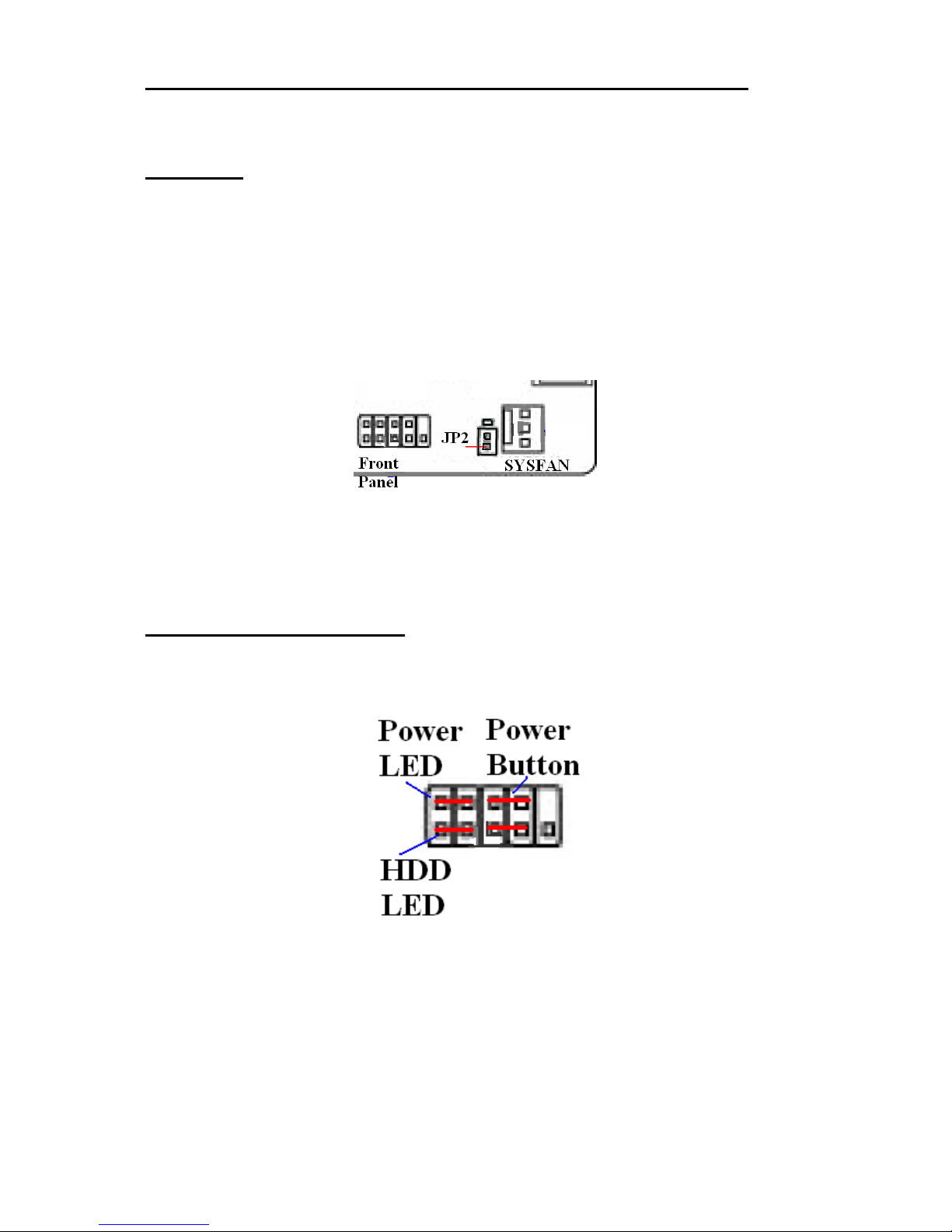
CMOS Clear
To clear the CMOS memory, first switch off the PC power, then locate the 3-pin header labelled ‘CLRTC’ on
the processor board which is beside the SYSFAN and Front Panel connectors. Remove the link shorting pins 1
and 2, and place it on pins 2 and 3 for about 5 - 10 seconds. Remove the link and replace it in its original
position. The CMOS has now been cleared and the BIOS will be reset to the default settings.
Having no link fitted is an invalid option.
Figure 3: CMOS Jumper Default
Front Panel Connector
The front panel connector is shown in Figure 3 above. It is wired as follows
Figure 4: Front Panel Connector

Scala L3 Installation
Page | 14
Upgrading Hardware
Warning
Before attempting any upgrade to the SCALA L3 computer, please read the section "Precautions".
For your personal safety it is important that you ensure that the unit is switched off, and the DC supply is
disconnected.
For the safety of the equipment, it is important that you observe electrostatic discharge precautions. Do not
remove items from anti-static bags until necessary.
When making any internal changes to the computer, it is imperative that the internal cables follow the original
routes and additional cables are installed as described. Failure to observe this requirement could restrict the
airflow through the unit and cause overheating problems.
Upgrade Options
Due to the small footprint of the unit, there are minimal options to upgradeable. Changing the AMD CPU may
require a BIOS upgrade for the new processor to be recognised. The motherboard contains two memory sockets;
however one is on the underside of the motherboard and requires a complete strip down for access.
Before attempting any upgrades, the user should check with Blue Chip Technical support to find out if your
proposed upgrade is supported and if it will have any effect on the units’ warranty
If a SATA Hard Drive is fitted, then possible upgrade is to fit a Disk on Module. Similarly, if a Disk on Module
is fitted then a SATA HDD could be fitted.
Caution: Unauthorised upgrades may invalidate the warranty if they are not compatible or are not
carried out correctly and with care.
Scala L3 Installation
Page | 15
Outline Drawing
Figure 5: outline dimensions

Scala L3 Installation
Page | 16
Adding / Removing Mounting Brackets
Figure 6: Universal mounting option
If ordered, one or two Universal Mounting bracket(s) can be supplied. The bracket will be attached as shown in
Picture 2 above, and to use, remove the screws, turn the bracket 180˚, then re-insert the screws. The bracket can
be fitted to either end of the unit as required.
Removing / Fitting the Cover Lid
The cover lid is held in place by six screws in the top (1), sides (2), front (3) and rear (4)
Figure 7:

Scala L3 Installation
Page | 17
Figure 8: Cover lifts off and on
With Screws removed, the cover lid can be lifted vertically to remove. Fitting is the reverse process
Replacing / Fitting the Disk on Module
If fitted, the Disk On Module is fitted directly to the IDE connector shown below
Figure 9: IDE Connector

Scala L3 Installation
Page | 18
Replacing the HDD
The HDD is fitted directly to the base of the chassis by means of 4 screws shown below
Figure 10: HDD mounting screws
If a 2.5” Solid State device is fitted instead, then this will be mounted in a caddy/plate which will also attach
directly to the base using these screws.
Replacing the On/Off Switch Assembly
The Power Switch is shown below
Figure 11: Switch Assembly
The switch is part of a utility cable loom which also contains two LEDs which plug into a bracket at the front of
the chassis. The bracket is attached to the front of the chassis by means of two screws which can only be
accessed when the front overlay is removed.
The Utility cable loom is plugged into the motherboard at the connector shown in Figure 4

Scala L3 Installation
Page | 19
PCI Expansion
Like its predecessor Scala L2, the Scala L3 can provide the option for fitting a low power, short form factor PCI
card. The Expansion slot is a factory fitted option. Please check with Blue Chip Technology before fitting your
own Adapters, as fitting one not tested or recommended, could draw more power than the build in PSU can
supply causing instability and/or overheating within the unit.
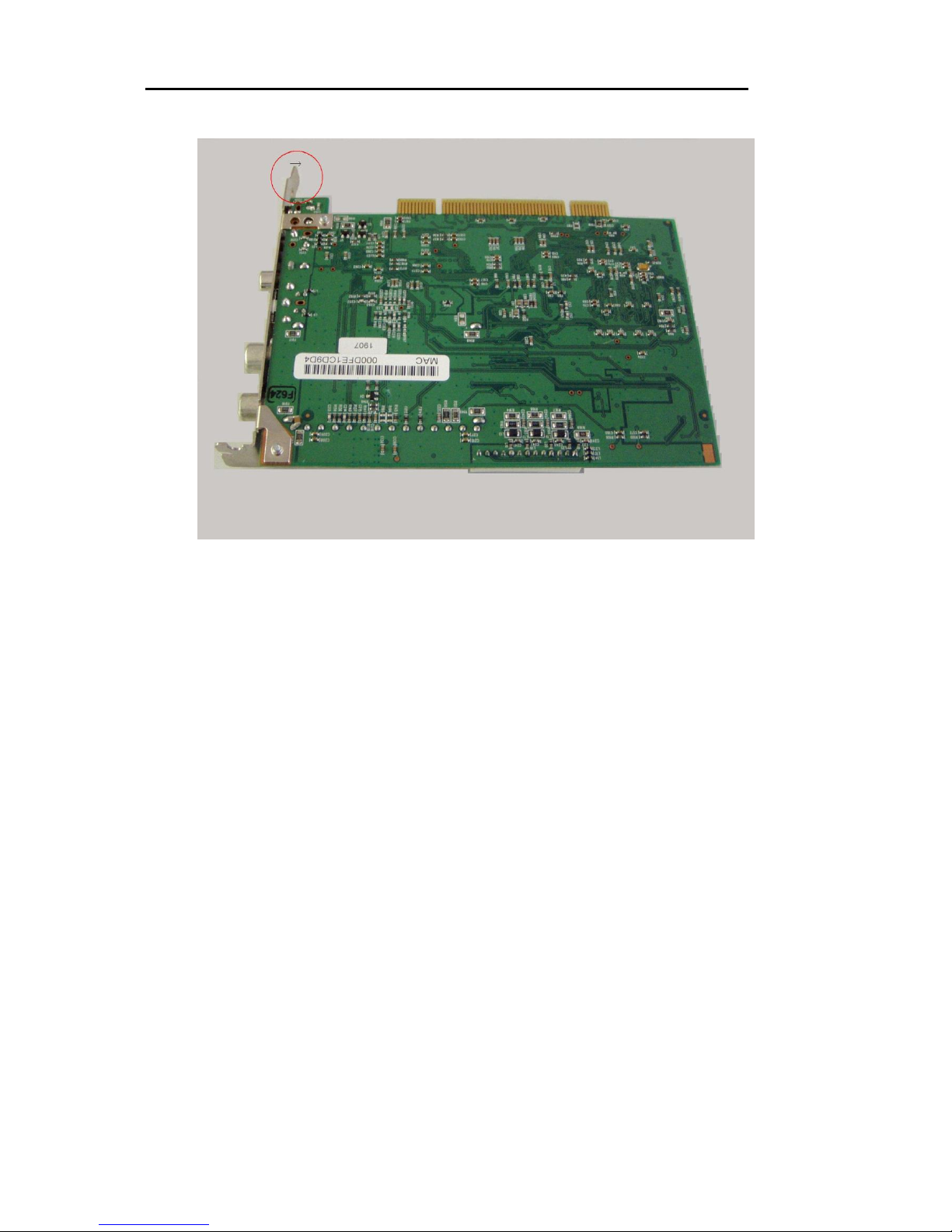
Attached to the internal cover plate, a PCI extender card is fitted as shown below
Figure 12: PCI riser
This is held in place by two screws. The completed assembly is inserted or removed vertically into the chassis as
shown below
Figure 13: Cover Assembly
Care should be taken when inserting the riser card into the on board socket to ensure that they align correctly
before fitting. The cover is held in place by three screws as shown above in Figure 13. There is a fourth screw
hole in the internal cover – this is only fitted AFTER the cover lid has been fitted
A PCI Adapter card is fitted by first removing the blank expansion bracket as follows

Scala L3 Installation
Page | 20
Figure 14:
When inserting a PCI Adapter, first loosen or remove the three screws retaining the internal cover plate. The
PCI Adapter can then be slid into place, again carefully aligning the edge connector of the card with the riser
slot.
Figure 15: Adapter bracket tail
The Internal cover plate has a small notch at its end to allow the Adapter bracket tail to pass through. If the
cover screws are fitted then this notch is too close to the front metalwork, forcing the Adapter tail to foul on the
EMC gasket for the motherboard as shown below.
Figure 16: Potential Foul
Scala L3 Installation
Page | 21
Before inserting a PCI card, slightly bend the end of the Adapter bracket as shown below.
Figure 17: PCI Card bracket
This also helps prevent the bracket fouling on the front EMC gasket.
Once the Adapter card is fitted, the three internal cover screws can be tightened so that the Adapter bracket tail
is locked in place. This helps prevent the Adapter from coming loose either in transit or during operation.

Scala L3 Installation
Page | 22
Optional Wi-Fi
The optional Wi-Fi card is attached to the underside of the internal cover as shown below
Figure 14: Optional Wi-Fi
The antenna is attached to the chassis as indicated in Figure 11. The Wi-Fi is a USB device and the motherboard
cable connects to the USB header on the motherboard as below
Figure 15: On-Board USB Header

Scala L3 BIOS Setup
Page | 23
Installing Operating Systems
Although the Scala Player chassis can accommodate a range of motherboards, specific Motherboards and
Graphics cards have been selected to provide a level of operation suitable for the Scala application software.
The Scala Player is supplied with a factory fitted Microsoft Windows XP Professional or XP Embedded
operating system, all the user needs to do is start the PC and complete the Microsoft mini-setup process
Contact Scala Support at http://support.scala.com/emea for help in configuring or using the software
applications.

Scala L3 BIOS Setup
Page | 24
BIOS Setup
To enter the BIOS Setup pages, press <DEL> during Power-On-Self-Test (POST).
If you have made any changes to the BIOS Setup which you think may be causing you problems, then when you
enter the BIOS Setup pages select LOAD Optimal Defaults to load the default BIOS settings.
If your’ BIOS needs to be updated for any reason, please contact Technical Support. Due to the danger of
damaging the system by trying to add the incorrect BIOS, any BIOS updates are not made available via the Blue
Chip driver website.
Please note that, the motherboard and BIOS used in the Scala L3, has more options and functionality than is
supported by the chassis
Main Menu
The main menu allows you to select from a list of setup functions together with two exit choices. Use the arrow
keys to select a specific item and press <Enter> to go to the sub-menu. Each item in the main menu is explained
below:
Standard CMOS Feature
This page displays the basic system configuration, such as system date, time and drive information. They all can
be viewed or set up through this menu.
Advanced BIOS Features
The advanced system features can be set up through this menu, including boot up settings and boot device
Priority.
Advanced Chipset Features
The menu offers settings to control Memory, Graphics and cache options.
Integrated Peripherals
All onboard peripherals can be set up through this menu. There are IDE devices, Super I/O devices such as
Serial I/O and other USB devices... etc.

Scala L3 BIOS Setup
Page | 25
Power Management Setup
All the items related with power saving function features can be set up through this menu.
Miscellaneous
This menu offers options to assign resources.
PC Health Status
This setup enables you to read temperatures and voltages of your CPU/System, as well as setup smart fan
operation and shutdown temperature if required
Thermal Throttling
This menu can set a temperature where CPU throttling can occur. This can be used to help prevent long term
damage if the system temperature gets too hot.
Power User
This menu allows VDIMM and NB voltage settings to be changed for overclocking – this is recommended to be
left as defaults
Password Settings
Supervisor and User passwords can be set if required
Load Fail-Safe/Optimal Defaults
These settings can be loaded through these two menu options.
Save & Exit Setup
Save setting values to CMOS and exit.
Exit Without Saving
Do not change anything and exit the setup.

Scala L3 BIOS Setup
Page | 26
CMOS Features
This sub-menu is used to set up the standard BIOS features, such as the date and time. Use the arrow up/down
keys to select an item, then use the <+> or <-> keys to change the setting.
Advanced BIOS Features

Scala L3 BIOS Setup
Page | 27
The important settings in this page are quick and quiet boot, as well as the Boot Order
When Enabled, Quick Power On Self Test allows BIOS to skip certain tests during POST to speed boot time
Advanced Chipset Features
Options include being able to enable the HDMI Audio and system cache. In the IGX Configuration sub menu,
the Internal Graphics mode etc can be set
Scala L3 BIOS Setup
Page | 28
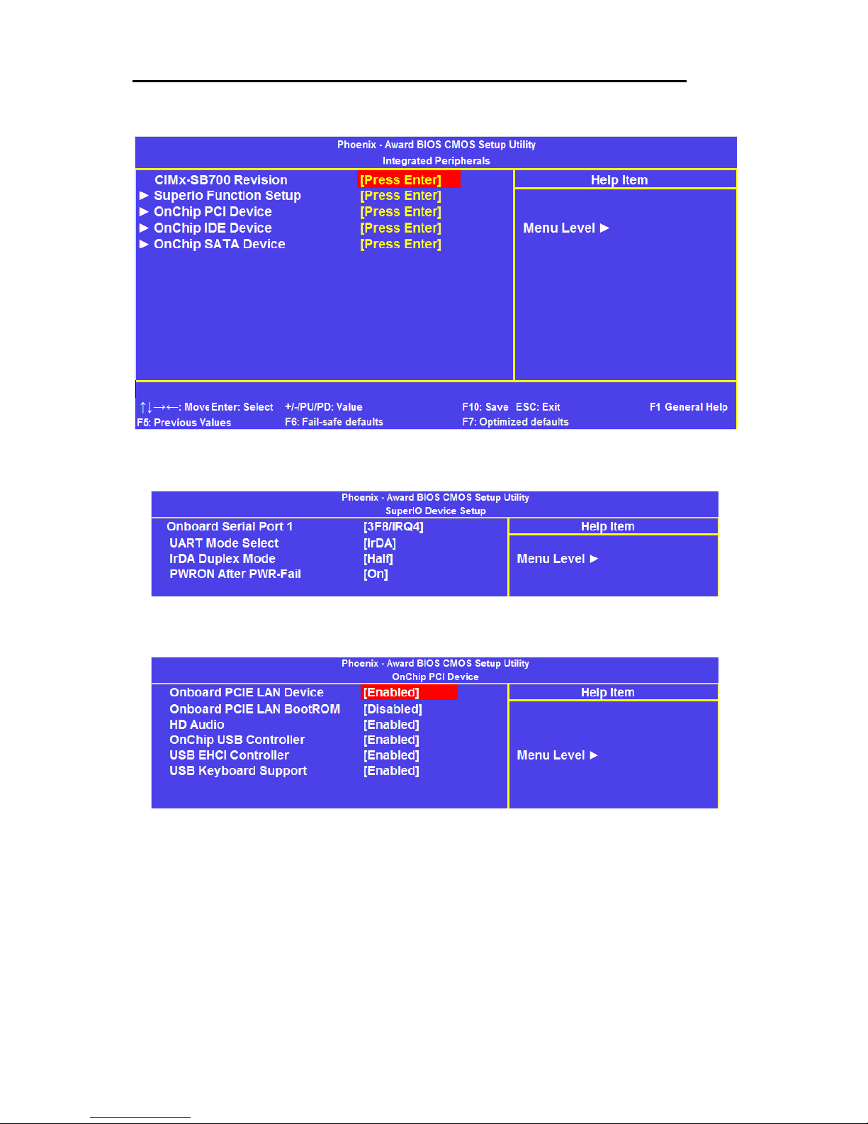
Integrated Peripherals
This Menu allows access to following sub-menus to setup Drive options, control USB settings, Serial Port
addressing
The Important setting in the Super IO page is Power On After power Fail. When set to ON, the unit will always
turn on when power is applied to the unit
The PCI Device settings page provides configuration options for USB, HD Audio and The on board LAN
devices, including LAN BootROM

Scala L3 BIOS Setup
Page | 29
The IDE Page provides options for how the IDE ports are configured. These will be configured at time of
manufacture and the user should not need to change any of these settings
The SATA devices page allows configuring how SATA devices are handled. Again, there is no need to change
these settings from default
Power Management Setup
This menu allows various options for controlling the power conditions of the Scala L3.
Wake On LAN functionality can be turned on by Enabling the Wake-up By PCI Card setting

Scala L3 BIOS Setup
Page | 30
Miscellaneous Control Configurations
As there is limited expansion options on the Scala L3, there should be no need to adjust any of these settings
PC Health Status
This menu displays temperature and voltage details which can be used to identify if the unit is operating out of
specification.
The Shutdown Temperature can be set to prevent damage to the CPU in the event of overheating.
The SMART FAN Function is used to control the speed of CPU FAN. At lower temperatures, this allows for
quieter operation.

Scala L3 BIOS Setup
Page | 31
Thermal Throttling
The Thermal Throttling page allows for the CPU to be put into throttling mode, if the temperature exceeds a set
value
This is useful in certain circumstances, however, if the CPU is reaching the throttling temperature, then it is an
indication that the Scala L3 is operating close to or above its upper temperature limit. Extended operation at
higher temperatures is not recommended.

Scala L3 Maintenance
Page | 32
Maintenance
On a regular basis the inside of the SCALA L3 should be cleaned out to prevent dust build up which could
eventually lead to obstruction of the convection airflow within the unit and prevent efficient operation.
Generally the enclosure design and the wiring layout will ensure that the cooling is stable. However, bear in
mind that any modifications to the installation may cause a restriction of the air vents.
After a period of several years, it may be necessary to replace the battery on the processor board, if it cannot
maintain the CMOS memory whilst the AC power is disconnected.
Replacing the Battery
The processor board includes a small 3V lithium battery (type CR-2032) to retain the BIOS settings in the
CMOS memory. Before attempting to replace the battery, please read the precautions detailed in the
introductory section. Remember that even discharged batteries can present a real personnel hazard if mistreated.
Do NOT under any circumstances try to remove the battery with metallic tools (pliers, tweezers etc.). They will
short out the battery with possible disastrous results.
Replace the battery by one of the same type, and that the clip is fully engaged. When the battery has been
replaced, the BIOS settings will revert to their default settings. Reset them as necessary to suit your application.
Fuses
There are no user-serviceable or replaceable fuses within the unit.

Scala L3 History
Page | 33
Amendment History
Issue Level
Issue Date
Author
Amendment Details
1.0
16-09-09
T Mck
First Release
Contact Details
Blue Chip Technology Ltd.
Chowley Oak
Tattenhall
Chester
CH3 9EX
U.K.
Telephone: +44 (0)1829 772000
Facsimile: +44 (0)1829 772001
www.bluechiptechnology.co.uk
Scala PC Sales
sales@bluechiptechnology.co.uk
Technical Support
http://support.scala.com/emea/
 Loading...