

Page 1
Manual 101010B02
Issue 11.02
Replaces 04.02
ZETA 2002
38 - 266 kW
Water chillers Air/water Axial fans and
self-contained scroll compressors
0062
Installation, operating,
and maintenance
manual
ISO 9001 - Cert. n. 0201
Page 2

Page 3

Blue Box
CONTENTS Page
ZETA 2002 - water chiller ......................................................................................................... 1
UNIT FRAME ............................................................................................................ 1
COMPRESSORS ........................................................................................................ 1
CONDENSER ............................................................................................................ 1
CONDENSER FANS................................................................................................... 1
EVAPORATOR .......................................................................................................... 1
REFRIGERANT CIRCUIT ............................................................................................. 1
ELECTRICAL PANEL .................................................................................................. 1
CONTROLS AND SAFETY DEVICES............................................................................ 2
TESTING .................................................................................................................. 2
ZETA UNIT VERSIONS .............................................................................................................. 2
ZETA 2002 /HP: reverse cycle heat pump................................................................... 2
ZETA 2002 LE: condensing unit. ................................................................................ 2
ZETA 2002 LE /HP: heat pump condensing unit .......................................................... 2
HYDRAULIC MODULE OPTIONS ............................................................................................... 3
ZETA 2002 /ST 2PS : ZETA 2002 /ST 2PS : unit with storage tank and pumps .............................. 3
ACCESSORY VERSIONS ........................................................................................................... 3
ZETA 2002 /DS: unit with desuperheaters................................................................... 3
ZETA 2002 /LN: low noise unit .................................................................................. 3
ZETA 2002 /SLN: extra low noise unit ........................................................................ 3
REFRIGERANT CIRCUIT ACCESSORIES: ..................................................................................... 4
- Step type condensing pressure contro ...................................................................... 4
- Condensing pressure control by means of fan speed regulator .................................. 4
- Dual set-point ........................................................................................................ 4
- Pressure gauges ..................................................................................................... 4
- Liquid receivers ..................................................................................................... 4
- Compressor suction and discharge valves ................................................................. 4
- Liquid line solenoid valve ........................................................................................ 4
HYDRAULIC CIRCUIT ACCESSORIES......................................................................................... 4
- Leaving water temperature control .......................................................................... 4
- Anti-freeze heater .................................................................................................. 4
- Water side relief valve (version ST only). .................................................................. 4
ELECTRICAL ACCESSORIES...................................................................................................... 4
- Serial interface ....................................................................................................... 4
- Power factor correction cos φ ≥ 0.9.......................................................................... 4
- Single voltage-free contacts for machine status signals .............................................. 4
- Set-point variable ................................................................................................... 4
- Remote user terminal panel .................................................................................... 4
VARIOUS ACCESSORIES........................................................................................................... 5
- Rubber antivibration mountings ............................................................................... 5
- Spring-type antivibration mounts.............................................................................. 5
- Timber packing crate.............................................................................................. 5
- Pallet/skid for shipment in a container...................................................................... 5
- Mesh coil guard with metallic filter .......................................................................... 5
- Anticorrosion treatment of coils for use in aggressive environments ............................ 5
- Non-standard RAL paint colours ............................................................................... 5
Page 4

Blue Box
SERIES ............................................................................................................................... 6
TECHNICAL DATA - R22........................................................................................... 7
TECHNICAL DATA - ELECTRICAL SPECIFICATIONS AND COMPONENTS R22 .......... 11
TECHNICAL DATA - ZETA 2002 /ST 2PS - R22 ........................................................... 13
TECHNICAL DATA - R407C ..................................................................................... 14
TECHNICAL DATA - ELECTRICAL SPECIFICATIONS AND COMPONENTS R407C.....18
TECHNICAL DATA - ZETA 2002 /ST 2PS - R407C ...................................................... 20
SOUND POWER AND PRESSURE LEVELS...................................................................21
FIELD OF APPLICATION ............................................................................................ 23
1. INTRODUCTION ...................................................................................................... 23
2. INSPECTION, TRANSPORT, SITE HANDLING..............................................................23
2.1 INSPECTION ...........................................................................................................23
2.2 LIFTING AND SITE HANDLING ..................................................................................23
2.3 UNPACKING ...........................................................................................................24
3. SAFETY PRECAUTIONS............................................................................................25
3.1 DEFINITION OF DANGER ZONE.................................................................................25
3.2 SAFETY PRESCRIPTIONS .......................................................................................... 25
MECHANICAL HAZARDS .................................................................................... 26
THERMAL HAZARDS........................................................................................... 27
NOISE-RELATED HAZARDS ..................................................................................28
ELECTRICAL HAZARDS .......................................................................................28
R407C REFRIGERANT SAFETY SHEETS .................................................................. 29
R22 REFRIGERANT SAFETY SHEETS....................................................................... 31
3.3 POSITIONING ..........................................................................................................33
4. INSTALLATION ........................................................................................................ 34
4.1 INSTALLATION CLEARANCES ..................................................................................34
4.2 ANTI-VIBRATION ISOLATORS (option) ....................................................................... 35
4.2.1 Rubber Anti-Vibration Isolators ............................................................................. 35
4.2.2 Spring Anti-Vibration Isolators .............................................................................. 35
4.3 WATER PIPING CONNECTIONS ................................................................................ 36
RECOMMENDED HYDRAULIC CIRCUIT DIAGRAM FOR ZETA 2002 UNITS.............. 37
RECOMMENDED HYDR. CIRCUIT DIAGR. FOR MODELS ZETA 2002 / ST 2PS ......... 38
HYDRAULIC CIRCUIT DIAGRAM VERSION ST /2PS................................................39
4.4 EVAPORATOR WATER PIPE CONNECTIONS .............................................................. 40
4.5 WATER FLOW SWITCH INSTALLATION INSTRUCTIONS (models 3.2 to 13.2) .............. 41
4.6 DESUPERHEATER HYDRAULIC CONNECTION (optional) ............................................ 43
4.7 ZETA 2002/DC HEAT RECOVERY EXCHANGER HYDRAULIC CONNECTIONS ..............43
DIAGRAM WITH 3-WAY VALVE ...........................................................................43
DIAGRAM WITH CONDENSING PRESSURE CONTROL VALVE................................. 44
4.8 PRESSURE RELIEF VALVES........................................................................................ 44
4.9 CONNECTIONS FOR VERSION /LE (MOTOCONDENSING UNIT) .................................. 45
4.9.1 Procedures to follow when sizing refrigerant lines ..................................................45
4.9.2 Evaporating section at lower level than condensing section .................................... 45
4.9.3 Evaporating section positioned higher than the condensing unit section................... 46
TABLE 1 - EXTERNAL PIPE DIAMENTERS FOR /LE VERSIONS .................................46
4.10 WATER FLOW RATE TO EVAPORATOR...................................................................... 47
4.11 CHILLER WATER TEMPERATURE (SUMMER CYCLE)..................................................47
4.12 HOT WATER TEMPERATURE (WINTER CYCLE) ..........................................................47
4.13 AMBIENT TEMPERATURE ........................................................................................47
4.14 FAN SPEED CONTROL (OPTIONAL)...........................................................................47
Page 5

Blue Box
4.15 OPERATION WITH LOW TEMPERATURE CHILLED WATER AT EVAPORATOR ............... 48
TABLE 2 - FREEZING POINT FOR WATER-ANTIFREEZE MIXTURES ........................... 48
OPERATING LIMITS - R22 refrigerant .................................................................... 49
OPERATING LIMITS - R407C refrigerant ................................................................ 51
EVAPORATOR PRESSURE DROP ........................................................................... 53
PUMPS AVAILABLE PRESSURE - MODEL ZETA 2002 /ST 2PS ................................ 54
4.16 ELECTRICAL CONNECTIONS .................................................................................... 55
4.16.1 General ........................................................................................................... 55
4.16.2 Power supply to crankcase heaters ....................................................................... 56
4.16.3 Potential free contacts ......................................................................................... 56
4.16.4 Flow switch electrical connections ........................................................................ 56
4.16.5 Circulating pump electrical connections ................................................................ 56
4.17 MICROPROCESSOR CONTROLLERS...........................................................................56
4.17.1 Microprocessor controller for /LE and HP/LE versions .............................................. 57
4.17.2 RS485 serial interface (optional) ........................................................................... 57
ELECTRICAL PANEL LAY OUT .................................................................................. 58
5. START-UP ........................................................................................................... 60
5.1 PRELIMINARY CHECKS............................................................................................60
6 UNITS WITH µCHILLER MICROPROCESSOR (models from 3.2 to 13.2)......................... 61
6.1 INTRODUCTION ...................................................................................................... 61
6.1.1 Display ........................................................................................................... 61
6.1.2 Machine status information.................................................................................. 61
6.1.3 Keypad ........................................................................................................... 61
6.1.4 Controls and display screens ................................................................................ 62
6.1.5 Muting the BUZZER.............................................................................................62
6.1.6 ALARMS reset .................................................................................................... 62
6.1.7 Activation/deactivation of COOLING operation (Summer mode) ............................. 63
6.1.8 Activation/deactivation of HEATING mode (winter mode) ...................................... 63
6.1.9 Switching off the machine (stand by)....................................................................63
6.1.10 Inlet water temperature control ............................................................................ 64
6.1.11 Defrosting (heat pump mode only) ....................................................................... 64
6.2 STARTING THE UNIT ............................................................................................... 66
6.3 STOPPING THE UNIT ............................................................................................... 66
6.3.1 Temporary stop...................................................................................................66
6.3.2 Seasonal stop ..................................................................................................... 67
6.4 EMERGENCY STOP ................................................................................................. 67
7. TROUBLESHOOTING ................................................................................................ 67
8 UNIT WITH pCO2 MICROPROCESSOR (models from 14.4 to 26.4) ............................... 75
8.1 INTRODUCTION ...................................................................................................... 75
8.1.1 Display ........................................................................................................... 75
8.1.2 Keypad ........................................................................................................... 75
8.2 OPERATING DESCRIPTION ....................................................................................... 77
8.2.1 Introduction ........................................................................................................ 77
8.2.2 Unit in stand-by mode ......................................................................................... 77
8.2.3 Enabling the unit................................................................................................. 77
8.2.4 Pumps management (ST units only)...................................................................... 77
8.2.5 Compressor start up ............................................................................................ 77
8.2.7 Heat pump mode operation.................................................................................78
8.2.8 Evaporator low temperature chilled water protection ............................................. 78
8.2.9 No-frost heater installed on the evaporator (optional)............................................. 78
8.2.10 Compressor operation ......................................................................................... 78
8.2.11 Compressors management .................................................................................. 79
8.2.12 High and low pressure alarms .............................................................................. 79
Page 6

Blue Box
8.2.13 Low ambient temp. kit (option - condensing control with fan speed regulator).........79
8.2.14 Changeover from chiller to heat pump and vice versa............................................ 79
8.2.15 Defrosting (heat pump mode operation only) ........................................................ 80
8.2.16 Total heat recovery (option) ................................................................................. 80
8.2.17 Dual set-point (option) ......................................................................................... 81
8.2.18 Operation leaving water temperature control (option) ............................................ 81
8.3 STARTING THE UNIT ...............................................................................................82
8.4 STOPPING THE UNIT ...............................................................................................82
8.4.1 Temporary stop...................................................................................................82
8.4.2 Seasonal stop .....................................................................................................82
8.5 EMERGENCY STOP ................................................................................................. 83
9. TROUBLESHOOTING ................................................................................................ 83
10. CHECKS DURING OPERATION..................................................................................91
10.1 INTRODUCTION ......................................................................................................91
10.1.1 Checking the refrigerant charge ...........................................................................91
11. CALIBRATION OF CONTROL EQUIPMENT ..................................................................92
11.1 INTRODUCTION ......................................................................................................92
TABLE 3 - CALIBRATION OF CONTROL EQUIPMENT .............................................. 92
TABLE 4 - CALIBRATION OF SAFETY DEVICES ....................................................... 90
12. MAINTENANCE AND PERIODIC CHECKS .................................................................93
12.1 WARNINGS ........................................................................................................... 93
12.2 INTRODUCTION ......................................................................................................93
12.3 REPAIRING THE REFRIGERANT CIRCUIT .................................................................... 94
12.3.1 Leak test ...........................................................................................................94
12.3.2 High vacuum and dehydration of the refrigerant circuit .......................................... 94
12.3.3 Refrigerant charge............................................................................................... 95
12.4 ENVIRONMENTAL CONSIDERATIONS .......................................................................95
13. DECOMMISSIONING THE UNIT ................................................................................ 96
REFRIGERANT CIRCUIT ........................................................................................97
OVERALL DIMENSIONS, WEIGHTS AND HYDRAULIC CIRCUIT CONNECTIONS .......109
Page 7

Blue Box - 1
ZETA 2002 - water chiller
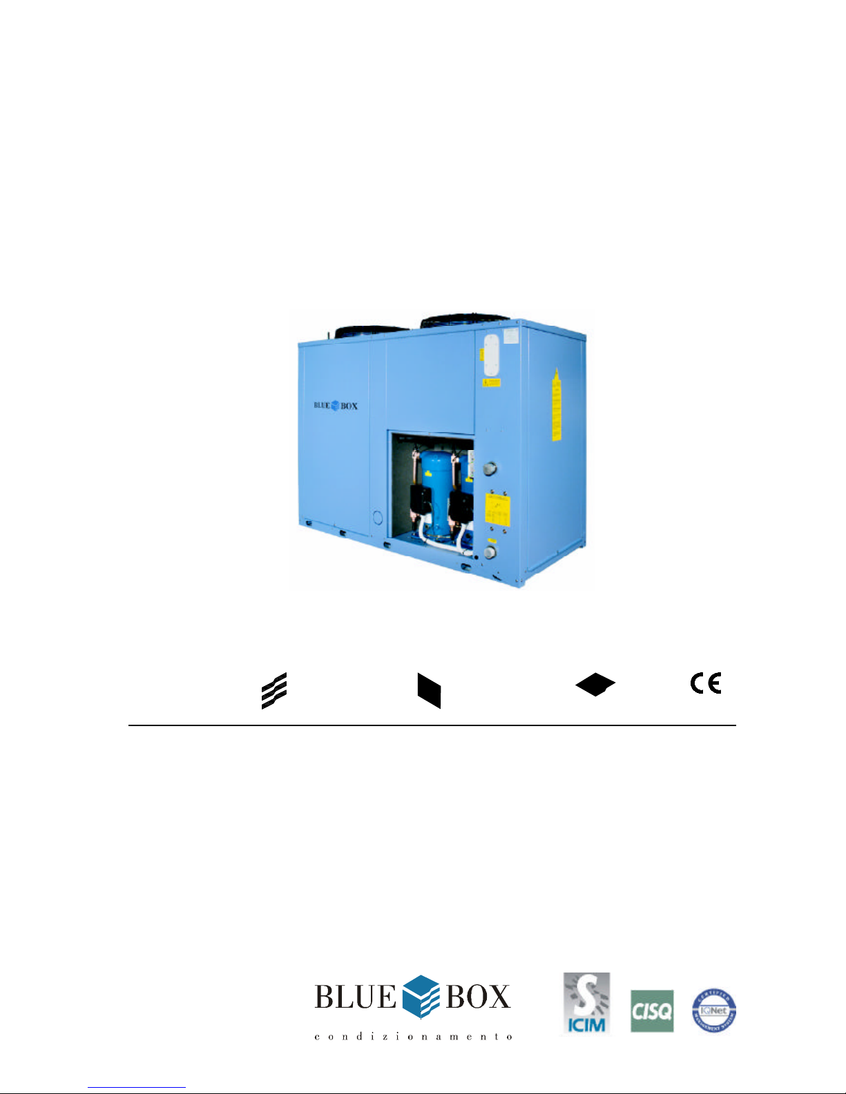
Air-cooled liquid chillers with hermetic scroll compressors and plate type evaporator, suitable for outdoor installations.
The unit has a refrigerant circuit for each pair of compressors.
UNIT FRAME
Self supporting frame with removable panels, internally coated with expanded polyurethane sound-absorbing
material; constructed from galvanized sheet steel with RAL 5014 powder paint baked at 180°C to provide a
durable weatherproof finish. Threaded fasteners in stainless steel.
COMPRESSORS
Hermetic scroll type with orbital motion, connected in tandem and equipped with oil level sight glass, Klixon
internal thermal protection and oil equalisation line.
The compressors are housed in a sound insulated compartment and separated from the air flow; access is
provided by removable panels which allow maintenance work to be performed in safety even when the unit is in
operation.
CONDENSER
Composed of a high efficiency coil manufactured from copper tubes and aluminium fins.
The finned coil is protected by a metal grille which is installed as standard.
CONDENSER FANS
Axial fans directly coupled to 6 pole motors with internal Klixon overload protection.
Motor protection category is IP 54. The fan is equipped with a safety grille to UNI EN 294.
EVAPORATOR
Brazed plate type in 316 AISI stainless steel. Thermal insulation of evaporator is provided by closed cell expanded
material. Each evaporator is equipped with a low water temperature probe for freeze protection and each unit is
equipped as standard with a mechanical flow switch.
REFRIGERANT CIRCUIT
Comprising: liquid valve, charge connection, liquid sight-glass, filter/dryer, thermostatic expansion valve with
external pressure equalisation, high and low pressure switches for 2-compressor models.
For 4-compressor models high and low pressure values and relative condensation and evaporation temperatures
are measured by pressure transducers that relay the signals to the controller so that they can be read directly on
the display. The high pressure side of the circuit is equipped with high pressure switches and relief valves.
ELECTRICAL PANEL
The electrical panel includes:
- main switch
- thermal magnetic circuit-breakers for fans and (if present) pumps; compressor fuses for the power circuit
- compressor contactors
- fan contactors
- pump contactors (ST version)
The microprocessor controls the following functions on all units:
- water temperature regulation
- freeze protection
- compressor time intervals
- compressor start sequence and automatic lead/lag selection
- alarm reset
- common alarm contact for remote signalling
- operating and alarm indicator LEDs
Page 8

Blue Box - 2
LCD display of the following information:
- water inlet and outlet temperature
- programmed temperature set-point and differential
- alarms description
- compressor hours run meter
for 4 compressor units:
- number of starts of the unit and the compressors
- high and low pressure values and relative condensation and evaporation temperature values.
Electrical power supply [V/f/Hz]: 400/3~/50 ±5%
CONTROLS AND SAFETY DEVICES
- chilled water temperature probe (at evaporator inlet)
- freeze protection probe at the outlet of each evaporator
- safety high pressure switch with manual reset
- low pressure switch (with manual reset controlled by the control)
- high pressure relief valve
- compressor over-temperature protection
- fan over-temperature protection
- mechanical flow switch, supplied as standard on all units, as kit for units 3.2 to 13.2 and factory installed for
units 14.4 to 26.4.
TESTING
The units are subjected to a dry run in the factory and supplied complete with oil and refrigerant.
ZETA UNIT VERSIONS
ZETA 2002 /HP: reverse cycle heat pump
The heat pump version operates as a air cooled chiller in summer and a air to water heat pump in winter by
reversing the refrigerant flow to suit the required operating mode.
- Refrigerant circuit:
4-way reversing valve, liquid receiver, second thermostatic valve.
- Electrical panel:
Microprocessor enabled for summer/winter changeover and automatic defrosting.
ZETA 2002 LE: condensing unit.
The basic ZETA 2002 model is not equipped with an evaporator or thermostatic valve.
Also the four compressor models are not supplied with a microprocessor controller. Liquid receivers can be
supplied as an accessory. The solenoid valve on the liquid line is supplied as standard.
ZETA 2002 LE /HP: heat pump condensing unit.
The basic ZETA 2002/HP model is not equipped with an evaporator, a thermostatic valve and four compressor
models are not supplied with a microprocessor controller. Liquid receivers can be supplied as an accessory. The
solenoid valve on the liquid line is supplied as standard.
Page 9

Blue Box - 3
ACCESSORY VERSIONS
ZETA 2002 /DC: unit with heat recovery condenser.
Not available for HP versions.
This accessory is available for the following models: 3.2-13.2 “1p-2p” 18.4-26.4”s”.
In addition to the components of version ZETA 2002, this unit includes a 100% heat recovery condenser for the
production of hot water, a recovery water temperature control thermostat, and a recovery circuit safety pressure
switch.
ZETA 2002 /DS: unit with desuperheaters
The brazed plate type desuperheater is arranged in series with the condensing coil. It is available for the following
models: from 3.2 to 13.2 with “1p-2p” and from 14.4 to 26.4 “1p-2p-1ps-2ps-s”.
It is also available in the HP configuration. In this case the installation must be fitted with a shut-off valve on the
water recovery circuit, to be closed during heat pump mode operation as described in the manual.
ZETA 2002 /LN: low noise unit
In addition to the components of version ZETA 2002, this unit includes:
galvanised sheet steel compressor compartment with full sound insulation using expanded polyurethane sound
absorption material and expanded polyurethane with an intermediate layer of high acoustic impedance material
applied to the sides of the compartment.
ZETA 2002 /SLN: extra low noise unit
In addition to the components of version LN, this unit is designed to operate with a slower fan speed to further
reduce noise levels.
HYDRAULIC MODULE OPTIONS
ZETA 2002 /ST 2PS : unit with storage tank and pumps.
In addition to the components of version ZETA 2002, this unit includes:
insulated storage tank; run and standby circulating pumps, with automatic changeover for four compressor models
and manual changeover for two compressor models;
Also provided are an expansion tank, check valves and gate valves.
Version ST is available in the following additional four configurations:
- ST 1PS: with 1 pump and tank;
- ST 2P : with 2 pumps and no tank;
- ST S : with tank and no pumps;
- ST 1P : with 1 pump and no tank.
Page 10

Blue Box - 4
REFRIGERANT CIRCUIT ACCESSORIES:
- Step type condensing pressure control
(ambient air minimum temperature 0 °C).
The control is managed in On/Off mode by the microprocessor by means of the pressure transducers.
Available for models 18.4 to 26.4 only.
- Condensing pressure control by fan speed regulator
(ambient air minimum temperature -20 °C).
Fan speed is regulated in accordance with the condensation pressure read by the pressure transducers.
Available for all models.
- Dual set-point.
With double thermostatic valves + solenoid valves. In units with two compressors the set-point must be
modified manually on the controller. For four compressor units two set-points can be programmed and
switched between them from the keypad or using a digital input. The type of selection must be specified at
the time of the order. In all cases the thermostatic valves switch automatically on the basis of the water temperature.
- Pressure gauges.
Available for all models. Note however that on 4-compressor units the suction and discharge pressure values
are read by transducers that relay the results to the controller display.
- Liquid receivers
(standard on versions /HP and /HP/LE)
- Compressor suction and discharge valves
- Liquid line solenoid valve
.
HYDRAULIC CIRCUIT ACCESSORIES
- Leaving water temperature control.
Available only on 4-compressor models (not HP versions).
- Anti-freeze heater
- Water side relief valve (version ST only).
The value is set at 6 bar, corresponding to the maximum permissible working pressure.
ELECTRICAL ACCESSORIES
- Serial interface:
- 2-compressor units are equipped with RS485 type serial interface with Carel protocol.
- 4-compressor units are equipped with RS485 type serial interface with Modbus protocol; the following
optional protocols are available on request: Carel; Echelon in version RS485 or in version FTT10
- Power factor correction cos φ ≥ 0.9 at nominal operating conditions
- Single voltage-free contacts for machine status signals
- Set-point variable in a range of 3 °C with remote signal (0-1V, 0-10V, 0-4mA, 0-20mA).
Available only for models from 16.4 to 26.4
- Remote user terminal panel (in addition to the standard terminal)
Page 11

Blue Box - 5
VARIOUS ACCESSORIES
- Rubber anti-vibration mountings.
Available for all models in the series
- Spring type anti-vibration mounts.
Available for models 18.4 to 26.4
- Timber crate packing
- Pallet/skid for container shipment
- Mesh coil guard with metallic filter.
Standard equipment on models from 14.4 to 26.4.
- Anti-corrosion treatment of coils for use in aggressive environments
- Non-standard RAL paint colours
Page 12
Blue Box - 6
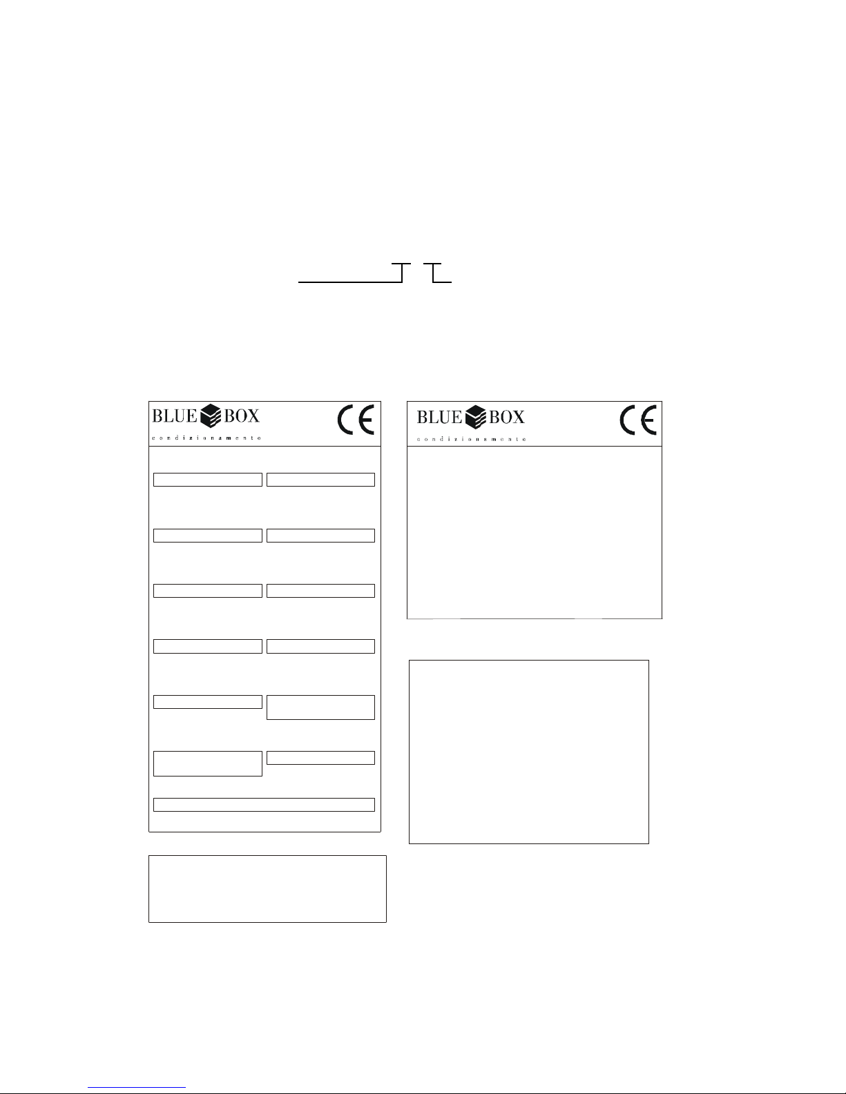
The model, serial number, characteristics, power supply, etc. are shown by means of decals on the unit.
SERIES
The ZETA 2002 series of water cooled chillers and heat pumps, are available in various sizes with capacities from
38 to 266 kW.
Model designations consist of two numbers:
SERIAL NO. - SERIENUMMER
MATRICOLA - MATRICULE
Corrente massima di spunto
Max starting current
Max. Anlaufstrom
Courant maxi démarrage
Tipo refrigerante
Refrigerant type
Kältemittel Typ
Type de refrigerant
Numero circuiti refrigerante
Refrigerant circuit number
Anzahl des Kältemittelkreislaufes
Numero circuits refrigerant
Press. massima circuito idraulico
Max. Hydraultic circuit pressure
Max. Druck im Hydraul. Kreislauf
Pression maxi circuit hydraulique
Data di produzione
Manufacturing date
Erstellungsdatum
Date de fabrication
Press. massima circuito refriger.
Max. Refrigerant circuit pressure
Max. Druck Kältekreislauf
Pression maxi circuit refrigerant
IP quadro elettrico
IP electrical board
IP E-Schrank
IP tableau electrique
Tensione circuiti ausiliari
Auxiliary circuit voltage
Steuerspannung
Tension circuits auxiliares
Matricola/Serial number
(BBOX) Matrikel/Matricule
Corrente massima assorbita
Max absorbed current
Maximalstromverbrauch
Courant maxi absorbée
Modello/Model
Modell/Modèle
Tensione-Fasi-Frequenza
Voltage-Phasses-Frequency
Spannung-Phasses-Frequenz
Tension-Phasses-Fréquence
Buono di Produzione
A A
kPa
MODELLO MODELE
MODEL -TYP
kPa
Carica refrigerante per circuito(kg)/Refrigerant charge per circuit
Kältemittelfüllung KreislaufCharge de refigerant chaque circuit
(kg)
/(kg)/(kg)
C2
C1
C3
C4
REFRIGERANTE - REFRIGERANT - KÄLTEMITTEL - REFRIGERANT
MATRICOLA - MATRICULE - SERIAL NO. - SERIENUMMER
MODELLO - MODELE - MODEL - TYP
REFRIGERANTE - REFRIGERANT - KÄLTEMITTEL - REFRIGERANT
MATRICOLA - MATRICULE - SERIAL NO. - SERIENUMMER
MODELLO - MODELE - MODEL - TYP
Buono di Produzione
bar
bar
0062
0062
0062
Via Enrico Mattei, 20
35028 Piove di Sacco (PD)
ITALY
Tel. +039.049.9716300
Via Enrico Mattei, 20
35028 Piove di Sacco (PD)
ITALY
Tel. +039.049.9716300
Via Enrico Mattei, 20
35028 Piove di Sacco (PD)
ITALY
Tel. +039.049.9716300
REFRIGERANTE
MATRICOLA
MODELLO
ESECUZIONE SECONDO
NORMATIVE
SCHEMA ELETTRICO
SCHEMA FRIGORIFERO
SCHEMA IDRAULICO
DISEGNO MECCANICO
number of compressors
ZETA 2002 14.4
Shows the model
Page 13
Blue Box - 7
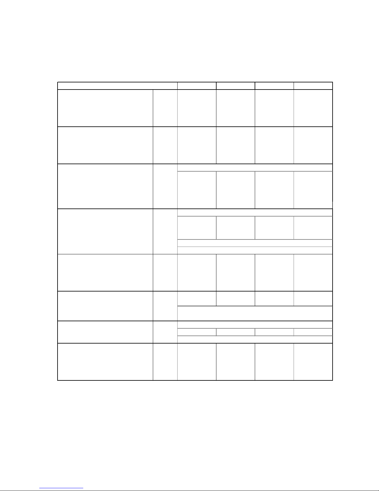
TECHNICAL DATA
R22 refrigerant
(*) ambient air temperature 35°C; evaporator entering/leaving water temperature 12-7 °C;.
(**) ambient air temperature 8°C DB, 70%RH; condenser entering/leaving water temperature 40-45 °C.
MODEL ZETA 2002 3.2 4.2 5.2 6.2
Cooling (*)
Nominal capacity kW 38,4 47,1 52,9 61,6
Evaporator water flow l/s 1,835 2,251 2,528 2,943
l/h 6.607 8.105 9.102 10.596
Evaporator pressure drop kPa 59,1 59,2 46,9 51,5
Heating (**)
Nominal capacity kW 38,4 46,9 53,2 60,8
Condenser water flow l/s 1,833 2,239 2,540 2,907
l/h 6.600 8.061 9.146 10.466
Condenser pressure drop kPa 59 58,6 47,3 50,3
Compressors type
Quantity n 2 2 2 2
Refrigerant circuits n 1 1 1 1
Absorbed power cooling (*) kW 12 14,3 16,5 18,7
Absorbed power heating (**) kW 12,8 15,4 16,9 19,5
Capacity steps % 0/50/100 0/50/100 0/50/100 0/50/100
Condenser cooling fans type
Total air flow m3/s 4,472 4,472 4,472 4,528
m3/h 16.100 16.100 16.100 16.300
Fan motor power n x kW 2 x 0,6 2 x 0,6 2 x 0,6 2 x 0,6
Nominal revolution speed RPM
Electric motor supply V/Ph/Hz
Refrigerant charge
Chiller version kg 1 x 14,5 1 x 14,5 1 x 14,5 1 x 19,5
Heat pump version kg 1 x 15 1 x 15 1 x 15 1 x 22
Oil
Oil charge l 2 x 3,3 2 x 3,3 2 x 3,8 1 x 4 + 1 x 3,8
Oil producer
Oil type
Evaporator type
Heat exchanger water volume l 4,6 5,7 7,4 8,4
Max operating pressure water side bar
Dimension and weight
Length mm 2.233 2.233 2.233 2.233
Width mm 1.043 1.043 1.043 1.043
Heigth mm 1.740 1.740 1.740 1.740
Shipping weight kg 594 604 625 672
scroll
860
30
Maneurop
160 P
axial
230/~/50
plate
Page 14
Blue Box - 8
TECHNICAL DATA
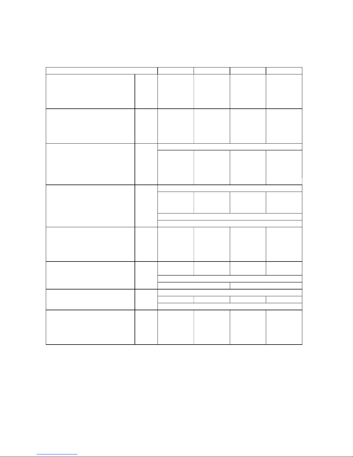
R22 refrigerant
(*) ambient air temperature 35°C; evaporator entering/leaving water temperature 12-7 °C;.
(**) ambient air temperature 8°C DB, 70%RH; condenser entering/leaving water temperature 40-45 °C.
MODEL ZETA 2002 7.2 8.2 9.2 10.2
Cooling (*)
Nominal capacity kW 68,9 78,9 93,4 105,4
Evaporator water flow l/s 3,292 3,771 4,460 5,034
l/h 11.852 13.577 16.057 18.121
Evaporator pressure drop kPa 43,8 45,2 47,9 45,6
Heating (**)
Nominal capacity kW 68,5 79,7 92,6 105,6
Condenser water flow l/s 3,274 3,807 4,425 5,044
l/h 11.787 13.704 15.931 18.158
Condenser pressure drop kPa 43,3 46 47,2 45,8
Compressors type
Quantity n 2 2 2 2
Refrigerant circuits n 1 1 1 1
Absorbed power cooling (*) kW 21,7 25 29,7 35,7
Absorbed power heating (**) kW 22,1 25,5 29,8 34,1
Capacity steps % 0/50/100 0/50/100 0/50/100 0/50/100
Condenser cooling fans type
Total air flow m3/s 4,528 4,389 6,833 6,833
m3/h 16.300 15.800 24.600 24.600
Fan motor power n x kW 2 x 0,6 2 x 0,6 3 x 0,6 3 x 0,6
Nominal revolution speed RPM
Electric motor supply V/Ph/Hz
Refrigerant charge
Chiller version kg 1 x 19,5 1 x 22 1 x 27,5 1 x 27,5
Heat pump version kg 1 x 22 1 x 27 1 x 32 1 x 32
Oil
Oil charge l 2 x 4 2 x 6,6 1 x 8 + 1 x 6,6 2 x 8
Oil producer
Oil type
Evaporator type
Heat exchanger water volume l 4,2 4,8 6,3 7,3
Max operating pressure water side bar
Dimension and weight
Length mm 2.233 2.233 3.234 3.234
Width mm 1.043 1.043 1.144 1.144
Heigth mm 1.740 1.740 1.740 1.740
Shipping weight kg 690 737 981 1.058
230/~/50
160 P 320 SZ
plate
30
scroll
axial
860
Maneurop
Page 15
Blue Box - 9
TECHNICAL DATA
R22 refrigerant
(*) ambient air temperature 35°C; evaporator entering/leaving water temperature 12-7 °C;.
(**) ambient air temperature 8°C DB, 70%RH; condenser entering/leaving water temperature 40-45 °C.
MODEL ZETA 2002 12.2 13.2 14.4 16.4
Cooling (*)
Nominal capacity kW 120,4 130,3 139,4 159,6
Evaporator water flow l/s 5,754 6,225 6,659 7,626
l/h 20.715 22.409 23.974 27.453
Evaporator pressure drop kPa 50,9 44 51,6 55,1
Heating (**)
Nominal capacity kW 118,4 131,2 137,1 159,4
Condenser water flow l/s 5,656 6,268 6,548 7,614
l/h 20.362 22.566 23.573 27.409
Condenser pressure drop kPa 49,2 44,6 50 55
Compressors type
Quantity n 2 2 4 4
Refrigerant circuits n 1 1 2 2
Absorbed power cooling (*) kW 38,1 43,6 42,6 49
Absorbed power heating (**) kW 37,7 41,3 44,1 51
Capacity steps % 0/50/100 0/50/100 0/25/50/75/100 0/25/50/75/100
Condenser cooling fans type
Total air flow m3/s 6,600 6,583 11,267 11,267
m3/h 23.760 23.700 40.560 40.560
Fan motor power n x kW 3 x 0,6 3 x 0,6 2 x 2,0 2 x 2,0
Nominal revolution speed RPM
Electric motor supply V/Ph/Hz
Refrigerant charge
Chiller version kg 1 x 32 1 x 32 2 x 19,5 2 x 21
Heat pump version kg 1 x 36 1 x 36 2 x 22 2 x 23
Oil
Oil charge l 2 x 8 2 x 8 4 x 4 4 x 6,6
Oil producer
Oil type
Evaporator type
Heat exchanger water volume l 8,4 9,4 5,2 4,8
Max operating pressure water side bar
Dimension and weight
Length mm 3.234 3.234 3.234 3.234
Width mm 1.144 1.144 1.119 1.119
Heigth mm 1.740 1.740 2.380 2.380
Shipping weight kg 1.124 1.158 1.400 1.464
230/~/50 400/3~/50
320 SZ 160 P
plate
30
axial
Maneurop
860
scroll
Page 16
Blue Box - 10
TECHNICAL DATA
R22 refrigerant
(*) ambient air temperature 35°C; evaporator entering/leaving water temperature 12-7 °C;.
(**) ambient air temperature 8°C DB, 70%RH; condenser entering/leaving water temperature 40-45 °C.
MODEL ZETA 2002 18.4 20.4 24.4 26.4
Cooling (*)
Nominal capacity kW 188,8 215,5 240,9 266,2
Evaporator water flow l/s 9,019 10,298 11,508 12,718
l/h 32.469 37.073 41.430 45.786
Evaporator pressure drop kPa 61,6 64 71,4 70,9
Heating (**)
Nominal capacity kW 185,2 211,1 236,8 262,4
Condenser water flow l/s 8,851 10,088 11,312 12,536
l/h 31.863 36.316 40.724 45.131
Condenser pressure drop kPa 59,4 61,6 69,1 68,9
Compressors type
Quantity n 4 4 4 4
Refrigerant circuits n 2 2 2 2
Absorbed power cooling (*) kW 58,2 68,7 76,3 83,9
Absorbed power heating (**) kW 59,6 68,2 75,4 82,7
Capacity steps % 0/25/50/75/100 0/25/50/75/100 0/25/50/75/100 0/25/50/75/100
Condenser cooling fans type
Total air flow m3/s 16,375 16,417 19,389 18,500
m3/h 58.950 59.100 69.800 66.600
Fan motor power n x kW 3 x 2,0 3 x 2,0 4 x 2,0 4 x 2,0
Nominal revolution speed RPM
Electric motor supply V/Ph/Hz
Refrigerant charge
Chiller version kg 2 x 27 2 x 27 2 x 26 2 x 31,5
Heat pump version kg 2 x 30
2 x 30
2 x 30 2 x 35
Oil
Oil charge l 2 x 8 + 2 x 6,6 4 x 8 4 x 8 4 x 8
Oil producer
Oil type
Evaporator type
Heat exchanger water volume l 6,3 7,3 8,4 9,4
Max operating pressure water side bar
Dimension and weight
Length mm 4.234 4.234 4.234 4.234
Width mm 1.119 1.119 1.119 1.119
Heigth mm 2.380 2.380 2.380 2.380
Shipping weight kg 1.930 2.089 2.208 2.349
plate
30
Maneurop
320 SZ
880
400/3~/50
axial
scroll
Page 17
Blue Box - 11
TECHNICAL DATA - ELECTRICAL CHARACTERISTICS AND COMPONENTS
R22 refrigerant
(1) mains power supply to allow unit operation.
(2) maximum current before safety cut-outs stop the unit. This value is never exceeded and must be used to size
the electrical supply cables and relevant safety devices (refer to electrical wiring diagram supplied with the unit).
All values in brackets are refer to /ST version (units with storage tank) or units with pump.
MODEL ZETA 2002 3.2 4.2 5.2 6.2
Maximum absorbed power
(1)
kW 17,6 19,6 24 27
kW (18,1) (20,1) (24,5) (28,1)
Maximum starting current A 120,4 155,4 150,4 205,4
A (122,1) (157,1) (152,1) (208,3)
Full load current
(2)
A 39,4 45,4 55,4 65,4
A (41,1) (47,1) (57,1) (68,3)
Fan motor nominal power n x kW 2 x 0,6 2 x 0,6 2 x 0,6 2 x 0,6
Fan motor nominal absorbed current n x A 2 x 2,7 2 x 2,7 2 x 2,7 2 x 2,7
Pump motor nominal power kW (1 x 0,5) (1 x 0,5) (1 x 0,5) (1 x 1,1)
Pump motor nominal absorbed power A (1 x 1,7) (1 x 1,7) (1 x 1,7) (1 x 2,9)
Power supply V/Ph/Hz
Control power supply V/Ph/Hz
Control circuit supply V/Ph/Hz
Condenser fans supply V/Ph/Hz
Pump supply, ST groups V/Ph/Hz
400V 3N ~ 50Hz ±5% V
230V/ ~/50Hz
24V/~/50Hz
230V/ ~/50Hz
400V/3~/50
MODEL ZETA 2002 7.2 8.2 9.2 10.2
Maximum absorbed power
(1)
kW 30 35,2 41,7 47,6
kW (31,1) (36,3) (43,2) (49,1)
Maximum starting current A 215,4 215,4 258,1 273,1
A (218,3) (218,3) (262,4) (277,4)
Full load current
(2)
A 75,4 75,4 93,1 108,1
A (78,3) (78,3) (97,4) (112,4)
Fan motor nominal power n x kW 2 x 0,6 2 x 0,6 3 x 0,6 3 x 0,6
Fan motor nominal absorbed current n x A 2 x 2,7 2 x 2,7 3 x 2,7 3 x 2,7
Pump motor nominal power kW (1 x 1,1) (1 x 1,1) (1 x 1,5) (1 x 1,5)
Pump motor nominal absorbed power A (1 x 2,9) (1 x 2,9) (1 x 4,3) (1 x 4,3)
Power supply V/Ph/Hz
Control power supply V/Ph/Hz
Control circuit supply V/Ph/Hz
Condenser fans supply V/Ph/Hz
Pump supply, ST groups V/Ph/Hz
24V/~/50Hz
400V 3N ~ 50Hz ±5% V
230V/ ~/50Hz
230V/ ~/50Hz
400V/3~/50
Page 18
Blue Box - 12
TECHNICAL DATA - ELECTRICAL CHARACTERISTICS AND COMPONENTS
R22 refrigerant
MODEL ZETA 2002 12.2 13.2 14.4 16.4
Maximum absorbed power
(1)
kW 52,4 57,2 61,6 72
kW (54,6) (59,4) (63,8) (74,2)
Maximum starting current A 328,1 347,1 288 288
A (333,4) (352,4) (293,3) (293,3)
Full load current
(2)
A 127,1 146,1 148 148
A (132,4) (151,4) (153,3) (153,3)
Fan motor nominal power n x kW 3 x 0,6 3 x 0,6 2 x 2,0 2 x 2,0
Fan motor nominal absorbed current n x A 3 x 2,7 3 x 2,7 2 x 4,0 2 x 4,0
Pump motor nominal power kW (1 x 2,2) (1 x 2,2) (1 x 2,2) (1 x 2,2)
Pump motor nominal absorbed power A (1 x 5,3) (1 x 5,3) (1 x 5,3) (1 x 5,3)
Power supply V/Ph/Hz
Control power supply V/Ph/Hz
Control circuit supply V/Ph/Hz
Condenser fans supply V/Ph/Hz
Pump supply, ST groups V/Ph/Hz 400V/3~/50
230V/ ~/50Hz 400V/3~/50
400V 3N ~ 50Hz ±5% V
230V/ ~/50Hz
24V/~/50Hz
MODEL ZETA 2002 18.4 20.4 24.4 26.4
Maximum absorbed power
(1)
kW 85,8 97,6 109,2 118,8
kW (89,8) (101,6) (113,2 (124,3)
Maximum starting current A 347 377 455 493
A (356,5) (386,5) (464,5) (505)
Full load current
(2)
A 182 212 254 292
A (191,5) (221,5) (263,5) (304)
Fan motor nominal power n x kW 3 x 2,0 3 x 2,0 4 x 2,0 4 x 2,0
Fan motor nominal absorbed current n x A 3 x 4,0 3 x 4,0 4 x 4,0 4 x 4,0
Pump motor nominal power kW (1 x 4,0) (1 x 4,0) (1 x 4,0) (1 x 5,5)
Pump motor nominal absorbed power A (1 x 9,5) (1 x 9,5) (1 x 9,5) (1 x 12,0)
Power supply V/Ph/Hz
Control power supply V/Ph/Hz
Control circuit supply V/Ph/Hz
Condenser fans supply V/Ph/Hz
Pump supply, ST groups V/Ph/Hz 400V/3~/50
400V/3~/50
24V ~ 50Hz
400V 3N ~ 50Hz ±5% V
230/~/50
(1) mains power supply to allow unit operation.
(2) maximum current before safety cut-outs stop the unit. This value is never exceeded and must be used to size
the electrical supply cables and relevant safety devices (refer to electrical wiring diagram supplied with the unit).
All values in brackets are refer to /ST version (units with storage tank) or units with pump.
Page 19
Blue Box - 13
TECHNICAL DATA - ZETA 2002 /ST 2PS
R22 refrigerant
MODEL ZETA 2002 3.2 4.2 5.2 6.2
Pump section
Evaporator water flow l/s 1,84 2,25 2,53 2,94
l/h 6.607 8.105 9.102 10.596
Pump nominal power kW 0,5 0,5 0,5 1,1
External available pressure kPa 114 95 93 139
Storage tank water volume l 200 200 200 200
Dimension and weight
Length mm 2.233 2.233 2.233 2.233
Width mm 1.043 1.043 1.043 1.043
Heigth mm 1.740 1.740 1.740 1.740
Shipping weight kg 724 734 755 807
MODEL ZETA 2002 7.2 8.2 9.2 10.2
Pump section
Evaporator water flow l/s 3,29 3,77 4,46 5,03
l/h 11.852 13.577 16.057 18.121
Pump nominal power kW 1,1 1,1 1,5 1,5
External available pressure kPa 134 113 122 107
Storage tank water volume l 200 200 450 450
Dimension and weight
Length mm 2.233 2.233 3.234 3.234
Width mm 1.043 1.043 1.144 1.144
Heigth mm 1.740 1.740 1.740 1.740
Shipping weight kg 825 868 1.142 1.219
MODEL ZETA 2002 12.2 13.2 14.4 16.4
Pump section
Evaporator water flow l/s 5,75 6,23 6,66 7,63
l/h 20.715 22.409 23.974 27.453
Pump nominal power kW 2,2 2,2 2,2 2,2
External available pressure kPa 114 108 134 98
Storage tank water volume l 450 450 340 340
Dimension and weight
Length mm 3.234 3.234 3.234 3.234
Width mm 1.144 1.144 1.119 1.119
Heigth mm 1.740 1.740 2.380 2.380
Shipping weight kg 1.275 1.309 1.642 1.678
MODEL ZETA 2002 18.4 20.4 24.4 26.4
Pump section
Evaporator water flow l/s 9,02 10,30 11,51 12,72
l/h 32.469 37.073 41.430 45.786
Pump nominal power kW 4 4 4 5,5
External available pressure kPa 139 123 100 159
Storage tank water volume l 700 700 700 700
Dimension and weight
Length mm 5.234 5.234 5.234 5.234
Width mm 1.119 1.119 1.119 1.119
Heigth mm 2.380 2.380 2.380 2.380
Shipping weight kg 2.290 2.449 2.622 2.749
Page 20
Blue Box - 14
TECHNICAL DATA
R407C refrigerant
(*) ambient air temperature 35°C; evaporator entering/leaving water temperature 12-7 °C;.
(**) ambient air temperature 8°C DB, 70%RH; condenser entering/leaving water temperature 40-45 °C.
MODEL ZETA 2002 3.2 4.2 5.2 6.2
Cooling (*)
Nominal capacity kW 37,1 44,7 51,4 60,3
Evaporator water flow l/s 1,77 2,13 2,45 2,88
l/h 6.377 7.682 8.833 10.379
Evaporator pressure drop kPa 57,2 55,4 45,9 51,4
Heating (**)
Nominal capacity kW 36,4 44,8 51,9 60
Condenser water flow l/s 1,74 2,14 2,48 2,87
l/h 6.267 7.698 8.923 10.318
Condenser pressure drop kPa 55,3 55,6 46,8 50,8
Compressors type
Quantity n 2 2 2 2
Refrigerant circuits n 1 1 1 1
Absorbed power cooling (*) kW 12,3 14,8 17,5 19,7
Absorbed power heating (**) kW 12,7 15,9 18,4 20,9
Capacity steps % 0-50-100 0-50-100 0-50-100 0-50-100
Condenser cooling fans type
Total air flow m3/s 4,47 4,47 4,47 4,53
m3/h 16.100 16.100 16.100 16.300
Fan motor power n x kW 2 x 0,6 2 x 0,6 2 x 0,6 2 x 0,6
Nominal revolution speed RPM
Electric motor supply V/Ph/Hz
Refrigerant charge
Chiller version kg 1 x 14,5 1 x 14,5 1 x 14,5 1 x 19,5
Heat pump version kg 1 x 15 1 x 15 1 x 15 1 x 22
Oil
Oil charge l 2 x 3,3 2 x 3,3 2 x 3,8 1 x 4 + 1 x 3,8
Oil producer
Oil type
Evaporator type
Heat exchanger water volume l 4,6 5,7 7,4 8,4
Max operating pressure water side bar
Dimension and weight
Length mm 2.233 2.233 2.233 2.233
Width mm 1.043 1.043 1.043 1.043
Heigth mm 1.740 1.740 1.740 1.740
Shipping weight kg 594 604 625 672
230/~/50
plate
30
scroll
860
Maneurop
160 SZ
axial
Page 21
Blue Box - 15
TECHNICAL DATA
R407C refrigerant
(*) ambient air temperature 35°C; evaporator entering/leaving water temperature 12-7 °C;.
(**) ambient air temperature 8°C DB, 70%RH; condenser entering/leaving water temperature 40-45 °C.
MODEL ZETA 2002 7.2 8.2 9.2 10.2
Cooling (*)
Nominal capacity kW 67,5 77,6 91,6 102,4
Evaporator water flow l/s 3,23 3,71 4,37 4,89
l/h 11.608 13.347 15.748 17.611
Evaporator pressure drop kPa 43,7 45,4 47,9 44,8
Heating (**)
Nominal capacity kW 68,1 78,7 92,7 106,6
Condenser water flow l/s 3,25 3,76 4,43 5,10
l/h 11.712 13.530 15.937 18.343
Condenser pressure drop kPa 44,4 46,5 49 48,4
Compressors type
Quantity n 2 2 2 2
Refrigerant circuits n 1 1 1 1
Absorbed power cooling (*) kW 22,7 26,6 31,3 37,6
Absorbed power heating (**) kW 23,4 27,5 32,1 36,7
Capacity steps % 0-50-100 0-50-100 0-50-100 0-50-100
Condenser cooling fans type
Total air flow m3/s 4,53 4,39 6,83 6,83
m3/h 16.300 15.800 24.600 24.600
Fan motor power n x kW 2 x 0,6 2 x 0,6 3 x 0,6 3 x 0,6
Nominal revolution speed RPM
Electric motor supply V/Ph/Hz
Refrigerant charge
Chiller version kg 1 x 19,5 1 x 22 1 x 27,5 1 x 27,5
Heat pump version kg 1 x 22 1 x 27 1 x 32 1 x 32
Oil
Oil charge l 2 x 4 2 x 6,6 1 x 8 + 1 x 6,6 2 x 8
Oil producer
Oil type
Evaporator type
Heat exchanger water volume l 4,2 4,8 6,3 7,3
Max operating pressure water side bar
Dimension and weight
Length mm 2.233 2.233 3.234 3.234
Width mm 1.043 1.043 1.144 1.144
Heigth mm 1.740 1.740 1.740 1.740
Shipping weight kg 690 737 981 1.058
230/~/50
Maneurop
160 SZ
plate
30
scroll
860
axial
Page 22
Blue Box - 16
TECHNICAL DATA
R407C refrigerant
(*) ambient air temperature 35°C; evaporator entering/leaving water temperature 12-7 °C;.
(**) ambient air temperature 8°C DB, 70%RH; condenser entering/leaving water temperature 40-45 °C.
MODEL ZETA 2002 12.2 13.2 14.4 16.4
Cooling (*)
Nominal capacity kW 117,9 126,6 137 157,6
Evaporator water flow l/s 5,63 6,05 6,55 7,53
l/h 20.283 21.780 23.567 27.103
Evaporator pressure drop kPa 50,7 43,2 51,8 55,8
Heating (**)
Nominal capacity kW 119,5 132,4 136,2 157,3
Condenser water flow l/s 5,71 6,33 6,51 7,52
l/h 20.561 22.779 23.425 27.061
Condenser pressure drop kPa 52 47 51,2 55,6
Compressors type
Quantity n 2 2 4 4
Refrigerant circuits n 1 1 2 2
Absorbed power cooling (*) kW 40 45,9 44,4 52
Absorbed power heating (**) kW 40,5 44,4 46,8 55
Capacity steps % 0-50-100 0-50-100 0-25-50-75-100 0-25-50-75-100
Condenser cooling fans type
Total air flow m3/s 6,60 6,58 11,27 11,27
m3/h 23.760 23.700 40.560 40.560
Fan motor power n x kW 3 x 0,6 3 x 0,6 2 x 2,0 2 x 2,0
Nominal revolution speed RPM
Electric motor supply V/Ph/Hz
Refrigerant charge
Chiller version kg 1 x 32 1 x 32 2 x 19,5 2 x 21
Heat pump version kg 1 x 36 1 x 36 2 x 22 2 x 23
Oil
Oil charge l 2 x 8 2 x 8 4 x 4 4 x 6,6
Oil producer
Oil type
Evaporator type
Heat exchanger water volume l 8,4 9,4 5,2 4,8
Max operating pressure water side bar
Dimension and weight
Length mm 3.234 3.234 3.234 3.234
Width mm 1.144 1.144 1.119 1.119
Heigth mm 1.740 1.740 2.380 2.380
Shipping weight kg 1.124 1.158 1.400 1.464
scroll
860
Maneurop
160 SZ
axial
230/~/50 400/3~/50
plate
30
Page 23
Blue Box - 17
TECHNICAL DATA
R407C refrigerant
(*) ambient air temperature 35°C; evaporator entering/leaving water temperature 12-7 °C;.
(**) ambient air temperature 8°C DB, 70%RH; condenser entering/leaving water temperature 40-45 °C.
MODEL ZETA 2002 18.4 20.4 24.4 26.4
Cooling (*)
Nominal capacity kW 185,8 211 235,8 260,7
Evaporator water flow l/s 8,88 10,08 11,27 12,45
l/h 31.965 36.296 40.565 44.834
Evaporator pressure drop kPa 62 63,8 71,1 70,6
Heating (**)
Nominal capacity kW 185,3 213,3 239,1 264,9
Condenser water flow l/s 8,85 10,19 11,42 12,66
l/h 31.873 36.686 41.122 45.558
Condenser pressure drop kPa 61,6 65,1 73 72,8
Compressors type
Quantity n 4 4 4 4
Refrigerant circuits n 2 2 2 2
Absorbed power cooling (*) kW 61,2 72 80 88,1
Absorbed power heating (**) kW 64,2 73,3 81,1 88,8
Capacity steps % 0-25-50-75-100 0-25-50-75-100 0-25-50-75-100 0-25-50-75-100
Condenser cooling fans type
Total air flow m3/s 16,38 16,42 19,39 18,50
m3/h 58.950 59.100 69.800 66.600
Fan motor power n x kW 3 x 2,0 3 x 2,0 4 x 2,0 4 x 2,0
Nominal revolution speed RPM
Electric motor supply V/Ph/Hz
Refrigerant charge
Chiller version kg 2 x 27 2 x 27 2 x 26 2 x 31,5
Heat pump version kg 2 x 30
2 x 30
2 x 30 2 x 35
Oil
Oil charge l 2 x 8 + 2 x 6,6 4 x 8 4 x 8 4 x 8
Oil producer
Oil type
Evaporator type
Heat exchanger water volume l 6,3 7,3 8,4 9,4
Max operating pressure water side bar
Dimension and weight
Length mm 4.234 4.234 4.234 4.234
Width mm 1.119 1.119 1.119 1.119
Heigth mm 2.380 2.380 2.380 2.380
Shipping weight kg 1.930 2.089 2.208 2.349
Maneurop
160 SZ
plate
30
scroll
880
axial
400/3~/50
Page 24
Blue Box - 18
TECHNICAL DATA - ELECTRICAL CHARACTERISTICS AND COMPONENTS
R407C refrigerant
MODEL ZETA 2002 3.2 4.2 5.2 6.2
Maximum absorbed power
(1)
kW 17,6 20,6 25,6 28,5
kW (18,1) (21,1) (26,1) (29,6)
Maximum starting current A 120,4 155,4 150,4 205,4
A (122,1) (157,1) (152,1) (208,3)
Full load current
(2)
A 39,4 45,4 55,4 65,4
A (41,1) (47,1) (57,1) (68,3)
Fan motor nominal power n x kW 2 x 0,6 2 x 0,6 2 x 0,6 2 x 0,6
Fan motor nominal absorbed current n x A 2 x 2,7 2 x 2,7 2 x 2,7 2 x 2,7
Pump motor nominal power kW (1 x 0,5) (1 x 0,5) (1 x 0,5) (1 x 1,1)
Pump motor nominal absorbed power A (1 x 1,7) (1 x 1,7) (1 x 1,7) (1 x 2,9)
Power supply V/Ph/Hz
Control power supply V/Ph/Hz
Control circuit supply V/Ph/Hz
Condenser fans supply V/Ph/Hz
Pumps supply, ST groups V/Ph/Hz
230V/ ~/50Hz
400V/3~/50
400V 3N ~ 50Hz ±5% V
230/~/50
24V ~ 50Hz
Maximum absorbed power
(1)
kW 53,4 58,4 64,4 76,4
kW (55,6) (60,6) (66,6) (78,6)
Maximum starting current A 328,1 347,1 288 288
A (333,4) (352,4) (293,3) (293,3)
Full load current
(2)
A 127,1 146,1 148 148
A (132,4) (151,4) (153,3) (153,3)
Fan motor nominal power n x kW 3 x 0,6 3 x 0,6 2 x 2,0 2 x 2,0
Fan motor nominal absorbed current n x A 3 x 2,7 3 x 2,7 2 x 4,0 2 x 4,0
Pump motor nominal power kW (1 x 2,2) (1 x 2,2) (1 x 2,2) (1 x 2,2)
Pump motor nominal absorbed power A (1 x 5,3) (1 x 5,3) (1 x 5,3) (1 x 5,3)
Power supply V/Ph/Hz
Control power supply V/Ph/Hz
Control circuit supply V/Ph/Hz
Condenser fans supply V/Ph/Hz
Pumps supply, ST groups V/Ph/Hz
230V/ ~/50Hz
230/~/50
400V/3~/50
400V 3N ~ 50Hz ±5% V
24V ~ 50Hz
(1) mains power supply to allow unit operation.
(2) maximum current before safety cut-outs stop the unit. This value is never exceeded and must be used to size
the electrical supply cables and relevant safety devices (refer to electrical wiring diagram supplied with the unit).
All values in brackets are refer to /ST version (units with storage tank) or units with pump.
Page 25
Blue Box - 19
TECHNICAL DATA - ELECTRICAL CHARACTERISTICS AND COMPONENTS
R407C refrigerant
Maximum absorbed power
(1)
kW 53,4 58,4 64,4 76,4
kW (55,6) (60,6) (66,6) (78,6)
Maximum starting current A 328,1 347,1 288 288
A (333,4) (352,4) (293,3) (293,3)
Full load current
(2)
A 127,1 146,1 148 148
A (132,4) (151,4) (153,3) (153,3)
Fan motor nominal power n x kW 3 x 0,6 3 x 0,6 2 x 2,0 2 x 2,0
Fan motor nominal absorbed current n x A 3 x 2,7 3 x 2,7 2 x 4,0 2 x 4,0
Pump motor nominal power kW (1 x 2,2) (1 x 2,2) (1 x 2,2) (1 x 2,2)
Pump motor nominal absorbed power A (1 x 5,3) (1 x 5,3) (1 x 5,3) (1 x 5,3)
Power supply V/Ph/Hz
Control power supply V/Ph/Hz
Control circuit supply V/Ph/Hz
Condenser fans supply V/Ph/Hz
Pumps supply, ST groups V/Ph/Hz
230V/ ~/50Hz
230/~/50
400V/3~/50
400V 3N ~ 50Hz ±5% V
24V ~ 50Hz
Maximum absorbed power
(1)
kW 88,8 99,2 111,2 121,2
kW (92,8) (103,2) (115,2) (126,7)
Maximum starting current A 347 377 455 493
A (356,5) (386,5) (464,5) (505)
Full load current
(2)
A 182 212 254 292
A (191,5) (221,5) (263,5) (304)
Fan motor nominal power n x kW 3 x 2,0 3 x 2,0 4 x 2,0 4 x 2,0
Fan motor nominal absorbed current n x A 3 x 4,0 3 x 4,0 4 x 4,0 4 x 4,0
Pump motor nominal power kW (1 x 4,0) (1 x 4,0) (1 x 4,0) (1 x 5,5)
Pump motor nominal absorbed power A (1 x 9,5) (1 x 9,5) (1 x 9,5) (1 x 12,0)
Power supply V/Ph/Hz
Control power supply V/Ph/Hz
Control circuit supply V/Ph/Hz
Condenser fans supply V/Ph/Hz
Pumps supply, ST groups V/Ph/Hz 400V/3~/50
24V ~ 50Hz
230/~/50
400V/3~/50
400V 3N ~ 50Hz ±5% V
(1) mains power supply to allow unit operation.
(2) maximum current before safety cut-outs stop the unit. This value is never exceeded and must be used to size
the electrical supply cables and relevant safety devices (refer to electrical wiring diagram supplied with the unit).
All values in brackets are refer to /ST version (units with storage tank) or units with pump.
Page 26
Blue Box - 20
TECHNICAL DATA - ZETA 2002 /ST 2PS
R407C refrigerant
MODEL ZETA 2002 3.2 4.2 5.2 6.2
Pump section
Evaporator water flow l/s 1,77 2,13 2,45 2,88
l/h 6.377 7.682 8.833 10.379
Pump nominal power kW 0,5 0,5 0,5 1,1
External available pressure kPa 117 103 96 139
Storage tank water volume l 200 200 200 200
Dimension and weight
Length mm 2.233 2.233 2.233 2.233
Width mm 1.043 1.043 1.043 1.043
Heigth mm 1.740 1.740 1.740 1.740
Shipping weight kg 724 734 755 807
MODEL ZETA 2002 7.2 8.2 9.2 10.2
Pump section
Evaporator water flow l/s 3,23 3,71 4,37 4,89
l/h 11.608 13.347 15.748 17.611
Pump nominal power kW 1,1 1,1 1,5 1,5
External available pressure kPa 134 112 122 109
Storage tank water volume l 200 200 450 450
Dimension and weight
Length mm 2.233 2.233 3.234 3.234
Width mm 1.043 1.043 1.144 1.144
Heigth mm 1.740 1.740 1.740 1.740
Shipping weight kg 825 868 1.142 1.219
MODEL ZETA 2002 12.2 13.2 14.4 16.4
Pump section
Evaporator water flow l/s 5,63 6,05 6,55 7,53
l/h 20.283 21.780 23.567 27.103
Pump nominal power kW 2,2 2,2 2,2 2,2
External available pressure kPa 115 110 134 96
Storage tank water volume l 450 450 340 340
Dimension and weight
Length mm 3.234 3.234 3.234 3.234
Width mm 1.144 1.144 1.119 1.119
Heigth mm 1.740 1.740 2.380 2.380
Shipping weight kg 1.275 1.309 1.642 1.678
MODEL ZETA 2002 18.4 20.4 24.4 26.4
Pump section
Evaporator water flow l/s 8,88 10,08 11,27 12,45
l/h 31.965 36.296 40.565 44.834
Pump nominal power kW 4 4 4 5,5
External available pressure kPa 138 124 101 159
Storage tank water volume l 700 700 700 700
Dimension and weight
Length mm 5.234 5.234 5.234 5.234
Width mm 1.119 1.119 1.119 1.119
Heigth mm 2.380 2.380 2.380 2.380
Shipping weight kg 2.290 2.449 2.622 2.749
Page 27
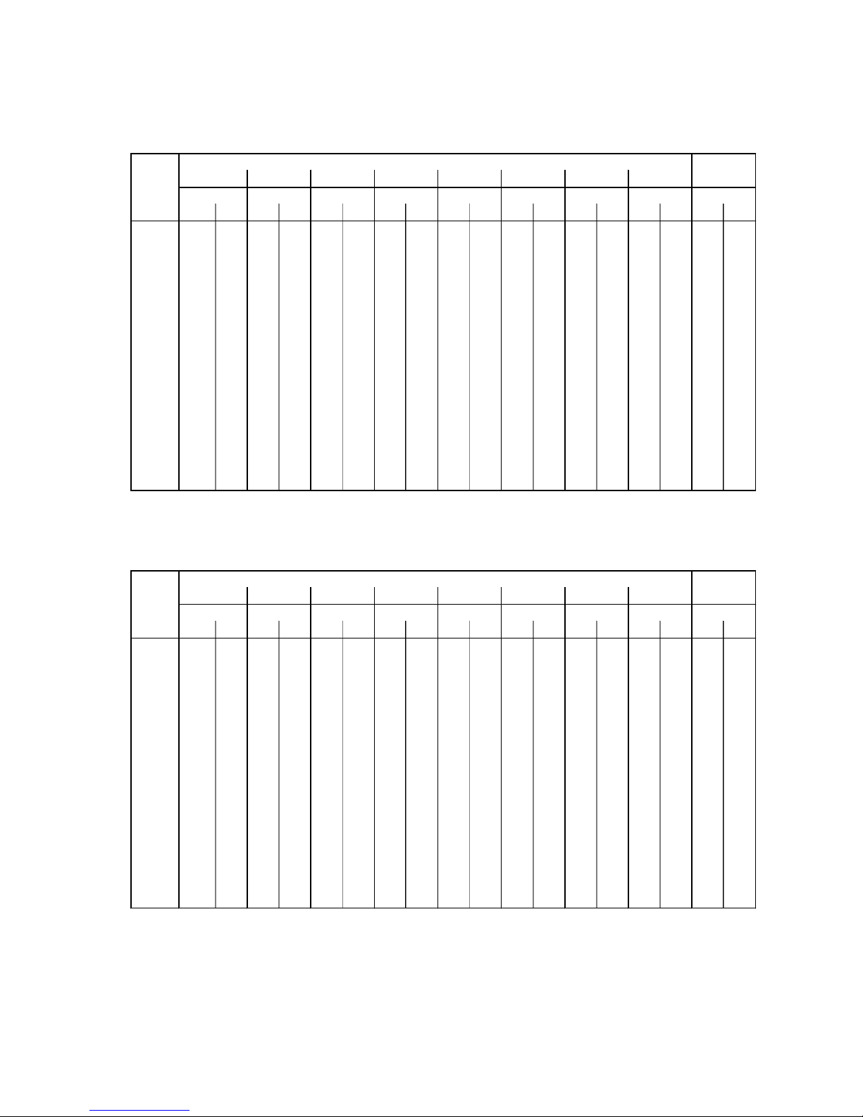
Blue Box - 21
SOUND POWER AND PRESSURE LEVELS
STANDARD UNITS
LOW NOISE UNITS
ZETA
2002
Lw Lp Lw Lp Lw Lp Lw Lp Lw Lp Lw Lp Lw Lp Lw Lp Lw Lp
3.2 96,1 78,8 87,3 70,0 81,2 63,8 79,7 62,4 78,6 61,3 73,2 55,9 69,8 52,4 60,7 43,4 83,0 65,7
4.2 96,5 79,1 87,7 70,3 81,5 64,2 80,0 62,7 78,9 61,6 73,6 56,2 70,1 52,8 61,0 43,7 83,3 66,0
5.2 96,6 79,2 87,8 70,4 81,6 64,3 80,1 62,8 79,0 61,7 73,7 56,3 70,2 52,9 61,1 43,8 83,4 66,1
6.2 97,3 79,9 88,5 71,1 82,3 65,0 80,8 63,5 79,7 62,4 74,4 57,0 70,9 53,6 61,8 44,5 84,1 66,8
7.2 97,5 80,1 88,7 71,3 82,5 65,2 81,0 63,7 79,9 62,6 74,6 57,2 71,1 53,8 62,0 44,7 84,3 67,0
8.2 98,1 80,8 89,3 72,0 83,2 65,8 81,7 64,4 80,6 63,2 75,2 57,9 71,8 54,4 62,7 45,3 85,0 67,7
9.2 99,7 81,8 90,9 73,0 84,8 66,8 83,3 65,4 82,2 64,2 76,9 58,9 73,4 55,4 64,3 46,3 86,6 68,7
10.2 100,0 82,0 91,2 73,2 85,0 67,0 83,5 65,6 82,4 64,5 77,1 59,1 73,6 55,6 64,5 46,6 86,8 68,9
12.2 100,1 82,2 91,3 73,4 85,1 67,3 83,7 65,8 82,6 64,7 77,2 59,3 73,7 55,9 64,7 46,8 87,0 69,1
13.2
100,3 82,3 91,5 73,5 85,3 67,3 83,8 65,9 82,7 64,8 77,4 59,4 73,9 55,9 64,8 46,9 87,1 69,2
14.4
101,1 82,5 92,3 73,7 86,1 67,5 84,6 66,0 83,5 64,9 78,2 59,6 74,7 56,1 85,6 47,0 87,9 69,3
16.4
103,6 85,0 94,8 76,2 88,6 70,1 87,2 68,6 86,1 67,5 80,7 62,1 77,2 58,7 68,2 49,6 90,5 71,9
18.4
104,5 85,4 95,7 76,6 89,6 70,5 88,1 69,0 87,0 67,9 81,6 62,5 78,2 59,1 69,1 50,0 91,4 72,3
20.4 105,2 86,1 96,4 77,3 90,3 71,2 88,8 69,7 87,7 68,6 82,3 63,2 78,9 59,8 69,8 50,7 92,1 73,0
24.4 106,1 87,0 97,3 78,2 91,2 72,1 89,7 70,6 88,6 69,5 83,2 64,1 79,8 60,7 70,7 51,6 93,0 73,9
26.4 106,2 87,1 97,4 78,3 91,3 72,2 89,8 70,7 88,7 69,6 83,3 64,2 79,9 60,8 70,8 51,7 93,1 74,0
dB dB dB
Total
dB(A)dB dB dB dB
Octave band [Hz]
63
dB
125 250 500 1000 2000 4000 8000
ZETA
2002
/LN Lw Lp Lw Lp Lw Lp Lw Lp Lw Lp Lw Lp Lw Lp Lw Lp Lw Lp
3.2 93,4 76,0 84,6 67,2 78,4 61,1 76,9 59,6 75,8 58,5 70,5 53,1 67,0 49,7 57,9 40,6 80,2 62,9
4.2 93,5 76,2 84,7 67,4 78,5 61,3 77,0 59,8 75,9 58,7 70,6 53,3 67,1 49,9 58,0 40,8 80,3 63,1
5.2 93,7 76,4 84,9 67,6 78,7 61,5 77,2 60,0 76,1 58,9 70,8 53,5 67,3 50,1 58,2 41,0 80,5 63,3
6.2 94,3 77,0 85,5 68,2 79,3 62,1 77,8 60,6 76,7 59,5 71,4 54,1 67,9 50,7 58,8 41,6 81,1 63,9
7.2 94,4 77,1 85,6 68,3 79,4 62,2 77,9 60,7 76,8 59,6 71,5 54,2 68,0 50,8 58,9 41,7 81,2 64,0
8.2 96,3 79,0 87,5 70,2 81,3 64,1 79,8 62,6 78,7 61,5 73,4 56,1 69,9 52,7 60,8 43,6 83,1 65,9
9.2 97,3 79,0 88,5 70,6 82,3 64,5 80,9 63,0 79,8 61,9 74,4 56,5 70,9 53,1 61,9 44,0 84,2 66,3
10.2 97,8 79,5 89,0 71,1 82,8 65,0 81,4 63,5 80,3 62,4 74,9 57,0 71,4 53,6 62,4 44,5 84,7 66,8
12.2 97,3 79,0 88,5 70,6 82,3 64,5 80,9 63,0 79,8 61,9 74,4 56,5 70,9 53,1 61,9 44,0 84,2 66,3
13.2 97,6 79,3 88,8 70,9 82,6 64,8 81,2 63,3 80,1 62,2 74,7 56,8 71,2 53,4 62,2 44,3 84,5 66,6
14.4 99,1 80,5 90,3 71,7 84,1 65,5 82,6 64,0 81,5 62,9 76,2 57,6 72,7 54,1 63,6 45,0 85,9 67,3
16.4 101,8 82,6 93,0 74,4 86,8 68,3 85,4 66,8 84,3 65,7 78,9 60,3 75,4 56,9 66,4 47,8 88,7 70,1
18.4 102,6 82,7 93,8 74,7 87,7 68,6 86,2 67,1 85,1 66,0 79,7 60,6 76,3 57,2 67,2 48,1 89,5 70,4
20.4 103,0 83,1 94,2 75,1 88,1 69,0 86,6 67,5 85,5 66,4 80,1 61,0 76,7 57,6 67,6 48,5 89,9 70,8
24.4 103,9 84,0 95,1 76,0 89,0 69,9 87,5 68,4 86,4 67,3 81,0 61,9 77,6 58,5 68,5 49,4 90,8 71,7
26.4 104,0 84,1 95,2 76,1 89,1 70,0 87,6 68,5 86,5 67,4 81,1 62,0 77,7 58,6 68,6 49,5 90,9 71,8
Total
dB dB dB dB dB dB dB dB dB(A)
Octave band [Hz]
63 125 250 500 1000 2000 4000 8000
Lw: sound power values in free field conditions are calculated in accordance with ISO 3746.
Lp : sound pressure values measured at 1 m from the unit in free field conditions in compliance with ISO 3746
Page 28
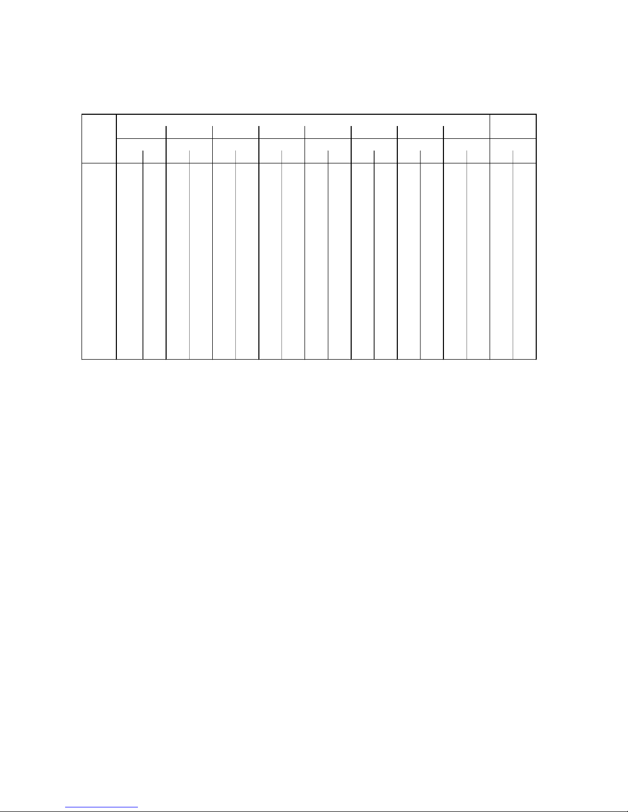
Blue Box - 22
EXTRA LOW NOISE UNITS
SOUND POWER AND PRESSURE LEVELS
ZETA
2002
/SLN Lw Lp Lw Lp Lw Lp Lw Lp Lw Lp Lw Lp Lw Lp Lw Lp Lw Lp
3.2 90,2 73,0 81,4 64,2 75,3 58,1 73,8 56,6 72,7 55,5 67,3 50,1 63,9 46,7 54,8 37,6 77,1 59,9
4.2 90,6 73,5 81,8 64,7 75,7 58,6 74,2 57,1 73,1 56,0 67,7 50,6 64,3 47,2 55,2 38,1 77,5 60,4
5.2 91,1 73,9 82,3 65,1 76,2 59,0 74,7 57,5 73,6 56,4 68,2 51,0 64,8 47,6 55,7 38,5 78,0 60,8
6.2 91,8 74,6 83,0 65,8 76,9 59,7 75,4 58,2 74,3 57,1 68,9 51,7 65,5 48,3 56,4 39,2 78,7 61,5
7.2 92,1 74,9 83,3 66,1 77,2 60,0 75,7 58,5 74,6 57,4 69,2 52,0 65,8 48,6 56,7 39,5 79,0 61,8
8.2 94,8 76,8 86,0 68,0 79,9 61,9 78,4 60,4 77,3 59,3 71,9 53,9 68,5 50,5 59,4 41,4 81,7 63,7
9.2 95,0 77,1 86,2 68,3 80,1 62,2 78,6 60,7 77,5 59,6 72,1 54,2 68,7 50,8 59,6 41,7 81,9 64,0
10.2 95,7 77,8 86,9 69,0 80,8 62,9 79,3 61,4 78,2 60,3 72,8 54,9 69,4 51,5 60,3 42,4 82,6 64,7
12.2 95,3 77,4 86,5 68,6 80,4 62,5 78,9 61,0 77,8 59,9 72,4 54,5 69,0 51,1 59,9 42,0 82,2 64,3
13.2 95,6 77,7 86,8 68,9 80,7 62,8 79,2 61,3 78,1 60,2 72,7 54,8 69,3 51,4 60,2 42,3 82,5 64,6
14.4 97,1 78,1 88,3 69,3 82,1 63,1 80,6 61,6 79,5 60,5 74,2 55,2 70,7 51,7 61,6 42,6 83,5 64,9
16.4 99,6 81,0 90,8 72,2 84,7 66,1 83,2 64,6 82,1 63,5 76,7 58,1 73,3 54,7 64,2 45,6 86,5 67,9
18.4 100,1 80,9 91,3 72,1 85,2 66,0 83,7 64,5 82,6 63,4 77,2 58,0 73,8 54,6 64,7 45,5 87,0 67,8
20.4 100,7 81,5 91,9 72,7 85,8 66,6 84,3 65,1 83,2 64,0 77,8 58,6 74,4 55,2 65,3 46,1 87,6 68,4
24.4 101,6 82,5 92,8 73,7 86,7 67,6 85,2 66,1 84,1 65,0 78,7 59,6 75,3 56,2 66,2 47,1 88,5 69,4
26.4 102,3 82,7 93,5 73,9 87,4 67,8 85,9 66,3 84,8 65,2 79,4 59,8 76,0 56,4 66,9 47,3 89,2 69,6
Octave band [Hz]
63 125 250 500 1000 2000 4000 8000
Total
dB dB dB dB dB dB dB dB dB(A)
Lw: sound power values in free field conditions are calculated in accordance with ISO 3746.
Lp : sound pressure values measured at 1 m from the unit in free field conditions in compliance with ISO 3746
Page 29
Blue Box - 23
Attention: before repairing or servicing the unit, ensure that the electrical
supply is disconnected.
Any work on the unit must be carried out by trained people only.
1. FIELD OF APPLICATION
The equipment is designed for cooling (chiller only versions) or cooling/heating (heat pump version) water, which
is usually utilised for air conditioning or refrigeration applications.
The units must be used exclusively within the operating limits specified in Section 4.
1.1 INTRODUCTION
- When installing or servicing the unit, it is necessary to strictly follow the rules described in this manual, to
conform to all the items detailed on the unit labels and take any necessary precaution.
- Pressure in refrigerant circuits and danger from electrical shock can be hazardous when installing or servicing the
unit.
- The warranty will be invalid if the rules described in this manual are not observed and if any modifications are
made to the unit without prior authorisation of the manufacturer.
2. INSPECTION, TRANSPORT, SITE HANDLING
2.1 INSPECTION
After receiving the unit, immediately check its integrity. The unit will have left the factory in perfect condition.
Therefore on receiving the unit any damage must be verbally described to the carrier and recorded on the
Delivery Note before it is signed by both parties. Blue Box or their Agent must be informed as soon as possible of
the extent of the damage.
The Customer should prepare a written statement and photographic evidence regarding any severe damage.
2.2 LIFTING AND SITE HANDLING
Avoid sudden movements and jolts when unloading and positioning the unit. Internal handling procedures must
be conducted with care. Do not exert leverage on the components of the machine. The unit must be lifted by
inserting steel tubes through the lifting attachments shown by the relative signs (yellow arrow).
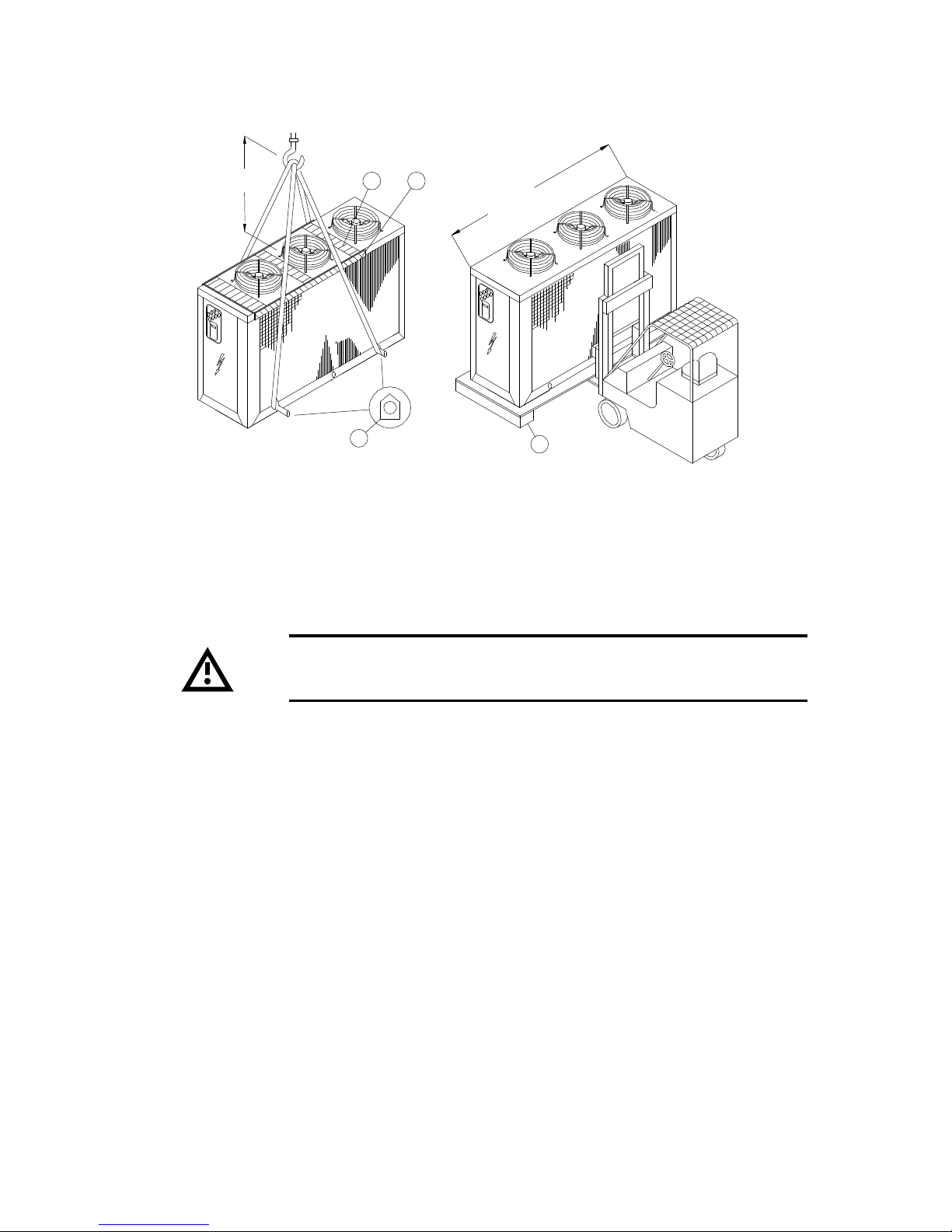
The unit must be lifted by harnessing it as shown in figure 1: use ropes or straps of sufficient length and spacer
bars to avoid damage to the unit’s side panels and cover. Alternatively, the unit (with a maximum length less than
3.5 m) can be lifted by a forklift truck, inserting the forks under the pallet.
Page 30
Blue Box - 24
Caution: ensure that the method of lifting does not allow the unit to slip
from chains and slings and does not allow the unit to turn over or slide
from lifting devices.
2.3 UNPACKING
When unpacking the unit pay attention not to damage the unit.
Packaging consists of different materials: wood, paper, nylon etc.
Separate the materials and deliver to the proper gathering centre in order to reduce their environmental impact.
Figure 1
2.5 m min.
mind. 2.5 m
3
1 2
4
3.5 m max
(1) Space bar (not supplied)
(2) Side panel protection (not supplied)
(3) Lifting holes
(4) Pallet
Page 31

Blue Box - 25
3. SAFETY PRECAUTIONS
3.1 DEFINITION OF DANGER ZONE
Only authorised operators must be allowed in the vicinity of the unit.
- The external danger zone concerns a space of approximately 2 m in width around the perimeter of the machine.
Access to this area must be prevented by suitable guarding in the event that the unit is located in an unprotected
area that is easily accessible to unauthorised persons.
- The internal danger zone is defined as the interior of the machine. Access to the interior of the machine must
not be permitted to unqualified personnel and never before the machines' electrical supply has been disconnected.
3.2 SAFETY PRESCRIPTIONS
The unit is designed and built in accordance with the PED 97/23CE rules, to ensure the maximum level of safety.
To avoid possible situations of risk adhere to the following rules at all times:
- All work on the unit must be performed by qualified personnel. Before working on the unit, ensure that the
designated personnel are conversant with the documentation supplied. Always ensure there is a copy of the
documentation in the immediate vicinity of the unit.
- Use the appropriate personal safety equipment (gloves, helmet, safety goggles, safety footwear, etc.) for all
maintenance and control operations on the unit.
- Use only tools and equipment that are in good working order.
- The fans have protective grilles to prevent accidental contact. Use the maximum caution to avoid inserting or
dropping objects through the grilles.
- The exchanger coils have sharp edges. Do not touch the coils without using suitable protection.
- The compressor compartment contains various high temperature components. Adopt the maximum caution
when working in the vicinity of the compressors and avoid touching any parts of the unit without appropriate
protection.
- Do not work within the theoretical discharge trajectory of the relief valves.
Page 32

Blue Box - 26
MECHANICAL HAZARDS
Operating mode Analysed risk or hazard Solution adopted
Normal operating regime
Maintenance
Stability Because of their intrinsic characteristics, the
units are not associated with problems of
possible falling or tipping while in operation.
Carefully read the items described in this
manual concerning the methods of
positioning the unit.
Handling during transport
and installation.
Stability The unit's base frame has specific lifting
holes; the positions of which are marked
with yellow decals. Following this procedure
will eliminate the risk of the unit tipping.
Carefully read the items descriptions in this
manual concerning the methods of handling
the unit.
Normal operating regime
Maintenance
Pipeline bursts. Pipes are rigidly anchored to reduce the
degree of vibration.
Operating regime
Surfaces, sharp corners and
edges.
The machine is designed and built in such a
way as to minimise the presence of sharp
corners and edges as far as possible.
Maintenance Surfaces, sharp corners and
edges.
In the interior parts of the unit it is not
possible to totally eliminate risks from the
presence of surfaces, sharp corners and
edges. The operating, installation, and
maintenance manual specifies that
maintenance operations should be carried
out exclusively by qualified personnel, and
provides indications of the protective
equipment to be used.
Normal operating regime Cutting or severing. The moving parts of the unit are located in
clearly defined areas. Specifically, the fans
are enclosed in an inaccessible compartment
and are equipped with an upper protection
grille to UNI EN 294. All the protections
supplied to limit and enclose the fan
compartments cannot be removed without
the use of special tools.
Maintenance Cutting or severing. The moving parts of the unit are located in
clearly defined areas. Specifically, the fans
are enclosed in an inaccessible compartment
and are equipped with an upper protective
grille to UNI EN 294. If present, the fan
speed regulator accessory, located in the
condensing section compartment, does not
require adjustment or calibration during
maintenance operations.
Normal operating regime Cutting or severing. All units are supplied as standard with
specific protection grilles designed to protect
against accidental contact with the finned
coils, which can cause minor cuts to the
hands.
Page 33

Blue Box - 27
MECHANICAL HAZARDS
THERMAL HAZARDS
Operating mode Analysed risk or hazard Solution adopted
Maintenance Cutting or severing. The operating, installation, and maintenance
manual describes the use of suitable
protections to avoid contact with the finned
coils, which can cause slight wounds to the
hands.
Normal operating regime
Entanglement, dragging,
impact.
The moving parts of the unit are located in
clearly defined areas. Specifically, the fans
are enclosed in an inaccessible compartment
and they are equipped with an upper
protective grille to UNI EN 294. All the
protections supplied to limit and enclose the
fan compartments cannot be removed
without the use of special tools.
Maintenance Entanglement, dragging,
impact.
The moving parts of the unit are located in
clearly defined areas. Specifically, the fans
are enclosed in an inaccessible compartment
and they are equipped with an upper
protective grille to UNI EN 294.
If present, the fan speed regulator accessory,
located in the condensing section
compartment, does not require adjustment
or calibration during maintenance
operations.
Normal operating regime
Maintenance
Projection of high pressure jets
of fluid - Explosion hazard
All units are equipped with relief valves to
eliminate the risk of pressure bursts.
The outlet from relief valves must be piped
appropriately to eliminate risks associated
with the expulsion of gas at high pressure
from the machine. The warnings regarding
these expulsion points are fixed to the
outside of the unit and given in the
operating and maintenance manual.
Operating mode Analysed risk or hazard Solution adopted
Normal operating regime
Burns caused by high
temperatures.
Most of the pipelines that could cause burns,
when touched, are lagged with heat
insulating material. All the parts that are
potentially dangerous are confined in
compartments that cannot be accessed
without the use of tools
Maintenance
Burns caused by high
temperatures.
Most of the pipelines that could cause burns,
when touched, are lagged with heat
insulating material. The operating,
installation, and maintenance manual
describes the use of suitable protections to
avoid contact with high temperature
pipelines that could result in burns.
Page 34
Blue Box - 28
NOISE-RELATED HAZARDS
ELECTRICAL HAZARDS
Operating mode Analysed risk or hazard Solution adopted
Normal operating regime
Maintenance
Contact with electrically live
parts (direct contact).
Normal operating regime
Maintenance
Elements carrying electrical
current in the case of faults.
Normal operating regime
Maintenance
Inappropriate insulation.
Normal operating regime
Maintenance
Radiated heat due to short-
circuits or overloads.
All units are designed and built in
compliance with harmonised standard EN
60204-1.
Operating mode Analysed risk or hazard Solution adopted
Normal operating regime
Maintenance
Hearing damage. All units are designed and built with the aim
of reducing noise emissions to the minimum.
Page 35
Blue Box - 29
R407C REFRIGERANT SAFETY SHEETS
Identification of the
preparation:
407C
Synonyms: HFC-32lHFC-125IHFG134a
Formula: Mixture
1. IDENTIFICATION OF
THE SUBSTANCE
1.1
EE-No: difluoromethane (HFC-32) : 200-839-4
1-1-1-2-tetrafluoroethane UHFC-134a) : 212-377-0
pentafluoroethane (HFC-125) : 206-557-8
Chemical Name CAS-No - Wt % - Symbol(s): & phrases "R"
difluoromethane 75/10/5 - 23 - F+;R12
1-2-2-2-tetrafluoroethane 811/97/2 - 52
2. COMPOSITION /
INFORMATION ON
INGREDIENTS
pentafluoroethane 354/33/ 6 - 25
3. HAZARDS
IDENTIFICATION:
3.1 Most important
hazards:
Liquefied gas: may cause frostbite. Contact with eyes may cause
irritation.
Eyes Rinse immediately with plenty of water for at least 15 minutes.
Keep eye wide open while rinsing. If symptoms persist, call a
physician.
Skin Liquefied gas may cause frostbite. Wash frostbitten areas with
plenty of water. Do not remove clothing. Wash off with warm
water. if skin irritation persists, call a physician.
Inhalation Move to fresh air in case of accidental inhalation of vapours.
Oxygen or artificial respiration if needed. Do not apply artificial
respiration if patient is breathing; Consult a physician after
significant exposure. Do not give adrenaline or similar drugs.
Ingestion Do not induce vomiting without medical advice. Call a physician
immediately. Do not give drugs from adrenaline-ephedrine
group.
4. FIRST-AID
MEASURES:
4.1
General advice Consult a physician alter significant exposure.
5.1 Suitable extinguishing
media:
The product itself does not burn. Extinguish with carbon dioxide,
dry chemical, foam or water spray. Use extinguishing measures
that are appropriate to the environment.
5.2 Extinguishing media
which must not be
used for safety reasons:
None
5.3 Specific hazards: Possibility of generating hazardous reactions during a fire due to
the presence of F and/or Cl groups. Fire or intense heat may
cause violent rupture of packages.
5.4 Special protective
equipment for firefighters:
In case of fire, west a self contained breathing apparatus.
Protective suit.
5. FIRE-FIGHTING
MEASURES:
5.5 Specific methods: Standard procedure for chemical fires. In the event of fire, cool
tanks with water spray.
6.1 Personal precautions: Use personal protective equipment. Evacuate personnel to safe
areas. Do not breath vapours or spray mist. Ensure adequate
ventilation.
6. ACCIDENTAL
RELEASE MEASURES:
6.2 Methods for cleaning
up:
Shut off leaks it without risk. Solid evaporates. Ensure adequate
ventilation.
Page 36
Blue Box - 30
7.1 Handling: Keep away from heat, sources of ignition. Do not puncture or
drop container, Provide sufficient air exchange and / or exhaust in
work rooms.
7. HANDLING AND
STORAGE:
7.2 Storage: Keep containers tightly closed in a cool, well-ventilated place.
Store in a cool and shaded area. Do not expose to temperatures
above 50 °C. Keep tightly closed.
8.1 Engineering measures
to reduce exposure:
Ensure adequate ventilation, especially in confined areas.
Personal protection
equipment:
Respiratory protection: In case of insufficient ventilation wear suitable respiratory
equipment, preferably a compressed airline breathing apparatus.
Hand protection: Impervious butyl rubber gloves.
Eye protection: Wear as appropriate: safety glasses, gaggles, Wear face-shield
and protective suit for abnormal processing problems.
8.2
Skin and body
protection:
Chemical resistant apron, long sleeved clothing, safety shoes.
8. EXPOSURE
CONTROLS /
PERSONAL
PROTECTION:
8.3 Exposure limit(s): 1-1-1-2-tetrafluoroethane 1000 ppm (TWA);
difluoromethane: 1000 ppm (TWA);
pentafluoroethane: 1000 ppm (TWA)(AIHA);
9.1 Stability: Stable at normal conditions. No decomposition if stored and
applied as directed. Decomposition starting from 250°C.
9.2 Conditions to avoid: Do not expose to temperatures above 50 °C. Fire or Intense heat
may cause violent rupture of packages.
9.3 Materials to avoid: alkaline metals (Na, K), alkaline earth metals (Ca, Mg), finely
divided aluminium, zinc.
9. STABILITY AND
REACTIVITY:
9.4 Hazardous
decomposition
products:
halogenated compounds, hydrogen halides (HF, HCI), carbonyl
halides (COCl2), carbon monoxide, carbon dioxide (C02).
10.1 Acute toxicity: LC50/inh./4 h/rat : > 500000 ppm
10.2 Irritation :
Skin: slightly irritant, may cause frostbite.
Eyes: slightly irritant.
10. TOXICOLOGICAL
INFORMATION:
10.4 Chronic toxicity: chronic inhalation, no-observed-effect level (NOEL):> 10000pprn
rat.
11.1 Waste from residues /
unused products:
Offer surplus and non-recyclable solutions to an established
disposal company. In accordance with local and national
regulations. S59 - Refer to manufacturer/supplier for information
on recovery/recycling.
11. DISPOSAL
CONSIDERATIONS:
Contaminated
packaging:
Do not reuse empty containers. Empty pressure vessels should be
returned to supplier.
No. O.N.U. 3340 12. TRANSPORT
INFORMATIQN:
ADR/RID UN 3340 Refrigerant gas R407C, 2, 2° A, ADR/RID
Label: 2
Page 37
Blue Box - 31
R22 REFRIGERANT SAFETY SHEETS
Identification of the
preparation:
HCFC-22
Synonyms: chlorodifluoromethane
Formula: CHClF2
CAS-No 75-45-6
1. IDENTIFICATION OF
THE SUBSTANCE
1.1
EEC-No 200-871-9
Chemical Name CAS-No - Wt % - Symbol(s): & phrases "R" 2. COMPOSITION /
INGREDIENTS
Chlorodifluoromethane 75/45/6 - 100 - R59
3. HAZARDS 3.1 Major hazards: Causes damage to ozone layer.
Eyes Rinse immediately with plenty of water for at least 15 minutes.
Keep eye wide open while rinsing. If symptoms persist, call a
physician.
Skin Liquefied gas may cause frostbite. Wash frostbitten areas with
plenty of water. Do not remove clothing. Wash off with warm
water. if skin irritation persists, call a physician.
Inhalation Move to fresh air in case of accidental inhalation of vapours.
Oxygen or artificial respiration if needed. Do not apply artificial
respiration if patient is breathing; Consult a physician after
significant exposure. Do not give adrenaline or similar drugs.
Ingestion Do not induce vomiting without medical advice. Call a physician
immediately. Do not give drugs from adrenaline-ephedrine
group.
4. FIRST-AID
MEASURES:
4.1
General advice Consult a physician alter significant exposure.
5.1 Suitable extinguishing
media:
The product itself does not burn. Extinguish with carbon dioxide,
dry chemical, foam or water spray. Use extinguishing measures
that are appropriate to the environment.
5.2 Extinguishing media
which must not be
used for safety reasons:
None
5.3 Specific hazards: Possibility of generating hazardous reactions during a fire due to
the presence of F and/or Cl groups. Fire or intense heat may
cause violent rupture of packages.
5.4 Special protective
equipment for firefighters:
In case of fire, west a self contained breathing apparatus.
Protective suit.
5. FIRE-FIGHTING
MEASURES:
5.5 Specific methods: Standard procedure for chemical fires. In the event of fire, cool
tanks with water spray.
6.1 Personal precautions: Use personal protective equipment. Evacuate personnel to safe
areas. Do not breath vapours or spray mist. Ensure adequate
ventilation.
6. ACCIDENTAL
RELEASE MEASURES:
6.2 Methods for cleaning
up:
Shut off leaks it without risk. Solid evaporates. Ensure adequate
ventilation.
Page 38
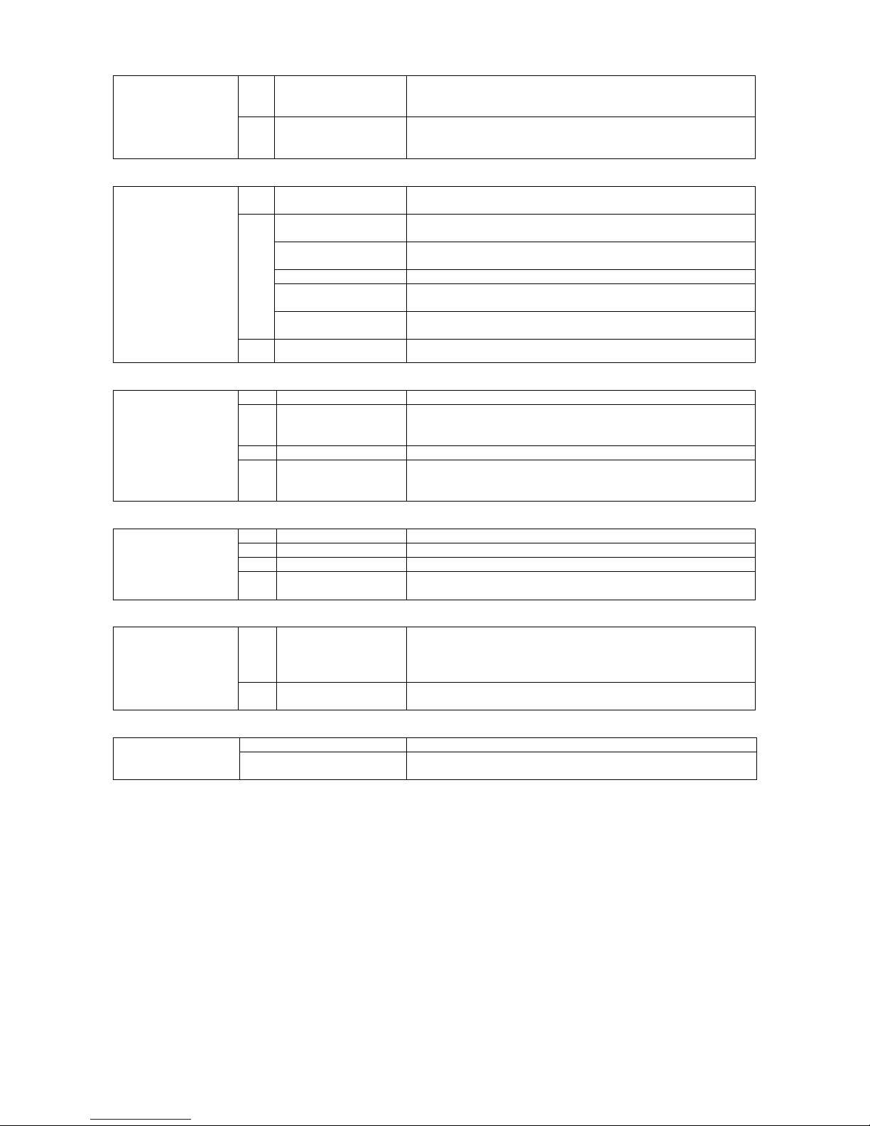
Blue Box - 32
7.1 Handling: Keep away from heat, sources of ignition. Do not puncture or
drop container. Provide sufficient air exchange and / or exhaust in
work rooms.
7. HANDLING AND
STORAGE:
7.2 Storage: Keep containers tightly closed in a cool, well-ventilated place.
Store in a cool and shaded area. Do not expose to temperatures
above 50 °C. Keep tightly closed.
8.1 Engineering measures
to reduce exposure:
Ensure adequate ventilation, especially in confined areas.
Personal protection
equipment:
Respiratory protection: In case of insufficient ventilation wear suitable respiratory
equipment, preferably a compressed airline breathing apparatus.
Hand protection: Impervious butyl rubber gloves.
Eye protection: Wear as appropriate: safety glasses, gaggles, Wear face-shield
and protective suit for abnormal processing problems.
8.2
Skin and body
protection:
Chemical resistant apron, long sleeved clothing, safety shoes.
8. EXPOSURE
CONTROLS /
PERSONAL
PROTECTION:
8.3 Exposure limit(s): Chlorodifluoromethane: 3600 mg/m3, 1000 ppm (TLV)
9.1 Stability: Stable
9.2 Conditions to avoid: Keep well clear of naked flame and sparks. Do not smoke. If
burned, the product can give off toxic fumes . use self-contained
breathing apparatus.
9.3 Materials to avoid: alkaline earth metals, alkaline metals, aluminium precipitate, zinc.
9. STABILITY AND
REACTIVITY:
9.4 Hazardous
decomposition
products:
halogenated compounds (e. g. acids), carbonyl halides.
10.1 Acute toxicity: LC50/inh./4 h/rat : > 300,000 ppm
10.2 Irritation:
10.3 Sensitisation: Hearth sensitisation: 50,000 ppm
10. TOXICOLOGICAL
INFORMATION:
10.4 Chronic toxicity: Sub-chronic exposure, effects not observed below level (NOEL):
10,000 ppm
11.1 Waste from residues /
unused products:
Offer surplus and non-recyclable solutions to an established
disposal company. In accordance with local and national
regulations. S59 - Refer to manufacturer/supplier for information
on recovery/recycling.
11. DISPOSAL
CONSIDERATIONS:
Contaminated
packaging:
Do not reuse empty containers. Empty pressure vessels should be
returned to supplier.
No. O.N.U. 1018 12. TRANSPORT
INFORMATIQN:
ADR/RID UN 1018 Chlorodifluoromethane, 2, 2° A, ADR/RID
Label: 2
Page 39
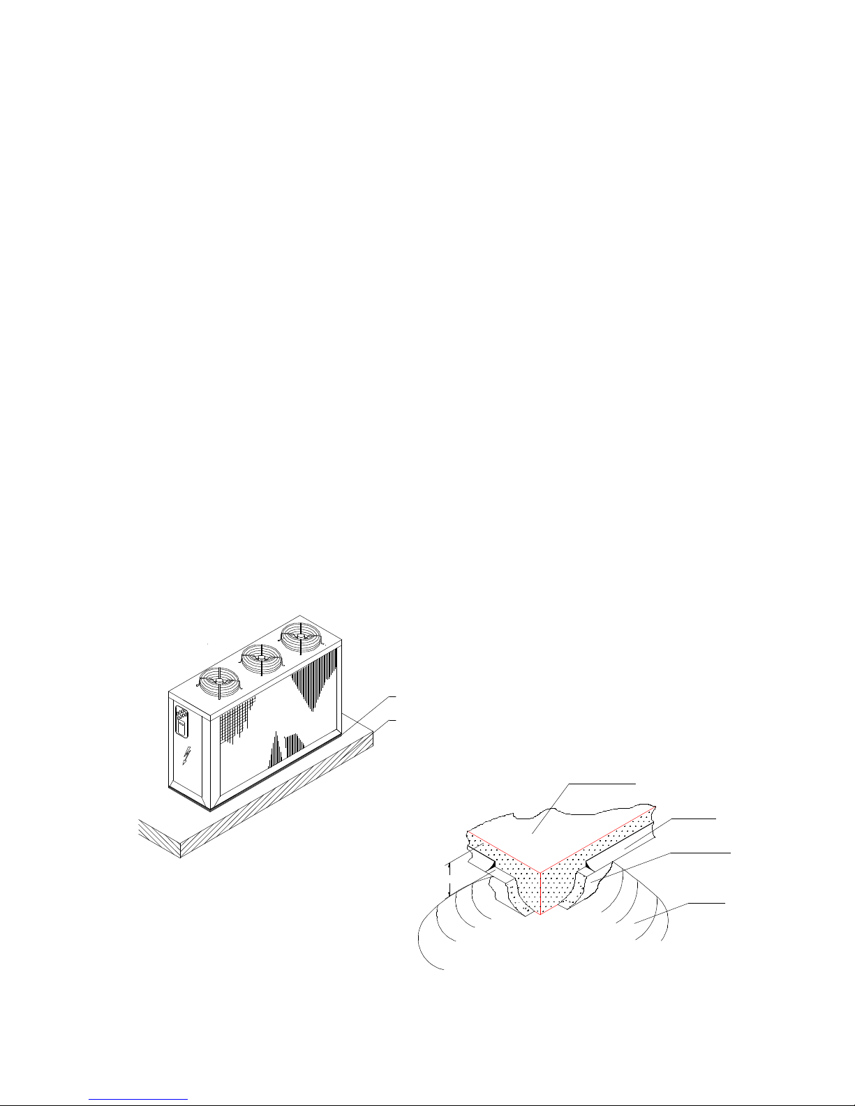
Blue Box - 33
3.3 POSITIONING
Read the following points carefully when choosing the most suitable site for the unit and its connections:
- dimensions and connection point of hydraulic pipelines;
- location of the electrical power connection point;
- accessibility for maintenance and repair work;
- loading capacity and compactness of the supporting surface;
- ventilation of air-cooled condenser;
- orientation and exposure to sunlight; as far as possible the condenser coil should not be
exposed to direct sunlight;
- direction of prevailing winds: do not position the unit in such a way that prevailing winds can give rise to air
recirculation at the condenser coil;
- type of support surface: to limit the risk of overheating, do not install the unit on a dark coloured surface
(e.g.bitumen roofing membranes and compounds);
- possible sound reverberation.
All models in the ZETA 2002 series are designed for exterior installation (patios, gardens, etc.):
of undesirable air recirculation, these units must not be covered by a shelter roof or located under trees (even if
the unit is only partially covered).
It is advisable to make a supporting plinth of dimensions commensurate with the footprint of the unit. This
precaution is indispensable if the unit is to be located on unstable ground (various types of terrain, gardens, etc.).
to avoid the risks of undesirable air recirculation, these units must not be covered by a shelter roof or located
under trees (even if the unit is only partially covered).
It is advisable to make a supporting plinth of dimensions commensurate with the footprint of the unit. This
precaution is indispensable if the unit is to be located on unstable ground.
The unit transmits a low level of vibration to the supporting structure: we recommend interposing a layer of rigid
rubber sheeting between the base of the unit and the supporting surface.
If a higher level of vibration damping is required, use anti-vibration mounts (contact Bluebox for details).
The units should not be installed next to offices, bedrooms, or other areas where low noise levels are a necessity.
To avoid excess sound reverberation do not install the units in narrow or confined spaces.
Plinth slab
Sealant
Cork
underlayment
Soil
15-20 cm
Figure 2
15 mm gauge hard rubber sheet
Foundation plinth made of 500 kg/mm2 reinforced
concrete
Page 40
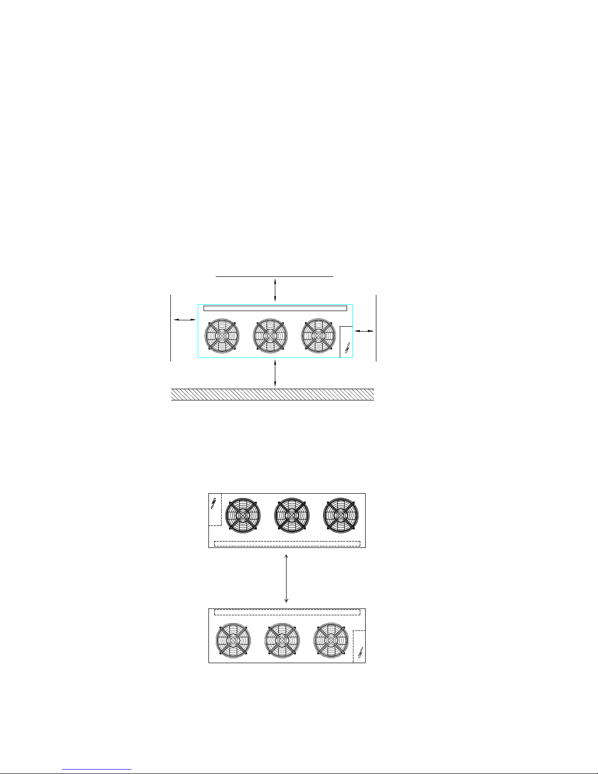
Blue Box - 34
4. INSTALLATION
4.1 INSTALLATION CLEARANCES
It is important that an adequate air volume is available at the intake and exhaust sides of the condenser coil. It is
essential to avoid air recirculation between the intake and exhaust sides to prevent a reduction of the rated
performance levels and unit operating problems.
The minimum clearances required for satisfactory operation of the unit is as follows (refer to figures 3 and 4):
- condensing coil side: 1.5 metres
- electrical panel side: 1 metre
- compressors compartment side: 1 metre
- hydraulic connection sides: 1 metre.
- top: no impediments that obstruct the air discharge.
- units installed side by side: 4 metres.
SIDE BY SIDE UNITS
4 m min.
Figure 4
Figure 3
1 m
1 m
1.5 m
1 m
Page 41
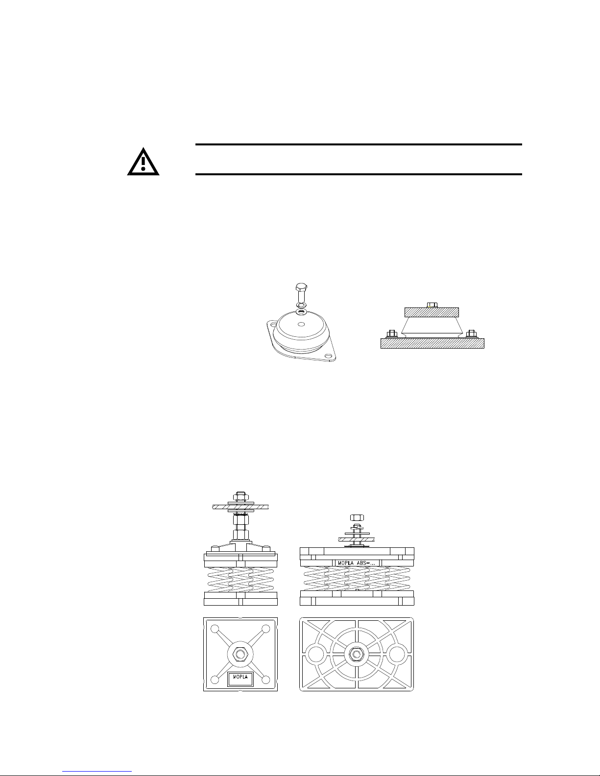
Blue Box - 35
4.2.2 Spring Anti-Vibration Isolators
Anti-Vibration Isolators with cylindrical springs are recommended to reduce any mechanical and sound vibration.
Each isolator has a code which identifies the maximum permitted load.
When installing spring Anti-Vibration Isolators, it is compulsory to carefully follow all recommendations and assembly
instructions. The dimensional drawing, enclosed in the machine, shows the footprint with the position and weight
of each isolator.
Figure 5
Spring anti-vibration
isolators for heavy
loads
The load of the unit is
supported by the full
surface of the isolators. The
load is not exerted on the
bolt.
Standard spring antivibration isolators
The isolator is fixed to the
unit's baseframe with a nut
and two bolts and washers.
Figure 6
4.2 ANTI-VIBRATION ISOLATORS (option)
It is recommended that the unit is installed on rubber or spring anti-vibration mountings, supplied as an option, to
reduce vibrations transmitted to the building structure. It is advisable to use rubber isolators for units installed in
the basement, or ground floors in contact with the earth, and spring isolators for units installed on intermediate
floors.
The anti-vibration isolators must be installed before the unit is positioned.
Ensure that during lifting the unit is firmly secured with straps.
4.2.1 Rubber Anti-Vibration Isolators
Rubber isolators are made of an upper metallic bell with a fixing screw to the base-frame of the unit. The isolator
is fixed at the foundation via 2 holes on the flange. On the flange there is a number (45, 60, 70 ShA) which
identifies the hardness of the rubber isolator. The dimensional drawing, enclosed in the machine, shows the unit
footprint with the position and weight of each isolator.
Rubber/metal anti-vibration
isolator
Designed to reduce the vibration.
Page 42

Blue Box - 36
4.3 WATER PIPING CONNECTIONS
Unit water pipework must be installed in accordance with national and local regulation and codes.
Follow the recommendations below when designing the water piping circuit (refer to the diagrams included in this
manual).
- Piping should be connected to the unit with flexible joints, to avoid vibration transmission and allow for thermal
expansion (the same procedure should be adopted for the circulating pumps).
- The following devices should be located on the piping system:
- isolating/regulating valves, temperature gauges or thermometer pockets, pressure gauges or binder points
required for servicing operations.
- Serviceable mesh strainer, with a filtration level no larger than 1mm, located on the unit inlet to prevent
debris from entering the heat exchangers.
- vent valves, to be installed in the upper parts of the circuit, for air bleeding.
- expansion device with accessories for circuit pressurisation, water thermal expansion compensation and
system filling.
- unload valve and if necessary drainage tank for circuit emptying during maintenance and seasonal stop.
Page 43
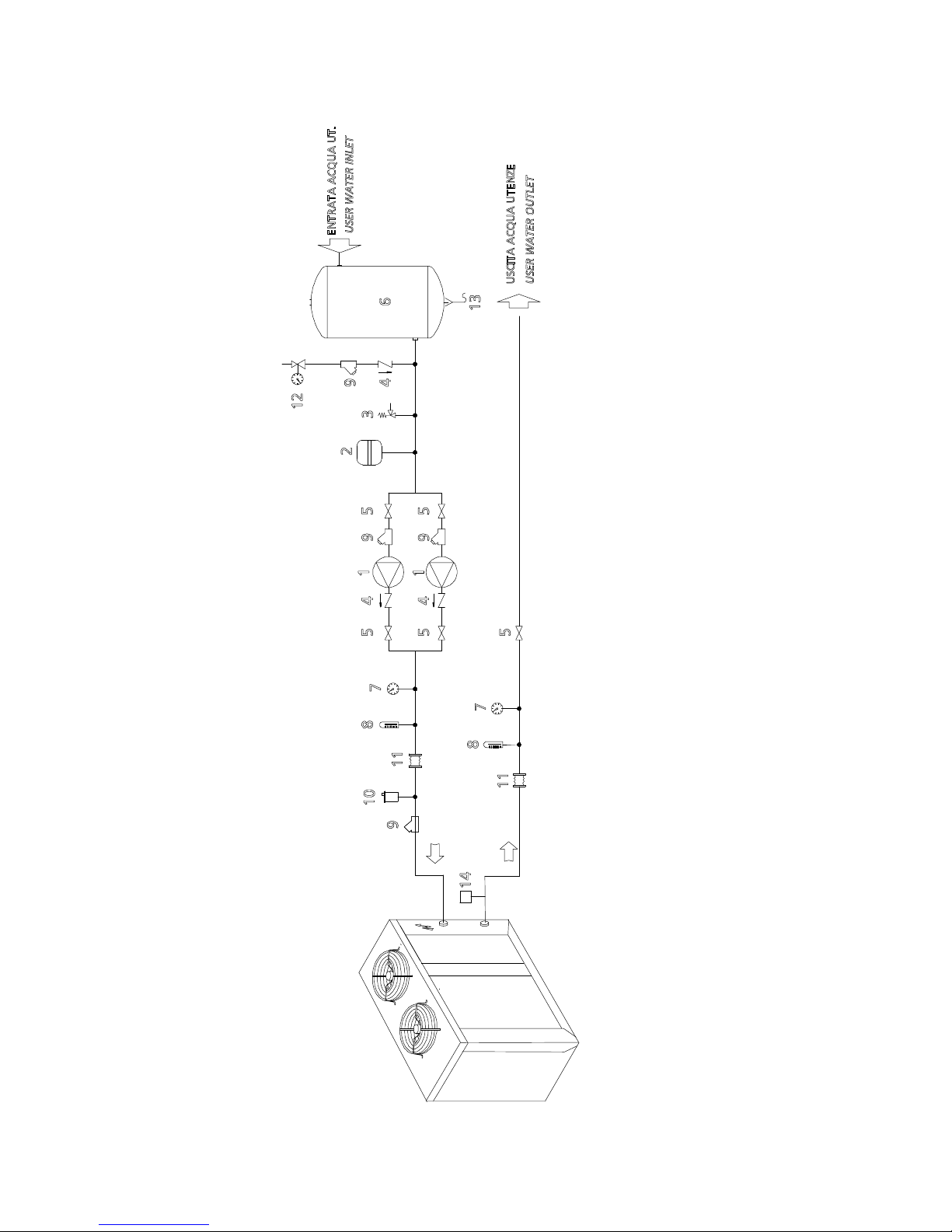
Blue Box - 37
RECOMMENDED HYDRAULIC CIRCUIT DIAGRAM FOR ZETA 2002 UNITS
1 Pump
2 Expansion tank
3 Relief valve
4 Check valve
5 Ball valve
6 Tank
7 Water pressure gauge
8 Thermometer
9 Water filter
10 Bleed valve
11 Flexible cnnection
12 Circuit filling unit
13 Water drain
14 Flow switch
Page 44
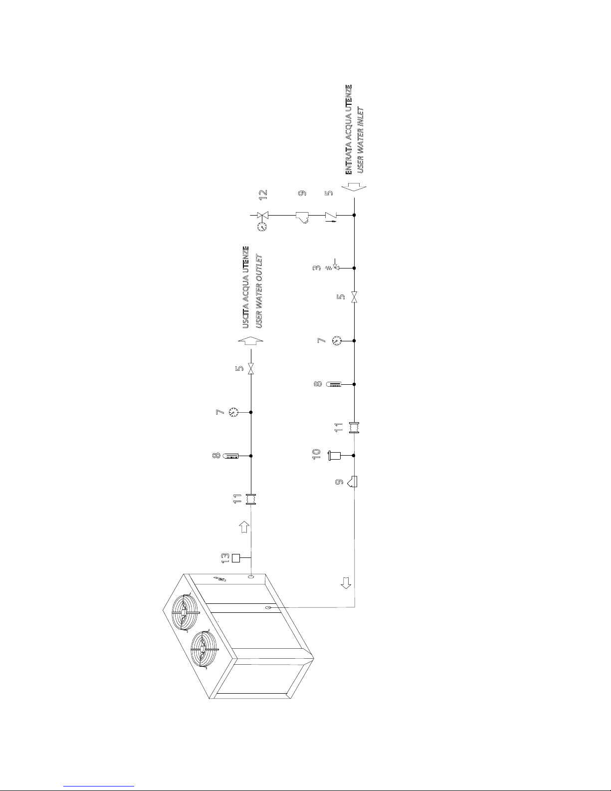
Blue Box - 38
RECOMMENDED HYDRAULIC CIRCUIT DIAGRAM FOR MODELS ZETA 2002 / ST 2PS
3 Relief valve
4 Check valve
5 Ball valve
7 Water pressure gauge
8 Thermometer
9 Water filter
10 Bleed valve
11 Flexible connection
12 Circuit filling unit
13 Flow switch
Page 45
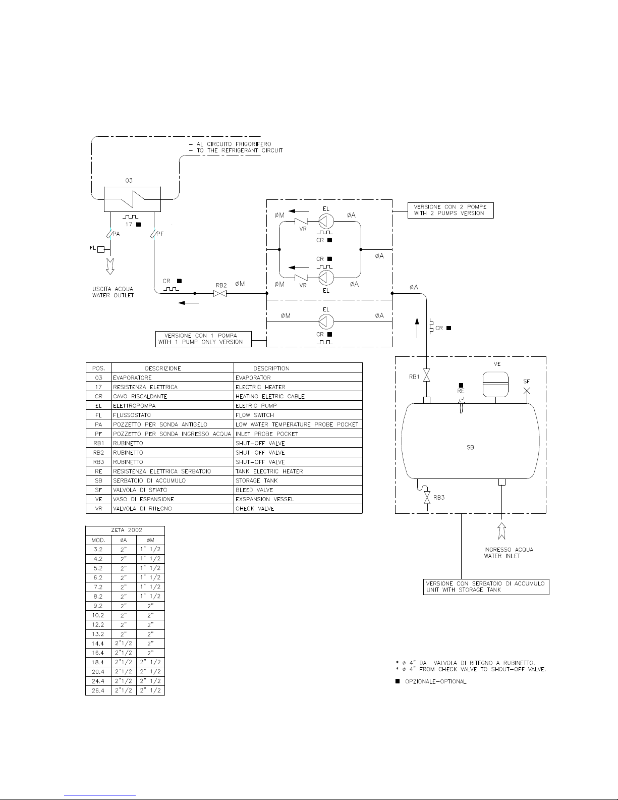
Blue Box - 39
HYDRAULIC CIRCUIT DIAGRAM VERSION ST /2PS
Page 46
Blue Box - 40
For models from 3.2 to 13.2 it is mandatory to install a flow switch
(supplied with the unit) on the evaporator water outlet connection identified
by the following decal:
For models from 14.4 to 26.4 the flow switch is already installed as part
of the standard equipment.
USER WATER
Compressors start and stop often due to changes in cooling demand. In hydraulic circuits with low water volume,
where the thermal inertia action is low, it is advisable to verify that the water volume equals or exceeds the
following ratio:
24 · Q
COMPTOT
M>= ---------------------
N
where:
M = system water content [kg]
Q
COMPTOT
= unit cooling capacity [kW]
N = number of capacity steps
If the water volume does not reach the value given by the formula, it is advisable to provide the circuit with a
storage vessel to increase the volume (tank + circuit) to match the result of the formula.
The chilled water piping and storage vessel must be insulated to prevent condensation on the pipe surfaces and
to avoid circuit performance losses.
A constant water flow to the evaporator must be guaranteed at all
operating conditions to prevent liquid refrigerant from entering the
compressor and causing irreparable damage.
If incorrectly connected the antifreeze thermostat will not operate and the evaporator may freeze.
The hydraulic connections are threaded. The type and size are indicated on the dimensional drawings at the end
of this manual.
4.4 EVAPORATOR WATER PIPE CONNECTIONS
The water inlet and outlet must be connected in the positions indicated
as labelled on the unit.
EVAPORATOR WATER
Page 47
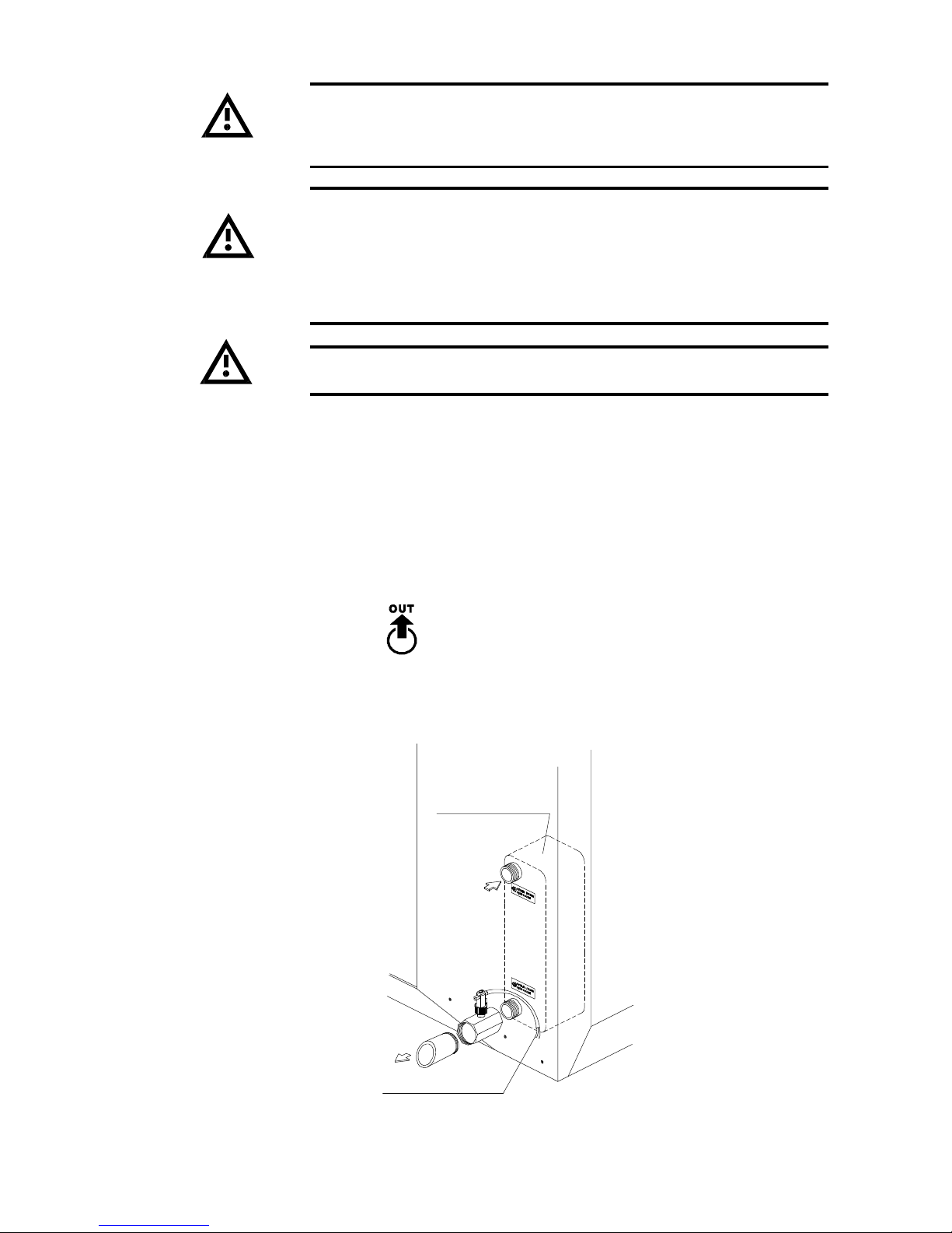
Blue Box - 41
4.5 WATER FLOW SWITCH INSTALLATION INSTRUCTIONS (models 3.2 to 13.2)
- Clean the pipeline system into which the flow switch is to be fitted and take away any magnetic particle, such
as welding residues. To prevent turbulent flow there must be straight pipework, equal to 5 times the diameter
of the pipe, either side of the flow switch.
" Connect the "T" shaped metallic manifold (on which the flow switch is mounted) into the evaporator male
threaded water outlet labelled with:
To avoid leakage, seal the connection by using teflon. The flow switch should be installed on the heat exchanger
that is closer to the electrical board.
User exchanger
(evaporator)
Make the electrical
connections on the
unit’s terminal board
Figure 7
USER WATER
Caution: When making hydraulic connections never use naked flames
close to or inside the unit.
We strongly recommend installing a pressure relief valve on the hydraulic
circuit. In the event of serious system breakdown or emergency (e.g.
fire), the relief valve will make it possible to depressurise the system
thus forestalling possible pipe bursts. Always connect the relief valve
outlet to a pipe of diameter no smaller than the valve opening, and route
it to a location in which persons are protected from the jet of expelled
water.
All units are equipped with plate heat exchangers. It is compulsory to
install a metallic filter, on the water inlet piping, with a mesh not larger
than 1 mm. If a filter is not installed the warranty will be terminated
immediately.
Page 48
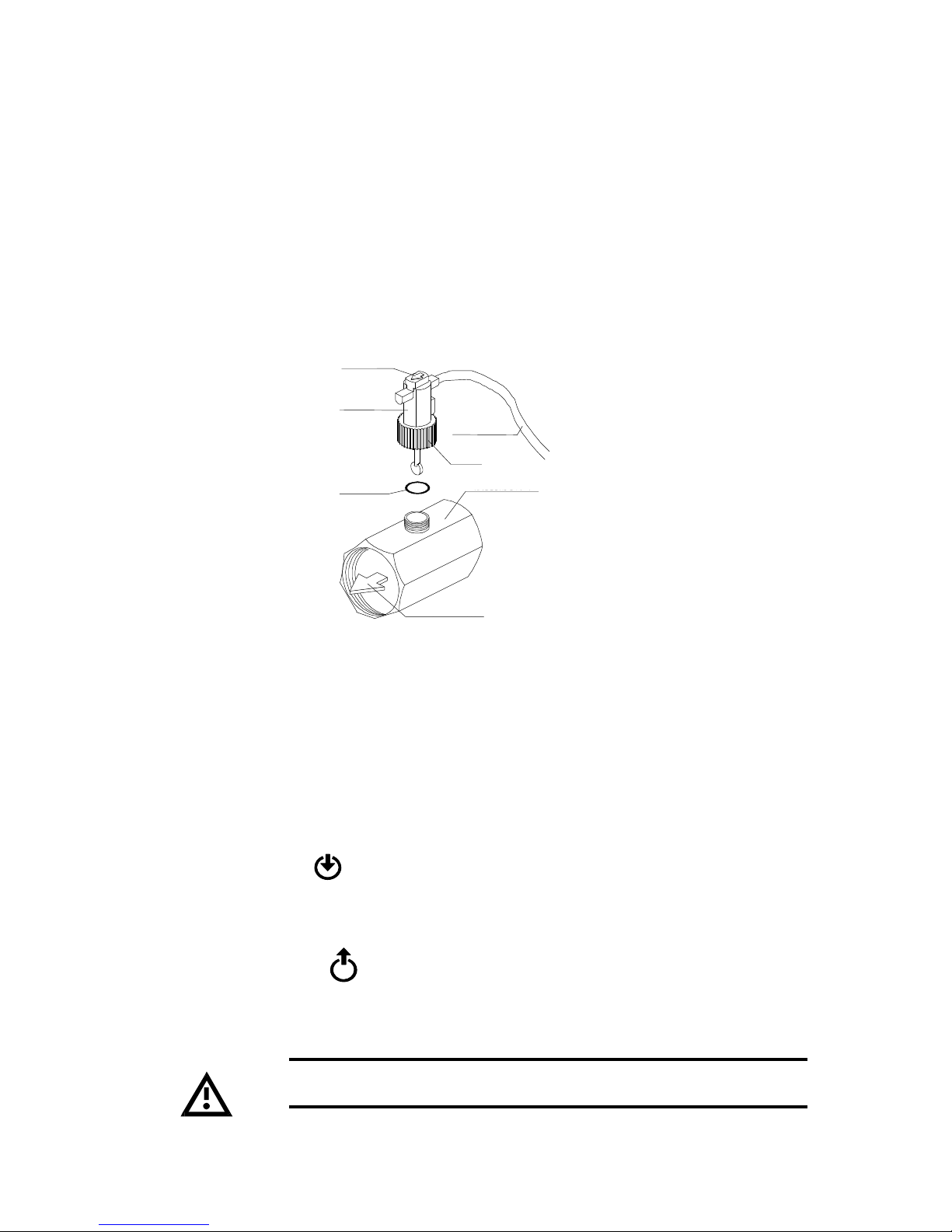
Blue Box - 42
- The flow switch must be tightened on the “T” shaped metallic manifold by the plastic knurled union nut. Check
that the arrow located on the upper side is pointing in the direction of flow.Be sure to fit the O-ring seal, through
the brass manifold and the plastic ring nut. The O-ring seal is supplied in a plastic cover to protect the flow
switch shaft.
- Connect the flow switch to the other end of the “T” manifold.
- Route the flow switch electrical cable through the hole in the unit structure and run it to the electrical panel by
ascending the upright in the machine interior. Connect the flow switch to terminals 1-14 as indicated on the
electrical drawing.
- The flow switch can be removed by screwing out the plastic knurled union nut. In order to reassemble it, ensure
that the o-ring seal is positioned in the proper location. (See figure10).
On HP version units the hydraulic connection to the desuperheater must
be isolated during heat pump operation
4.6 DESUPERHEATER HYDRAULIC CONNECTION (optional)
For all units equipped with desuperheaters the connections, for the relative hydraulic circuit, are steel tubes with
male threads.
The water inlet and outlet must be connected in the positions indicated as labelled on the unit.
Heat recovery water inlet:
Heat recovery water outlet:
Figure 8
DIREZIONE DEL FLUSSO
Arrow
Flow switch
Seal
Direction of flow
Electric cable
Ring nut
“T” Connector
OUT
WATER DESUPERHEATER
IN
WATER DESUPERHEATER
Page 49
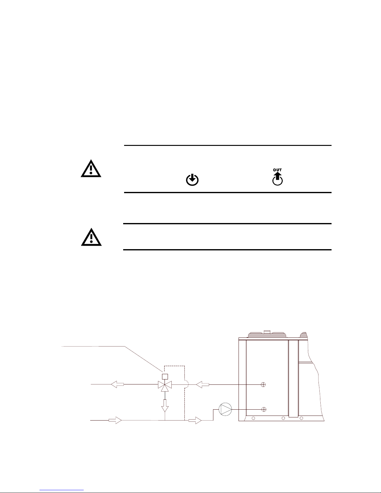
Blue Box - 43
4.7 ZETA 2002/DC HEAT RECOVERY EXCHANGER HYDRAULIC CONNECTIONS
For all units equipped with a recovery condenser, the relative hydraulic circuit connections are male threaded
steel pipes (the diameter depends on the unit's size)
The units are equipped with a probe that monitors the temperature of the water returning from the system. The
microprocessor controller enables recovery when necessary, disconnecting the fans, and restarting regular operation
once the water has reached the desired temperature.
If faults occur on the recovery condenser the microprocessor controller restarts the fans.
The calibration values of the thermostat and pressure switches are given in the relevant controller instruction
manual.
For units equipped with a recovery condenser:
It is mandatory to install a three-way modulating, valve with water temperature probe, on the inlet to the unit to ensure that, at steady state
conditions, the inlet water temperature is not less than 20 °C.
DIAGRAM WITH 3-WAY VALVE
Figure 9
3-way valve
Recovery
water outlet
Recovery
water inlet
The water inlet and outlet must be connected in the positions indicated
as labelled on the unit.
IN
ACQUA RECUPERO
RECOVERY WATER
Page 50
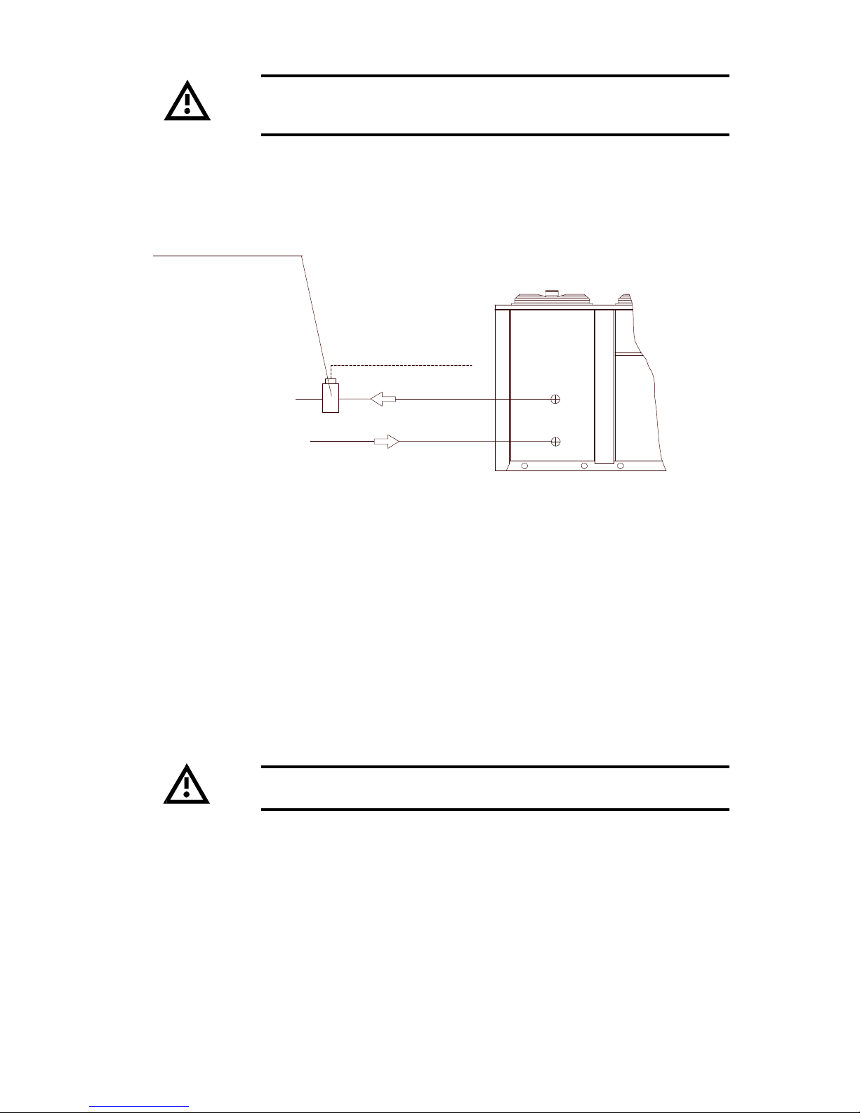
Blue Box - 44
Alternatively: a condensing pressure control valve for each refrigerant
circuit that ensures an average condensing temperature of at least 33
°C.
DIAGRAM WITH CONDENSING PRESSURE CONTROL VALVE
4.8 PRESSURE RELIEF VALVES
Pressure relief valves are fitted on the high pressure side and low pressure side of the refrigerant circuit. The
valves must be vented, to outdoors, through a vent pipe.
The vent pipe must be sized no smaller than the relief valve and it must not be supported from the valve.
This method ensures that the recovery unit is supplied with a flow that increases as the water temperature rises,
thus allowing the system to operating with optimum functional parameters at all times.
Figure 10
Ø
×
Condensing pressure control valve
Recovery water outlet
Recovery water inlet
To the refrigerant circuit
Caution: The relief valve must be directed into a safe zone where no
injuries can be caused to people.
Page 51
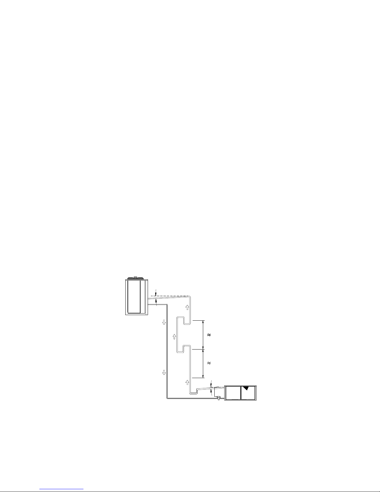
Blue Box - 45
4.9.1 Procedures to follow when sizing refrigerant lines
Depending on the relative position of the sections, there are certain procedures to follow when installing the
refrigerant line.
4.9 CONNECTIONS FOR VERSION /LE (MOTOCONDENSING UNIT)
/LE (condensing unit) versions must be connected to a remote evaporator by means of refrigerant lines.
For separate section type /LE versions, the route followed by refrigerant lines depends on the location of the
sections and the characteristics of the surrounding building structure.
Pipe runs should be as short as possible to limit the pressure drop and the refrigerant charge volume. The
maximum permissible pipeline length is 30 metres.
If this limits cannot be adhered to contact Blue Box for further information.
4.9.2 Evaporating section at lower level than condensing section:
a) The vertical riser must be equipped with siphons at least every 6 metres to facilitate the return of oil to the
compressor;
b) Make a collection pit on the suction line downstream of the thermostatic valve bulb;
c) Horizontal sections of the suction line should follow a grade of at least 1% to facilitate oil return to the
compressor (see above).
1 %
6 m
6 m
1 %
Evaporator
Figure 11
The diameter of pipes can be obtained from table 1, according to the selected model and length of connecting
pipes.
Page 52
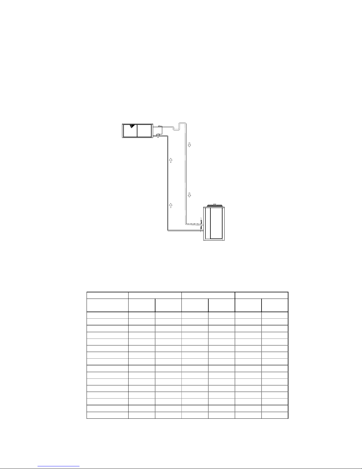
Blue Box - 46
4.9.3 Evaporating section positioned higher than the condensing unit section:
a) Form a siphon on the suction line,at the same height as the evaporator, to avoid drainage of liquid towards the
compressor when the unit is stopped.
b) Make a collection pit on the suction line, downstream from the thermostatic valve bulb, for the collection of
liquid refrigerant that can accumulate during unit shutdown. When the compressor restarts the refrigerant will
evaporate rapidly: it is advisable to create the accumulation pit well away from the bulb to avoid the risk of
affecting the operation of the thermostatic valve.
c) Horizontal sections of the suction line should follow a grade of at least 1% to facilitate oil return to the
compressor.
1 %
Evaporator
TABLE 1 - EXTERNAL PIPE DIAMENTERS FOR /LE VERSIONS
Figure 12
Distance [m]
MODEL Suction Liquid Suction Liquid Suction Liquid
ZETA 2002 [mm] [mm] [mm] [mm] [mm] [mm]
3.2 35 18 35 18 35 18
4.2 35 22 42 22 42 22
5.2 35 22 42 22 42 22
6.2 42 22 42 22 42 22
7.2 42 28 42 28 54 28
8.2 42 28 42 28 54 28
9.2 54 28 54 28 54 28
10.2 54 28 54 28 54 28
12.2 54 35 54 35 54 35
13.2 54 35 67 35 67 35
14.4 42 28 42 28 54 28
16.4 42 28 42 28 54 28
18.4 54 28 54 28 54 28
20.4 54 28 54 28 54 28
24.4 54 35 54 35 67 35
26.4 54 35 67 35 67 35
3010 20
Page 53
Blue Box - 47
4.10 WATER FLOW RATE TO EVAPORATOR
The nominal water flow rate is based on a 5 °C temperature difference between inlet and outlet in relation to the
supplied cooling capacity.
The maximum permissible flow rate is that which results in a temperature difference of 3 °C: higher flow rates will
lead to excessive pressure drops and could damage the evaporator.
The minimum permissible flow rate is that which results in a temperature difference of 8 °C or a pressure drop of
no less than 10 kPa: lower flow rates will lead to excessively low evaporation temperatures with consequent
tripping of safety devices and shutdown of the unit.
4.11 CHILLER WATER TEMPERATURE (summer cycle)
For the minimum water temperature at the evaporator outlet refer to section 4.14.
The maximum water temperature at the evaporator inlet is 20 °C. In the case of higher temperatures specific
solutions are necessary (dual circuits, three-way valves, by-pass, storage tanks): consult the Bluebox Engineering
Department to discuss the most suitable solution for your application.
4.12 HOT WATER TEMPERATURE (winter cycle)
The minimum water temperature at the condenser inlet, once the system is operating in steady state conditions,
must be no lower than 23 °C: lower values could result in operating anomalies of the compressor with the
consequent risk of compressor breakdown.
The maximum water temperature at the condenser outlet must be no higher than 48 °C. In the event of higher
temperatures the safety devices will trip causing the unit to shut down.
Warning: speed control calibration settings must not be altered. If it
proves necessary to alter speed calibration settings, this task must be
entrusted to a skilled engineer, who should refer to the attached instruction
sheet.
4.13 Ambient air temperature
- The units are designed and built to operate with ambient air temperatures within the limits shown on the
operating limits diagrams. Contact Bluebox if the unit is required to operate at different ambient temperatures.
- It should be noted that the performance of heat pump units decreases significantly at lower ambient temperatures.
- The units can be optionally equipped with an electric element for heating the evaporator. The heater cuts in,
when the machine is switched off, if the water temperature in the evaporator falls below the freeze protection
calibration temperature.
4.14 FAN SPEED CONTROL (optional)
If the unit is required to operate at ambient air temperatures less than 18 °C a fan speed controller must be
included. With fan speed control the unit can function correctly, at low ambient temperatures, by reducing the air
flow supplied to the condenser so that it operates within acceptable parameters.
This control is calibrated and tested in the factory.
Page 54
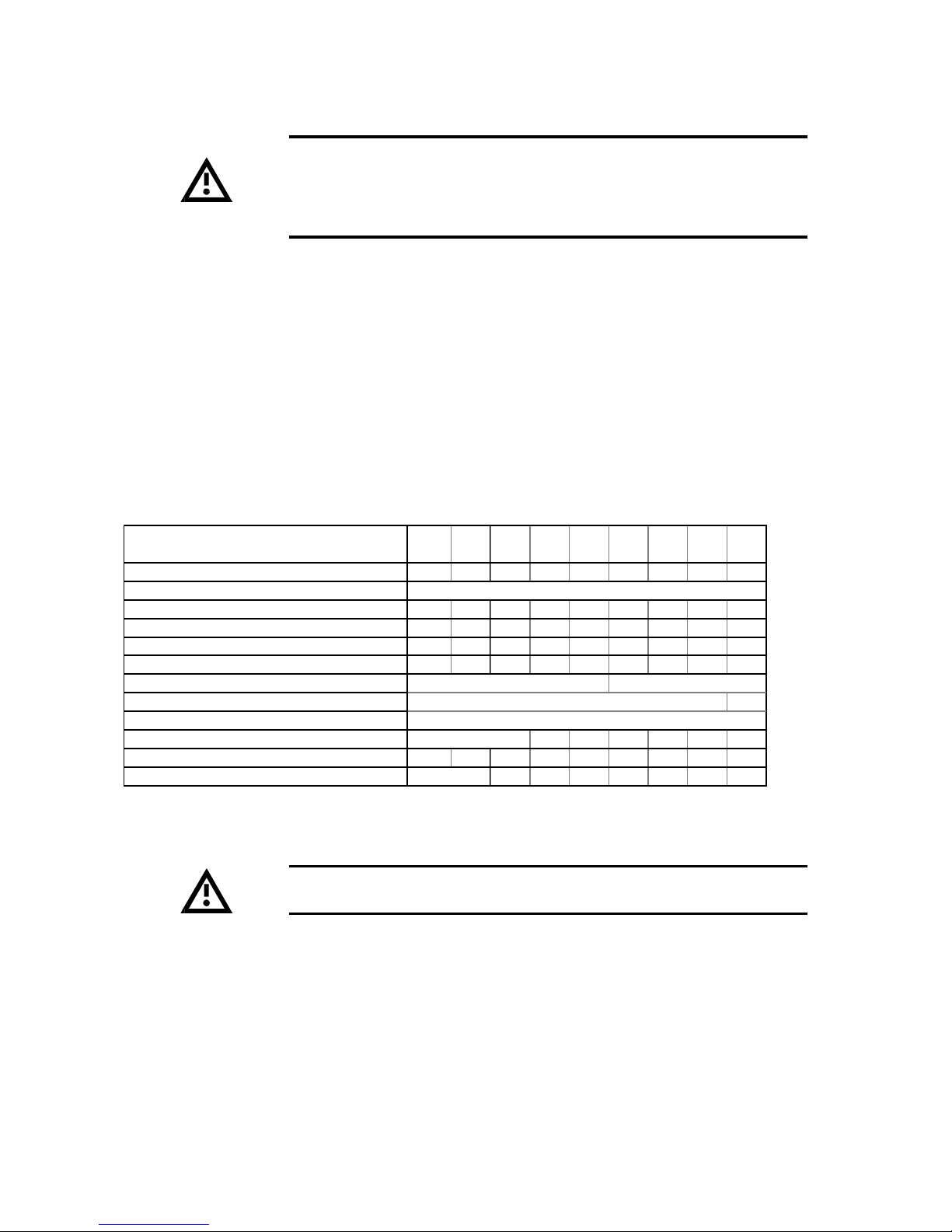
Blue Box - 48
With temperatures lower than those shown in the operating limit diagrams, the hydraulic circuit should be filled
with a suitable water and antifreeze solution. In such cases the service thermostat and the freeze protection
thermostat must be reset:
These calibrations are normally set in the factory.
The ethylene glycol percentage must be selected in relation to the required chilled water temperature.
See Table 2.
Units from the normal production range are not designed to operate with
lower chilled water temperatures, at the evaporator outlet, than those
indicated in the operating limit diagrams. To operate outside this limit
the unit may require structural modifications. If this should become
necessary Bluebox.
4.15 OPERATION WITH LOW TEMPERATURE CHILLED WATER AT EVAPORATOR
TABLE 2 - FREEZING POINT FOR WATER-ANTIFREEZE MIXTURES
In the case of ST versions with a glycol content greater than 30% pumps
with special seals must be specified at the time of the order.
LIQUID OUTLET TEMPERATURE
OR MINIMUM AMBIENT TEMPERATURE (°C)
FREEZING POINT (°C) -5° -10° -15° -20° -25° -30° -35° -40° -45°
ANTIFREEZE
ETHYLENE GLYCOL 6 22 30 36 41 46 50 53 56
PROPYLENE GLYCOL 15 25 33 39 44 48 51 54 57
METHANOL 8 14 20 26 30 34 38 41 45
CALCIUM CHLORIDE 9 14 18 21 24 26 27 28 30
TEMPER -20
TEMPER -40 --TEMPER -60
TIFOXITE 50 60 63 69 73 --FREEZIUM 10 20 25 30 34 37 40 43 45
PEKASOL 50 59 68 75 81 86 90 ---
-30° -35°+0° -5° -10° -15° -40°
% BY WEIGHT
40
50
T -20°C
T -40°C
T -60°C
---
-20° -25°
Page 55
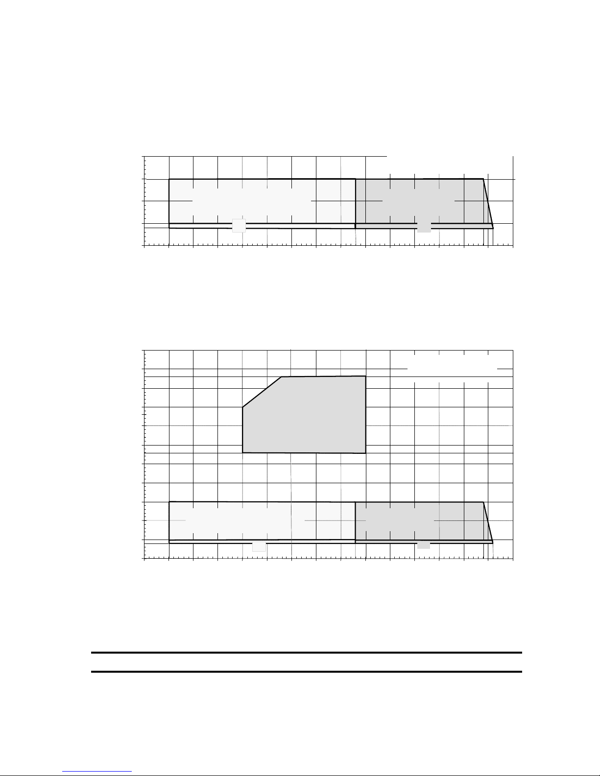
Blue Box - 49
OPERATING LIMITS
ZETA 2002 - R22 refrigerant
User water outlet temperature [°C]User water outlet temperature [°C]
Ambient air temperature [°C]
Ambient air temperature [°C]
0
5
10
15
20
-25 -20 -15 -10 -5 0 5 10 15 20 25 30 35 40 45 50
Refrigeratore
Chiller
Raffreddamento
Cooling
Con dispositivi opzionali per basse
temperature dell’aria esterna.
With low ambient temperature kit.
(1)
(1)
55
-25 -20 -15 -10 -5 0 10 20 25 30 35 40 45 50
0
5
10
15
20
25
30
35
40
45
50
Pompa di calore
Heat pump
Riscaldamento
Heating
Raffreddamento
Cooling
Con dispositivi opzionali per basse
temperature dell’aria esterna.
With low ambient temperature kit.
(1)
Riscaldamento
Heating
Riscaldamento
Heating
The water temperature rise for all versions must be between 3 °C (min) and 8 °C (max)
(1) Working limits of units with 2 compressors
Page 56
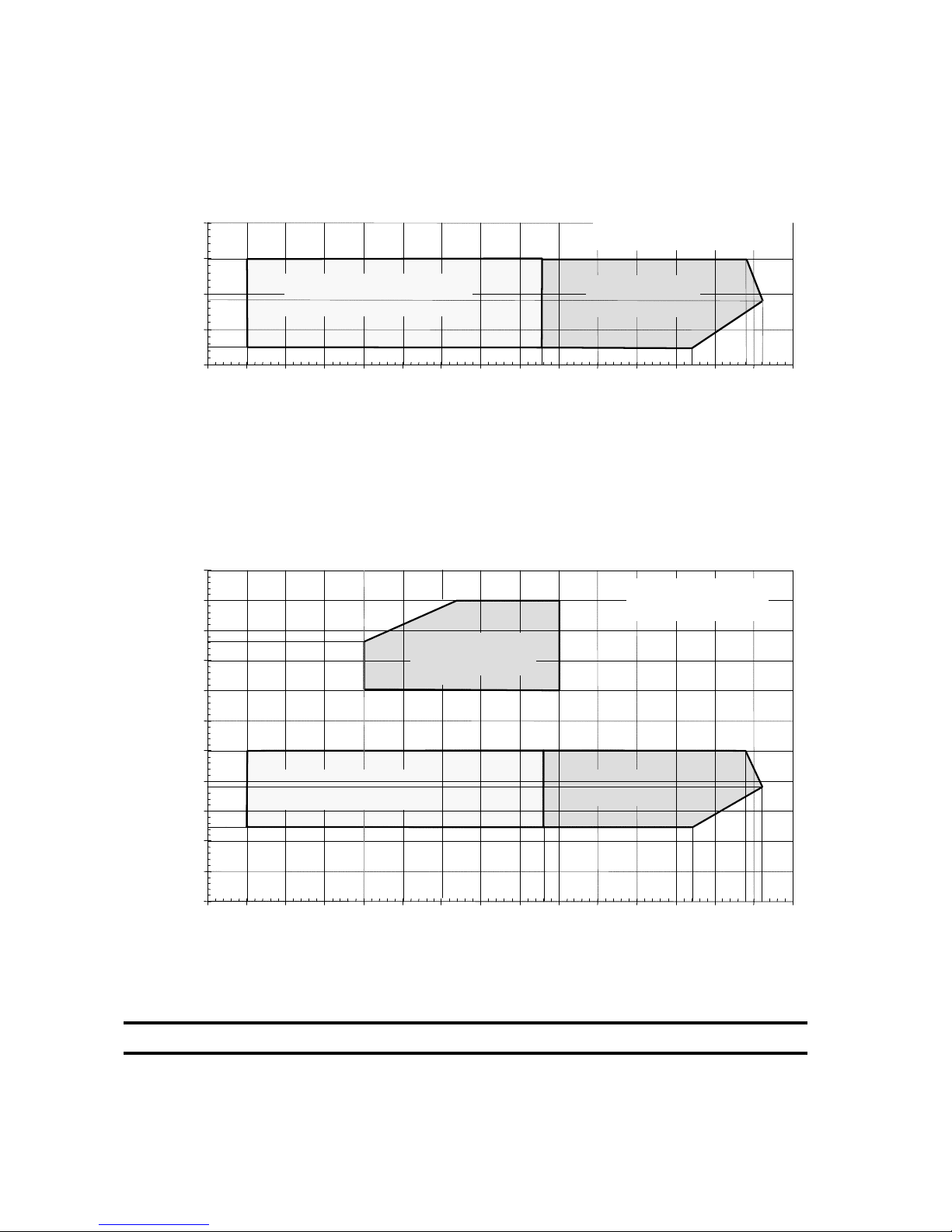
Blue Box - 50
OPERATING LIMITS
ZETA 2002/LE - R22 refrigerant
Evaporation temperature [°C]Evaporation temperature [°C]
Condensation temperature [°C]
Ambient air temperature [°C]
Ambient air temperature [°C]
-20
-10
0
10
20
-25 -20 -15 -10 -5 0 5 10 15 20 25 30 35 40 45 50
Refrigeratore
Chiller
Raffreddamento
Cooling
Con dispositivi opzionali per basse
temperature dell’aria esterna.
With low ambient temperature kit.
70
-25 -20 -15 -10 -5 0 5 10 15 20 25 30 35 40 45 50
-30
-20
-10
0
10
20
30
40
50
60
Pompa di calore
Heat pump
Riscaldamento
Heating
Raffreddamento
Cooling
Con dispositivi opzionali per basse
temperature dell’aria esterna.
With
low
ambient temperature kit.
The water temperature rise for all versions must be between 3 °C (min) and 8 °C (max)
Page 57
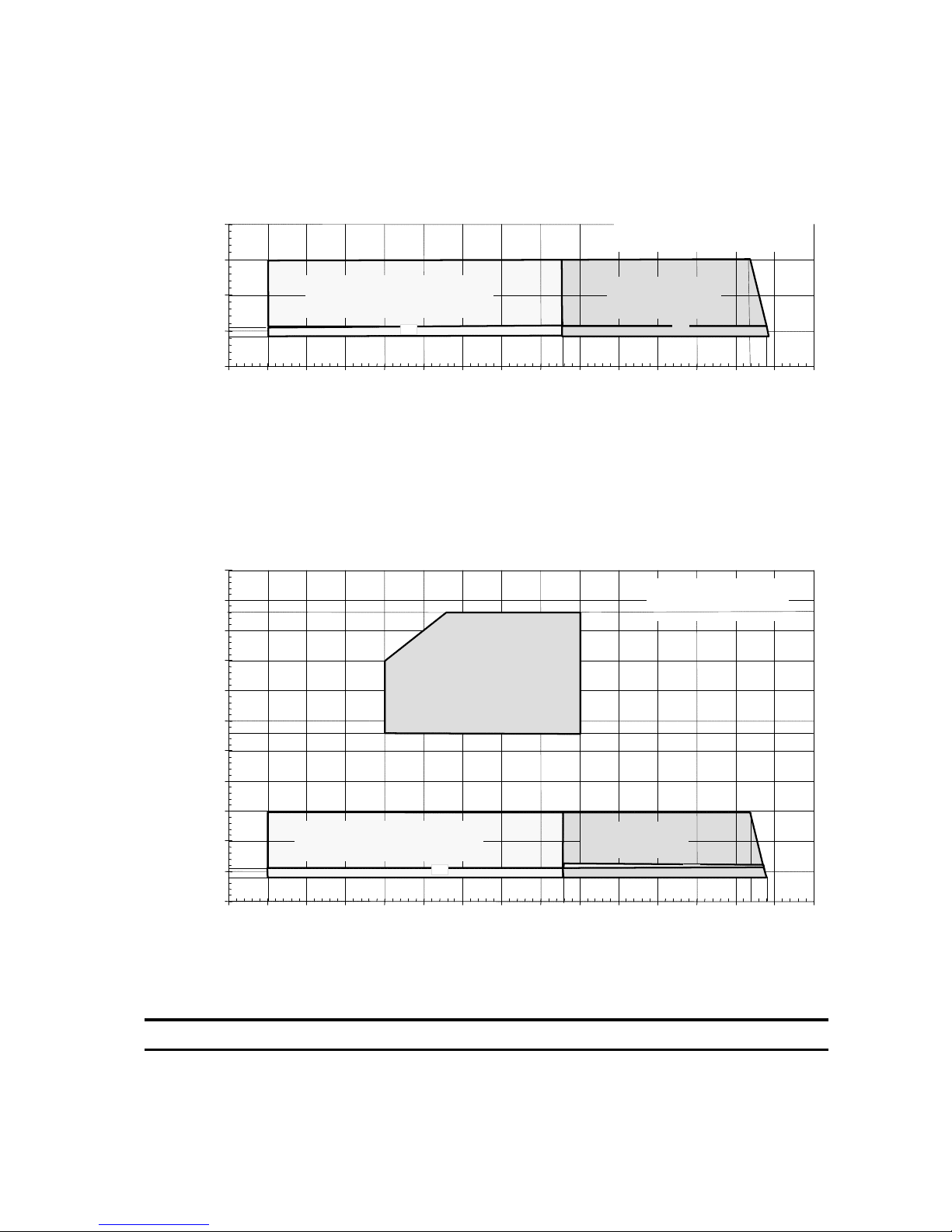
Blue Box - 51
The water temperature rise for all versions must be between 3 °C (min) and 8 °C (max)
OPERATING LIMITS
ZETA 2002 - R407C refrigerant
User water outlet temperature [°C]User water outlet temperature [°C]
Ambient air temperature [°C]
Ambient air temperature [°C]
(1) Working limits of units with 2 compressors
0
5
10
15
20
-25 -20 -15 -10 -5 0 5 10 15 20 25 30 35 40 45 50
Refrigeratore
Chiller
Raffreddamento
Cooling
Con dispositivi opzionali per basse
temperature dell’aria esterna.
With low ambient temperature kit.
(1)
(1)
55
-25 -20 -15 -10 -5 0 5 10 15 20 25 30 35 40 45 50
0
5
10
15
20
25
30
35
40
45
50
Pompa di calore
Heat pump
Raffreddamento
Cooling
Con dispositivi opzionali per basse
temperature dell’aria esterna.
With low ambient temperature kit.
Riscaldamento
Heating
Page 58
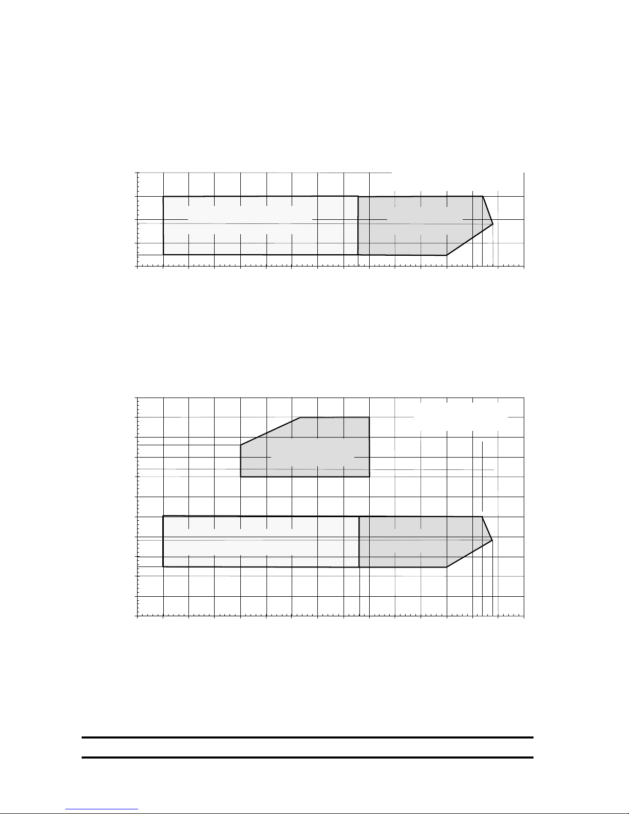
Blue Box - 52
OPERATING LIMITS
ZETA 2002/LE - R407C refrigerant
Evaporation temperature [°C]Evaporation temperature [°C]
Condensation temperature [°C]
Ambient air temperature [°C]
Ambient air temperature [°C]
-20
-10
0
10
20
-25 -20 -15 -10 -5 0 5 10 15 20 25 30 35 40 45 50
Refrigeratore
Chiller
Raffreddamento
Cooling
Con dispositivi opzionali per basse
temperature dell’aria esterna.
With low ambient temperature kit.
70
-25 -20 -15 -10 -5 0 5 10 15 20 25 30 35 40 45 50
-30
-20
-10
0
10
20
30
40
50
60
Pompa di calore
Heat pump
Riscaldamento
Heating
Raffreddamento
Cooling
Con dispositivi opzionali per basse
temperature dell’aria esterna.
With low ambient temperature kit.
The water temperature rise for all versions must be between 3 °C (min) and 8 °C (max)
Page 59
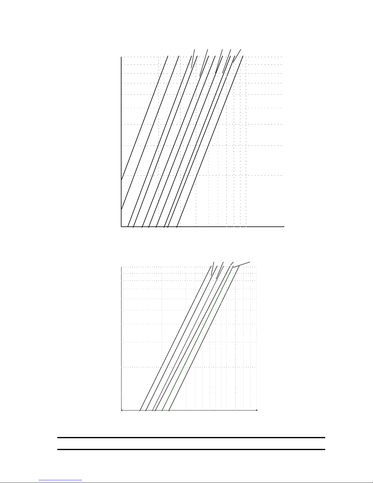
Blue Box - 53
EVAPORATOR PRESSURE DROP
4 5
2
20
30
50
60
70
80
90
100
40
1
3
6
10
9.2
12.2
5.2
7 9810
8.2
3.2
13.2
7.2
4.2
6.2
10.2
Portata acqua [ l/s]
Water flow
Perdite di carico [kPa]
Pressure drop
10
2
20
30
50
60
70
80
90
100
40
6
8
10
18.4
26.4
14.4
4
12
16.4
7 9
24.4
11
14 1816
20
20.4
Portata acqua [l/s]
Water flow
Perdite di carico [kpa]
Pressure drop
The water temperature rise for all versions must be between 3 °C (min) and 8 °C (max)
Page 60
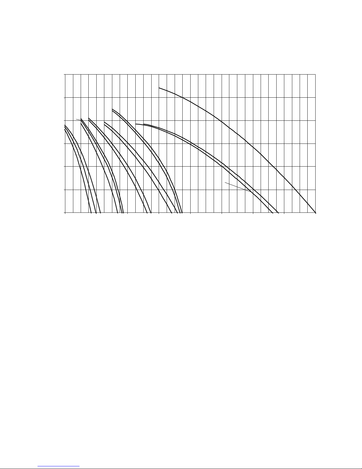
Blue Box - 54
PUMPS AVAILABLE PRESSURE - MODEL ZETA 2002 /ST 2PS
0
50
100
150
200
250
300
1 3 5 7 9 11 13 15 17
Portata acqua [l/s]
Water flow
Prevalenza utile [kPa]
Available pressure
26.4
16.4
9.2
8.2
3.2
6.2
12.2
18.4-20.4
24.4
5.2
7.2
13.2
4.2
10.2
14.4
AVAILABLE PRESSURE
Page 61
Blue Box - 55
Electrical connections must be made in accordance with the information given on the electrical drawing attached
to the unit and in compliance with the applicable local regulations.
An Earth (ground) connection is compulsory. The installer must connect the earth cable with a dedicated terminal
on the earth bar in the electrical board (refer to the illustration on the following page) labelled PE.
It must be verified that the electrical supply corresponds to the unit electrical nominal data (tension, phases,
frequency) indicated on the label on the front panel of the unit.
Line voltage fluctuations must not be more than ±5% of the nominal value, while the voltage unbalance between
one phase and another must not exceed 2%. If these tolerances are not possible contact Blue Box to provide the
necessary devices.
Check that the line is connected with the correct phase sequence.
The cable inlet point is created by drilling a hole in the side or base of the electrical enclosure, depending on the
model.
The control circuit is derived from the power supply through a transformer located inside the electrical panel.
The control circuit is protected by fuses.
4.16 ELECTRICAL CONNECTIONS
4.16.1 General
Before any operation on the electrical section, be sure that the electric
supply is disconnected.
Power cable and line protection must be sized according to the
specification indicated on the wiring diagram and the documents supplied
with the unit.
The electrical supply must be within the limits shown. If this is not the
case the warranty will be terminated immediately.
Electrical cable anchorage: anchor the electrical power cables with fixing
systems able to withstand pulling and torsional stress.
The crankcase heaters must be connected at least 12 hours before starting
the unit; the heaters are automatically connected when the main
disconnect switch is set to the ON position.
Page 62
Blue Box - 56
4.17 MICROPROCESSOR CONTROLLERS
Chillers in the ZETA 2002 series with 2 scroll compressors, models from 3.2 to 13.2, are equipped with the
mCHILLER type microprocessor controller.
Chillers in the ZETA 2002 series with 4 scroll compressors, models from 14.4 to 26.4, are equipped with the pCO2
microprocessor controller.
4.16.5 Circulating pump electrical connections
The external interlocks of unit must close for the unit to operate. The normally open external water circulating
pump contactor terminals must be wired in series with terminals 1 and 2, on the unit control panel, to ensure that
the chiller can only start after the pump is in operation.
In ST units external enabling contacts 1-2 must be jumpered (unless they are required for system functions).
Turn on the pump before the unit starts and stop it after the unit has
stopped (recommended time delay: 60 sec.).
4.16.3 Potential free contacts
The following potential free contacts are available:
- 1 potential free contact for general alarm (terminals 100 - 101 - 102)
- 1 potential free contact for each compressor (option)
- 1 contact for each pair of fans (option)
- 1 contact for each pump (option - ST models)
4.16.4 Flow switch electrical connections
Flow switch electrical connections (see paragraph 4.4 ) must be connected to terminal 1-14 for chiller units.
4.16.2 Power supply to crankcase heaters
1) Close the main disconnect switch by turning it from position “0” to position “1”
2) Check that the word “OFF” is shown on the display
3) Ensure that the unit is in “OFF” status and that the external enabling contact is open
4) After a few moments, if the phase sequence is incorrect the alarm “INCORRECT PHASE SEQUENCE” will be
displayed (4-compressor models from 14.4 to 26.4 only, with pCO2 controller). In this case invert the connections
of two of the power line phase wires.
5) Leave the unit in this condition for at least 12 hours to allow the crankcase heaters to perform their function
Page 63

Blue Box - 57
4.17.2 RS485 serial interface (optional)
All units can be equipped with a serial interface board for supervision or remote diagnostics
functions by means of a computer.
The serial interface board plugs into a dedicated slot on the connection board.
Connection to the supervision or remote diagnostics serial line is executed in compliance with standard RS485
and is achieved by means of the serial interface boards.
Models from 3.2 to 13.2 with two scroll compressors and µchiller controller
When the serial interface board is inserted the Carel communications protocol is available.
A conversion gateway is required for the Modbus-jbus and BacNet protocols.
Models from 14.4 to 26.4 with 4 scroll compressors and pCO2 controller
When the serial interface board is inserted the following communications protocols are available: Carel, Modbusjbus, BacNet. If a connection is to be made with networks that utilise the Lon-Talk protocol, a dedicated board
must be installed.
In this case, a conversion gateway is not required.
4.17.1 Microprocessor controller for /LE and HP/LE versions
- Versions ZETA 2002 /LE and ZETA 2002 HP/LE with two compressors are equipped with an mchiller controller.
- Versions ZETA 2002 /LE and ZETA 2002 HP/LE with four compressors do not have an integral controller and
therefore an external controller, or thermostats, must be connected to the auxiliary terminals 1-21, 1-31, 1-41
and 1-51.
Consult the electrical diagram attached to the unit.
Page 64
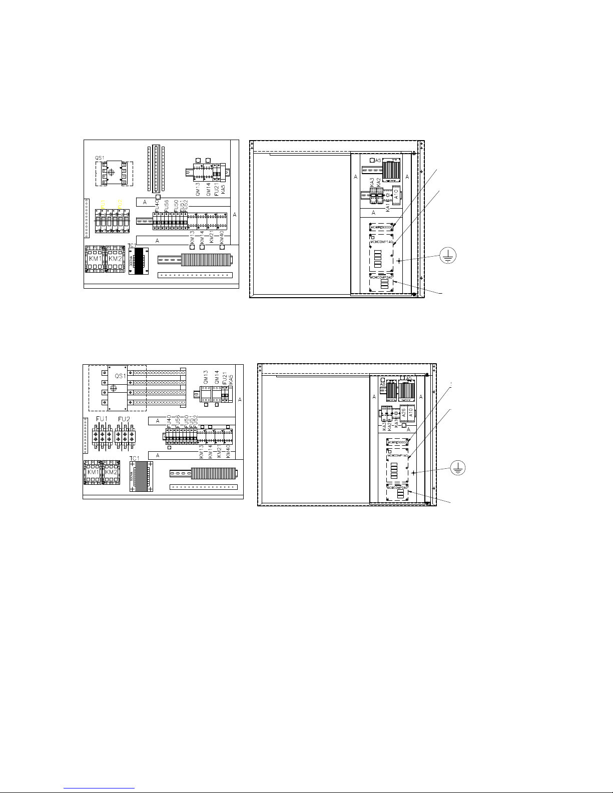
Blue Box - 58
ELECTRICAL PANEL LAY OUT
Unit with 2 compressors - µchiller controller
ZETA 2002 - Models 9.2 - 13.2
ZETA 2002 - Models 3.2 - 8.2
A10 ON/OFF CONTROL CIRCUIT BOARD
A5 SPEED REGULATOR
A8 SPEED REGULATOR
FU1 COMPRESSOR 1 FUSES
FU2 COMPRESSOR 2 FUSES
FU21 FAN UNIT FUSES
FU21 FAN UNIT FUSES
FU40 HEATER FUSES
FU50 AUXILIARY TRANSFORMER FUSES
FU51 CONTROL CIRCUITS FUSE
FU52 CONTROLLER FUSE
FU56 PHASE SEQUENCE RELAY FUSES
KA1 POWER “ON” RELAY
KA2 FAN UNIT ALARMS RELAY
KA3 HP RELAY
KA5 PHASE SEQUENCE RELAY
KM1 COMPRESSOR 1 CONTACTOR
KM13 PUMP 1 CONTACTOR
KM14 PUMP 2 CONTACTOR
KM2 COMPRESSOR 2 CONTACTOR
KM21 FAN UNITS CONTACTOR
KM40 EVAPORATOR HEATER CONTACTOR
QM13 PUMP 1 MOTOR OVERLOAD CUT-OUT
QM14 PUMP 2 MOTOR OVERLOAD CUT-OUT
QS1 MAIN POWER DISCONNECT SWITCH
TC1 CONTROL CIRCUITS TRANSFORMER
KEY TO ELECTRICAL COMPONENT PART NUMBERS
REMOTE CONTROL CARD OPTIONAL
MICRO CHILLER CARD 1 COMPRESSOR
POSITION OF CONNECTION
TO EARTH TERMINAL
MICRO CHILLER CARD 2 COMPRESSOR
MICRO CHILLER CARD 1 COMPRESSOR
POSITION OF CONNECTION
TO EARTH TERMINAL
MICRO CHILLER CARD 2 COMPRESSOR
REMOTE CONTROL CARD OPTIONAL
Page 65
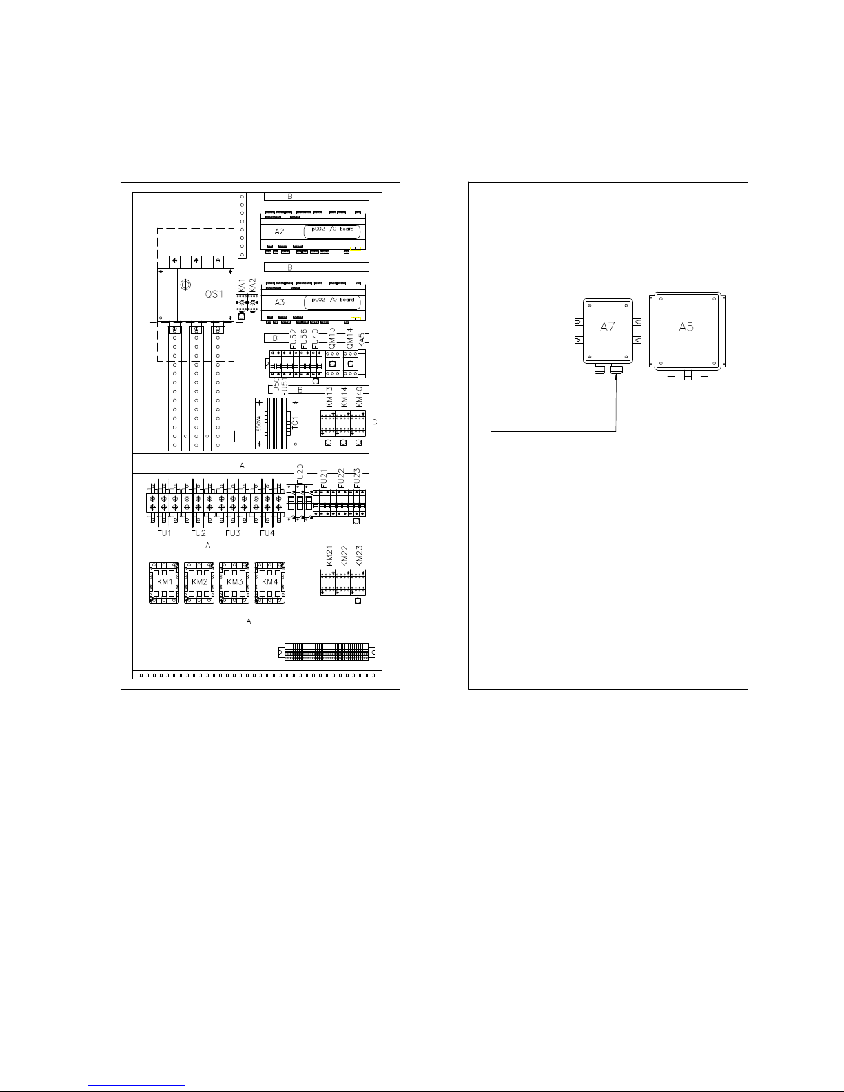
Blue Box - 59
KEY TO ELECTRICAL COMPONENT PART NUMBERS
ELECTRICAL PANEL LAY OUT
Unit with 4 compressors - pCO2 controller
ZETA 2002 - Models 14.4 - 26.4
A2 CONTROL BOARD
A3 2-COMPRESSOR EXPANSION BOARD
A5 SPEED REGULATOR
A7 RGF EXPANSION MODULE, UNIT /LE
FU1 COMPRESSOR 1 FUSES
FU2 COMPRESSOR 2 FUSES
FU20 RGF FUSES
FU21 FAN UNIT FUSES
FU22 FUSES - FAN UNITS 2
FU23 FUSES - FAN UNITS 3
FU3 FUSES - COMPRESSOR 3
FU4 FUSES - COMPRESSOR 4
FU40 FUSES- HEATERS
FU50 FUSES - AUXILIARY TRANSFORMER
FU51 CONTROL CIRCUITS FUSE
FU52 CONTROLLER FUSE
FU56 PHASE SEQUENCE RELAY FUSES
KA1 POWER “ON” RELAY
KA2 FAN UNIT ALARMS RELAY
KA5 PHASE SEQUENCE RELAY
KM1 COMPRESSOR 1 CONTACTOR
KM13 PUMP 1 CONTACTOR
KM14 PUMP 2 CONTACTOR
KM2 COMPRESSOR 2 CONTACTOR
KM21 FAN UNITS CONTACTOR
KM22 FAN UNIT 2 CONTACTOR
KM23 FAN UNIT 3 CONTACTOR
KM3 COMPRESSOR 3 CONTACTOR
KM4 COMPRESSOR 4 CONTACTOR
KM40 EVAPORATOR HEATER CONTACTOR
QM13 PUMP 1 MOTOR OVERLOAD CUT-OUT
QM14 PUMP 2 MOTOR OVERLOAD CUT-OUT
QS1 MAIN POWER DISCONNECT SWITCH
TC1 CONTROL CIRCUITS TRANSFORMER
RGF EXPANSION
MODULE FOR LE UNIT
Page 66
Blue Box - 60
5. START-UP
5.1 PRELIMINARY CHECKS
- Check that the electrical connections have been made correctly, and that all terminals are well tightened.
- Check that the voltage on the RST terminals is 400 V ± 5% (or the unit’s rated value, in the event of units
supplied to run on non-standard power supplies). If the mains voltage is subject to frequent fluctuations, consult
our Engineering Department to discuss the necessary protection systems.
- Check that the display shows the gas pressure in the refrigerant circuit (4-compressor models only).
- Inspect the unit for refrigerant leaks using a leak detector if necessary.
- Check that the crankcase heaters are correctly supplied with power.
- Verify that heaters are working correctly: after the warm up period the crankcase must be warm to the touch
and must have at least a temperature 10 - 15 °C higher than ambient temperature.
- Check that all hydraulic connections are correctly installed and all indications on unit labels are observed.
- Check that the hydraulic system has been vent to eliminate any air remaining; charge it gradually and open the
vent devices on the upper part, provided at the care of the installer together with an expansion tank of a proper
size.
The heaters must be connected at least 12 hours before starting the unit;
the heaters are automatically connected when the main disconnect switch
is set to the ON position.
Significant leakage of R407C refrigerant in the gaseous state will alter
the percentages of the remaining mixture with consequent fall-off of
performance.
Warning: before starting up the unit check that all the closing panels are
in position and secured with the relative screws.
Page 67
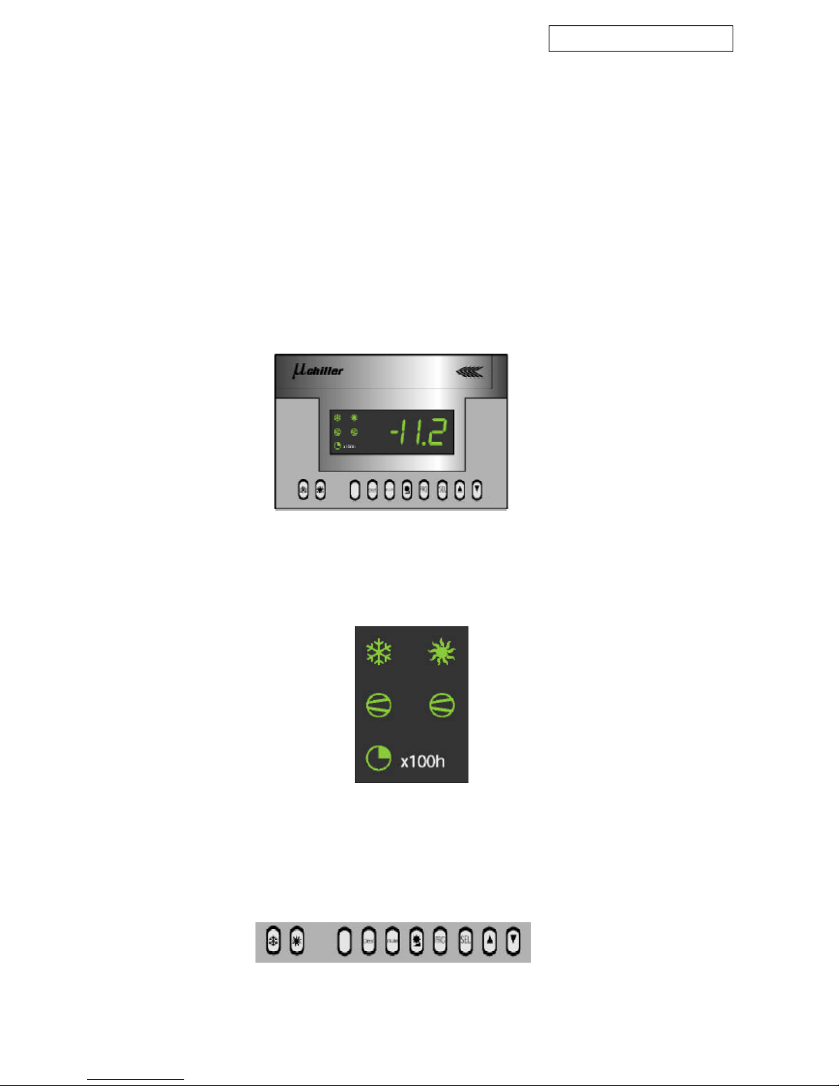
Models 3.2 - 13.2, µchiller control
Blue Box - Page 61
Figure 13
Figure 15
Figure 14
6 UNIT WITH m CHILLER MICROPROCESSOR (models from 3.2 to 13.2)
6.1 INTRODUCTION
“µchiller” is an electronic microprocessor system designed to control all the unit’s functions.
The terminal is equipped with five LEDs indicating the operating status of the machine (summer/winter), the
compressor status (On/Off) and indication of the compressors/pump hour counter after the first 100 hours of
operation. An internal beeper (which can be inhibited by means of a microswitch or a parameter) sounds to warn
of machine operating anomalies.
6.1.1 Display
The display comprises three digits with automatic display of the decimal point. During normal operation the
display shows the value of the evaporator inlet water temperature.
“µchiller” can be connected to a computer, by means of an optional electronic board, making available remote
supervision and telediagnostic services for complete management, supervision and diagnostics of the systems
from a remote location.
6.1.2 Machine status information
Machine status information is shown by five LEDs on the remote control display (figure 14).
6.1.3 Keypad
The keypad allows machine operating parameters to be programmed. The wall-mounted version features an
extended number of keys to facilitate use. The function of each key is illustrated on the following pages.
Page 68
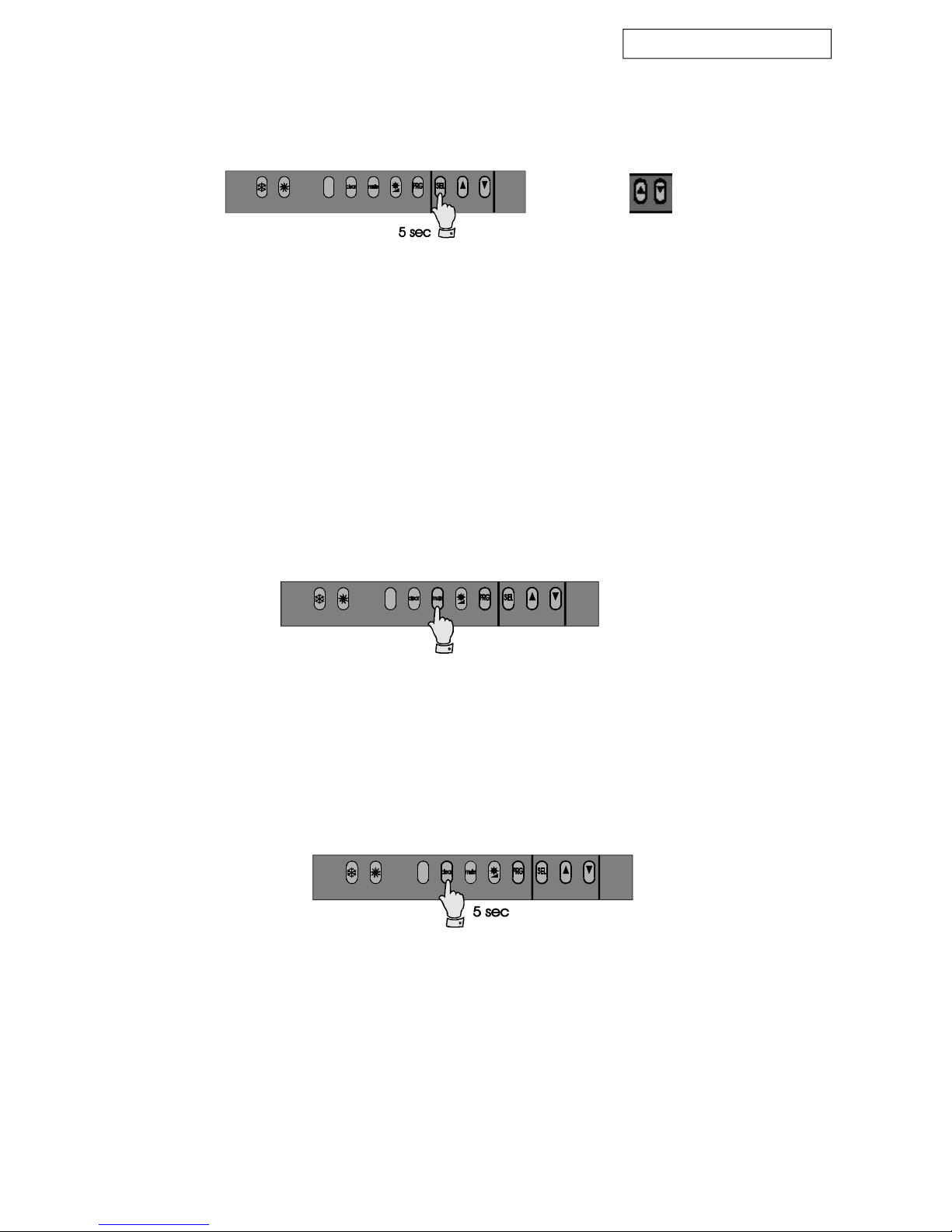
Models 3.2 - 13.2, µchiller control
Blue Box - Page 62
Figure 16
Figure 17
Figure 18
6.1.4 Control and display screens
Method of accessing the set-point and main machine control parameters.
Pressing the keys marked with an up or down arrow allows you to scroll through the parameters. The SEL key is
pressed again to display the value of the selected parameter, with the facility to edit the value if required using
the Up or Down keys. The PRG key is pressed to store changed values and to stop the procedure, while pressing
the SEL key returns you to the parameter selection menu. If no keys are pressed, in an interval of 10 seconds,
during parameter editing the display starts flashing. If no keys have been pressed within 60 seconds, after
activating the programming procedure, the controller will return to the temperature display without saving any
changes that have been made. This procedure is useful if it proves unnecessary to alter any parameters.
6.1.5 Muting the BUZZER
Press the MUTE key to silence the buzzer if it is currently sounding.
6.1.6 ALARMS reset
Pressing the Up or Down keys for more than 5 seconds cancels any alarms currently in the memory (manual
reset), clear the associated message from the display and deactivate the alarm relay. In wall mounted models this
function is obtained by pressing the CLEAR key for 5 seconds.
Parameter
scroll keys
Page 69
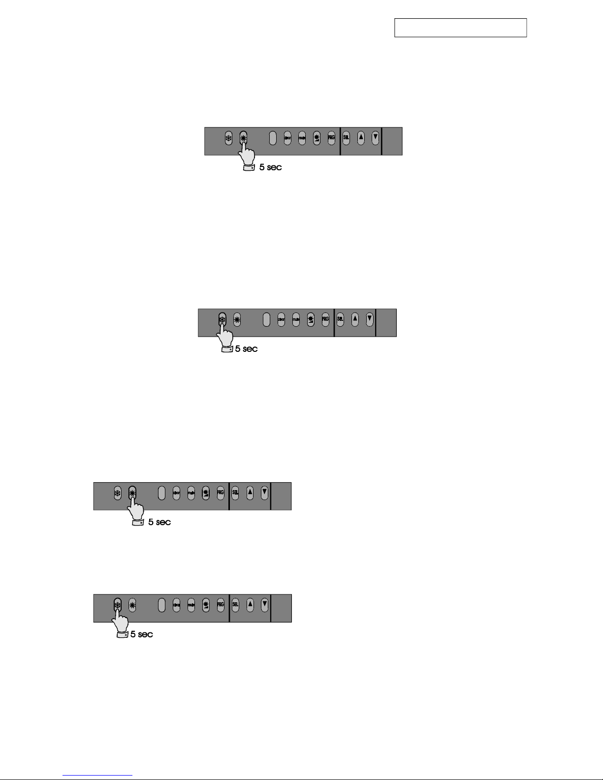
Models 3.2 - 13.2, µchiller control
Blue Box - Page 63
Figure 19
Figure 20
Figure 21
Figure 22
6.1.7 Activation/deactivation of COOLING operation (summer mode)
Pressing the key for more than 5 seconds activates or deactivates the summer operating mode (refer also to
parameter P6). It is not possible to switch directly from Winter mode to Summer mode without first deactivating
Winter mode. If the machine was previously running in Winter mode pressing this key will have no effect.
6.1.9 Switching off the machine (stand by)
To switch off the machine deactivate both Summer and Winter modes.
Switch off the unit when working in cooling mode
(Summer).
Switch off the unit when working in heating mode
(Winter).
6.1.8 Activation/deactivation of HEATING mode (winter mode)
Pressing the key for more than 5 seconds activates or deactivates the winter operating mode. It is not possible to
switch directly from Summer mode to Winter mode. If the machine was previously running in Summer mode
pressing this key will have no effect - Summer mode must be deactivated before the change can be made.
Page 70
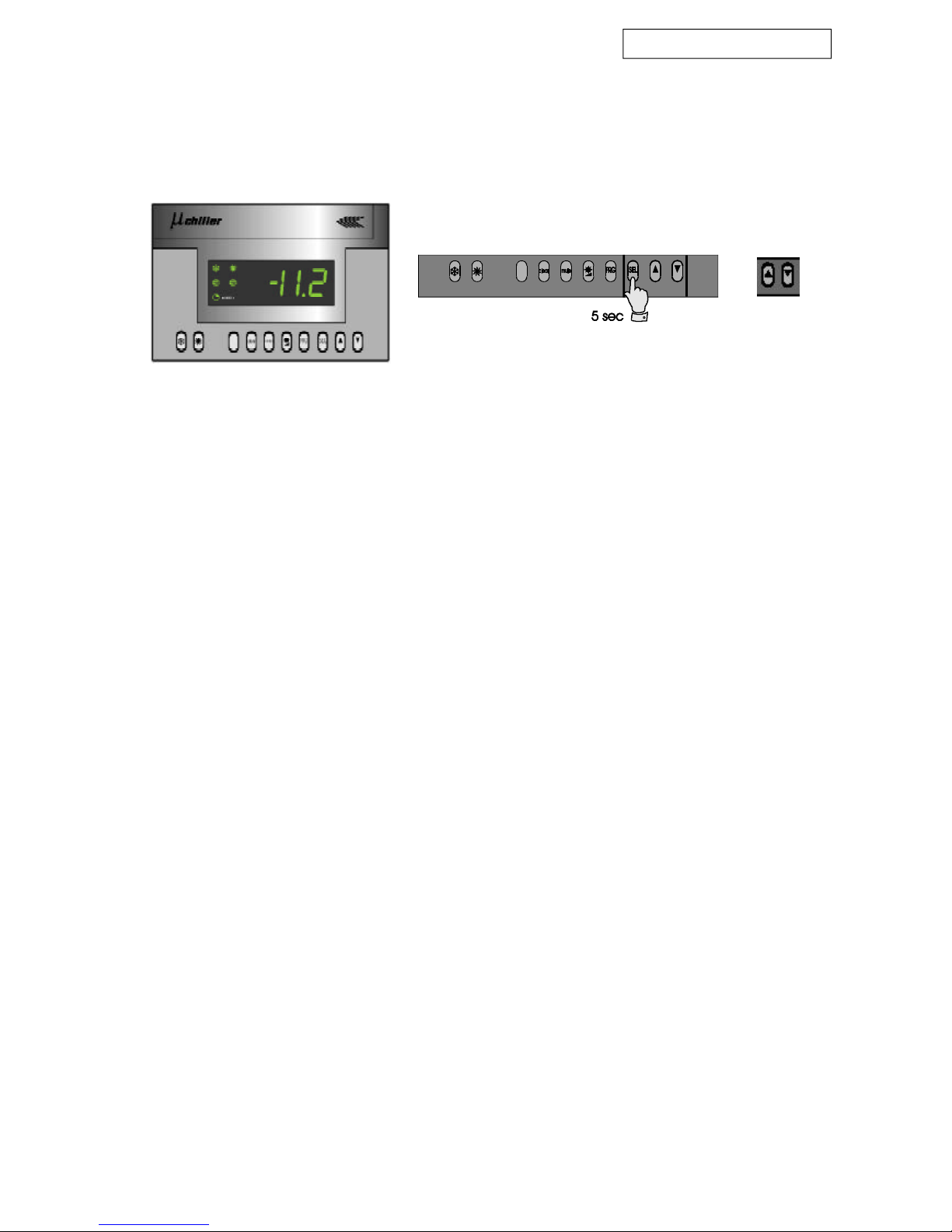
Models 3.2 - 13.2, µchiller control
Blue Box - Page 64
Parameter scroll
keys
6.1.11 Defrosting (heat pump mode only)
During winter heat pump mode operation the finned coil of the air cooled condenser functions as an evaporator,
cooling and dehumidifying ambient air.
During heat pump operation, the evaporation pressure is monitored to prevent it from falling below a preset
value. The evaporation control is active only during heating mode operation.
Depending on the ambient air temperature and humidity conditions, condensate or frost will tend to form,
consequently obstructing the free passage of air and causing thermal insulation. The frost that builds up on the
coil obstructs the passage of air and reduces the available heat exchange surface area (and thus the thermal
efficiency) and can damage the heat exchanger.
Defrosting is the procedure that eliminates the ice that has formed on the evaporator coil during heat pump mode
operation of an air/water unit.
Defrosting is performed simultaneously for the entire unit.
All heat pump versions are equipped with a control that activates an automatic coil defrost cycle when necessary.
After starting however, the first defrost cycle will be started after a preset minimum operating time to allow the
formation of sufficient thermal inertia to allow the cycle to be completed successfully.
Defrost cycle activation is based on the detection of a low suction pressure value due to insufficient heat exchange
between the evaporator and the air due to the formation of a layer of ice, which exerts a thermal insulation
effect. For a defrost cycle to be able to start a suction pressure of at least one of the currently operating compressors
must remain below the pressure set for the defrost cycle trip signal for a preset time interval.
Before starting to defrost the coils, all the compressors are started, after which the unit reverses its operation from
heat pump to chiller mode.
When the cycle is reversed the fans stop and the compressors force hot gas into the coil.
A pressure switch on the high pressure circuit maintains the discharge gas pressure below the defrost end value.
To maintain the pressure lower than the defrost end pressure the pressure switch activates the fans.
To reduce the air flow and obtain more efficient heating of the outer part of the coil, the pressure switch signal
causes the fans to rotate in reverse.
When the defrost end temperature is reached, as measured by a thermostat with a probe located in the lower
part of the coil, the pressure switch allows the discharge pressure to reach the defrost end pressure.
When the defrost end pressure has been reached, the controller reverses the unit from chiller mode to heat pump
mode, thereby terminating the defrost procedure.
Even though in certain conditions the surface temperature of the coil and the condensation pressure fail to reach
the defrost values within the preset time limit, the defrost cycle is forcibly terminated as though the defrost end
signal were present. The controller restarts the fans, and when the pressure lowers again to the preset value, it
reverses the unit’s operating mode again.
If the defrost cycle is forcibly interrupted, with the timeout signal, a message is displayed on the controller,
although no controller functions are activated.
The defrost timeout alarm is automatically cleared from the active alarms menus when a defrost cycle terminates
Figure 23
6.1.10 Inlet water temperature control:
To edit the operating values (within the operating limits) hold down the SEL button for 5 seconds. When it flashes
use the Up or Down arrow keys to enter the required inlet water temperature on the display. Confirm the value
you have just entered by pressing the SEL button again (figure 23).
Page 71
Models 3.2 - 13.2, µchiller control
Blue Box - Page 65
If the unit fails to start: do not change internal electrical connections on
penalty of immediate invalidation of the warranty.
Warning: The operating mode changeover should only be seasonal.
Frequent changeover from summer to winter operating mode and viceversa could cause damage to the compressors.
Electronic components of the microprocessor may be damaged at
temperatures below - 20 °C.
During idle periods do not disconnect the unit from the power supply (the
compressor crankcase heaters must remain switched on). Disconnect the
unit from the power supply only in the event of prolonged disuse (e.g.
seasonal shutdowns). For temporary shutdown of the unit refer to the
guide lines given in the specific headings of this manual.
normally because the defrost end pressure has been reached. In any event, the alarms historical file will contain
a record of all defrost cycles that were terminated forcibly due to a timeout intervention.
Consecutive defrost cycles must be at least 30 minutes apart. If the forced defrost signal persists, inform the
Service organisation.
Page 72
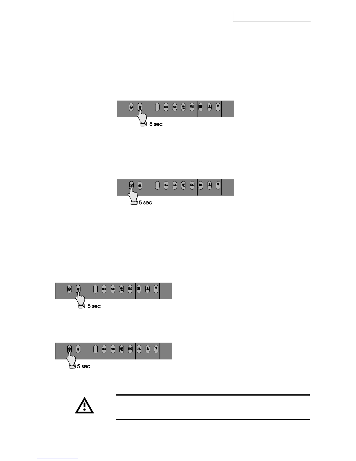
Models 3.2 - 13.2, µchiller control
Blue Box - Page 66
Figure 24
Figure 25
Figure 27
Figure 26
6.2 STARTING THE UNIT
The ZETA 2002 unit is equipped, as standard, with direct keypad control.
Optionally the unit can be equipped to operate via a remote permissive (e.g. a clock, etc.). The remote interlock
must be connected across terminals 1-2. Enabling the unit to start or stop is only possible via the keypad.
6.2.1 COOLING:
- Press the button as shown in figure 24.
6.2.2 HEATING (operation in heat pump mode):
- Press the button as shown in figure 25.
6.3 STOPPING THE UNIT
6.3.1 Temporary stop
The unit is stopped by pressing the cooling key or, in the case of a heat pump unit operating in winter mode, by
pressing the heating key.
Shutdown of unit operating in summer cooling mode
Shutdown of unit operating in winter heating mode
Warning: do not use the machine main power switch to stop the unit.
The crankcase heaters will be disconnected, resulting in serious risk to
the compressors when the unit is started again.
Page 73
Models 3.2 - 13.2, µchiller control
Blue Box - Page 67
7. TROUBLESHOOTING
The following pages contain a list of the most common causes that can result in the shutdown or anomalous
operation of the chiller. Faults are arranged in accordance with easily identifiable symptoms.
In relation to possible corrective action pay maximum attention to the
operations you intend to perform as overconfidence coupled with
insufficient attention due to lack of expertise can lead to serious accidents.
We therefore recommend that Blue Box or other skilled HVAC engineers
are contacted to identify and correct the problem.
6.4 EMERGENCY STOP
Emergency stops are obtained by turning the red colour main disconnect switch on the electrical panel to position
0.
Warning: do not use the machine main power switch to stop the unit:
this switch must be used to disconnect the electrical supply when no
current is flowing on the circuit, i.e. only when the unit is in OFF status.
Note also that if power is disconnected from the unit the crankcase
heaters will be switched off with the resulting risk of compressor damage
at the time of restarting.
6.3.2 Seasonal stop:
- Disconnect the power supply
- Drain the system circuit (unless it contains a water/glycol solution)
- When the unit is to be restarted repeat the initial start-up procedure
Page 74
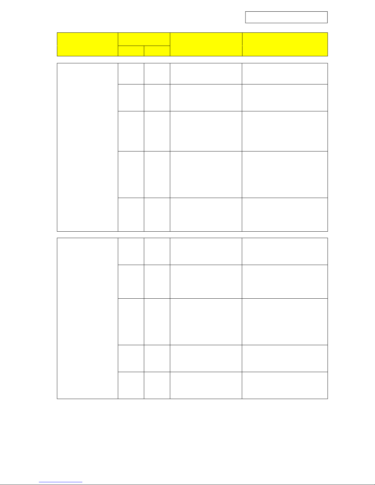
Models 3.2 - 13.2, µchiller control
Blue Box - Page 68
SYMPTOM
OPERATION
PROBABLE CAUSE
POSSIBLE CORRECTIVE ACTION
COOLING
HEATING
A)
No compressor
⊗ ⊗
No mains power Check presence of mains power
running. Fans
stopped (display off)
⊗ ⊗
Main power switch Off
(position "O")
Turn mains power selector to
position "I"
⊗ ⊗
No power to control circuits Check condition of fuses FU50,
FU51, FU52.
Check operation of the
transformer
⊗ ⊗
Incorrect phase sequence
(relay KA5 with only green
LED illuminated)
Invert two of the phase wires of
the power feed line; when the
unit is powered up again both
the green LED and the yellow
LED should light
⊗ ⊗
Relay KA5 with green and
yellow LEDs off
Check fuses FU56;
If fuses are OK replace phase
sequence relay
B)
No compressor
running. Fans
⊗ ⊗
Unit in stand-by mode Start unit (see relative section of
the manual)
stopped (display on
no alarm messages)
⊗ ⊗
No consent from service
thermostat
System at set-point temperature,
no heating/cooling demand;
check settings and operation.
⊗ ⊗
No external consent Check operation of circulating
pumps, flow switches, bleed air
from the system; check that
contacts 1 and 2 are closed,
check other external consents.
⊗ ⊗
Compressor motor burnt
out or compressor seized
Replace compressor
⊗ ⊗
Anti-recycle timer running Wait for 5 minutes until the
timer generates a consent
Page 75
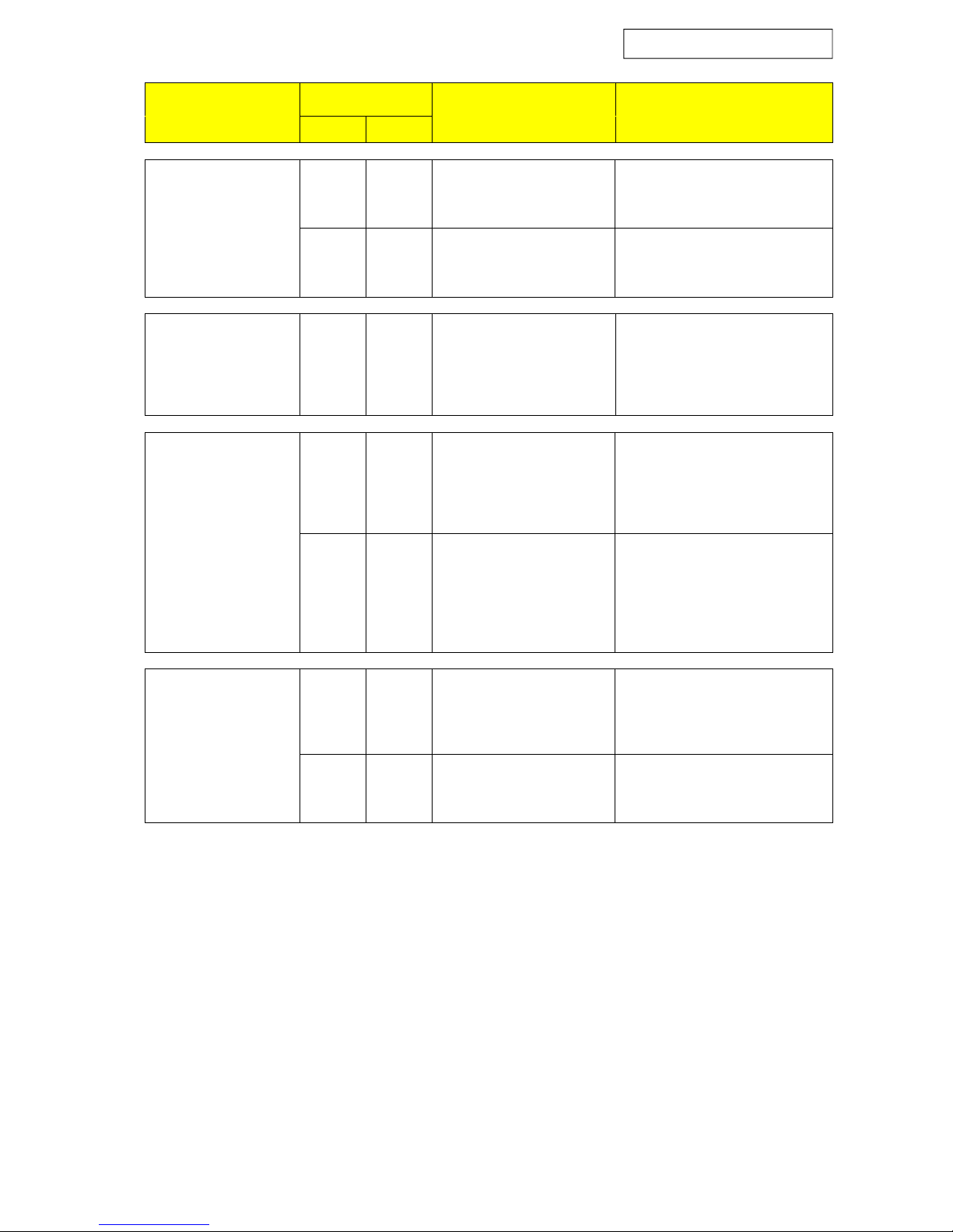
Models 3.2 - 13.2, µchiller control
Blue Box - Page 69
SYMPTOM
OPERATION
PROBABLE CAUSE
POSSIBLE CORRECTIVE ACTION
COOLING
HEATING
C)
No compressor
running. Fans stopped
⊗ ⊗
No water flow at
evaporator
Check hydraulic system
(display On with
alarm "FL")
⊗ ⊗
Faulty flow switch Check contact of flow switch
and replace if necessary
D)
No compressor
running. Fans stopped
(display On with alarm
“F1” or “F2”)
⊗ ⊗
Fan thermal protection
intervention
Check insulation between
windings and between windings
and earth; replace fan if
necessary.
E)
No compressor
running. Fans stopped
(display On with alarm
"A1")
⊗ ⊗
No consent of defrost
thermostat due to
insufficient water flow rate
Check hydraulic circuit and wait
until the water temperature
exceeds the value necessary for
the unit to restart
⊗ ⊗
No consent of defrost
thermostat due to
insufficient glycol
concentration
The programmed set-point is too
low for the percentage of glycol
in the circuit. Increase the glycol
percentage and reduce the
defrost set-point.
F)
No compressor
running. Fans stopped
(display On with
⊗ ⊗
Connections to evaporator
inlet temperature sensor
interrupted
Restore correct connection of
temperature sensor
alarm "E1")
⊗ ⊗
Evaporator inlet
temperature sensor faulty
Replace temperature sensor
Page 76
Models 3.2 - 13.2, µchiller control
Blue Box - Page 70
SYMPTOM
OPERATION
PROBABLE CAUSE
POSSIBLE CORRECTIVE ACTION
COOLING
HEATING
G)
No compressor
running. Fans running
⊗ ⊗
Resistance RK3 or RK4
faulty or disconnected
Check resistance and replace if
necessary
(display On with
alarm "E3" or "E5")
⊗ ⊗
Connections to pressure
sensor interrupted (HP
version only or if
condensation pressure
control with fan speed
regulator is fitted)
Restore correct connections to
pressure sensor ("E3" refers to
compressor 1, "E5" refers to
compressor 2)
⊗ ⊗
Faulty pressure sensor (only
on HP version or if
condensation pressure
control with fan speed
regulator is fitted)
Replace pressure sensor ("E3"
refers to compressor 1, "E5"
refers to compressor 2)
H)
Unit runs with
insufficient capacity
(Display On without
⊗ ⊗
Insufficient refrigerant
charge
Check refrigerant circuits with
leak detector, repair leak and
recharge circuit
alarms)
⊗ ⊗
Presence of moisture in
refrigerant circuit
Replace refrigerant filter and, if
necessary, dehydrate and
recharge circuit
⊗ ⊗
One compressor fails to
start, power circuit open
and compressor contactor
energised
Find and eliminate the cause of
the protection intervention;
change the fuses.
If the fuses blow immediately,
replace the compressor.
⊗ ⊗
A compressor fails to start,
fuses are OK and
compressor contactor is deenergised
Check voltage across compressor
contactor coil and continuity of
coil; if necessary, replace coil
⊗
4-way reversing valve
seized or coil faulty
Check power supply and coils of
valves and replace valves if
necessary
Page 77
Models 3.2 - 13.2, µchiller control
Blue Box - Page 71
SYMPTOM
OPERATION
PROBABLE CAUSE
POSSIBLE CORRECTIVE ACTION
COOLING
HEATING
I)
Compressor 1 and/or 2
not working (display
⊗ ⊗
Circuit overcharged Check refrigerant charge and
remove if necessary;
On with alarm
“H1” and/or “H2”)
⊗ ⊗
High pressure switch faulty Check and replace if necessary
⊗
Coil filters clogged; air flow
too low
Clean filters with compressed air
⊗ ⊗
Presence of incondensable
gas in the refrigerant circuit
Empty circuit, apply vacuum, and
recharge
⊗
Fans faulty Check and replace fans
⊗
Faulty circulating pump Check and replace
⊗
Defrost-end pressure switch
not working
Check and replace
⊗
Fan motor electrical
connections incorrect
Check that connections are as
indicated on electrical drawing
⊗
Fan contactors not
energised
Check voltage across coil of
contactor KM21 and electrical
continuity of coil circuit
Page 78
Models 3.2 - 13.2, µchiller control
Blue Box - Page 72
SYMPTOM
OPERATION
PROBABLE CAUSE
POSSIBLE CORRECTIVE ACTION
COOLING
HEATING
L)
Compressor 1 and/or 2
not working (display
On with alarm “L1”
and/or “L2”)
⊗ ⊗
Refrigerant circuit
completely empty
Check refrigerant circuit with
leak detector after pressurising to
approximately 4 bar. Repair leak,
apply vacuum, charge circuit.
⊗ ⊗
Low pressure switch faulty Check and replace if necessary
⊗
Coil filter clogged; air flow
too low
Clean filter with compressed air
⊗ ⊗
Refrigerant filter clogged Check and replace if necessary
⊗
Fans faulty Check and replace if necessary
⊗
Faulty water circulating
pump
Check and replace if necessary
⊗
Defrost pressure switch has
incorrect setting
Check and correct setting
⊗ ⊗
Liquid refrigerant valve not
completely open (if present)
Check and open fully
⊗ ⊗
Thermostatic expansion
valve not operating
correctly
Check, clean, or replace if
necessary
⊗
Fan motor electrical
connections incorrect
Check that connections are as
indicated on electrical schematic
⊗
Fan contactors not
energised
Check voltage across coil of
contactor KM21 and electrical
continuity of coil circuit
Page 79
Models 3.2 - 13.2, µchiller control
Blue Box - Page 73
SYMPTOM
OPERATION
PROBABLE CAUSE
POSSIBLE CORRECTIVE ACTION
COOLING
HEATING
M)
Compressor 1 and/or 2
not working (display
⊗ ⊗
Insufficient refrigerant
charge
Find leak with leak detector,
repair, and recharge circuit
On with alarm
“C1” and/or “C2”)
⊗
4-way valve locked Replace valve
⊗ ⊗
Lack of oil Check quantity of oil in circuit
and replenish as necessary.
Check that the circuit has all the
necessary measures to ensure oil
return to the compressor
N)
Ice on liquid refrigerant
pipe
⊗ ⊗
Liquid refrigerant filter
clogged
Replace filter
⊗ ⊗
Valve on liquid refrigerant
line (if present) not
completely open
Open valve fully
O)
Compressor 1 and/or 2
running. Ice on coil
(display On with
warning message “r1”)
⊗
Insufficient refrigerant
charge
Find leak with leak detector,
repair, and recharge circuit
P)
Compressors run
constantly
⊗ ⊗
Operating thermostat
incorrectly set or faulty
Check setting; replace
thermostat if necessary
⊗ ⊗
Lack of refrigerant gas
charge
Check and recharge if necessary
⊗ ⊗
Excess thermal load Reduce thermal load
Page 80
Models 3.2 - 13.2, µchiller control
Blue Box - Page 74
If the display presents alarms other than those described previously,
contact the Service organisation.
SYMPTOM
OPERATION
PROBABLE CAUSE
POSSIBLE CORRECTIVE ACTION
COOLING
HEATING
Q)
Anomalous noise from
system
⊗ ⊗
Compressor noisy Contact service organisation for
check and replacement if
necessary
⊗ ⊗
Thermostatic valve noisy Contact service organisation for
check and replenish refrigerant
charge
⊗ ⊗
Vibrating pipes Contact service organisation to
secure piping
⊗ ⊗
Casing panels vibrate Check that panels are properly
fastened; contact service
organisation if necessary
⊗ ⊗
Worn fan bearings Check; replace fan if necessary
Page 81
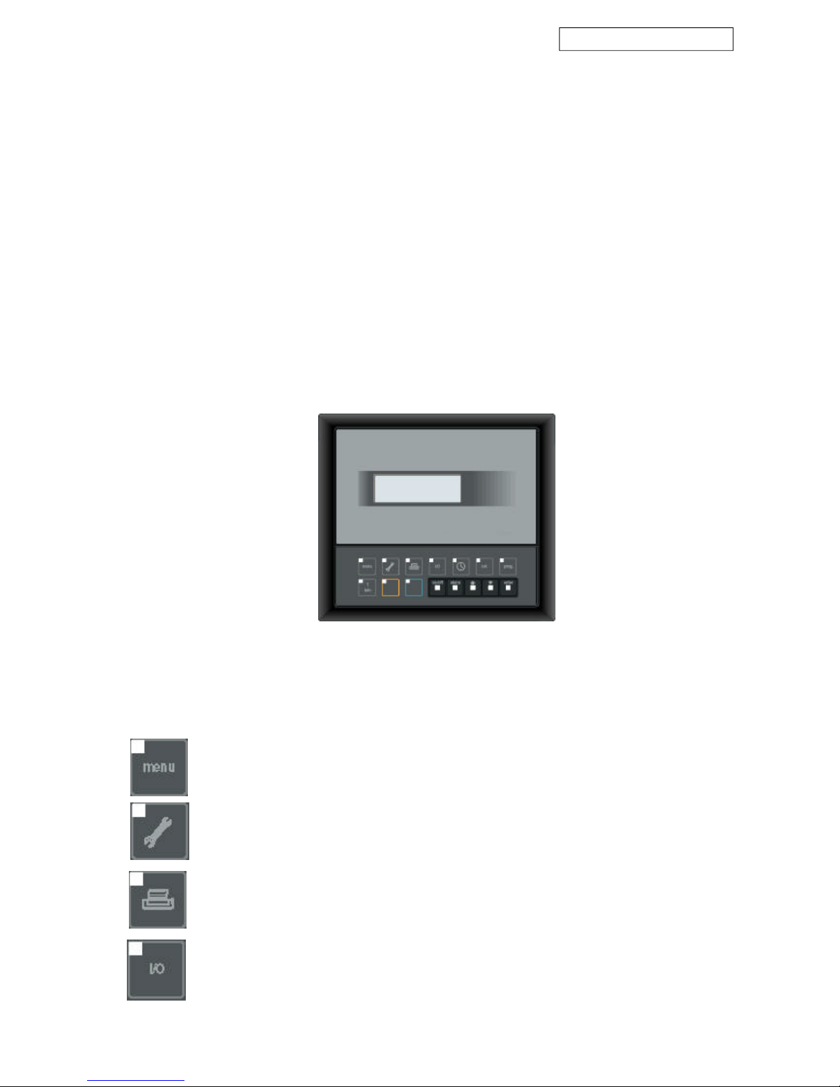
Models 14.4 - 26.4, pCO2 control
Blue Box - Page 75
8 UNIT WITH pCO2 MICROPROCESSOR (models from 14.4 to 26.4)
8.1 INTRODUCTION
The pCO2 electronic microprocessor controller with the DBBB0*P20Z program is designed to manage chiller and
heat pump units, with control of 4 compressors.
The program configuration manages the total control of the air-cooled unit with plate exchangers including
compressor start/stop times, safety devices and other auxiliary functions such as condensation control in cooling
mode, free-cooling, heat recovery and other functions described later in this manual.
The necessary hardware is optimised to obtain the maximum advantage from the available inputs and outputs;
the connection between various circuit boards and the user interface terminal is achieved via the pLANE using the
dedicated RS485 serial connector for network connections.
Each unit can also be connected to remote supervision and/or telediagnostics systems by means of an RS485
serial line.
Detailed information on the operation of the above systems is provided in the specific controller manual supplied
with the unit.
8.1.1 Display
The back-lit LCD display comprises 4 lines and 20 columns.
Figure 28
8.1.2 Keypad
In addition to the LCD display, the user interface is equipped with the following function keys:
“Menu” key: press this key from any menu to return to the opening menu.
Maintenance key: press this key to access the maintenance menus.
Print key: this key is currently not used.
"I/O" key: pressing this key opens the menus containing the status of the digital inputs and outputs
together with the values read on the analogue inputs and the value of the analogue outputs
Page 82
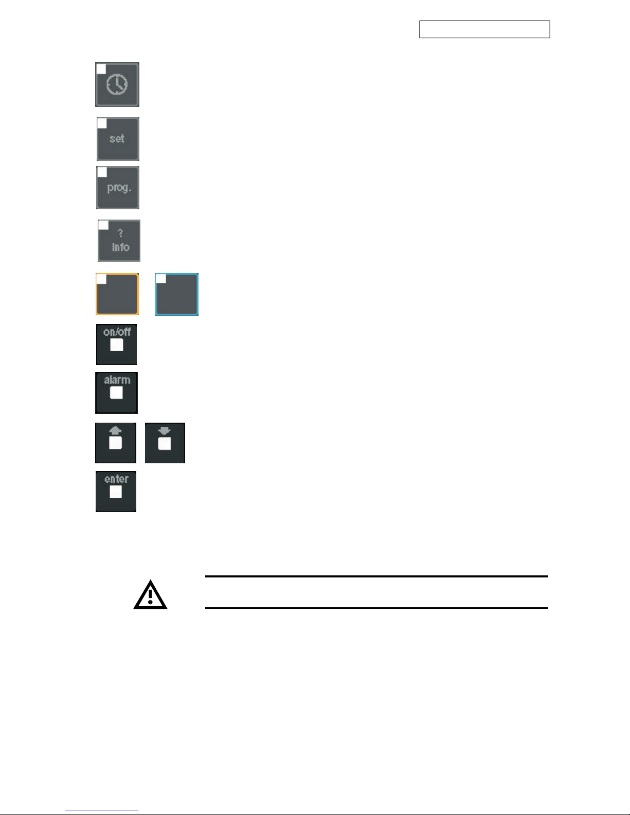
Models 14.4 - 26.4, pCO2 control
Blue Box - Page 76
Electronic components could be damaged by air temperature below -20
°C.
“Enter” key: pressing this key allows you to access fields containing editable parameters and also to
confirm any changes you make to such parameters.
"? info" key: pressing this key opens a menu in which the address of the component connected to
the terminal can be changed.
"Summer" key (blue) and "winter" key (red): in the case of chiller + heat-pump units,
press these keys to select the required operating mode.
“ON/OFF” key: press this key to switch from Stand- by to ON or vice versa.
“Alarm” key: this key serves to mute the alarm buzzer, display any active alarms, and reset them
in certain cases.
Arrow key: the arrow keys allow you to navigate through the menus; when an editable
field is selected, the arrow keys serve to change the current value.
“Clock” key: press this key to open the clock menus.
“Set” key: this key opens the menus in which the various operating set-points can be edited.
“Prog” key: this key opens the service menus.
Page 83

Models 14.4 - 26.4, pCO2 control
Blue Box - Page 77
8.2 OPERATING DESCRIPTION
8.2.1 Introduction
The microprocessor control regulates the water temperature of the evaporator maintaining it at the set-point
value acting on the compressors management.
As well as the compressors the controller manages the operation of other components of the chiller such as the
pumps (ST version) and fans, with relative operating times and alarms, and "ancillary" functions such as condensation
control, etc., as described below.
Almost all the parameters referred to below (set-points, differentials, calibration, delays...) can be programmed
by means of the various menus. Refer to the specific manual for the pCO2 controller.
8.2.2 Unit in stand-by mode
The unit is in stand-by mode when it is correctly supplied with power but not actually enabled to operate.
In this condition the display shows the values of the various machine parameters, but the operation of the
compressor is not inhibited.
Power-on is obtained by pressing the “ON-OFF” button of the microprocessor control or via an external interlock.
8.2.3 Enabling the unit
Start-up of the unit from stand-by mode can be achieved after closing the external enabling contact, by pressing
the “ON/OFF” button, or by means of a signal on the serial line.
Activation of the controller outputs that manage the various sections of the chiller is executed in strict compliance
with the operating times. If the “ON” button is pressed before the external interlocks are closed, the display
indicates which of the external interlocks is not yet enabled.
Operation of the pump has priority to the compressors, which can start only after the evaporator and condenser
pumps are running.
8.2.4 Pump management (ST units only)
If system pump control is included switching on the unit will automatically enable the pump.
If there are two pumps (run and stand-by) they will be activated alternately when the programmed operating time
limit for each pump has elapsed.
When the pumps are switched over both pumps will run in tandem, for a few seconds, to ensure a constant flow
of water in the system circuit.
When the unit is switched from active status to stand-by, if performed by opening an external permissive, the
currently active pump of the ST unit will be stopped with a delay interval, after the disconnection of the last
compressor in operation, making it possible to exploit the thermal inertia of the system.
8.2.5 Compressor start-up
The controller allows the compressors to be started if the flow switch input is closed within the compressor startup delay time interval. If the flow switch input opens, after the compressor has started, the trip is retarded if it
occurs within the time programmed for the compressor stop.
If the unit trips due to the opening of the flow switch input, the relative alarm is displayed.
Starting and stopping of the compressors and capacity step control is managed by the controller in accordance
with the building cooling demands.
8.2.6 Chiller mode operation
In chiller operation, the controller lowers the water temperature value, maintaining it as close as possible to the
programmed set-point.
Page 84

Models 14.4 - 26.4, pCO2 control
Blue Box - Page 78
In the standard version, in which the control acts on the evaporator entering water, the management of compressor
operation and capacity steps is linked to the difference between the entering water temperature and the programmed
set-point.
8.2.7 Heat pump mode operation
In heat pump operation, the controller increases the water temperature value, maintaining it as close as possible
to the programmed set-point.
Management of compressor operation is performed in the same way as already illustrated for chiller mode
operation.
8.2.8 Evaporator low temperature chilled water protection
If the evaporator leaving water temperature is lower than the limit value programmed in the low temperature
chilled water protection set-point, the controller will stop all the compressors and activate the low temperature
water alarm.
This alarm must be reset manually and the compressor restarted only when the evaporator leaving water temperature is equal to or higher than the alarm trip value, increased by the low temperature water differential.
The low temperature water alarm can only appear when the unit is switched on (in stand-by conditions the freeze
alarm is not operational).
8.2.9 Evaporator anti-freeze protection electric heater (optional)
In conditions that lead to tripping the freeze alarm, the controller energises the heater.
The heater remains powered for the entire time that the conditions for the freeze alarm continue.
Unlike the low water temperature alarm, which is enabled only when the unit is powered on, the anti-freeze
heater can be energised when the machine is on stand-by.
8.2.10 Compressor operation
When the unit is running correctly and no general alarms are present, the microprocessor controller starts the
compressors in accordance with the water temperature reading.
Compressor starts are staggered in accordance with preset delay intervals, thus avoiding excess input current
surges.
Before starting a compressor, the microprocessor checks the value of the delivery pressure by means of the
relevant transducer, the status of the high pressure switch and the compressor motor windings temperature by
checking the thermal protection.
When the compressor has been started, tripping of any of the safety devices will cause the compressor to stop
immediately and an alarm will be displayed.
While the compressor is running, discharge pressure and suction pressure are monitored constantly by means of
the relevant sensors.
On unit start-up the first compressor is started with a delay, set on the microprocessor controller, after the start of
the hydraulic system circulating pump.
Once started, each compressor must run for a minimum operating period, unless a critical alarm should trip in the
meantime.
The critical alarms which can stop the compressor during the minimum operating time are the high pressure
alarm and the compressor thermal cut-out alarm. Once stopped each compressor can be restarted only after a
minimum idle time or after a minimum time interval between two consecutive starts has elapsed.
The consecutive starting of two compressors or the consecutive starting of one compressor, is executed with
minimum delay intervals equal to the capacity step activation time.
Stopping compressors is also performed with a minimum programmed delay interval.
Page 85

Models 14.4 - 26.4, pCO2 control
Blue Box - Page 79
8.2.11 Compressor management
Start-up of the compressors is automatic when the reference water temperature changes with respect to the
programmed set-point.
Normally the reference water temperature is the value detected at the inlet to the chiller unit.
Balancing of duty hours over all the compressors in the unit is performed by selecting the rotation of starts.
With the rotation function of starts active, the first compressor to start is the first one that previously stopped. The
first compressor to start will be the one with the least operating hours.
8.2.12 High and low pressure alarms
Discharge pressure (high pressure) and suction pressure (low pressure) are managed by the microprocessor controller
through the relevant sensors.
When a compressor is running, the controller checks that:
- Discharge pressure is always lower than the safety value set for cooling or heating mode operation. If the values
are exceeded, the controller immediately stops the compressor and displays a high pressure alarm. The high
pressure alarm can be reset manually on the controller only when the pressure detected by the discharge
pressure sensor is lower than the value that caused the alarm to trip, less the differential value.
- The suction pressure is always higher than the safety value set for operation in cooling or heating mode. If the
value read by the suction pressure sensor is lower than the limits set for the relative operating conditions, the
controller will stop the compressor and generate a low pressure alarm. The low pressure alarm is not instantaneous,
but operates after a preset delay interval, both in the starting phase and during the normal running of the
machine. The low pressure alarm can be reset automatically or manually, depending on the relative parameter
setting. In all cases the low pressure alarm can only be reset when the pressure detected by the suction sensor
is higher than the value that caused the alarm to trip, plus the differential value. It is possible to program the
number of permissible consecutive compressor starts before the unit shuts down in safety status.
8.2.13 Low ambient temperature kit (option - condensing control with fan speed regulator)
As the ambient air temperature decreases the necessary condensing pressure for correct operation of the chiller
cycle is maintained, within the machine operating range, by adjusting the cooling air flow through the condenser.
Condensing pressure control is only active when the machine is operating in chiller mode.
When the unit is operating in heat pump mode this function is inhibited and the fans are forced to their maximum
speed.
The controller checks the condensing pressure and adjusts fan speed on the basis of the circuit with the highest
pressure reading. The speed regulator adjusts fan speed with a phase control system that minimises problems
related to electromagnetic compatibility.
Speed control is available over a 40-100% range. At the time of start-up the fans always run at 40% nominal
speed.
8.2.14 Changeover from chiller to heat pump and vice versa
The changeover from chiller to heat pump and back can be performed at any time, either by means of an
external signal on a digital input, from the keypad, or via the serial line. The operating mode changeover must be
only seasonal and only with the unit off.
After a mode changeover, the controller re-starts the unit in the new mode with a factory set minimum delay
time.
The unit operates with temperature control on the inlet to which has been inactive for the longest time. the unit
(or return from the system).
8.2.15 Defrosting (heat pump units only)
Page 86

Models 14.4 - 26.4, pCO2 control
Blue Box - Page 80
During winter heat pump mode operation the finned coil of the air cooled condenser functions as an evaporator,
cooling and dehumidifying ambient air.
During heat pump operation, the evaporation pressure is monitored to prevent it from falling below a preset
value. The evaporation control is active only during heating mode operation.
Depending on the ambient air temperature and humidity conditions, condensate or frost will tend to form,
consequently obstructing the free passage of air and causing thermal insulation. The frost that builds up on the
coil obstructs the passage of air and reduces the available heat exchange surface area (and thus the thermal
efficiency) and can damage the heat exchanger.
Defrosting is the procedure that eliminates the ice that has formed on the evaporator coil during heat pump mode
operation of an air/water unit.
Defrosting is performed simultaneously for the entire unit.
All heat pump versions are equipped with a control that activates an automatic coil defrost cycle when necessary.
After starting however, the first defrost cycle will be started after a preset minimum operating time to allow the
formation of sufficient thermal inertia to allow the cycle to be completed successfully.
Defrost cycle activation is based on the detection of a low suction pressure value due to insufficient heat exchange
between the evaporator and the air due to the formation of a layer of ice, which exerts a thermal insulation
effect. For a defrost cycle to be able to start a suction pressure of at least one of the currently operating compressors
must remain below the pressure set for the defrost cycle trip signal for a preset time interval.
Before starting to defrost the coils, all the compressors are started, after which the unit reverses its operation from
heat pump to chiller mode.
When the cycle is reversed the fans stop and the compressors force hot gas into the coil.
A pressure switch on the high pressure circuit maintains the discharge gas pressure below the defrost end value.
To maintain the pressure lower than the defrost end pressure the pressure switch activates the fans.
To reduce the air flow and obtain more efficient heating of the outer part of the coil, the pressure switch signal
causes the fans to rotate in reverse.
When the defrost end temperature is reached, as measured by a thermostat with a probe located in the lower
part of the coil, the pressure switch allows the discharge pressure to reach the defrost end pressure.
When the defrost end pressure has been reached, the controller reverses the unit from chiller mode to heat pump
mode, thereby terminating the defrost procedure.
Even though in certain conditions the surface temperature of the coil and the condensation pressure fail to reach
the defrost values within the preset time limit, the defrost cycle is forcibly terminated as though the defrost end
signal were present. The controller restarts the fans, and when the pressure lowers again to the preset value, it
reverses the unit’s operating mode again.
If the defrost cycle is forcibly interrupted, with the timeout signal, a message is displayed on the controller,
although no controller functions are activated.
The defrost timeout alarm is automatically cleared from the active alarms menus when a defrost cycle terminates
normally because the defrost end pressure has been reached. In any event, the alarms historical file will contain
a record of all defrost cycles that were terminated forcibly due to a timeout intervention.
Consecutive defrost cycles must be at least 30 minutes apart. If the forced defrost signal persists, inform the
Service organisation.
8.2.16 Total heat recovery (option)
Heat recovery is the function where all the energy that would normally be rejected to the air cooled condenser is
recovered at a refrigerant to water condenser installed in series with the air-cooled condenser.
The heat recovery process is managed by the microprocessor controller.
During energy recovery the fans are stopped and the condensing coil is by-passed via solenoid valves connected
downstream of the thermostat valve. The machine is equipped with a liquid receiver.
Heat recovery can only occur when the water temperature at the recovery exchanger inlet is lower than the
recovery set-point. Heat recovery is terminated when the temperature increases by the recovery differential
value.
It is mandatory to use a condensing pressure control valve (one for each hydraulic circuit) or three-way valve,
fitted by the installer, to avoid condensation values that are incompatible with operation of the machine.
8.2.17 Dual set-point (option)
Page 87

Models 14.4 - 26.4, pCO2 control
Blue Box - Page 81
Operation with a dual set-point is possible only in chiller mode.
With double thermostatic valves and solenoid valves that are automatically switched according to the required
expansion temperature. Two set-point values can be programmed on the microprocessor controller via the keypad
or a digital input. Switching of the thermostatic valves is always automatic, in accordance with the water temperature.
The valves are sized on the basis of the temperature values specified at the time of the order. The machine
operating limits shown in the catalogue are not affected. If the hydraulic circuit contains glycol in sufficient
quantities to eliminate the risk of freezing, the lower limit is extended to a minimum of -5 °C leaving water
temperature.
8.2.18 Operation leaving water temperature control (option)
With leaving chilled water temperature control the reference sensor must be installed on the evaporator outlet or,
if there is more than one evaporator, on the common outlet pipeline downstream from the relative manifold.
The unit’s capacity steps are activated / deactivated with delay intervals in relation to a dead zone. When the
leaving water temperature is higher than the programmed set-point compressors start is enabled.
Page 88
Models 14.4 - 26.4, pCO2 control
Blue Box - Page 82
Important: on heat pump versions the operating cycle must be reversed
at the start and end of the season. Frequent switching from summer to
winter mode, and vice versa, should be avoided at all costs because it
can lead to malfunctions and subsequent breakdown of the compressors.
Figure 29
If the unit fails to start: do not change internal electrical connections on
penalty of immediate invalidation of the warranty.
8.3 STARTING THE UNIT
For the start-up procedure refer also to the microprocessor controller manual.
- Close the external enabling contacts
- Press the "ON" button on the microprocessor controller
- If all the controls are enabled the display will show the message "UNIT ON"
After having performed the above procedures the unit will start automatically after a delay of approximately 5
minutes, assuming that the enabling signals of the microprocessor, the flow switches, and the water pumps
continue to be present.
During idle periods do not disconnect the unit from the power supply (the
compressor crankcase heaters must remain switched on in these intervals).
Disconnect the unit from the power supply only in the event of prolonged
disuse (e.g. seasonal shutdowns). For temporary shutdown of the unit
refer to the guide lines given in paragraph 8.4.
8.4 STOPPING THE UNIT
8.4.1 Temporary stop:
- To stop the unit press the "OFF" button on the front panel.
8.4.2 Seasonal stop:
- Disconnect the power supply
- Drain the system circuit (unless it contains a water/glycol solution)
- When the unit is to be restarted repeat the initial start-up procedure
Warning: do not use the machine main power switch to stop the unit:
this switch must be used to disconnect the electrical supply when no
current is flowing on the circuit, i.e. only when the unit is in OFF status.
Note also that if power is disconnected from the unit, the crankcase
heaters will be switched off with the resulting risk of compressor damage
at the time of restarting.
Page 89
Models 14.4 - 26.4, pCO2 control
Blue Box - Page 83
8.5 EMERGENCY STOP
Emergency stops are obtained by turning the red colour main disconnect switch on the electrical panel to position 0.
9. TROUBLESHOOTING
The following pages contain a list of the most common causes that can result in the shutdown or anomalous
operation of the chiller. Faults are arranged in accordance with easily identifiable symptoms.
In relation to possible corrective action, adopt the maximum attention in
the operations you intend to perform as overconfidence coupled with
insufficient attention due to lack of expertise can lead to serious accidents.
We therefore recommend that Blue Box or other skilled HVAC engineers
are contacted to identify and correct the problem.
Page 90
Models 14.4 - 26.4, pCO2 control
Blue Box - Page 84
SYMPTOM
OPERATION
PROBABLE CAUSE
POSSIBLE CORRECTIVE ACTION
COOLING
HEATING
A)
No compressor
running. Fans
⊗ ⊗
No mains power Check presence of mains power
stopped (display Off)
⊗ ⊗
Main power switch Off
(position "O")
Turn main power selector to
position "I"
⊗ ⊗
No power to control circuits Check fuses FU50, FU51, FU52.
Check operation of transformer
⊗ ⊗
Incorrect phase sequence
(relay KA5 with only green
LED lit)
Invert two of the phase wires of
the power supply line; when the
unit is powered up again both
the green and yellow LEDs
should light
⊗ ⊗
Relay KA5 with green and
yellow LEDs off
Check fuses FU56;
If fuses are OK replace phase
sequence relay
B)
No compressor
running. Display On:
”OFF from external
consent”
⊗ ⊗
No external consent Check presence of external
consent; if not present, bridge
terminals 1 and 2
C)
No compressor
running. Display On:
”OFF from supervision
system”
⊗ ⊗
No consent from
supervision system
Activate operation from
supervision system
D)
No compressor
running. Display On:
”OFF”
⊗ ⊗
No consent from “on/off”
key of user interface
Press “on/off” key
Page 91
Models 14.4 - 26.4, pCO2 control
Blue Box - Page 85
SYMPTOM
OPERATION
PROBABLE CAUSE
POSSIBLE CORRECTIVE ACTION
COOLING
HEATING
E)
No compressor
running. Display On:
unit ON with alarm
⊗ ⊗
220V fuses burnt-out
(FU51)
Change fuses. If fuses burn-out
again, contact assistance
“High Pressure
Compressor 1, 2, 3, 4”
⊗
Fans contactor not
energised
Check voltage across the
contactor coil and coil continuity
⊗
Fan fuses burnt-out (FU21) Check cause of burn-out and
change fuses.
⊗
Fan motor faulty Check and replace if necessary
F)
No compressor
running. Display On:
unit ON with alarm
“Fans protection”
⊗ ⊗
Fan thermal protection
intervention
Check insulation between
windings and from windings to
ground
⊗ ⊗
Fan motor faulty Check and replace if necessary
⊗ ⊗
Faulty fan alarm relay Check and replace relay
G)
No compressor
running. Display On:
unit ON with alarm
⊗ ⊗
Drop in power feeding
voltage
Check voltage stability and fit
appropriate protection if
necessary
“Thermal protections
Compressor 1, 2, 3, 4”
⊗
⊗
Setting of thermal
protections
Contact assistance
⊗ ⊗
Circuits partially discharged Call service to replenish charge
Page 92
Models 14.4 - 26.4, pCO2 control
Blue Box - Page 86
SYMPTOM
OPERATION
PROBABLE CAUSE
POSSIBLE CORRECTIVE ACTION
COOLING
HEATING
H)
No compressor
running. Display On:
unit ON with alarm
⊗
Insufficient percentage of
glycol in hydraulic circuit
Restore correct glycol percentage
“Low Pressure
compressor 1, 2, 3, 4”
⊗
⊗
Both circuits have
insufficient refrigerant
charge
Find possible leaks in circuit,
repair, and recharge
⊗
Fans contactor not
energised
Check voltage across the
contactor coil and coil continuity
⊗
Fan motor faulty Check and replace if necessary
⊗
Insufficient water flow to
evaporator
Check hydraulic circuit
⊗
Incorrect setting of defrost
set-point
Check and correct setting if
necessary
I)
No compressor
running. Display On:
unit ON with alarm
“Exceeded Threshold
⊗
Insufficient water flow to
evaporator
Increase water flow to
evaporator and check
temperature rise
Low Temperature of
leaving User Water”
⊗
⊗
Faulty controller
Contact service organisation
⊗
Defrost sensor short circuit Contact service organisation
J)
No compressor
running. Display On:
unit ON with alarm
“Exceeded Threshold
Low Temperature User
Water Reference”
⊗
Excessive thermal load Reduce thermal load
Page 93
Models 14.4 - 26.4, pCO2 control
Blue Box - Page 87
SYMPTOM
OPERATION
PROBABLE CAUSE
POSSIBLE CORRECTIVE ACTION
COOLING
HEATING
K)
No compressor
running. Display On:
unit ON with alarm
“Exceeded Threshold
High Temperature of
⊗
Excessive thermal load Wait until entering water
temperature is below the alarm
set point. Start hydraulic circuit
of evaporator and unit. If not
sufficient contact assistance.
entering User Water
⊗
Refrigerant circuits partially
discharged
Call assistance
L)
No compressor
running. Display On:
unit ON with alarm
⊗ ⊗
Power supply voltage not
stable
Check power supply voltage; if
not correct contact the electricity
company
“No power to
Control circuits”
⊗ ⊗
Fuses FU51 burnt-out Check cause of fuse burn-out
and replace fuses.
M)
No compressor
running.
⊗ ⊗
No water flow to
evaporator
Check hydraulic circuit
Display On: unit
OFF with alarm
“Flow Switch Alarm”
⊗ ⊗
Flow switch faulty Check flow switch contact and
replace if necessary
N)
No compressor
running. Display On:
unit OFF with alarm
”Incorrect Phase
Sequence” and phase
sequence relay with
green LED On and
orange LED Off
⊗ ⊗
Incorrect phase sequence Invert two of the phase wires of
the power supply line
O)
No compressor
running. Display On:
unit OFF with alarm
”Incorrect Phase
Sequence” and phase
sequence relay with
green and orange LEDs
On
⊗ ⊗
Faulty relay Check to ensure that relay closes
contact
Page 94
Models 3.2 - 13.2, µchiller control
Blue Box - Page 88
SYMPTOM
OPERATION
PROBABLE CAUSE
POSSIBLE CORRECTIVE ACTION
COOLING
HEATING
P)
No compressor
running. Display On:
unit OFF with alarm
⊗ ⊗
Fuses FU56 burnt-out Check fuse FU56 and replace if
necessary
”Incorrect Phase
Sequence”
and phase sequence
relay with green and
orange LEDs Off
⊗ ⊗
One of the three phases is
not present
Check connection of each phase
Q)
No compressor
running. Display On:
unit ON without alarm
⊗ ⊗
No consent from digital
input to compressors
Check consent to compressors
and close relative contacts
⊗ ⊗
Unit at temperature Normal operation
⊗ ⊗
Compressor fuses burntout
Check continuity of fuses; if
burnt-out call service
⊗ ⊗
Controller faulty Call service
R)
One or more
compressors switched
off. Display On with
⊗ ⊗
Excess refrigerant charge Check refrigerant charge and call
service organisation
alarm “High Pressure
Compressor”
⊗ ⊗
Refrigerant circuit contains
non-condensable gas
Empty circuit, apply vacuum, and
recharge
⊗ ⊗
High pressure switch
incorrectly set or faulty
Check pressure switch setting
⊗
Condenser coil or coil filters
(if present) clogged
Clean coil and filters (if present)
with compressed air
Page 95
Models 14.4 - 26.4, pCO2 control
Blue Box - Page 89
SYMPTOM
OPERATION
PROBABLE CAUSE
POSSIBLE CORRECTIVE ACTION
COOLING
HEATING
S)
One or more
compressors switched
⊗ ⊗
Insufficient refrigerant
charge due to leak in circuit
Call service organisation
off. Display On with
alarm “Low Pressure
Compressors”
⊗ ⊗
Thermostatic valve faulty Call service organisation
⊗ ⊗
Solenoid valve of liquid
refrigerant line faulty (if
present)
Call service organisation
⊗
Dehydrating filter clogged Call service organisation
⊗
Evaporator coil or coil filters
(if present) clogged
Clean coil and filters (if present)
with compressed air
T)
One or more
compressors switched
off. Display On with
alarm “Compressor
Thermal Protections”
⊗ ⊗
Problems at the compressor Call service organisation
U)
One or more
⊗ ⊗
Unit capacity step active Normal operation
compressors Off.
Display On
without alarms
⊗ ⊗
Fuses burnt-out Call service organisation
⊗ ⊗
Faulty controller Call service organisation
⊗ ⊗
No external consent to
compressor
Check compressor external
consent
V)
All compressors
running. Display On
with alarm
“Compressor
Maintenance”
⊗ ⊗
Compressors specified by
alarm require maintenance
Call service for scheduled
maintenance
Page 96
Models 14.4 - 26.4, pCO2 control
Blue Box - Page 90
If the display presents alarms other than those described above, contact
the service organisation.
SYMPTOM
OPERATION
PROBABLE CAUSE
POSSIBLE CORRECTIVE ACTION
COOLING
HEATING
W)
All compressors
running. Display On
with alarm “Unit
Maintenance”
⊗ ⊗
Unit maintenance required Call service for scheduled
maintenance
X)
All compressors
⊗ ⊗
Excessive thermal load Call service organisation
running without
stopping. Display
On without alarm
⊗ ⊗
Refrigerant circuits partially
discharged
Call service organisation
⊗
Liquid refrigerant filter
clogged
Clean or replace
⊗ ⊗
Controller not working Call service organisation
⊗
4-way reversing valve not
energised
Check power supply and
solenoid valve coils and replace if
necessary
Y)
Anomalous noise from
system
⊗ ⊗
Compressor noisy Contact service organisation for
check and replacement if
necessary
⊗ ⊗
Thermostatic valve noisy Contact service to check and add
refrigerant
⊗ ⊗
Vibrating pipes Contact service organisation to
secure pipes
⊗ ⊗
Casing panels vibrate Check that panels are properly
fastened; contact service
organisation if necessary
⊗ ⊗
Worn fan bearings Check; replace fan if necessary
Page 97

Blue Box - 91
10 CHECKS DURING OPERATION
10.1 INTRODUCTION
- Check that the water temperature at the evaporator inlet is close to the set-point value of the service thermostat.
- For units equipped with pump units, if the pump runs noisily, close the relative delivery cock until the pump starts
running smoothly again. This situation can occur when system pressure drops deviate significantly from the
pump available pressure.
10.1.1 Checking the refrigerant charge
- After a few hours of unit operation check that the sight glass moisture indicator has a green coloured core. if the
core is yellow, moisture is present in the circuit. In such a situation the circuit must be dehydrated by a qualified
technician.
- Check the sight glass for air bubbles. A constant passage of bubbles through the sight glass could indicate that
the refrigerant must be replenished. Occasional bubbles are considered normal.
- Check that refrigerant liquid superheating is between 5 and 7 °C; to do this:
1) measure the temperature using a contact thermometer placed on the compressor suction pipeline;
2) read the temperature, equivalent to the pressure read on the pressure gauge connected to the compressor
suction side (saturation temperature corresponding to suction pressure); for units charged with R407C
refrigerant, refer to the D.P. (Dew Point) pressure gauge scale.
The difference between the temperatures measured in this manner is equivalent to the superheating value.
- Check that refrigerant subcooling is between 5 and 7 °C; to do this:
1) measure the temperature using a contact thermometer placed on the compressor discharge pipeline;
2) read the temperature, equivalent to the pressure read on the pressure gauge connected to the liquid
connection at the condenser outlet (saturation temperature corresponding to condenser delivery pressure);
for units charged with R407C refrigerant, refer to the B.P. (Bubble Point) pressure gauge scale.
The difference between the temperature values measured in this manner is equivalent to the subcooling
value.
Page 98
Blue Box - 92
TABLE 3 - CALIBRATION OF CONTROL EQUIPMENT
TABLE 4 - CALIBRATION OF SAFETY DEVICES
* Chiller / heat pump
CAPACITY STEPS
CONTROL ELEMENT SET POINT DIFFERENTIAL SET POINT DIFFERENTIAL
Service calibration (summer) °C 10 2 9 3
Service calibration (winter) °C 42 2 43 3
2 4
ACTIVATION DIFFERENTIAL RESET
SET-POINT
No-frost setting °C 3 6 manual
Maximum pressure switch setting bar 27 7 manual
Minimum pressure switch setting bar 2.5 / 0.7 * 1 manual (from controller)
Evaporator heater setting °C 3 6 automatic
Defrost start setting bar 2 -- automatic
Defrost end setting bar 18 -- automatic
Defrost end thermostat setting °C 5 -- automatic
Defrost pressure switch setting bar 16 2 automatic
CONTROL ELEMENT
11. CALIBRATION OF CONTROL EQUIPMENT
11.1 INTRODUCTION
All the control equipment is factory calibrated before the machine is shipped. Control equipment and safety
devices should nonetheless be checked after a reasonable period of operation. Calibration values are given in
Tables 3 and 4.
All service operations on the control equipment must be carried out by
QUALIFIED PERSONNEL ONLY; incorrect calibration values can cause
serious damage to the unit and personal injury.
Page 99
Blue Box - 93
12. MAINTENANCE AND PERIODIC CHECKS
12. 1 WARNINGS
Adopt the maximum caution when working in the vicinity of the finned
coils because of the sharp edges of the aluminium fins.
After performing maintenance work always refit the outer panels and
secure them with the screws.
All operations described in this chapter MUST BE PERFORMED
EXCLUSIVELY BY QUALIFIED PERSONNEL.
Make sure that the unit has been disconnected from the power supply
before carrying out any work or accessing internal parts.
The compressor head and discharge pipeline can reach high temperatures.
Always exert caution when working in the vicinity of the compressor.
12.2 INTRODUCTION
Carry out the following periodic checks to ensure the unit is operating correctly:
CHECK PERIOD
Check that safety and control devices work correctly as previously described monthly
Check that all the terminals within the electric panel and compressor are tight The
sliding terminals of the contactors should be periodically cleaned: if any damage is
found, replace the contactors
monthly
Check the sight glass to verify the refrigerant charge. monthly
Check that there is no oil leakage from the compressor monthly
Check that there is no water leakage in the hydraulic system monthly
If the unit is to be stopped for a long period the hydraulic circuit, including all pipes and
heat exchangers, should be drained. This is compulsory if the ambient temperature is
expected to fall below the freezing point of the liquid employed.
seasonal
operation
Check process water levels monthly
Check that the flow switch is operating correctly. monthly
Check that the crankcase heater is operating correctly and there is a power supply. monthly
Clean metallic filters on water piping monthly
Clean the finned coil or the filter coils, if present, by means of compressed air, which
should be directed in the opposite direction to the normal direction of air flow. If the
coil is completely clogged clean with a jet of water.
monthly
Execute a defrost test (heat pump units only) monthly
Check the condition, anchorage, and balancing of fans every 4 months
Check the colour of the sight glass core (green = no moisture, yellow = moisture
present): if it is yellow change the refrigerant filter
every 4 months
Check that the noise level has not increased. every 4 months
Page 100
Blue Box - 94
12.3 REPAIRING THE REFRIGERANT CIRCUIT
If repairs have been made to the refrigerant circuit, perform the following steps:
- leak test;
- vacuum and dehydration of refrigerant circuit;
- refrigerant charge.
If the circuit is to be emptied, use the appropriate equipment to collect
the refrigerant.
12.3.1 Leak test
Charge the refrigerant circuit to a pressure of 15 bar with dry nitrogen gas by means of a cylinder fitted with a
pressure reducer. Check the circuit for leaks with a leak detector. The formation of bubbles or foam indicates the
presence of leaks.
If leaks are found during the test, empty the refrigerant circuit and then repair the point of leakage by welding
with appropriate alloys.
Do not use oxygen instead of nitrogen: explosion hazard.
12.3.2 High vacuum and dehydration of the refrigerant circuit
To generate a high vacuum in the refrigerant circuit use a high vacuum pump able to reach 0.1 mbar of absolute
pressure with a flow rate of 10 m3/h. With this type of pump, a single vacuum cycle is normally sufficient to reach
an absolute pressure of 0.1 mbar.
If this type of pump is not available, or in the event that the circuit has been left open for a long period of time,
you are strongly advised to use the triple evacuation method. This procedure is also prescribed in the event of
moisture in the refrigerant circuit.
Connect the vacuum pump to the charge connector.
Proceed as follows:
- Evacuate the circuit to a pressure of at least 35 mbar absolute. Charge the circuit with nitrogen to a relative
pressure of approx. 1 bar.
- Repeat the operation described above.
- Repeat the operation described above for the third time in order to reach the highest degree of vacuum possible.
This procedure should guarantee the elimination of up to 99% of contaminants.
 Loading...