


Operator’ s And
Model:
Parts Manual
MANUAL NO. 8530 REV. 01 (07/29/03)
SC18

Forward:
Congratulations on the purchase of your new BlueBird equipment!
Your purchase demonstrates trust in the BlueBird name and exem-
plifies your desire to own durable equipment which is easy to operate and easy to maintain.
To get the full benefit of your purchase, you will need to understand
how to use the controls and many features of your machine. This
operator’s guide has been prepared to assist you in this process.
Please read this guide carefully and familiarize yourself with the basic safety procedures, operating tips, and maintenance information.
Close consideration of the recommendations contained in this
manual will save time, money , and provide years of productivity from
your unit.
As we hope to meet your future needs, please take the time to record
your model and serial number on the back cover of this manual.
This will greatly assist in identification of your model and for future
parts ordering.
2

CONTENTS
Index
Operator’s Guide Page
Specifications .............................................................................................. 3
Features and Controls................................................................................. 4
General Operating Instructions.................................................................... 5
Warnings .....................................................................................................5
Operating Instructions Page
Operator’s Tips ............................................................................................ 6
Operating on Hills ........................................................................................ 6
Before Y ou S t art........................................................................................... 6
Transporting ................................................................................................ 6
Sod Cutting.................................................................................................. 7
Maintenance and Service Instructions Page
Safety and Maintenance .............................................................................. 8
Safety .......................................................................................................... 8
Engine Service and Warranty...................................................................... 8
Lubrication Schedule................................................................................... 8
Inspection Schedule .................................................................................... 8
Blade Wear ................................................................................................. 9
Cleaning ...................................................................................................... 9
Adjusting Chain Tension .............................................................................. 9
Storage ........................................................................................................ 9
Parts - Main Frame...................................................................................... 10
Parts - Power Train ..................................................................................... 12
Parts - Blade Drive ...................................................................................... 14
Parts - Blade Depth Control ........................................................................ 16
Trouble Shooting Guide ............................................................................... 17
General Product Information
Warranty...................................................................................................... 21
SPECIFICATIONS
U.S. Metric
Engine - Honda: 5.5 hp 3.8 kw
Net Weight: 328 lbs 149 kg
Shipping Weight: 360 Ibs 164 kg
Width: 24 in 61 cm
Height: 36 in 91 cm
Length: 54 in 137 cm
Cutting Depth (max): 2.5 in 6.3 cm
Cutting Width: 18 in 46 cm
3
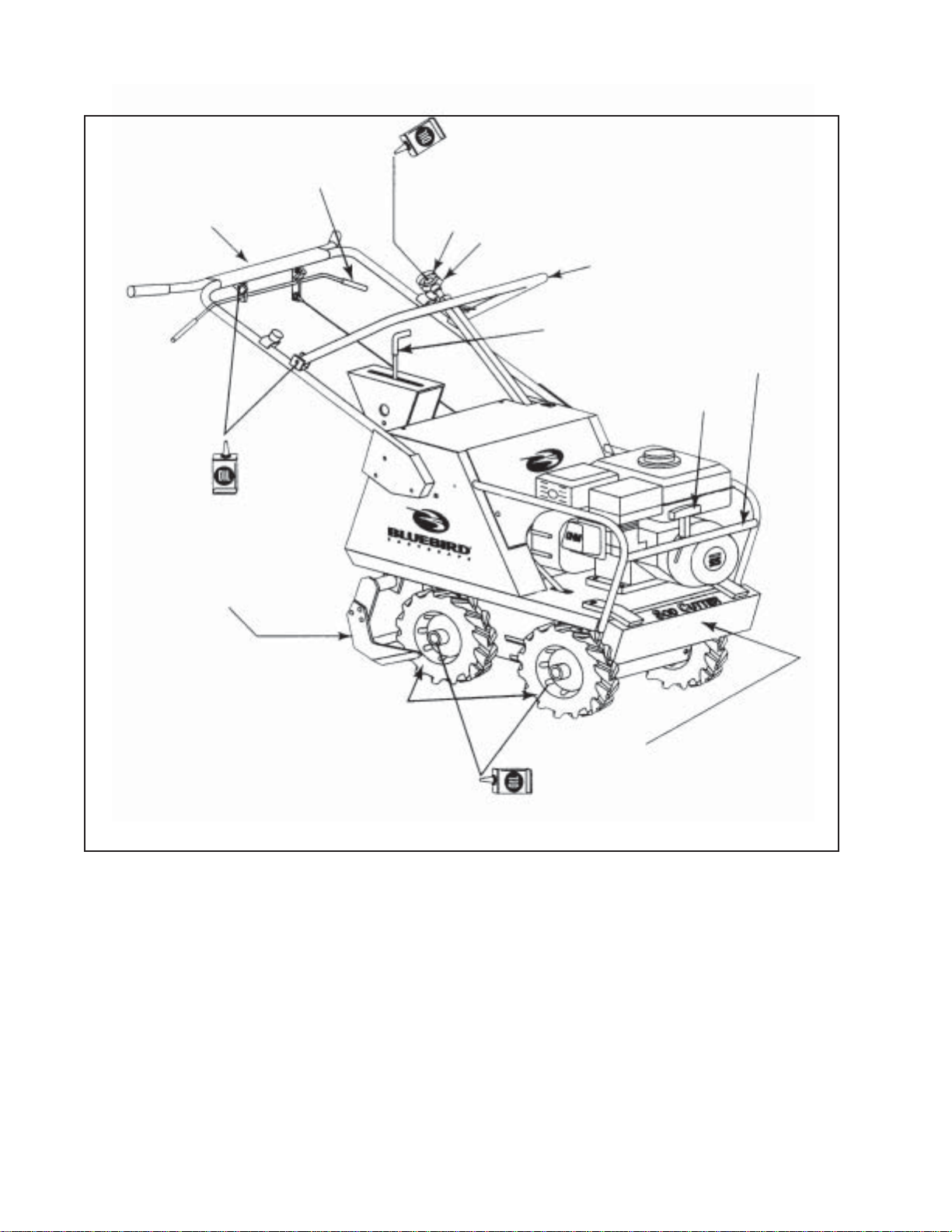
Antivibration Handle
FEATURES AND CONTROLS
Single
Clutch/Throttle
Depth
Adjustment
Knob
Depth Lock
Knob
Engagement
Shift Control Lever
Blade
Lever
Engine Guard
Engine Start
18-inch Blade
10-inch Tractor T read Tires
Powered by 4-Wheel Drive
Built-in Weight
Oil used in the engine (gray cap) 1. Refer to your engine manual for oil type, viscosity , weight
and capacity.
Oil used in the Clutch/Gear Box 1. Refer to your engine manual for oil type, viscosity , weight
and capacity. Reducer (yellow cap).
Transmission grease used 1. You should not need to service the transmission. Call
Tecumseh or your servicing dealer if needed.
2. Transmission is located directly behind the front axle
underneath the engine.
3. There is no dipstick for transmission.
4. Tecumseh Bentonite Grease part #788067B or equivalent.
4

OPERATING INSTRUCTIONS
GENERAL INFORMATION
This manual will assist you in the safe operation and proper maintenance of your BlueBird equipment. Read it thoroughly before attempting to operate the machine. Do not hesitate to call your
dealer or BlueBird if additional information is required.
The following safety symbols are used throughout the manual to alert you to information about
unsafe actions or situations:
DANGER: indicates immediate hazards that may result in severe injury or death.
WARNING: indicates unsafe actions or situations that may cause severe injury, death and or
major equipment or property damage.
CAUTION: indicates unsafe actions or situations that may cause injury and/or minor equipment or property damage.
This equipment should not be modified without the manufacturer’s prior written authorization. Doing
so without our written permission may not only affect the equipments performance and durability, but
also create safety hazards for the operator and the surroundings. Warranty will be void if changes
are made to the equipment without the manufacturer’s prior written authorization.
SAFETY PROCEDURES
DO:
• Only start with shift lever in neutral.
• Read all maintenance and service instructions before attempting work.
• Follow engine manufacturer operating and maintenance instructions.
• Inspect area to be cut and remove rocks, wire, string and other objects that might present a hazard
before starting.
• Identify and mark all in ground objects to be avoided, such as sprinkler heads, stakes, water
valves, clothes line anchors, etc.
• This machine was designed for sod cutting only. It is not intended for any other use.
DO NOT:
• Do not start in gear .
• Do not cut at high transport speeds.
• Do not use on any surface other than grass.
• Do not operate on slopes exceeding 35% grade.
• Do not place hands or feet near moving or rotating parts.
• Do not run engine in an unventilated area.
• Do not shift with throttle engaged.
• Do not run engine while servicing. Remove spark plug wire before servicing.
• Do not remove guards when operating.
• Do not lift this 330 lb. machine.
5

OPERATING INSTRUCTIONS
OPERATOR’S TIPS
• To engage reverse gear you may have to push the machine back and forth while pulling the shift
lever.
• Stop before shif ting gears.
• Cut going down hill on unlevel ground.
• End cuts by pushing the blade engagement lever forward while still holding the throttle to cut the
end of the sod strip as the blade rises.
• Soil conditions will effect cutting depth. Readjusting the blade depth may be required as you move
from hard soil to soft or moist soil conditions.
• Do not attempt sharp turns while cutting.
• Should I water before cutting?
It is usually not necessary to water before cutting. In extreme conditions, such as clay soil that is
very compacted, a simple test as follows will determine if you need to water before cutting. Use a
garden hand spade, weed tool, or even a large screwdriver to test the ground’s hardness. You
should be able to push the tool into the ground 2 to 3 inches with little effort.
If you are unable to do so, then watering may be advisable. Watering the day before should give
sufficient time for the soil to absorb the moisture. Use your hand tool to gauge the effectiveness of
your watering. Allow the grass to dry before cutting to provide adequate traction for sod cutting.
OPERATING ON HILLS
WARNING - DO NOT operate on hills exceeding 35% grade to prevent machine from rolling
over .
Please be aware that when operating on hills, you may experience:
• The need to exert greater effort to steer and maintain the balance of the machine.
• Uneven cutting depth, when operating across a hill. The shifted center of gravity may cause the
downhill side of the blade to penetrate to the maximum depth, while the uphill side may not.
With these factors in mind, you may find it more effective to:
• Operate the machine cutting down rather than across hills. You will achieve even cutting depth, and
enhance stability.
• A void hill side turns. Back up hills in reverse gear, then cut, going down.
BEFORE YOU START
• Read and understand this manual.
• Be sure engine oil is at engine manufacturer’s recommended level. (Refer to engine
manufacturer’s manual.)
• Put the sod cutter into neutral before starting.
• Place blade in transport position before starting.
TRANSPORTING
• Push the blade engagement lever forward to raise the blade.
• Select the desired gear (slow-fast-reverse).
• Pull the throttle while maintaining a firm grip on the handlebar .
• To make turns, push down on the handlebar to do “a wheelie,” then turn.
• Load into truck or trailer by driving up ramps in low gear . DO NOT LIFT! This 330lb machine is not
intended to be lifted by hand.
6

OPERATING INSTRUCTIONS
SOD CUTTING See Figure - Page 4
1. Position the sod cutter at your starting point with the blade out of the ground.
2. Pull the blade engagement lever toward you with one hand while lifting the handlebar with the
other hand.
3. Place the shift lever in slow gear (turtle icon).
4. Pull the throttle while maintaining a slight down pressure on the handlebar and cut a short
distance, then stop. Put shift lever in neutral.
5. Lift the edge of the sod to check the cut depth.
6. To change the depth, push the blade engagement lever forward, unlock the depth lock knob (red
knob), and turn the depth adjustment knob clockwise for less depth, or counterclockwise for
more depth; then lock the depth lock knob.
7. Repeat steps 2 through 6 as necessary to set depth of cut.
8. End cuts by pushing the blade engagement lever forward while holding the throttle to cut the end
of the sod strip as the blade exits the ground.
7

SAFTEY AND MAINTENANCE
CAUTION
Any modifications or additions to this equipment without written authorization from the manufacturer
will void all manufacturer’s warranties.
Do not operate this machine without first reading owners manual.
CAUTION
BlueBird parts have been designed and specified to meet commercial operating standards for
strength and durability . For reliability and preservation of design safety standards, replacement s
should only be made with genuine BlueBird parts or material of equivalent type and strength.
TWO MINUTE WARNING
Sod Cutters may be tipped on their engine guard for cleaning and access for no more than
2 minutes. Engine damage may result from gasoline draining into the crankcase if pro-
longed. See engine manufacturer’s operating and maintenance instructions.
ENGINE SERVICE AND WARRANTY
Contact your nearest engine manufacturers authorized servicing dealer for engine service and
warranty questions. Follow the engine manufacturers maintenance instructions. Should any malfunction occur with the engine during the warranty period, take it to an Authorized Service Dealer.
DO NOT tear down the engine, as this may void the Engine Manufacturer’s Warranty.
PREVENTATIVE MAINTENANCE SCHEDULE
A) Inspection Schedule
Item Each Use Every 20 hrs
• Engine Oil (see engine manual) X
• Clutch Tension X
• Chain Tension X
• Decals and Warnings X
• Fasteners and fittings X
• Throttle cable X
• Blade condition and wear X
• Frame condition (rust, cracks, etc.) X
• Clutch and cable X
• Excessive vibration X
• Engine air cleaner (see engine manual) X
• Depth adjuster X
B) Lubrication Schedule
Item Lubricant Every 20 hrs Every 60 hrs As Required Storage
• Engine Oil, see engine X X X
owner’s manual
• Chain 30W Motor oil or X X X X
Chain lubricant
• Linkage 30W oil X
• Grease depth X X
adjust screw
8

SAFTEY AND MAINTENANCE
BLADE WEAR
Sod cutter blades may wear quickly depending on soil condition. Replace blade when worn to 1 1/2”
(3.8cm) or less. Maintain lower blade surface.
1 1/2” or Less
Maintain Lower Surface
CLEANING AND WASHING
Regular cleaning and washing will prolong the service of your machine.
Note: Use care with power washers to avoid damage to Warning Decals, Operator Instruction
Labels, Bearings, Chain and Engine. Avoid direct spray on these items. DO NOT EXCEED 1000 PSI
WATER PRESSURE FOR CLEANING.
ADJUSTING CHAIN TENSION
Upper Chain
• No adjustment is required
Lower Chain
• Remove chain guard
• T ilt the sod cutter forward onto the front weight.
• Tighten the 1/2” lock nut on the chain idler until the #40 chain flexes approximately 1/4” ( 6mm) at
mid span.
• Install chain guard.
• Set sod cutter back to level.
STORAGE
1. Refer to engine manufacturer’s instructions for engine storage information.
2. Clean machine.
3. Cover all scratches with touch up paint.
4. Lubricate according to Lubrication Schedule (see page 8).
5. Lightly oil or mil board paint blade to inhibit rust.
6. Covered or indoor storage is recommended.
9

PARTS - MAIN FRAME
9
2
1
7
6
3
5
4
14
9
16
9
5
13
8
9
10
9
10
11
15
12

PARTS - MAIN FRAME
ITEM PART NO. DESCRIPTION
1 ........7191............. Grips pair
2 ........3142............. Handle kit, complete with grips and hardware
3 ........7149............. Clutch/throttle control kit, with grips and hardware
4 ........3139............. Cable, throttle cable kit
5 ........3140............. Pins, depth handle with clip
6 ........3141............. Blade engagement lever
7 ........3143............. Bumpers, handle (complete)
8 ........3145............. S tand of f kit
9 ........3172............. Decal kit, SC18
10 ......3155............. Shield cover kit, upper housing with hardware
11 ......3154 ............. Weight weldment with hardware
12 ......3159............. Skid pan, complete w/brackets and mounting hardware, deflector
13 ......3144............. Handle attachment hardware kit complete
14 ......3161............. Throttle cable, carb
15 ......3162............. Deflector with “S” links
16 ......3173............. Spring
..........0729 ............. Paint, quart can (Blue)
11

PARTS - POWER TRAIN
2
17
10
9
7
11
3
8
1
4
12
15
16
23
6
5
14
20
13
21
22
18
22
17
19
17
12
24
17

PARTS - POWER TRAIN
ITEM PART NO. DESCRIPTION
1 ........ 3107 ............. Chain, transmission 26 5/8” length
2 ........ 3108 ............. V-pulley 4” special, with key
3 ........ 3109 ............. Sprocket with key
4 ........ 3148 ............. Sprocket with key and ring
5 ........ 3149 ............. Sprocket, transmission, 8 tooth
6 ........ 3150 ............. Transmission with hardware
7 ........ 53171 ........... Chain idler arm assembly
8 ........ 7195 ............. Spring, 3 3/4”
9 ........ 3127 ............. Sprocket, idler arm
10 ...... 3146 ............. Lever, shift kit
11 ...... 3147 ............. Linkage, shift
12 ...... 3135 ............. Arm, transmission shift with hardware
13 ...... 3136 ............. Bell crank shift kit
14 ...... 3137 ............. Rod end, linkage bell crank
15 ...... 3133 ............. Tensioner assembly, drive train
16 ...... 3134 ............. Sprocket, drive train tensioner
17 ...... 3123 ............. Wheel, 10” with hardware
18 ...... 0317 ............. Bearing, 1” with locking collar
19 ...... 5786 ............. Stamping kit, with fasteners (1” bearing)
20 ...... 3153 ............. Axle, wheel, with hardware
21 ...... 3151 ............. Chain, 55”, drive
22 ...... 0303 ............. Sprocket, with key , rotor
23 ...... 3170 ............. Motor space plate kit with hardware
24 ...... 0307 ............. Master link
13

13
PARTS - BLADE DRIVE
16
15
16
15
1
17
18
12
12
11
12
19
2
3
4
26
20
24
21
26
22
20
25
9
10
8
6
19
18
17
23
5
7
14

PARTS - BLADE DRIVE
ITEM PART NO. DESCRIPTION
1 ........ 3106 .................V-belt, A-26” special
2 ........ 3108 .................V-pulley 4” special, with key
3 ........ 3109 .................Sprocket with key , engine
4 ........ 3166 .................Belt keeper kit with hardware
5 ........ 7195 .................Spring , 3 3/4”
6 ........ 0343 .................Pulley, idler 2 3/4”
7 ........ 3111..................Belt idler assembly
8 ........ 31 1 2..................Spring, 4”, blade/clutch
9 ........ 3113..................Cable, blade/clutch with hardware
10 ...... 3114..................Pulley, swivel eye, clutch
11 ...... 3167 .................Blade with hardware
12 ...... 30219................ Kit, shaft/arms
13 ...... 540200679........Kit, upper blade arm hardware
15 ...... 0315 .................Bearing, 3/4” with locking collar with fasteners
16 ...... 3122 .................Stamping kit, for 3/4” bearing
17 ...... 3125 .................Plate, rod
18 ...... 0317 .................Bearing, 1” with locking collar
19 ...... 3124 .................Stamping kit, with fasteners (1” bearing)
20 ...... 3129 .................Crank, eccentric kit
21 ...... 3132 .................Hardware kit, gear box
22 ...... 3131 .................Gear box, right angle “T” drive
23 ...... 3130 .................Pulley 5 1/4” OD, with key, gear box
24 ...... 3152 .................Tube, throttle cable, assembly
25 ...... 3175 .................Key, #6 woodruf f (5/32 x 5/8)
26 ...... 3176 .................Key, #9 woodruf f (3/16 x 3/4)
NOTE: Call factory for a breakdown of Gear Box Item 22
15

PARTS - BLADE DEPTH CONTROL
13
12
11
14
1
2
8
9
7
6
10
14
3
5
4
6
9
16
ITEM PART NO. DESCRIPTION
1 ........ 3100 ................Depth adjuster assembly control
2 ........ 3101 ................Fastener kit, upper depth, adjustment assembly
3 ........ 3102 ................Fastener kit, lower depth, adjustment assembly
4 ........ 3105 ................Rod end, coupler, depth control
5 ........ 311 5 ................Spring, blade lift
6 ........ 311 6 ................ S pacer, bearing
7 ........ 0317 ................Bearing, 1” with locking collar
8 ........ 311 8 ................Trunnion assembly
9 ........ 0318 ................Stamping kit for 1” bearing
10 ...... 3163 ................Depth adjust screw
11 ...... 3164 ................Knob, three prong (depth lock)
12 ...... 3165 ................Knob, depth
13 ...... 3174 ................Nut, hex, jam, 1/2-13
14 ...... 311 7 ................Bushing, polyurethane

TROUBLESHOOTING
WARNING: Before servicing unit, engine MUST be off.
PROBLEM ANSWER/COMMENT
Transmission shaft broke 1. Ensure debris is not caught in the Transmission Chain or
wrapped around the transmission output shaft.
2. Ensure the unit has a Skid Pan installed.
3. Contact your servicing dealer.
Drive wheels won’t engage 1. Ensure the Drive Chain is on all sprockets.
2. Ensure the Transmission Chain is on all sprockets.
3. Ensure the Chain Idler Spring is attached.
4. Check for side play in the Transmission Output Drive
Sprocket (If there is side play, the transmission could be
damaged).
5. Verifiy the Shift Linkage is att ached at the Shift Lever and at
the Bell Crank and Rod End is attached at Bell Crank and
Transmission Arm.
6. Check sprockets for proper alignment.
Unit jumps out of gear 1 . Adjust Shift linkage. Tighten Shif t Lever Pivot Bolt to hold
shift lever in place.
Bushings on depth control assembly 1. The bushings are wearable items.
are wearing quickly. 2. Grease (polyurethane compatible) ID and OD of bushings
before installing.
3. Ensure that proper Blade Lift Springs are installed.
(Springs have 1.5-inch OD.)
4. Be sure the maximum RPM is set correctly at 3000. See
Technical Bulletin Throttle Cable Adjustment.
5. Be sure red bushings are installed.
Bushings “ooze out” when installed 1. This is normal. Trim with knife if desired.
Right Angle T-drive leaking 1. Contact your local Tecumseh dealer or servicing dealer.
What RPM should my 1. 3000 RPM maximum.
engine be set to? See Technical Bulletin “Throttle Cable Adjustment.”
Chain (Transmission) wearing The Transmission Input Sprocket is a fixed (non adjustable)
prematurely or coming off sprocket which is splined and snap-ringed in place.
1. Align the Engine Sprocket and Chain Idler Sprocket to the
Transmission Input Sprocket (fixed)
2. Idler Sprocket position is adjusted by adding or subtracting
washers between the sprocket and the idler arm.
3. The Engine Sprocket is adjusted by sliding it on the engine
output shaft.
17

TROUBLESHOOTING
WARNING: Before servicing unit, engine MUST be off.
PROBLEM ANSWER/COMMENT
Chain (Drive) is coming off, The Transmission Output Sprocket is a fixed (non adjustable)
drive sprocket wearing sprocket which is splined and snap-ringed in place.
1. Align the Axle Sprocket s (double set screws) to the
Transmission Output Sprocket. Position the Axle Sprockets
the same distance from the chassis wall.
2. Replace the Tensioner Sprocket if it has a bent or twisted
bracket or bent teeth.
3. Check chain tension between Axle Sprockets (1/4” - 3/8”
deflection at mid-span).
Pulleys not staying tight or coming 1. Inspect shaft, pulleys and keys for damage. Note:Gear box
off. pulley has double set screws.
2. Replace any damaged parts.
3. Use blue loctite on the set screws.
Blade Replacement 1. Replace when worn to 1 1/2” from the cutting edge to the
back edge.
2. Sharpen blade from top only. Maintain a flat lower surface.
3. Sharpen sides of blades from outside only.
Blade doesn’t move or stops cutting 1. If the operator tries to cut deeper than 2 1/2”, pivoting the
machine back on its rear wheels while cutting can cause
machine to cut too deeply .
2. Make sure the blade is sharp.
3. Moisture, oil or grease on the belt will cause it to slip.
Replace with a BlueBird belt.
4. Tension can be increased by tightening the Cable Tension
Nut. If additional adjustment is not available, add a 1/2”
stack of washers between Tension Nut and Cable Bracket.
5. IMPORTANT: Engine must be off before checking
clearance of pulleys. Adjust tap bolt for 1/8” to 1/4”
clearance between all pulleys, Belt Idler Pulley , Engine
Pulley , Right Angle Drive Pulley, with the belt removed. Lock
adjustment with jam nut.
Blade not cutting full depth 1. Replace the Depth Control Bushings when worn.
or inconsistent depth 2. Be sure the Depth Control Rod is installed properly. See
Technical Bulletin “Installation of Depth Adjuster Assembly
Control.
3. If blade is dull or improperly sharpened, sharpen it from top
only (see page 9) or replace.
4. Check to see if the cutting surface is uneven
5. Replace the Blade Lift Springs when worn or broken.
18

TROUBLESHOOTING
WARNING: Before servicing unit, engine MUST be off.
PROBLEM ANSWER/COMMENT
Blade not disengaging New Unit or New Belt:
1. Run the machine with the blade engaged until the belt
stretches.
Used Unit or Old Belt:
1. Adjust the Belt Keeper so each leg touches when idler
pulley is not engaged and so idler pulley clears Belt Keeper
when engaged.
2. Be sure the correct BlueBird belt is being used. If not,
replace with a BlueBird belt.
3. Belt Idler Pivot Bolt may be too tight or need lubrication.
4. Belt Idler Return Spring may be broken or came off
anchors. Reattach or replace as necessary.
5. Check to see if the T ension Cable is out of pulley. Install
cable in pulley and squeeze bracket sides to minimize
the gap to pulley .
Belt coming off 1. RPM may be too high. Set to 3000 RPM See T echnical
Bulletin “Throttle Cable Adjustment.”
2. Align pulleys. See T echnical Bulletin “Inspection Procedure
for Belt Tension “.
3. Replace the Belt Idler Pulley Arm if it is bent.
Belt glazed or slipping 1. Limit maximum depth of cut to 2 1/2”.
2. Be sure the updated Blade Lift Springs are installed.
(Springs have 1.5 inch OD.)
3. If the Blade Lift Springs are worn they will allow the blade to
cut too deeply, which causes the belt to slip. Replace if
necessary.
4. Be sure the maximum RPM is set at 3000. See Technical
Bulletin “Throttle Cable Adjustment.”
5. Be sure the correct BlueBird belt is being used. If not,
replace with a BlueBird belt.
6. Check if belt is being stretched by comparing with a new
belt.
7. Check to see if the T ension Cable is out of pulley. Install
cable in pulley and squeeze bracket sides to minimize the
gap to pulley .
8. If the Gear Box Pulley or the Engine Pulley is wet, oily, or
damaged, clean or replace.
9. Belt tension can be increased by tightening the Cable
Tension nut. If additional adjustment is unavailable, add a
1/2” stack of washers between Tension Nut and Cable
Bracket.
19

TROUBLESHOOTING
WARNING: Before servicing unit, engine MUST be off.
PROBLEM ANSWER/COMMENT
Belt glazed or slipping 10. Be sure the Belt Idler Assembly is adjusted correctly.
See Technical Bulletin “Inspection Procedure for Belt
Tension.”
11. Important: Engine must be off before checking
clearance of pulleys. Adjust tap bolt for 1/8” to 1/4”
clearance between all pulleys, Belt Idler Pulley , Engine
Pulley , Right Angle Drive Pulley with belt removed. Lock
adjustment with jam nut.
Depth Control Rod broke 1. Contact Action Center to order Depth Control Rod
Assembly and two red bushings.
Depth Control Rod 1. Steam cleaning machines without lubricating threads
will not turn (frozen) afterwards will cause rust resulting in locked threads.
2. Note that the Rod End is a left-handed thread.
3. Flood frozen joints with penetrating oil.
Unit is creeping The transmission contains a centrifugal clutch and may creep
if left in gear . Some creeping is normal because of the lubricant
resistance between the clutch plates. Also, too heavy a
lubricate in Gear Reducer can cause creeping.
1. Put in neutral - unit will not creep.
2. RPM at idle should be 1,400 (+200/-150). Clutch will engage at 1,800 RPMs. A high idle RPM may cause creeping.
3. If unit continues to creep, contact your local Honda dealer
or servicing dealer.
Handle St and Off Kit - 1. Remove rubber bushings.
how to tighten bolts 2. Remove bolt.
3. Apply blue loctite.
4. Hold stand off with pliers, vice-grips, etc. and tighten
bolt.
Bolts breaking 1. The vibration of the machine may cause bolts to come
loose. Check and tighten all bolts periodically .
2. Use Grade 8 bolts with lock nuts to bolt wheels to axle.
Tires wearing too quickly 1. Only cut in first or second gear.
2. Tire wear is normal and to be expected. Running the
machine on excessively hard or abrasive surfaces can
increase wear.
20

ONE YEAR LIMITED WARRANTY
For one year from purchase, BlueBird, Inc. will replace for the original purchaser, free of charge, any
part or parts, found upon examination by any Factory Authorized Service Center, or by the Factory at
Beatrice, Nebraska, to be defective in material or workmanship or both.
All transportation charges on parts submitted for replacement under this warranty must be paid by
purchaser.
THERE IS NO OTHER WARRANTY EXPRESSED OR IMPLIED.
Implied warranties, including those of merchantability and fitness for a particular purpose, are limited
to one year from purchase and to the extent permitted by law any and all implied warranties are
excluded. This is the exclusion is permitted by law .
The engines on all units are warranted by the engine manufacturer . Consult Warranty shipped with
each unit. BlueBird, Inc. will not be responsible for any engine claims.
BlueBird, Inc. reserves the right to make changes in design and changes or improvements
upon its products without imposing any obligation upon itself to install the same upon its
products theretofore manufactured.
21

P.O. Box 8
Beatrice, Nebraska 68310
 Loading...