

BlueBird H742G User Manual
Operators & Parts
Manual
MANUAL NO. 107999 REV. 04 (07/21/05)
MODELS:
B124 H424G
B130 B530A
B130A H530A
B142 H530AG
B424 B742
H424 H742
B530B H742G

Lawn Aerators
Section 1 · Operator’s Guide Page
Specifications................................................................................................. 3
Features and Controls ................................................................................. 4-6
General Information ........................................................................................ 7
Safety Procedures.......................................................................................... 7
Safety and Instruction Decals ........................................................................ 8
Decal Placement............................................................................................ 9
Assembly Instructions.................................................................................. 10
Section 2 · Operating Instructions Page
Aeration Tips ................................................................................................ 11
Before Y ou Start ........................................................................................... 1 1
Aerating........................................................................................................ 11
Throttle Adjustment (Model 742 Honda engine only)..................................... 11
Rear Wheel Adjustment................................................................................ 12
Turning and Maneuvering .............................................................................. 13
Operating on Hills......................................................................................... 13
Section 3 · Maintenance and Service Instructions Page
Transporting the Husqvarna Aerator .............................................................. 14
Cleaning and Washing ................................................................................. 15
Two Minute W arning ..................................................................................... 15
Storage......................................................................................................... 15
Preventative Maintenance Schedule
Inspection Schedule ......................................................................... 15
Lubrication Schedule ........................................................................ 15
Tine Wear ........................................................................................ 16
Service
Engine Service & Maintenance.................................................... 16
Drive Train
Engine Removal and Replacement ................................................... 16
Drive Belt Replacement and Adjustment........................................... 16
Clutch Cable Removal and Replacement .......................................... 17
Throttle Cable Replacement (Model 742 Honda Engine Only) .......... 17
Chain Removal and Replacement..................................................... 17
Adjusting Chain Tension ................................................................... 18
Handle
Inspection ........................................................................................ 18
Adjustment....................................................................................... 18
Wheels
Drive Wheel Shaft Removal and Replacement.................................. 18
Rear Wheel Removal and Replacement ........................................... 19
Tine andTine Shaft
Tine Replacement ............................................................................ 19
Tine Shaft Bearing Removal and Replacement ................................. 19
Free Wheeling Tine Assembly Removal and Replacement ............... 20
Unit Assembly and Part s Diagrams
Model 424 ................................................................................... 21-25
Model 530A................................................................................. 26-33
Model 742 ................................................................................... 34-39
Section 4 · General Product Information Page
Warranty ...................................................................................................... 41
WARNING: Engine exhaust, some of it’s constituents, and certain vehicle components
contain or emit chemicals known to the State of California to cause cancer and birth defects
or other reproductive harm.

Operator’s Guide
SPECIFICATIONS
A) POWER UNIT 424 530A 742
Engine 3.5HP Briggs I/C 3.5HP Briggs I/C 3.5HP Briggs l/C
(2.6kw) (2.6kw) (2.6kw)
4HP Honda (3kw) 4HP Honda (3kw) 4HP Honda (3kw)
Clutch Belt tensioner Belt tensioner Belt tensioner
Primary drive One V-belt (A-44”) One V-belt (A-44”) One V-belt (A-44”)
Secondary drive Permalube Chain Permalube Chain Permalube Chain
Gear reduction 6:1 6:1 6:1
B) WHEELS
Bearings FRONT – ¾” (1.9 cm) FRONT – ¾” (1.9 cm) FRONT – ¾” (1.9 cm)
sealed sealed sealed
ball bearings with ball bearings with ball bearings with
stamping kit stamping kit stamping kit
REAR - ¾” (1.9 cm) REAR - ¾” (1.9 cm) REAR - ¾” (1.9 cm)
roller bearing roller bearing roller bearing
Rear tires 8” x 2” (20 x 5cm) 8” x 2” (20 x 5cm) 8” x 2” (20 x 5cm)
solid rubber solid rubber solid rubber
Front tire 10” x 6” (25 x 15cm) 10” x 6” (25 x 15cm) 10” x 6” (25 x 15cm)
semi-pneu. semi-pneu. semi-pneu.
C) AERA TION
Tines ¾” - (1.9 cm) ¾” - (1.9 cm) ¾” (1.9 cm)
open spoon tine. open spoon tine. open spoon tine.
24 per unit 30 per unit 42 per unit
Aeration width 17.5” (44.5 cm) 19” (48.3 cm) 25.5” (64.8 cm)
Hole pattern 4.4” x 6.5" 3.8” x 6.5” 3.6” x 6.5”
(11.2 x 16.5cm) (9.7 x 16.5cm) (9 x 16.5cm)
Core depth Up to 3” (7.6 cm) Up to 3” (7.6 cm) Up to 3” (7.6 cm)
Holes per sq ft 6.7 7.7 8.1
Working speed 250 ft/min (4.57 km/h) 250 ft/min (4.57 km/h) 290 ft/min (5.3 km/h)
Productivity Up to 23,000 sq ft/hr Up to 25,000 sq ft/hr Up to 40,000 sq ft/hr
(2137 m2/h) (2323 m2/h) (3716 m2/h)
D) WEIGHTS
Net weight 265 Ibs (120 kg) 288 Ibs (131 kg) 420 Ibs (191 kg)
Shipping weight 209 lbs (132 kg) 355 Ibs (161 kg) 487 Ibs (221 kg)
Removable weights 2 x 36 Ibs (16.3 kg) 2 x 36 Ibs (16.3 kg) 2 x 36 Ibs (16.3 kg)
E) DIMENSIONS
Height 28" (71.1 cm) 37” (94cm) 28” (71 1cm)
w/handle folded w/ handle folded less handle
Height overall 49.5" (126 cm) 51.5 (130.8cm) 52” (132cm)
Length 40" (101.6 cm) 39.5 (100.3cm) 33”(83.8cm)
w/handle folded w/ handle folded less handle
Length overall 48" (122 cm) 57.5 (146.1cm) 54” (137cm)
Width 26.5" (67.3 cm) 29.75” (75.6cm) 38” (96.5cm),31”
(78.74cm) w/o wls.
Shipping carton 28" x 29" x 43" 41” x 34” x 30” 41” x 34” x 30”
(71 x 74 x 109 cm) (104 x 86 x 76cm) (104 x 86 x 76cm)
3
Operator’s Guide
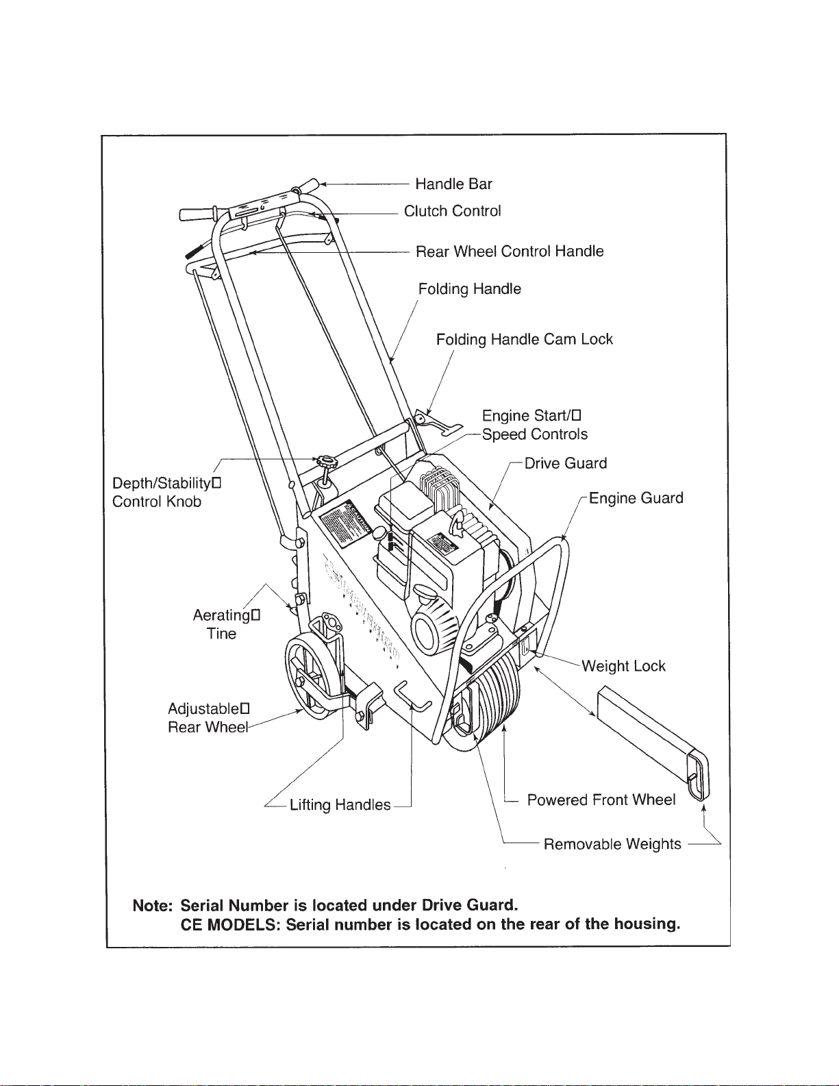
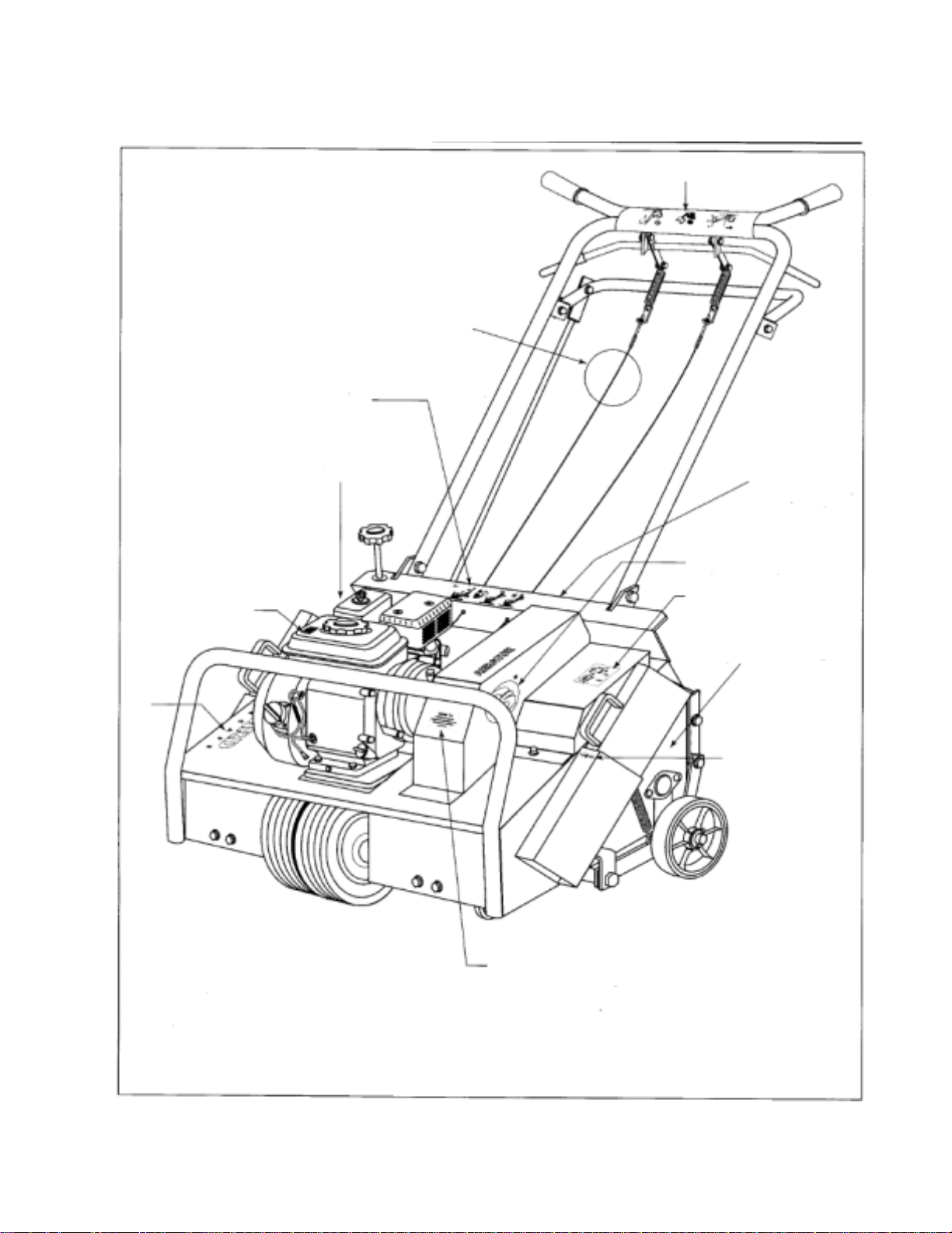
MODEL 424 - FEATURES AND CONTROLS
Figure 1
4
Operator’s Guide
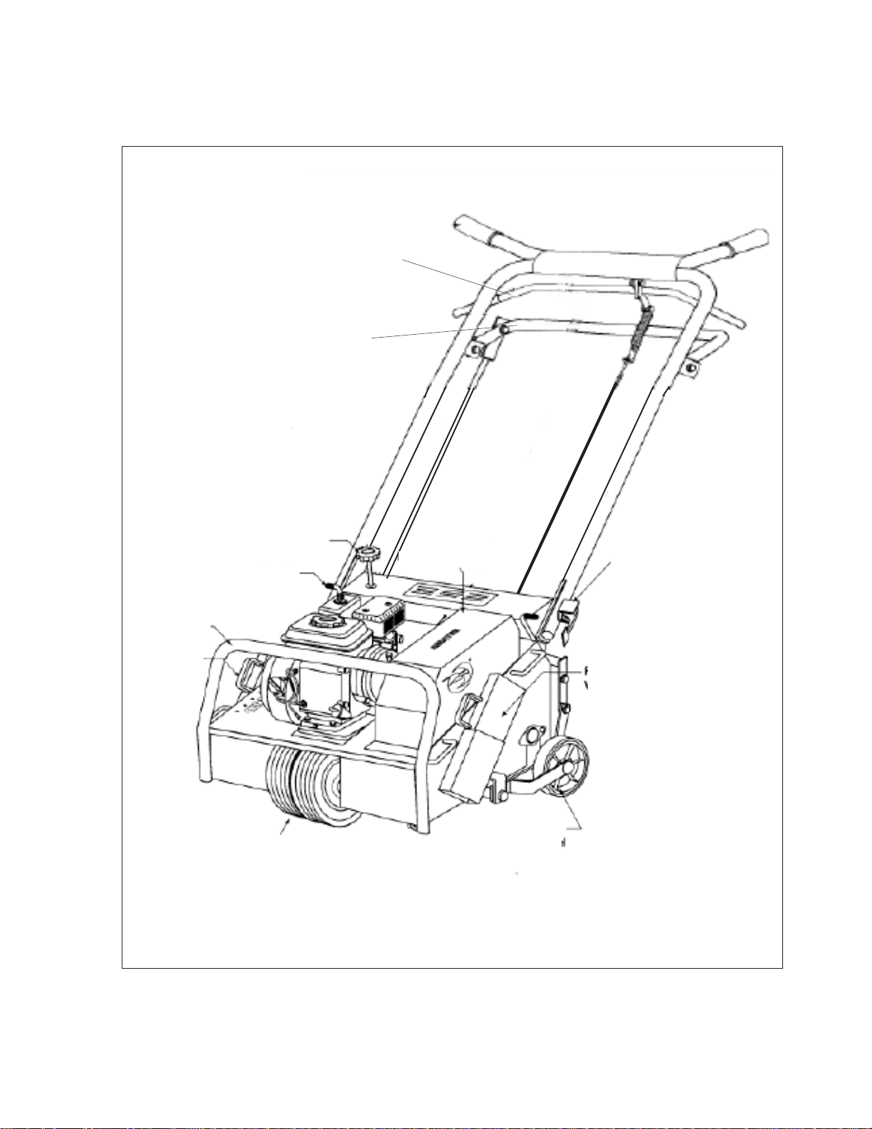
MODEL 530A - FEATURES AND CONTROLS
Clutch Control
Rear Wheel
Control Handle
Engine
Guard
Removable
Weight
Note: Serial number is located on the rear of the housing.
Depth/Stability
Control Knob
Handle
Stop s
Powered
Front Wheel
Drive Guard
Folding Handle
Locking Cam
Removable
Weight
Adjustable
Rear Wheel
Figure 2
5
Operator’s Guide
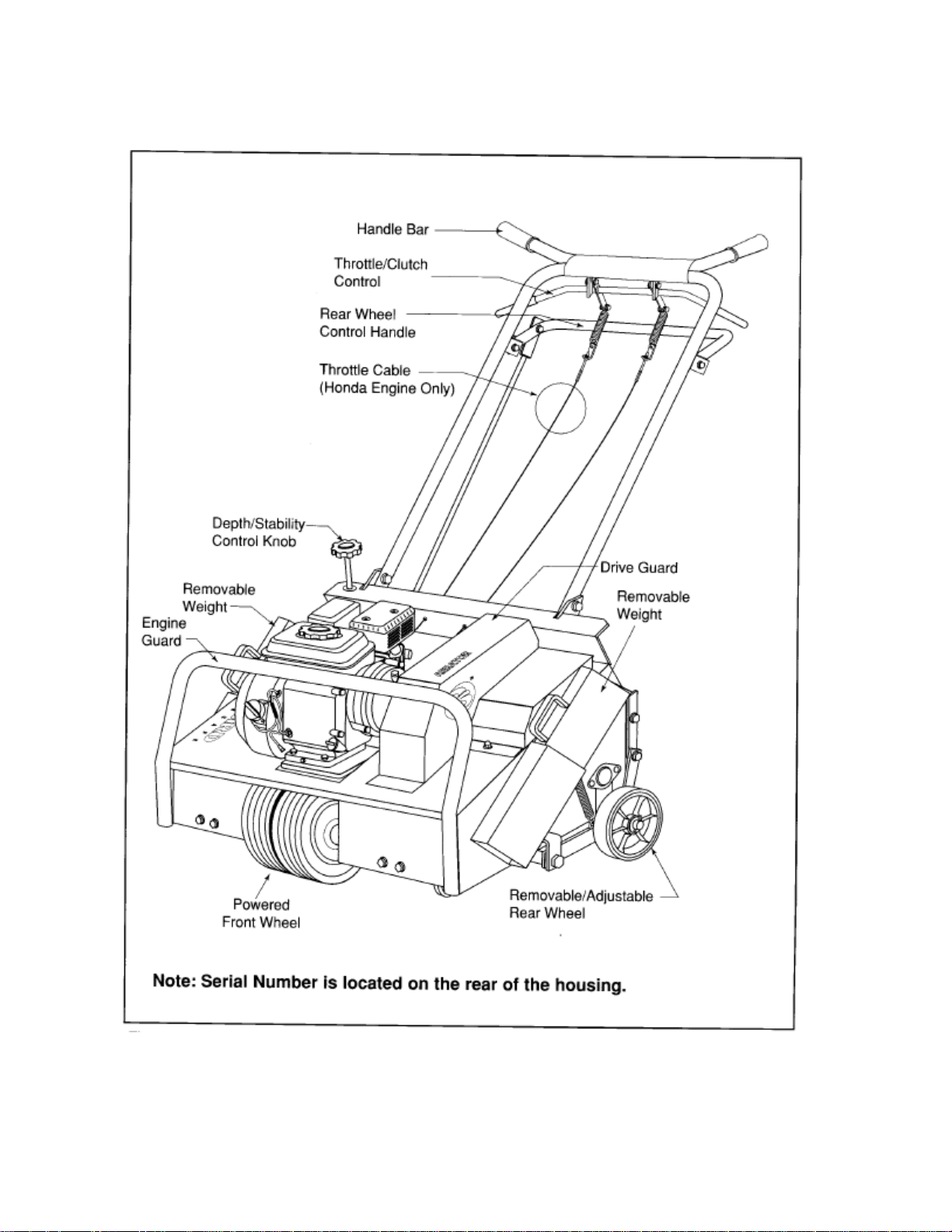
MODEL 742 - FEATURES AND CONTROLS
Figure 3
6
Operator’s Guide
GENERAL INFORMATION
This manual will assist you in the safe operation
and proper maintenance of your Husqvarna
equipment. Read it thoroughly before attempting
to operate the machine. Call your dealer or
Husqvarna if additional information is required.
The following safety symbols are used
throughout the manual to alert you to information
about unsafe actions or situations:
DANGER indicates immediate hazards that
may result in severe injury or death.
WARNING indicates unsafe actions or
situations that may cause severe injury, death
and/or major equipment or property damage.
CAUTION indicates unsafe actions or
situations that may cause injury, and/or minor
equipment or property damage.
This equipment should not be modified without
the manufacturer’s prior written authorization.
Doing so may not only affect the equipment’s
performance and durability , but also create
safety hazards for the operator and the
surroundings. Warranty will be void if changes
are made to the equipment without the
manufacturer’s prior written authorization.
SAFETY PROCEDURES
DO:
• Read all maintenance and service instructions
before attempting work.
• Read engine manufacturer’s operating and
maintenance instructions.
• Remove spark plug wire before commencing
service.
• Inspect lawn to be aerated and remove rocks,
wire, string and other objects that might present
hazard before starting.
• Indentify and mark all ground objects to be
avoided, such as sprinkler heads, stakes, water
valves, clothes line anchors, etc.
• Use machine for lawn aeration only .
• Keep unsupervised children away from the
equipment.
• Adopt safe lif ting and moving techniques when
loading/unloading and moving the equipment.
• Make sure all decals are in place.
DO NOT:
• Do not run engine while servicing.
• Do not use on any surface other than grass.
• Do not operate on slopes exceeding 35%
grade.
• Do not place hands or feet near moving or
rotating parts.
• Do not lift Model 424 alone.
• Do not lift Model 530A.
• Do not lift Model 742
• Do not run engine in an unventilated space.
• Do not run engine while servicing. Remove
spark plug wire before commencing service.
• Do not smoke or allow open flames or sparks
near unit, and always stop the engine when
refueling
• Do not remove guards when operating.
• Do not modify this equipment.
• Do not use this equipment for purposes other
than lawn aeration.
7
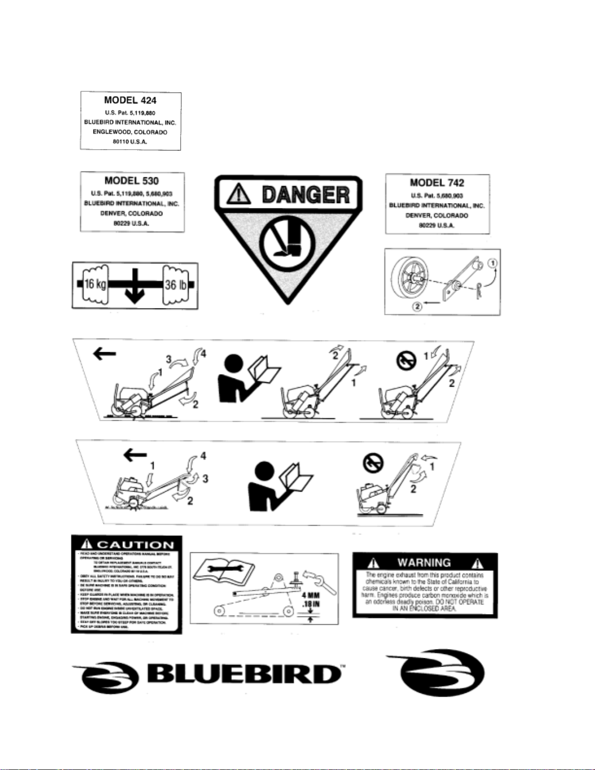
SAFETY AND INSTRUCTION DECALS
The following decals are found on Model 424,530 and 742 aerators. If any are missing or not
legible, replace them before operating aerator.
8343 Decal kit, Model 424
7630 Decal kit, Model 530A
7404 Decal kit, Model 742
A - Model 424 only (1 EA)
B - Model 530A only (1 EA)
D - Models 424, 530A & 742 (2
EA)
F - Models 424, 530A & 742 (1
EA)
G1 - Model 530A (1 EA)
C - Model 742 only (1 EA)
E - Model 742 only (2 EA)
H - Models 424, 530A & 742 (1 EA)
K - Models 530A & 742 (1 EA)
424 (2 EA)
G2 - Model 424 & 742 (1 EA)
I - Models 424, 530A & 742 (1 EA)
8
J - Models 424, 530A & 742 (1 EA)
DECAL PLACEMENT - MODELS 424, 530A AND 742
Throttle Cable
(Model 742 with
Honda only)
G1
G2
H (on deck
behind
engine)
K (for Models 424 & 742
logo only)
I
J
K
F (on back
of housing
over tine
rotor)
E (for Model 742)
D
A (for Model 424)
B (for Model 530A)
C (for Model 742)
Figure 3
9
Operator’s Guide
ASSEMBLY INSTRUCTIONS
Model 424
1. Remove wooden blocks. Note: Watch for nails
and wood splinters. Wear eye protection.
2. Carefully cut open side of carton.
3. Lawn Aerator 424 is shipped with handle
folded. Rear wheel control handle strapped
together with the clutch control. First cut
straps, then unfold handle. Lock handle in
position using the cam lock lever.
Model 530A
1. Wear eye protection. Remove wooden blocks.
NOTE: Watch for nails and wood splinters.
2. Carefully cut open side of carton.
3. Lawn Aerator is shipped with handle folded.
Lock handle in position using the cam lock
lever.
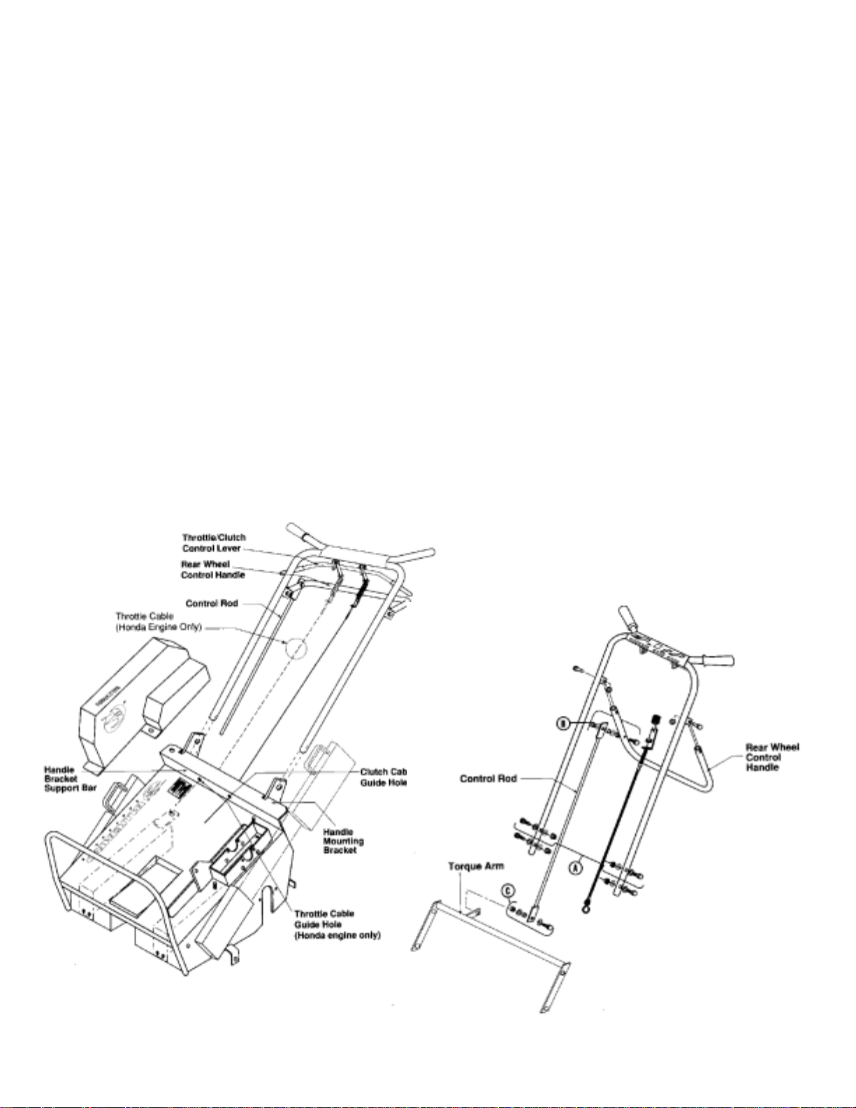
Model 742
1. Wear eye protection. Remove wooden blocks.
NOTE: Watch for nails and wood splinters.
2. Carefully cut open side of carton.
3. Lawn Aerator is shipped with the handle
detached. Mount the handle using 2 each ½”
wrenches.
(A) Slide handle onto handle mounting
brackets (see Figure 4).
(B) Insert and tighten fasteners, which
are located on handle mounting
brackets (see Figure 5-A). For further
detail on assembly, see parts section.
4. Connect top of control rod to rear wheel
control handle with fasteners located on rear
wheel control handle (see Figure 5-B) For
further detail on assembly, see parts manual.
5. Connect bottom of control rod to
of lever on the torque arm using the fastener
assembly (see Figure 5-C).
6. Run the clutch cable through the guide hole in
the handle bracket support bar located at rear
of the deck (see Figure 4).
7. Att ach end of cable to the “S” hook located on
the belt idler pulley .
8. (Honda Engines Only) Connect the throttle
cable by attaching the throttle spring to the
throttle/clutch control lever. (see Figure 4)
OUTER side
Figures 4
Figures 5
10
AERATION TIPS
Operating Instructions
Should I water before aerating?
Best aerating condition is a soft and moist
ground. If you are unsure of the ground
conditions, as in soil with high clay content, a
simple test will determine whether it is
necessary to water before aerating. Using a
garden hand spade or a large screw driver , you
should be able to drive the tool in the ground 2 to
3 inches with little effort. If you are unable to do
so, then watering the lawn a day before aerating
is necessary.
When should I use the removalole weights?
Soil conditions will dictate whether extra
machine weight is needed for effective coring
action. The weights are provided to give you
added control, and greater tine penetration.
BEFORE YOU START
1. Make sure that engine oil is at engine
manufacturer’s recommended level (refer to
engine manual). Be sure gear reduction oil is
at engine manufacturer’s recommended level.
Make sure the machine is level when filling
with oil.
2. With the folding handle in its operating
position, lock the handle cam lock (Models
424 & 530A only).
3. Rear wheel control handle must be pulled up
so rear wheels are all the way down.
4 Insert weights if needed.
5. Be sure handle is properly mounted.
6. Test clutch handle to insure clutch releases
freely.
7. The engine top speed is preset by the engine
manufacturer. Consult the engine
manufacturer’s manual for directions to
adjust the governor and carburetor if speed is
not within correct range.
8. 742 Honda Engines Only: The throttle cable
has been installed by the factory , however
throttle spring needs to be connected to
throttle/clutch control lever (see Figure 4).
AERATING
1. Start engine and adjust throttle setting to
provide a comfortable walking speed and
maintain control of the equipment at all times.
2. Adjust depth control knob (see Figure 1 or 2)
to desired depth. Coring depth decreases by
turning the knob clockwise.
NOTE: by raising the rear wheels all the way
up (to obtain maximum coring depth) you will
reduce the unit’s stability but increase length
of core.
3. Push down the rear wheel control handle to
lower aerating tines into the ground (rear
wheels will rise).
4. Push down on handle bar for better tine
penetration and maneuverability (front wheel
will rise).
5. Engage clutch control.
6. Adjust engine throttle setting, if needed, for
comfortable speed.
7. To stop, release clutch control.
CAUTION!
Be sure clutch cable is routed properly.
CAUTION!
NEVER cross hard objects or surfaces
(sidewalks, driveways, stepping stones,
etc.) with tines down.
11
Operating Instructions
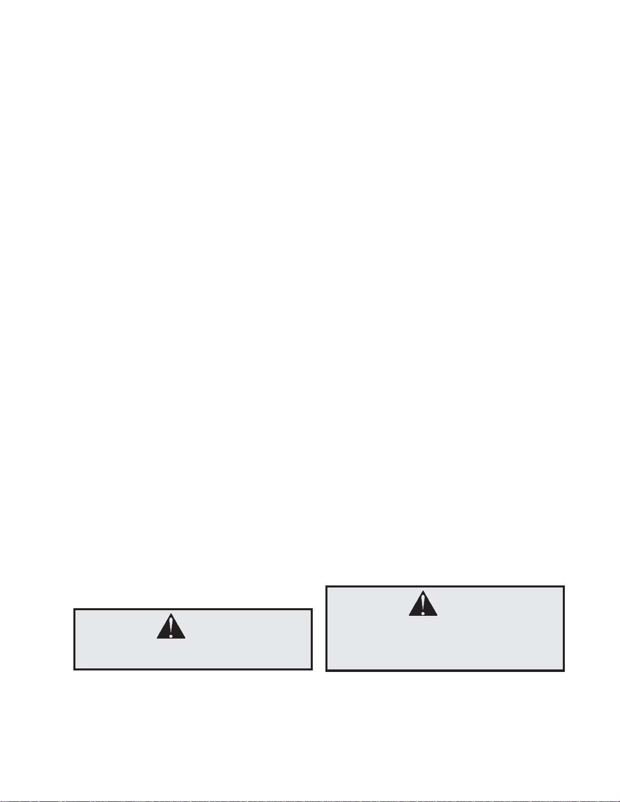
THROTTLE CABLE ADJUSTMENT. Model 742 (Honda Engine Only)
1. Start engine and allow it to reach operating
temperature.
2. Adjust the throttle cable at the adjuster
bracket by turning the adjuster nut. Tightening
will increase engine speed, loosening will
reduce engine speed.
NOTE: A properly adjusted throttle will slightly
increase engine speed as the clutch engages.
• If the clutch engages too soon, the engine
will stall.
• If the engine speed is too high, the gradual
controlled start is lost.
Figure 6
REAR WHEEL ADJUSTMENT
The rear wheel depth/stability control knob (see
Figure 7) allows adjustment for better stability
and maneuverability by turning knob clockwise.
Adjusting for depth by turning knob counter
clockwise determines the length of the cores
pulled in the following ways:
(A) The rear wheels can be adjusted to the
level you desire so you can control the
penetrationof the tines to within a
fraction of an inch. The length of the
cores pulled can be
controlled accordingly .
(B) With the rear wheels adjusted to the full
up position, you will obtain maximum
tine penetration. Pushing down on the
machine’s handle bars will put most of
the weight of the machine on the tines.
In this configuration you will pull the
longest cores. (Front wheel will rise).
Figure 7
12
Operating Instructions
NOTE: Adjusting for greater st ability will shorten
the length of the cores you pull. You will gain
greater side-to-side stability (see below
“Operating on Hills.” Adjustment s for greater
stability will also improve maneuverability during
aeration.)
TURNING AND MANEUVERING THE AERATOR
Gradual maneuvering while aerating can be
accomplished by simply guiding the machine.
We recommend that you adjust your engine’s
speed control to allow for a comfortable walking
speed. This will also help you maintain complete
control while working in tight spaces. Adjusting
for more stability (with the rear wheels lowered,
reducing tine penetration) will make turning
easier.
When reversing direction or making sharp turns
two methods of turning can be used. Select the
safest and most comfortable method for the
conditions you face:
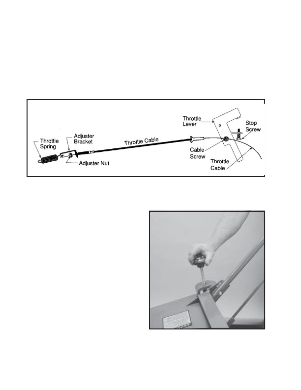
OPERATING ON HILLS
WARNING!
DO NOT operate on hills exceeding 35%
grade.
Figure 8
(A) Release clutch control handle, pull up rear
wheel control handle, then pivot machine on
rear wheels to turn.
(B) Release clutch control handle, lift handle bar
and pivot machine on front wheel.
WARNING!
This method is NOT recommended when
operating on hills. (See next section.)
This unit is not designed to be used on steep
slopes. Be aware that when operating on hills
the
tilt of the aerator will cause the machine’s center
of gravity to shift to the downhill side of the
machine. Under these circumstances you may
experience:
(A) The need to exert a greater effort to
steer and maintain the balance of the
machine.
(B) Uneven tine penetration, when
operating across a hill. Due to the shifted
center of gravity
the downhill tines will penetrate to the
maximum depth, while uphill tines may
not.
WARNING!
In extreme situations (very steep hills)
the machine may be so unbalanced, that
it may present the danger of rolling over.
13
Operating Instructions
When operating on hills you should
consider the following:
(A) Operate the machine up and down the
hills rather than across them.
(B) Use the rear wheel depth/stability control
knob to set the rear wheels for extra
stability. This can be a great benefit
when you do choose to run the aerator
across a hill. An added benefit of using
the rear wheel depth control when
aerating across a hill is that you will
improve the consistency of the cores
pulled from the uphill tines when
compared to those pulled by the
downhill tines.
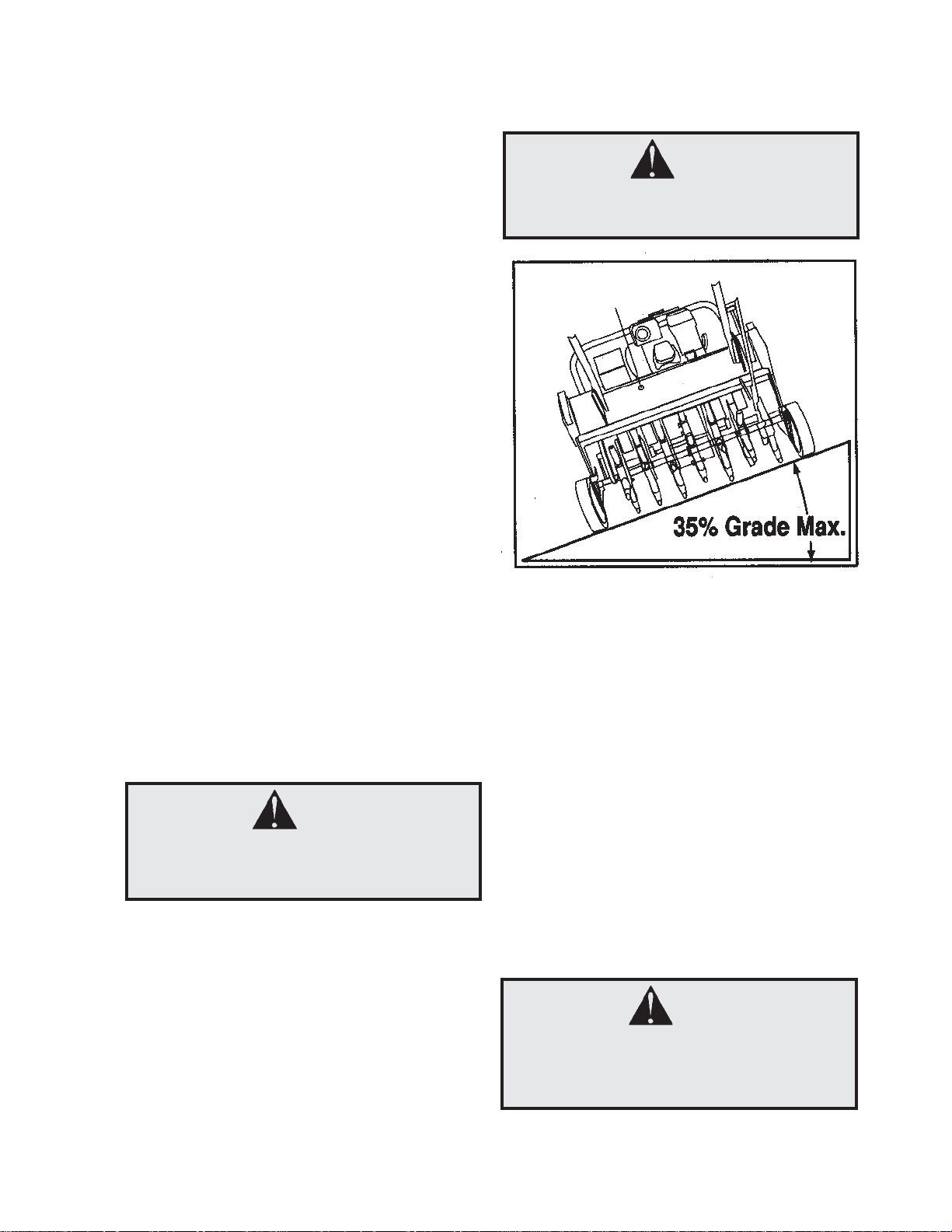
(C) Removing the downhill weight reduces
roll-over risk and maintains consistent
core plug length. (See Figure 9)
(D) Remove remaining weight from downhill
side to uphill side after each pass when
operating across hills.
WARNING!
NEVER disengage tines from ground
when travelling up or down hill. ONLY
disengage on flat surface.
TRANSPORTING THE BLUEBIRD
AERATOR
MODEL 424
The BlueBird 424 Aerator has three convenient
features to assist you in transporting the unit in
your pick-up truck, van and even in some car
trunks. Those features are: removable weights,
a folding handle and convenient lifting handles on
the sides of the machine. The features are
provided for your optional use and can be of
great benefit when required.
Removable Weights
• Unlatch weight locks.
• Grab weight handles and pull the weights
from the machine.
Note: Weight 36 lb/16 kg each.
Folding Handle
• Release handle cam lock.
• Fold handle forward over the engine until it
is resting on the engine guard.
Lifting Handles
Lifting handles are located on both sides of the
aerator, to allow two people to lif t the unit.
CAUTION!
Avoid back or muscle injury! Use safe
lifting techniques, DO NOT exceed your
physical limitatons. DO NOT attempt to lift
ALONE. Weight 193 lb/88 kg w/o weights.
Figure 9
MODELS 530A AND 742
The removable weights are for side hill stability
and tine penetration as applicable.
CAUTION!
DO NOT lift aerators.
With the weights in place, these models are
designed for easy loading and unloading on
ramps and trailers. The treaded front wheel
provides increased control during transport. Use
engine power to load unit.
14
 Loading...