

Page 1

Operating Instructions and Parts Manual SBS50 Boost
Please read and save these instructions. Read carefully before attempting to assemble, install, operate
or maintain the product described. Protect yourself and others by observing all safety information.
Failure to comply with instructions could result in personal injury and/or property damage! Retain
The Professional’s Line
instructions for future reference.
Pressure Booster System
Description
The booster is designed to increase
General Safety
Information
water pressure from municipal sources
or private water systems. The unit is
equipped with a 1/2 HP, 120 volt singlephase motor. Use only to pump clear
water. The system includes the pump,
control box, pressure sensing switch,
bladder tank, and fl ow sensing switch.
Do not attempt to
use product at 240
volt. Only 120 volt is allowed.
Unpacking
After unpacking the pressure booster system, carefully inspect for any damage that
may have occurred during transit. Check
for loose, missing or damaged parts.
Safety Guidelines
This manual contains information that is
very important to know and understand.
This information is provided for SAFETY
and to PREVENT EQUIPMENT PROBLEMS.
To help recognize this information,
observe the following symbols.
Danger indicates an
imminently hazardous
situation which, if not avoided, will result
in death or serious injury.
Warning indicates a
potentially hazardous
situation which, if not avoided, could
result in death or serious injury.
Caution indicates a
potentially hazardous
situation which, if not avoided, may
result in minor or moderate injury.
Notice indicates
important
information, that if not followed, may
cause damage to equipment.
CALIFORNIA PROPOSITION 65
This product or its
contain chemicals known to the State
of California to cause cancer and birth
defects or other reproductive harm. Wash
hands after handling.
GENERAL SAFETY
1. Read the instruction manual included
with the product carefully. Be
thoroughly familiar with the controls
and the proper use of the equipment.
2. Know the pump application,
limitations and potential hazards.
Always install a
to match the system pressure rating and
the maximum fl ow rate.
Do not use to pump
explosive fl uids such as gasoline,
fuel oil, kerosene, etc. Do not use in
explosive atmospheres. Pump should
only be used with liquids compatible
with pump component materials. Failure
to follow this warning can result in
personal injury and/or property damage.
Disconnect power
pressure from the system before
attempting to install, service, relocate
or perform any maintenance. Lock the
power disconnect in the open position.
Tag the power disconnect to prevent
unexpected application of power.
3. Drain all liquids from the system
before servicing.
4. Secure the discharge line before
starting the pump. An unsecured
discharge line will whip and possibly
cause personal injury and/or
power cord may
pressure relief valve
fl ammable or
and release all
Figure 1
property damage.
5. Periodically inspect pump and
system components. Perform routine
maintenance as required (See
Maintenance).
6. PERSONAL SAFETY:
a. Wear safety glasses at all times
when working with pumps.
b. Keep work area clean,
uncluttered and properly lighted.
Replace all unused tools and
equipment.
c. Keep visitors at a safe distance
from work area.
d. Make the workshop childproof
use padlocks, master switches
and remove starter keys.
7. Do not pump chemicals or corrosive
liquids. Pumping these liquids
shortens the life of the pumps seals
and moving parts and will void the
warranty.
8. Complete pump and piping system
MUST be protected against below
freezing temperature. Freezing
temperatures could cause severe
damage and void the warranty.
9. Do not run the pump dry or damage
will occur and will void warranty.
REMINDER: Keep your dated proof of purchase for warranty purposes! Attach it to this manual or fi le it for safekeeping.
© 2010 Blue Angel™ Pumps For parts, product & service information
visit www.blueangelpumps.com
341602-002 7/10
Page 2
Operating Instructions and Parts Manual SBS50 Boost
General Safety
Information
(Continued)
Risk of electrical
shock. This pump is
designed for indoor installation only.
All wiring should
be performed by a
licensed or certifi ed electrician.
10. For safety, the unit must be
connected to a grounded circuit
equipped with a ground fault
interrupter device.
11. Before installing the pump, have the
electrical outlet checked by a licensed
or certifi ed electrician to make sure
the outlet is properly grounded.
12. Make sure the line voltage and
frequency of electrical current supply
agrees with the motor wiring.
Do not attempt to
use product at 240
volt. Only 120 volt is allowed.
13. Do not attempt repairs to the electric
motor. All repairs to the motor
must be completed at a licensed or
certifi ed electrical motor repair shop.
Do not touch an
operating motor.
Modern motors are designed to operate
at high temperatures.
14. Avoid kinking electrical cord and protect
from sharp objects, hot surfaces, oil and
chemicals. Replace or repair damaged or
worn cords immediately.
Disconnect power and release all
pressure from the system before
attempting to install, service, relocate
or perform any maintenance. Lock the
power disconnect in the open position.
Tag the power disconnect to prevent
unexpected application of power.
15. Keep fi ngers and foreign objects away
from ventilation and other openings. Do
not insert any objects into the motor.
Risk of electric shock!
Never connect the
green (or green and yellow wire) to a
live terminal!
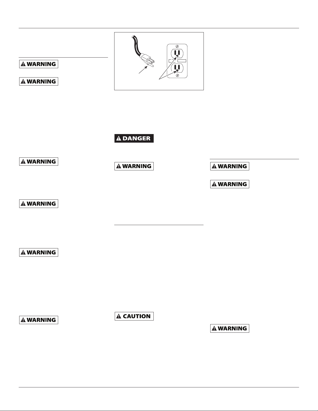
16. To reduce the risk of electrical shock,
the pump should be plugged directly
into a properly installed and grounded
3-prong grounding type receptacle, as
shown in Figure 2. The green (or green
and yellow) conductor in the cord is
the grounding wire. The motor must
be securely and adequately grounded
for protection against shock.
www.blueangelpumps.com
RESET
TEST
Grounded
Pin
Figure 2
Grounded Outlet
17. Where a 2-prong is encountered,
replace the plug with a properly
grounded 3-prong receptacle in
accordance with the National Electrical
Code, local codes and ordinances.
To ensure a proper ground, the
grounding means must be tested by a
licensed or certifi ed electrician.
Do not handle pump
wet hands, when standing on a wet or
damp surface or when standing in water.
Fatal electrical shock could occur.
Pump motor is
automatic resetting thermal protector
and may restart unexpectedly. Protector
tripping is an indication of motor
overloading because of operating pump
at low heads (low discharge restriction),
excessively high or low voltage,
inadequate wiring, incorrect motor
connections or defective motor or pump.
or pump motor with
equipped with an
Installation
LOCATION
Select a location as close to the water supply
as possible. Be sure to comply with any state
or local codes regarding the placement
of the pump. The equipment must be
protected from the elements. A basement
or heated pump house is a good location.
Make sure the pump has proper ventilation.
The temperature surrounding the pump
is not to exceed 100°F (40°C) or nuisance
tripping of the motor overload may occur.
PIPING
Piping may be copper, steel, rigid PVC
plastic or fl exible polyethylene plastic.
Flexible pipe is not
recommended on
suction pipe (inlet pipe). Flow sensor is
designed for 1” NPT connection.
The pipe must be clean and free of rust or
scale. Apply Tefl on
to the 1” male NPT pipe threads and install
the switch into the piping system. Thread the
fl ow switch onto the male pipe thread until
hand-tight. Tighten pipe 1 additional turn. If
improper seal results, continue turning pipe
into unit 1/4 turn increments. Do Not Exceed
1 Additional Turn All connections must be air
tight to insure normal operation.
®
thread tape or sealant
Slope all inlet piping upwards towards
the pump to prevent trapping air.
IMPORTANT: Pump is built to handle
clear water only; it is not designed to
handle water containing sand, silt or
other abrasives.
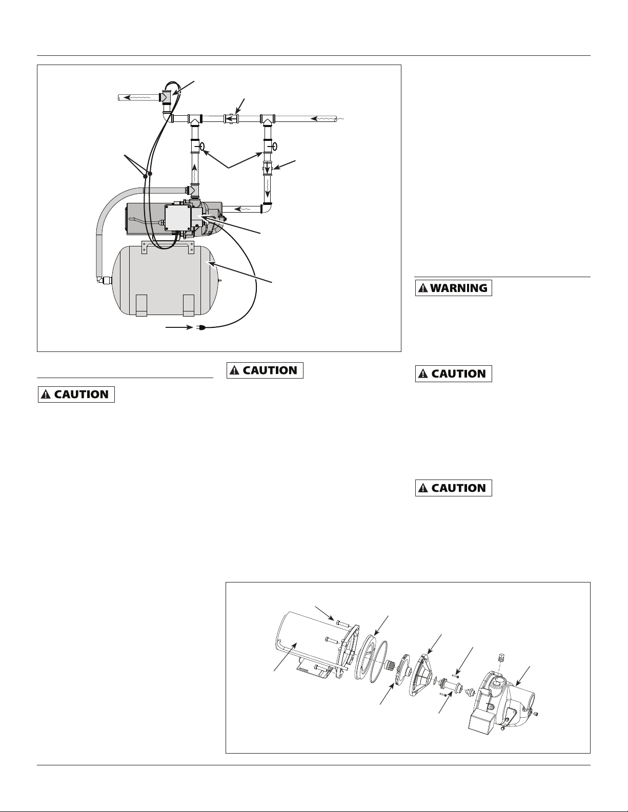
1. Refer to Figure 3
for typical
installations.
2. Bolt pressure booster system to a
secure foundation.
3. Locate the pump so that there will
always be a positive supply of water
to the pump (See Figure 3).
4. For service convenience, the installer
is recommended to add gate valves
and unions as needed to provide for
easier maintenance.
5. Pressure gauges on the inlet and
outlet, provided by the installer, are
recommended to show if suffi cient
water is being supplied to the pump
and to show service pressure.
Electrical
Risk of electrical
shock. This pump is
designed for indoor installation only.
Disconnect power
and release all pressure from the system
before attempting to install, service,
relocate or perform any maintenance.
IMPORTANT: Do not use an extension
cord or splice wires. Joints should be
made in an approved junction box. If the
above information is confusing, consult
a licensed electrician.
Your unit is supplied with a pressure
switch, fl ow sensor and a control box.
The only wire connection needed is to
plug the two red wires from the control
box into the two red wires on the fl ow
sensor (See Figure 3).
MOTOR PROTECTION
This motor has built in thermal protection.
The overload protects the motor against
burnout from overload of low voltage,
high voltage and other causes. The device
is automatic and resets itself once the
temperature has dropped to a safe point.
Frequent tripping of the device indicates
trouble in the motor or power lines and
immediate attention is needed.
Never examine,
or touch the motor before disconnecting the main electrical supply switch.
The thermal device may have opened the
electrical circuit. The pump motor should
be equipped with a correctly fused disconnect switch to provide protection. Consult
local or United States National Electrical
Codes for proper fuse protection.
make wiring changes
2
Page 3
Operating Instructions and Parts Manual SBS50 Boost
Flow
Switch
To Service
Flow Switch
Connections
120 VAC Plug
Figure 3 - Typical installation
Operation
Unit must be full of
fl uid before
operating. Do not run dry or against a
closed discharge. Do not pump dirty water
or abrasive liquids. To do so will cause the
pump failure and will void the warranty.
VALVES
The inlet and outlet isolation valves
should be in the full open position.
PRIMING
NOTE: Before starting the pump it
is absolutely necessary that both
the pump and the inlet pipe be
completely fi lled with water.
PRESSURE BOOST INSTALLATIONS
Priming is automatic when pump is
connected to a pressure source such as a
hydrant or city main. (See Figure 3).
1. Open valves or nozzle on inlet and
discharge side of pump.
2. Open a faucet nearest the booster
unit. Plug pump into outlet. When
the water fl ow from the faucet
reaches one gallon per minute, or
greater, the pump will automatically
start. Keep the faucet open for
approximately 30 seconds to relieve
trapped air in the line. When the
faucet is closed, the pump will
continue to run until pressure
reaches 60 psi.
NOTE: Orient Flow Switch as indicated
Check Valve
Municipal
Water
Check Valve
Isolation
Valves
Pressure
Switch
Tank
NOTE: “T”’s, Elbows,
and Isolation Valves
are not included
The pressure switch
is factory set at 50
psi and must not be changed.
3. If you installed a pressure gauge at
the pump inlet, a reading of 2 psi
minimum should show whenever the
pump is in operation. This reading
ensures that there is an ample supply
of water into the pump inlet housing.
4. The controller, fl ow sensor and
pressure switch continuously
monitor water pressure and fl ow.
The system automatically turns the
unit off if pressure reaches 50 to
53 psi. The control package also
protects the unit from dry run by
shutting down if water usage drops
below 1 gallon per minute.
Cap Screws
Motor
Impeller
Figure 4
MOTOR/PUMP ROTATION
1. The motor rotates in a counter
clockwise rotation when facing the
pump end and cannot be reversed.
START-UP PROCEDURE
Once the preceding instructions have
been completed, the unit is ready for
normal operation.
1. During the fi rst few hours of
operation, inspect the pump, piping
and any auxiliary equipment used in
connection with the unit for leaks,
excessive vibration or unusual noises.
2. The booster unit will turn on and
off automatically, based on water
usage.
Maintenance
Disconnect power
and release all
pressure from the system before
attempting to install, service, relocate
or perform any maintenance. Lock the
power disconnect in the open position.
Tag the power disconnect to prevent
unexpected application of power.
Protect the pump
from freezing during
winter conditions.
DRAINING THE PUMP
Drain openings are provided on all
models. To drain the pump:
1. Remove drain plug and prime plug
to vent the system.
REMOVING OLD SHAFT SEAL
Turn disconnect switch
to “off” position.
1. Open a faucet nearest the tank and
allow all water to drain from the
tank.
2. Remove the four cap screws holding
the pump housing (volute) to the
motor (Figure 4).
Seal Plate
Diffuser
Cap Screws
Pump
Housing
(Volute)
Venturi
www.blueangelpumps.com
3
Page 4
Operating Instructions and Parts Manual
SBS50 Boost
Operation (Continued)
3. Separate the pump housing (volute)
from the motor to expose the
diffuser and the seal plate.
4. Remove the two cap screws and
diffuser from the seal plate to
expose the impeller.
5. Remove the small end cap on the
end of the motor opposite the
impeller.
6. With a large screwdriver or
adjustable wrench, keep the shaft
from rotating and remove the
impeller by hand (standard right
hand thread). Be sure to hold onto
the seal plate when removing the
impeller from the shaft.
7. Remove the seal plate.
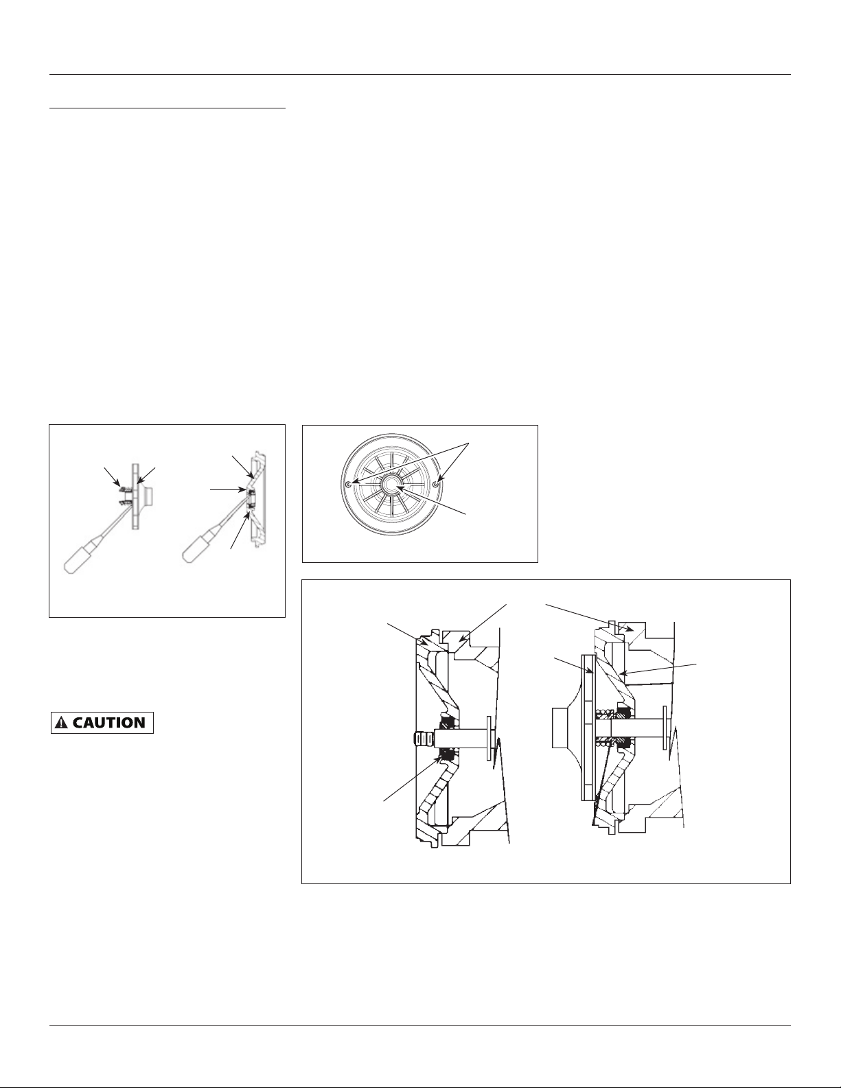
8. Pry the rotating shaft seal member
from the impeller (Figure 5).
Rotating
Shaft Seal
Member
Figure 5 - Removing Shaft Seal and
Ceramic Seat
Impeller
9. Push or pry the ceramic seat free
from the seal plate (Figure 5).
10. Remove loose particles from
impeller hub and seal plate.
Seal
Plate
Rubber
Seat Ring
Ceramic
Seat
1. Wet the inside of the seal cavity
on seal plate and the rubber cup
enclosing the new ceramic seat with
cooking oil. Be careful not to scratch
the ceramic surface of the seal seat
and push seat enclosed in rubber
into seal cavity on seal plate. Use a
cardboard washer to protect polished
surface when pushing against ceramic
seat with any object. Be sure to
remove cardboard washer.
2. Carefully slip seal plate over shaft.
Do not disturb seal position in
seal plate. The seal plate must be
orientated during assembly so the
two screw holes are on a horizontal
line across the motor shaft and the
(4) locating pins on the back of the
seal plate line up with the tabs on
the motor housing (Figure 6). This
placement should be done to ensure
proper draining and priming.
Screw
Holes
Motor
Shaft
Figure 6 - Seal Plate Replacement
Motor
Seal Plate
3. Place rotating shaft seal member in
position on impeller and press into
place. Take care not to press against
polished seal surface.
4. Position impeller on shaft and
tighten securely (Figure 7).
5. Secure diffuser to seal plate using the
two cap screws. Be sure the screws
are orientated on a horizontal line as
described in Step 2.
6. Carefully position pump housing
(volute) gasket over the diffuser
onto the seal plate. In all shallow
well applications care must be taken
that the o-ring is clean and properly
positioned on the venturi. Cleaning
and positioning makes a good seal
inside the diffuser when assembled.
7. Assemble the pump housing (volute)
to the motor using the four cap
screws. Be sure the pump housing
(volute) gasket is positioned
correctly and tighten the screws
securely.
NOTE: Shaft must rotate freely and
motor end cap should be secured before
operation.
Impeller
Seal Plate
INSTALLING NEW SHAFT SEAL
Before handling shaft
seal parts wipe hands
clean. Dirt or grease can damage the seal.
www.blueangelpumps.com
Seal Seat
Figure 7 - Motor Shaft
4
Seal Facing Must Be
Clean for Proper Seal
Page 5

Operating Instructions and Parts Manual
SBS50 Boost
Troubleshooting Chart
ELECTRICAL PRECAUTIONS - Before servicing a pump, always shut off the main power breaker and then unplug
the pump. Make sure you are not standing in water and are wearing insulated protective sole shoes. Under
fl ooded conditions, contact your local electric company or qualifi ed licensed electrician for disconnecting electrical service prior
to pump removal.
Symptom Possible Cause(s) Corrective Action
Pump won’t start or run
at full speed
Pump operates, but
delivers little or no water
Excessive noise while
pumping
Pump leaks 1. Worn mechanical seal (leaks at shaft) 1. Replace shaft (rotary) seal
1. Blown fuse or open circuit breaker 1. Replace fuse or close circuit breaker. See wire
chart for proper breaker/fuse size
2. AC power is OFF 2. Turn power on
3. Incorrect voltage 3. Low voltage
a. Voltage must be within ± 10% of motor rated
voltage. Check incoming voltage. Contact
power company
b. Motor voltage is set for 120V AC. System is
not designed for 240V service.
4. Defective motor 4. Replace motor
5. Pump internal components clogged/
worn/ damaged
1. Valves plumbed into system restricting
fl ow
2. In-line fi lter restricting fl ow 2. Check all in-line fi lters to be sure they are not
3. Low line voltage 3. See low line voltage corrective action (above)
4. Inadequate water supply to booster
pump
5. Undersized piping 5. Replace undersized piping
6. Leak on inlet side of system 6. Make sure connections are tight. Repair leaks as
7. Worn or defective pump parts or pump 7. Replace worn parts or entire plugged impeller.
8. Suction lift to great 8. Pump should be operated under fl ooded suction
9. Pump not primed 9. Prime pump. Make certain inlet pipe connections
1. Pump not secured to fi rm foundation 1. Secure properly
2. Piping not supported 2. Make adjustments
3. Restricted inlet line 3. Clean, correct, or eliminate restrictions
4. Cavitation (pumping marbles) 4. Increase inlet pipe size
5. Worn motor bearings 5. Replace motor
2. Damaged o-ring seals 2. Replace square ring rubber gasket
5. Replace worn parts or entire pump. Clean parts if
required
1. a. Check valves on pump inlet and discharge sides
of system. Be certain they are opened completely to allow fl ow to and from the pump.
b. Bleed trapped air in pump. (Normally due to
closed valve in discharge plumbing).
plugged or restricted
4. Check pressure on inlet side of booster to be sure
positive pressure is maintained to the booster
pump at all times
needed
Clean parts if required
only. See Corrective Action 4 above.
are tight and pump and pipe are full of water
www.blueangelpumps.com
5
Page 6
Operating Instructions and Parts Manual
SBS50 Boost
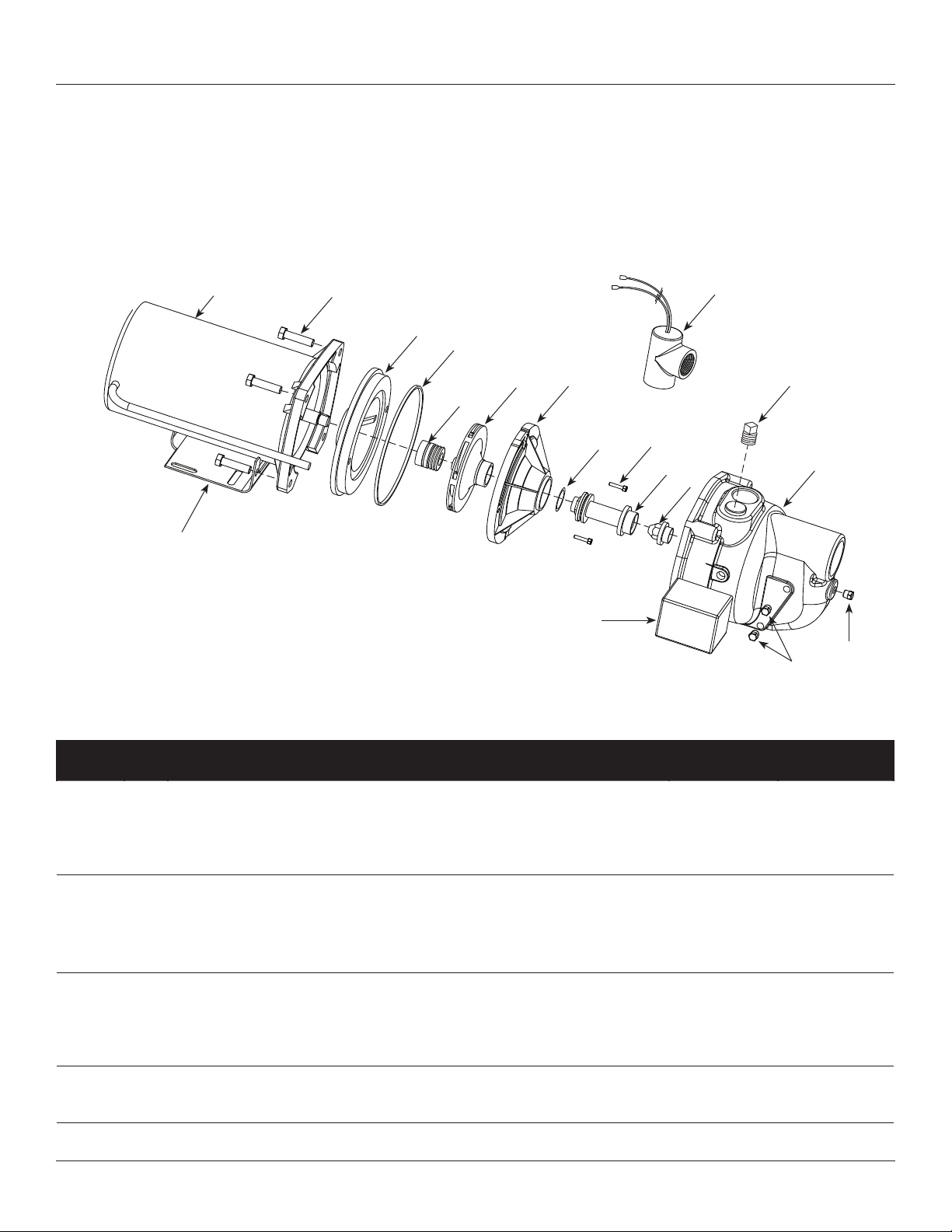
For Replacement Parts, call 1-888-636-6628
Please provide following information: Address parts correspondence to:
- Model number Blue Angel Pumps
- Serial number (if any) 101 Production Drive
- Part description and number as shown in parts list Harrison, OH 45030 U.S.A.
16
1
2
3
4
6
5
7
9
17
8
10
18
12
13
11
14
15
Ref.
No. Description
Part
Numbers Qty.
1 Motor 32059-001 1
2 Screw 16636-002
3 Seal plate 17145-001 1
4 • Square ring rubber gasket 17150-001 1
5 • Shaft seal assembly 56393 1
6 Impeller 23285-002 1
7 Diffuser 17148-001 1
8 Screw 67007-001
9 • O-ring 15557 1
10 Venturi 17151-002 1
11 Nozzle 15672 1
12 Pipe plug 3/4” 15921 1
13 Volute 56869-001 1
14 Pipe plug 1/4” NPT 16314-002 1
15 Pipe plug 1/8” NPT 15766-002 1
16 Base 23029-001 1
17 Pressure switch 30010-001 1
18 Flow switch 30048-001 1
• Repair kit (Includes #4, 5 and 9) 56874-001 1
www.blueangelpumps.com
6
Page 7

Operating Instructions and Parts Manual SBS50 Boost
Notes
www.blueangelpumps.com
7
Page 8

Operating Instructions and Parts Manual
SBS50 Boost
Limited Warranty
For two (2) years from the date of purchase, Blue Angel will repair or replace, at its option, for the original purchaser any part
or parts of its Sump Pumps or Water Pumps (“Product”) found upon examination by Blue Angel to be defective in materials or
workmanship. Please call Blue Angel (1-888-636-6628) for instructions or see your dealer. Be prepared to provide the model
number and serial number when exercising this warranty. All transportation charges on Products or parts submitted for repair
or replacement must be paid by purchaser.
This Limited Warranty does not cover Products which have been damaged as a result of accident, abuse, misuse, neglect,
improper installation, improper maintenance, or failure to operate in accordance with Blue Angel’s written instructions.
THERE IS NO OTHER EXPRESS WARRANTY. IMPLIED WARRANTIES, INCLUDING THOSE OF MERCHANTABILITY AND
FITNESS FOR A PARTICULAR PURPOSE, ARE LIMITED TO TWO YEARS FROM THE DATE OF PURCHASE. THIS IS THE
EXCLUSIVE REMEDY AND ANY LIABILITY FOR ANY AND ALL INDIRECT OR CONSEQUENTIAL DAMAGES OR EXPENSES
WHATSOEVER IS EXCLUDED.
Some states do not allow limitations on how long an implied warranty lasts, or do not allow the exclusions or limitations of
incidental or consequential damages, so the above limitations might not apply to you. This limited warranty gives you specific
legal rights, and you may also have other legal rights which vary from state to state.
In no event, whether as a result of breach of contract warranty, tort (including negligence) or otherwise, shall Blue Angel or
its suppliers be liable for any special, consequential, incidental or penal damages including, but not limited to loss of profit or
revenues, loss of use of the products or any associated equipment, damage to associated equipment, cost of capital, cost of
substitute products, facilities, services or replacement power, downtime costs, or claims of buyer’s customers for such damages.
You MUST retain your purchase receipt along with this form. In the event you need to exercise a warranty claim, you MUST
send a copy of the purchase receipt along with the material or correspondence. Please call Blue Angel (1-888-636-6628) for
return authorization and instructions.
DO NOT MAIL THIS FORM TO Blue Angel. Use this form only to maintain your records.
MODEL NO. _______________________ SERIAL NO. _______________________ INSTALLATION DATE _______________________
ATTACH YOUR RECEIPT HERE
www.blueangelpumps.com
8
Page 9

Instructions d’Utilisation et Manuel de Pièces SBS50 Boost
S’il vous plaît lire et conserver ces instructions. Lire attentivement avant de monter, installer, utiliser
ou de procéder à l’entretien du produit décrit. Se protéger ainsi que les autres en observant toutes
les instructions de sécurité, sinon, il y a risque de blessure et/ou dégâts matériels! Conserver ces
The Professional’s Line
instructions comme référence.
Système de surpresseur
Description
Le surpresseur est conçu pour augmenter
la pression d’eau du réseau d’alimentation
d’eau de sources municipales ou
privées. L’appareil est doté d’un moteur
monophasé de 1/2 HP et 120 volts. Utiliser
seulement pour pomper de l’eau claire.
Le système inclut la pompe, la boîte de
contrôle, l’interrupteur de manomètre,
le réservoir à parois souples et un
interrupteur de détection d’écoulement.
Ne pas essayer
d’utiliser le produit à
240 volts. Seulement 120 volts est permis.
Déballage
Dès que l’appareil est déballé, l’inspecter
attentivement pour tout signe de
dommages en transit. S’assurer de
resserrer tous les raccords, boulons, etc.
avant de le mettre en service.
Directives de Sécurité
Ce manuel contient de l’information
très importante qui est fournie pour
la SÉCURITÉ et pour ÉVITER LES
PROBLÈMES D’ÉQUIPEMENT. Rechercher
les symboles suivants pour cette
information.
Danger indique une
situation hasardeuse
imminente qui RÉSULTERA en perte de
vie ou blessures graves.
Avertissement in
dique une situation
hasardeuse potentielle qui PEUT résulter
en perte de vie ou blessures graves.
i Attention indique
une situation
hasardeuse potentielle qui PEUT résulter
en blessures..
Avis indique de
l’information
importante pour éviter le dommage de
l’équipement.
Généralités sur la
Sécurité
PROPOSITION 65 DE CALIFORNIE
Ce produit ou son
cordon peuvent
contenir des produits chimiques
qui, de l’avis de l’État de Californie,
causent le cancer et des anomalies
congénitales ou autres problèmes de
reproduction. Lavez-vous les mains après
la manipulation.
GÉNÉRALITÉS SUR LA SÉCURITÉ
1. Lire attentivement ces instructions
et directives. Manque de suivre ces
instructions peut résulter en blessures
graves et/ou en dégâts matériels.
2. Connaissez l’application de la pompe,
ses limites et tous les risques.
Toujours installer
une soupape de
sûreté correspondante à la classifi cation
de pression du système et au taux de
débit maximum.
Ne pas pomper
les liquides
infl ammables ou explosifs tels que
l’essence, l’huile à chauffage, le kérosène,
etc. Ne pas utiliser dans un atmosphère
explosif. Utiliser la pompe seulement avec
les liquides compatibles avec les matériaux
de fabrication de la pompe. Manque de
suivre cet avertissement peut résulter en
blessures graves et/ou en dégâts matériels.
Mettre hors
circuit et dissiper
toute la pression du système avant
d’essayer de monter, de déplacer ou
de procéder au service ou à l’entretien.
Verouiller le sectionneur de puissance
dans la position ouverte. Étiquetter le
sectionneur de puissance afi n d’éviter
l’alimentation inattendue.
3. Purger tous les liquides du système
avant de procéder au service.
4. Fixer la ligne de décharge avant le
démarrage de la pompe. Une ligne
Figure 1
qui n’est pas bien fixée pourrait
fouetter et causer des blessures
personnelles et/ou le dégât matériel.
5. Inspecter la pompe et les pièces
détachées du système périodiquement.
Procéder à l’entretien ordinaire au
besoin (Voir la section Entretien).
6. SÉCURITÉ PERSONNELLE:
a. Toujours porter des lunettes de
sécurité pendant l’utilisation d’une
pompe.
b. Garder l’endroit de travail pro-pre,
pas encombré et bien éclairé. Ranger
tous les outils et l’équipement dont
on ne se sert pas.
c. Garder les visiteurs à distance
respectueuse de l’endroit de travail.
d. Protéger l’atelier des enfants
en utilisant des cadenas et des
interrupteurs principals. Enlever les
clés de démarrage.
7. Ne pas pomper de produits chimiques
ni de liquides corrosives. Le pompage
de ces liquides peut raccourcir la durée
des joints et des pièces mobiles de la
pompe et niera la garantie.
8. Le système complet de pompe et de
tuyaux DOIT être protégé contre les
températures inférieures à zéro. Les
témpératures congélantes peuvent
causer le dommage sérieux et nieront
la garantie.
© 2010 Blue Angel™ Pumps
MÉMENTO: Gardez votre preuve datée d’achat à fi n de la garantie!
Joignez-la à ce manuel ou classez-la dans un dossier pour plus de sécurité.
341602-002 7/10
Page 10

Instructions d’Utilisation et Manuel de Pièces SBS50 Boost
Généralités sur la
Sécurité
9. Ne pas faire fonctionner la pompe
au sec, ceci l’endommagera.
Risque de choc
pompe est conçue seulement pour une
utilisation à l’intérieur.
Toute installation
effectuée par un électricien certifi é ou
diplômé.
10. Pour la sécurité maximum, le modèle
devrait être branché à un circuit
de terre équipé d’un appareil qui
protège contre le dérangement dû à
une mise accidentelle à la terre.
11. Faire instpecter la prise de courant par
un électricien diplômé ou certifié afin
d’assurer que la prise soit mise à la terre
correctement avant d’installer la pompe.
12. S’assurer que la tension de ligne et
que la fréquence de la source de
courant électrique soient compatibles
avec l’installation de fils du moteur.
Ne pas essayer
240 volts. Seulement 120 volts est permis.
13. Ne pas essayer de réparer le moteur
électrique. Toutes réparations du
moteur électrique doivent être
complétées à un atelier de réparations
de moteur certifié.
Ne jamais toucher
marche. Les moteurs modernes sont
conçus pour le fonctionnement aux
températures élevées.
14. Éviter le tortillement du cordon
d’alimentation et protéger le cordon
d’alimentation contre les objets
pointus, les surfaces chaudes, l’huile
et les produits chimiques. Remplacer
ou réparer les cordons endommagés
ou usés immédiatement.
Mettre hors tension
toute la pression du système avant
d’essayer d’installer, de réparer, de
déplacer ou de procéder à l’entretien.
Verrouiller le sectionneur de courant
en position ouverte. Étiqueter le
sectionneur de courant pour éviter toute
mise sous tension imprévue.
15. Garder les doigts et les objets à l’écart
des ouvertures telles que celles de
ventilation. Ne jamais introduire des
objets dans le moteur.
Risque de secousse
brancher le fi l vert (ou vert et jaune) à
une borne sous tension!
16. Pour réduire le risque de secousse
(Suite)
électrique. Cette
de fi ls doit être
d’utiliser le produit à
un moteur en
et ensuite dissiper
électrique! Ne jamais
Broche
de terre
Figure 2
électrique, la pompe devrait être
branchée directement dans une
prise de courant à 3 broches mise
à la terre et installée correctement
telle qu’indiquée sur la Figure 1. Le
fil conducteur vert (ou vert et jaune)
dans le cordon est le fil de terre. Le
moteur doit être mis à la terre avec
sûreté afin de protéger contre les
secousses électriques.
17. S’il y a une prise à 2 broches, remplacer
la prise avec une prise de courant à
3 broches mise à la terre correctement
conformément aux Code Électrique
National (National Electrical Code) et
aux codes et règlements locaux. Assurer
une mise à la terre correcte requiert
l’inspection par un électricien certifié
ou diplômé.
Ne pas manipuler
moteur de pompe avec les mains trempes,
si debout sur une surface trempe ou
humide ou debout dans l’eau. Ceci peut
résulter en secousse électrique mortelle.
Le moteur de la pompe
protecteur thermique à réenclenchement
automatique et peut se mettre en marche
sans avis. Le déclenchement du protecteur
indique le surcharge du moteur causé
par l’opération de la pompe avec une
restriction de décharge basse, tension
très élevée ou basse, installation de fi ls
incorrecte, branchements de moteur
incorrects ou moteur/pompe défectueux.
Montage
SITUATION
Choisir un site aussi près de l’alimentation
d’eau que possible. S’assurer de se conformer
à tous les codes d’état ou locaux portant sur
le placement de la pompe. L’équipement
doit être protégé des éléments. Un sous-sol
ou une station de pompage chauffée est
un bon endroit. S’assurer que la pompe est
bien ventilée. La température ambiante de
la pompe ne doit pas dépasser 40 °C (100 °F)
sinon il pourrait y avoir un déclenchement
intempestif de surcharge de moteur.
TUYAUTERIE
Les tuyaux peuvent être de cuivre,
d’acier, de plastique de PVC rigide ou de
plastique de polyéthylène fl exible.
TEST
Prise de courant
mise à la terre
la pompe ni le
est équipé d’un
RESET
Un tuyau fl exible
n’est pas recommandé
sur le tuyau d’aspiration (tuyau d’entrée).
Le détecteur d’écoulement est conçu pour
une connexion de 2,54 cm (1 po) NPT.
La tuyauterie doit être propre et libre de
rouille ou de tartre. Appliquer du ruban
de téfl on® ou du mastic aux fi lets du tuyau
de 2,54 cm (1 po) mâle NPT et installez
l’interrupteur dans le système de tuyauterie.
Enfi ler l’interrupteur de débit sur le fi let du
tuyau mâle jusqu’à ce qu’il soit bien serré à
la main. Resserrer le tuyau 1 d’un autre tour.
Si le joint n’est pas approprié, continuer
à tourner le tuyau en incréments de 1/4 de
tour. Ne pas dépasser 1 autre tour Toutes
les connexions doivent être étanches pour
assurer un fonctionnement normal.
Incliner tous les tuyaux d’entrée vers
le haut et vers la pompe pour éviter
d’emprisonner l’air.
IMPORTANT: La pompe est fabriquée
pour traiter l’eau propre seulement, elle
n’est pas conçue pour l’eau contenant
du sable, de la vase ou autres abrasifs.
1. Voir la fi gure 3 pour les installations
typiques.
2. Boulonner le système de surpresseur
à une base sécure.
3. Placer la pompe pour qu’il y ait
toujours une alimentation positive
d’eau à la pompe (voir la fi gure 3).
4. Pour la commodité du service, il est
recommandé à l’installateur d’ajouter
des vannes d’obturateur et des raccords
au besoin pour faciliter l’entretien.
5. On recommande des manomètres
d’entrée et de sortie, fournis par
l’installateur pour montrer s’il y a
assez d’eau fournie à la pompe et
pour montrer la pression de service.
Électricité
Risque de choc
électrique Cette
pompe est conçue seulement pour une
utilisation à l’intérieur.
Mettre hors tension
et ensuite dissiper
toute la pression du système avant
d’essayer d’installer, de réparer, de
déplacer ou de procéder à l’entretien.
IMPORTANT: Ne pas utiliser de rallonges
ni de fi ls épissurés. Les joints devraient
se faire dans une boîte de connexion
approuvée. Si l’information précédente
prête à confusion, consulter un
électricien agréé.
L’appareil est fourni avec un pressostat,
un détecteur d’écoulement et une
boîte de contrôle. La seule connexion
de fi l nécessaire est de brancher les
deux fi ls rouges de la boîte de contrôle
dans les deux fi ls rouges du détecteur
d’écoulement (voir la fi gure 3).
10 Fr
Page 11

Instructions d’Utilisation et Manuel de Pièces SBS50 Boost
Interrupteur
de débit
Vers le service
Connexions
d’interrupteur
de débit
Fiche de 120 V c.a.
Figure 3 - Installation typique
PROTECTION DU MOTEUR
Ce moteur a une protection thermique
intégrée. La surcharge protège le moteur
contre le grillage suite à une surcharge
de basse tension, haute tension et autres
causes. L’appareil est automatique et
se réinitialise après que la température
atteint un point sécuritaire. Des
déclenchements fréquents de l’appareil
indiquent un problème du moteur ou des
lignes de courant et il faut une attention
immédiate.
Ne jamais examiner,
changer les câbles ou
toucher le moteur avant de mettre le tout
hors tension à l’interrupteur principal.
L’appareil thermique pourrait avoir ouvert
le circuit électrique. Le moteur de pompe
doit être doté d’un sectionneur à fusibles
appropriés pour fournir la protection.
Consulter les codes d’électricité locaux ou
le United States National Electrical Code
pour la protection appropriée à fusibles.
Clapet de non-retour
Vannes
d’isolement
AMORÇAGE
REMARQUE : Avant de mettre la pompe
en marche, il faut absolument que la
pompe et le tuyau d’entrée soient
entièrement remplis d’eau.
INSTALLATIONS DES SURPRESSEURS
L’amorçage est automatique lorsque la
pompe est branchée à une source de
pression comme une bouche d’incendie ou
une conduite publique. (Voir la fi gure 3).
1. Ouvrir les vannes ou la buse du
côté de décharge et d’entrée de la
pompe.
2. Ouvrir un robinet le plus proche du
surpresseur. Brancher la pompe dans
une prise. Lorsque le débit d’eau du
robinet atteint quatre litres ou un
gallon à la minute ou plus, la pompe
démarrera automatiquement.
Fonctionnement
L’appareil doit
être plein de fl uide
avant de mettre en marche. Ne pas faire
fonctionner à sec ou contre une décharge
fermée. Ne pas pomper d’eau sale ou de
liquides abrasifs. Ceci mènerait à la défaillance
de la pompe et annulera la garantie.
VANNES
Les vannes d’isolement d’entrée et
de sortie devraient être en position
complètement ouverte.
Figure 4 - Joint d’Arbre
REMARQUE : Orienter
l’interrupteur de débit
comme indiqué
Eau
municipale
Soupape de
retenue
Manostat
Réservoir
REMARQUE : Les « T »,
les coudes et les vannes
d’isolement ne sont pas inclus
Vis d’Assemblage
Moteur
Turbine
Garder le robinet ouvert pendant
environ 30 secondes pour dégager
l’air emprisonné dans la conduite.
Lorsque le robinet est fermé, la
pompe continuera à fonctionner
jusqu’à ce que la pression atteigne
414 kPa (60 lb/po²).
Le pressostat est
réglé en usine à 345
kPa (50 lb/po²) et ne doit pas être modifi é.
3. Si l’on installe un manomètre à
l’entrée de la pompe, un relevé
d’au moins 14 kPa (2 lb/po²) devrait
apparaître lorsque la pompe est en
marche. Ce relevé assure qu’il y a
suffi samment d’eau dans le boîtier
d’entrée de la pompe.
4. Le contrôleur, le détecteur
d’écoulement et le pressostat
surveillent continuellement la
pression et le débit d’eau. Le système
éteint automatiquement l’appareil
si la pression atteint 345 à 365 kPa
(50 à 53 lb/po²). La trousse de
contrôle protège aussi l’appareil
de tout fonctionnement à sec en
s’arrêtant si l’usage d’eau tombe sous
quatre litres ou 1 gallon à la minute.
ROTATION DE POMPE/MOTEUR
1. Le moteur tourne dans une rotation
antihoraire lorsqu’il est face à
l’extrémité de la pompe et ne peut
pas être inversé.
PROCÉDURE DE DÉMARRAGE
Après avoir terminé les instructions
précédentes, l’appareil est prêt pour une
utilisation normale.
1. Durant les premières heures de
fonctionnement, inspecter la
pompe, la tuyauterie et tout autre
équipement auxiliaire utilisé avec
l’appareil pour tout signe de fuites,
vibrations excessives ou bruits
inhabituels.
2. Le surpresseur se mettra en marche
et s’éteindra automatiquement selon
l’usage d’eau.
Plaque
d’Etanchéité
Diffuseur
Vis d’Assemblage
Carter de
Pompe
(Volute)
Venturi
11 Fr
Page 12

Instructions d’Utilisation et Manuel de Pièces SBS50 Boost
Entretien
Mettre hors
tension et ensuite
dissiper toute la pression du système
avant d’essayer d’installer, de réparer,
de déplacer ou de procéder à l’entretien.
Verrouiller le sectionneur de courant
en position ouverte. Étiqueter le
sectionneur de courant pour éviter
toute mise sous tension imprévue.
Protéger la pompe du
gel pendant l’hiver.
DRAINER LA POMPE
Des ouvertures de drainage sont fournies
sur tous les modèles. Pour drainer la pompe:
1. Retirer le bouchon de vidange et
le bouchon de remplissage pour
ventiler le système.
RETIRER LE VIEUX JOINT
D’ÉTANCHÉITÉ DE L’ARBRE
Mettre le sectionneur
à la position « off »
(arrêt).
1. Ouvrir un robinet près du réservoir et
laisser toute l’eau sortir du réservoir.
2. Retirer les quatre vis d’assemblage
retenant le boîtier de la pompe
9. Pousser ou sortir et dégager le siège
de céramique de la plaque de joint
(fi gure 5).
10. Retirer les particules meubles du moyeu
d’impulseur et de la plaque de joint.
INSTALLER LE NOUVEAU JOINT
D’ÉTANCHÉITÉ DE L’ARBRE.
Avant de manipuler
de l’arbre, il faudrait se laver les mains.
La saleté ou la graisse peut endommager
le joint.
1. Mouiller l’intérieur de la cavité du joint
sur la plaque et le godet de caoutchouc
enfermant le nouveau siège de
céramique avec de l’huile de cuisson.
Attention de ne pas égratigner la
surface de céramique du siège du joint
et pousser le siège enfermé dans le
caoutchouc dans la capacité du joint sur
la plaque du joint. Utiliser une rondelle
de carton pour protéger la surface
polie en poussant contre le siège de
céramique avec tout objet. S’assurer de
retirer la rondelle de carton.
2. Glisser avec soin la plaque de joint sur
l’arbre. Ne pas déplacer la position du
joint dans la plaque de joint. La plaque
de joint doit être orientée durant
(volute) au moteur (fi gure 4).
3. Séparer le boîtier de la pompe (volute)
du moteur pour exposer le diffuseur et
la plaque de joint.
4. Retirer les deux vis d’assemblage et le
diffuseur de la plaque de joint pour
exposer l’impulseur.
5. Retirer les petit bouchon d’extrémité à
l’extrémité du moteur du côté opposé
de l’impulseur.
6. Avec un large tournevis ou une clé
Figure 6 - Replacement de Plaque
d’Etanchéité
ajustable, empêcher l’arbre de tourner
et retirer l’impulseur à la main (fi let
standard de main droite). S’assurer
de tenir la plaque de joint en retirant
l’impulseur de l’arbre.
7. Retirer la plaque de joint.
8. Sortir la section du joint de l’arbre
rotatif de l’impulseur (fi gure 5).
Plaque
d’Étanchéité
les pièces du joint
Trous de
Vis
Arbre de
Moteur
l’assemblage pour que les deux trous de
vis soient à l’horizontale à travers l’arbre
du moteur et les (4) goupilles de montage
à l’arrière de la plaque de joint s’alignent
avec les languettes du boîtier du moteur
(fi gure 6). Ceci devrait se faire pour
assurer un bon drainage et amorçage.
3. Placer en place la section du joint
de l’arbre rotatif en position sur
l’impulseur et enfoncer en place.
Attention de ne pas presser contre la
surface polie du joint.
4. Placer l’impulseur sur l’arbre et bien
resserrer (fi gure 7).
5. Fixer le diffuseur à la plaque de joint
avec les deux vis d’assemblage. S’assurer
que les vis sont orientées à l’horizontale
selon la description de l’étape 2.
6. Placer avec soin le joint d’étanchéité
du boîtier de la pompe (volute) sur le
diffuseur sur la plaque de joint. Pour
toutes les applications de puits peu
profonds, il faut s’assurer que le joint
torique est propre et bien placé sur
le venturi. Nettoyer et positionner
permet d’obtenir une bonne
étanchéité à l’intérieur du diffuseur
assemblé.
7. Assembler le boîtier de la pompe
(volute) au moteur avec les quatre vis
d’assemblage. S’assurer que le joint
d’étanchéité du boîtier de la pompe
(volute) est placé correctement et
bien resserrer les vis.
REMARQUE : L’arbre doit tourner
librement et le chapeau d’extrémité
du moteur doit être bien fi xé avant
l’opération.
Moteur
Turbine
Plaque
d’Étanchéité
Piéce de
Joint d’Arbre
Rotative
Figure 5 - Enlever le Joint d’Arbre
et le Siège Céramique
Plaque
d’Etanchéité
Turbine
Bague de
Siége en
Caoutchouc
Siége
Céramique
Siège de
Joint
La Face du Joint Doit
être Propre pour un
Joint Étanche
Figure 7 - Arbre du Moteur
12 Fr
Page 13

Instructions d’Utilisation et Manuel de Pièces SBS50 Boost
Guide de Dépannage
PRÉCAUTIONS ÉLECTRIQUES - Avant tout entretien ou réparation de pompe, toujours couper le courant au
disjoncteur, puis débrancher la pompe. S’assurer de ne pas être debout dans l’eau et de porter des chaussures à
semelles de protection isolées. Sous des conditions d’inondation, contacter la société locale d’électricité ou un électricien agréé qualifi é
pour couper le service électrique avant le retrait de la pompe.
Symptôme Cause(s) Possible(s) Mesure Corrective
La pompe ne démarre pas
ou ne fonctionne pas à
pleine vitesse
La pompe fonctionne,
mais donne peu ou
aucune eau
Bruit excessif en pompant 1. Pompe non fi xée à une base ferme 1. Fixer correctement
La pompe fuit 1. Garniture mécanique usée (fuite à l’arbre) 1. Remplacer le joint de l’arbre (rotatit)
1. Fusible grillé ou disjoncteur déclenché 1. Remplacer le fusible ou fermer le disjoncteur
2. Courant c.a. coupé 2. Mettre sous tension
3. Mauvaise tension 3. Basse tension
4. Moteur défectueux 4. Remplacer le moteur
5. Composants internes de la pompe
bloqués/usés/endommagés
1. Vannes aplombées dans le système
réduisant la circulation
2. Filtre en ligne réduit la circulation 2. Vérifi er tous les fi ltres en ligne pour s’assurer
3. Basse tension de ligne 3. Voir la mesure corrective de basse tension de
4. Approvisionnement d’eau insuffi sant
pour surpression de pompe
5. Tuyauterie sous dimensionnée 5. Replacer la tuyauterie sousdimensionnée
6. Fuite côté entrée du système 6. S’assurer que les connexions sont serrées. Réparer
7. Pompe ou pièces de pompe défectueuses
ou usées
8. Soulèvement d’aspiration trop élevé 8. La pompe devrait fonctionner seulement sous
9. Pompe ne s’amorce pas 9. Amorcer la pompe. S’assurer que les connexions
2. Tuyauterie non supportée 2. Ajuster
3. Conduite d’entrée entravée 3. Nettoyer, corriger ou éliminer les restrictions
4. Cavitation (pompage vibre) 4. Augmenter la taille de la conduite d’aspiration
5. Roulements de moteur usés 5. Remplacer le moteur
2. Joint torique endommagé 2. Remplacer le joint d’étanchéité de caoutchouc
Consulter le tableau des fi ls pour la bonne taille
de fusible/disjoncteur
a. La tension doit être dans ± 10 % de tension du
moteur Vérifi er la tension en entrée. Contacter
les services publics d’électricité
b. La tension du moteur est réglée à 120 V c.a.
Le système n’est pas conçu pour un
service de 240 V.
5. Remplacer les pièces usées ou toute la pompe.
Nettoyer les pièces, au besoin
1. a. Ouvrir les vannes des côtés de décharge et
d’entrée de la pompe du système. S’assurer
qu’elles sont entièrement ouvertes pour laisser
la circulation aller-retour de la pompe.
b. Purger l’air enfermé dans la pompe. (normale-
ment à cause d’une vanne fermée dans la
plomberie de décharge).
qu’ils ne sont pas bloqués ou entravés.
ligne (plus haut)
4. Vérifi er la pression du côté d’entrée du surpresseur pour s’assurer que la pression positive est
maintenue au surpresseur en tout temps.
les fuites au besoin
7. Remplacer les pièces usées ou tout l’impulseur
bloqué. Nettoyer les pièces, au besoin
l’aspiration inondée. Voir la mesure corrective
4 plus haut.
de la tuyauterie d’entrée sont resserrées et que
la pompe et la tuyauterie sont pleines d’eau.
de l’anneau carré
13 Fr
Page 14

Instructions d’Utilisation et Manuel de Pièces SBS50 Boost
Pour Pièces de Rechange ou assistance technique,
appeler 1-888-636-6628
S’il vous plaît fournir l’information suivante:
Adresser toute correspondance à:
- Numéro du modèle
Blue Angel Pumps
- Code Estampé
101 Production Drive
- Description et numéro de la pièce
Harrison, OH 45030 U.S.A.
16
1
2
3
4
6
5
7
9
17
8
10
18
12
13
11
14
15
No. de
Ref. Description
1
2
3
4•
5•
6
7
8
9•
10
11
12
13
14
15
16
Moteur
Vis
Plaque de joints
Joint de caoutchouc à anneau carré
Assemblage de boîte d’étanchéité
Rotor
Diffuseur
Vis
Joint torique
Venturi
Buse
Bouchon d’amorçage 3/4 po
Volute
Bouchon d’amorçage 1/4 po NPT
Bouchon d’amorçage 1/8 po NPT
Base
Numbéro de
Pièces Qté.
32059-001 1
16636-002
17145-001 1
17150-001 1
56393 1
23285-002 1
17148-001 1
67007-001
15557 1
17151-002 1
15672 1
15921 1
56869-001 1
16314-002 1
15766-002 1
23029-001 1
17 Pressostat 30010-001 1
18 Interrupteur de débit 30048-001 1
•
Nécessaire de réparation (Indut #4, 5 and 9) 56874-001 1
14 Fr
Page 15

Instructions d’Utilisation et Manuel de Pièces SBS50 Boost
Notes
15 Fr
Page 16

Instructions d’Utilisation et Manuel de Pièces SBS50 Boost
Garantie Limitée
Pour deux (2) ans à compter de la date d’achat, Blue Angel™ Pumps (« Blue angel ») réparera ou remplacera, à son choix,
pour l’acheteur original, toute pièce(s) de sa Pompe de puisard ou Pompe à eau (le « Produit ») qui, après une inspection par
Blue angel, s’est révélée défectueuse en matière ou en fabrication. S’il vous plaît appeler Blue angel (1-888-636-6628) pour
des instructions ou contacter votre marchand. S’assurer d’avoir, à votre disposition, le numéro du modèle afin d’effectuer
cette garantie. Les frais de transportation des Produits ou pièces soumis pour la réparation ou le remplacement sont la
responsabilité de l’acheteur.
Cette Garantie Limitée ne couvre pas les Produits qui se sont fait endommagés en résultat d’un accident, utilisation abusive,
mauvais usage, négligence, l’installation incorrecte, entretien incorrect, ou manque d’utilisation conformément aux
instructions écrit de Blue angel.
IL N’Y A AUCUNE AUTRE GARANTIE EXPRESSE. LES GARANTIES IMPLICITES, Y COMPRIS CELLES DE
COMMERCIALISATION OU CONVENABLE À UN USAGE PARTICULIER, SONT LIMITÉES À DEUX (2) ANS, À COMPTER DE
LA DATE D’ACHAT. CECI EST LA REMÈDE EXCLUSIVE ET N’IMPORTE QUELLE RESPONSABILITÉ POUR N’IMPORTE QUEL
ET TOUT DOMMAGES INDIRECTS OU DÉPENSES QUOI QUE SE SOIT EST EXCLUS.
Certaines Provinces n’autorisent pas de limitations de durée pour les garanties implicites, ni l’exclusion ni la limitation des
dommages fortuits ou indirects. Les limitations précédentes peuvent donc ne pas s’appliquer. Cette garantie limitée donne, à
l’acheteur, des droits légales précis, et vous pouvez avoir autres droits légales qui sont variable d’une Province ou d’un État à
l’autre.
En aucun cas, soit par suite d’un rupture de contrat de garantie, acte dommageable (y compris la négligence) ou autrement,
ni Blue angel ou ses fournisseurs seront responsables pour aucune dommage spéciale, incidentel ou pénal, y compris, mais
pas limité à la perte de profits ou recettes, la perte d’usage des produits ou n’importe quel équipement associé, dommage à
l’équipement associé, coût de capital, coût de produits remplaçants, aménagements, services ou abilité de remplaçement, coût
de temps que le produit n’est pas en service, ou la réclamation des clients de l’acheteur pour ces dommages.
Vous DEVEZ garder votre facture d’achat avec ce bulletin. Il est NÉCESSAIRE d’envoyer une COPIE de la recette d’achat avec
le matériel ou correspondance afin d’effectuer une réclamation de la garantie. S’il vous plaît appeler Blue angel (1-888-636-
6628) pour l’autorisation et instructions concernant le renvoi.
NE PAS ENVOYER, PAR LA POSTE, CE BULLETIN À BLUE ANGEL. Utiliser ce bulletin seulement pour vos archives.
Nº DU MODÈLE________________________ Nº DE SÉRIE______________________ DATE D’INSTALLATION________________________
FIXER VOTRE FACTURE ICI
16 Fr
Page 17

Manuel de Instrucciones y Lista de Piezas SBS50 Boost
Sírvase leer y conservar estas instrucciones. Léalas con cuidado antes de intentar armar, instalar,
operar o efectuar mantenimiento al producto descrito. Protéjase a sí mismo y a los demás observando
la información de seguridad. El no cumplir con estas instrucciones podría provocar lesiones personales
The Professional’s Line
y/o daños materiales. Conserve estas instrucciones para futura referencia.
Sistema de aumento de la presión
Descripción
La bomba reforzadora está diseñada para
aumentar la presión del agua de fuentes
municipales o sistemas de agua privados.
La unidad está equipada con un motor
monofásico de 1/2 HP y 120 voltios. Use
la bomba únicamente para bombear
agua limpia. El sistema incluye la bomba,
la caja de control, el interruptor con
sensibilidad de presión, el depósito
fl exible y el interruptor sensor del fl ujo.
No intente usar
el producto a 240
voltios. Permite únicamente 120 voltios.
Desempacar
Al desempacar este producto, reviselo con
cuidado para cerciorarse de que este en
perfecto estado. Igualmente, cerciorese
de apretar todos los pernos, tuercas y
conexiones antes de usarlo.
Medidas de Seguridad
Este manual contiene información que es
muy importante conocer y comprender.
Esta información se proporciona con
fi nes de SEGURIDAD y para EVITAR
PROBLEMAS CON EL EQUIPO. Para
ayudarlo a reconocer esta información,
observe los siguientes símbolos:
Peligro indica una
situación de riesgo
inminente, la cual, si no se evita,
provocará la muerte o graves lesiones.
Advertencia indica
una situación
potencialmente riesgosa, la cual, si no se evita,
podría provocar la muerte o graves lesiones.
Precaución indica una
situación potencialmente
riesgosa, la cual, si no se evita, puede provocar
lesiones menores o moderadas.
Aviso indica
información
importante, la cual, si no se cumple, puede
ocasionar daño al equipo.
Généralités sur la
Sécurité
PROPOSICIÓN 65 DE CALIFORNIA
Este producto, o su
cordón eléctrico,
puede contener productos químicos
conocidos por el estado de California
como causantes de cáncer y defectos de
nacimiento u otros daños reproductivos.
Lave sus manos después de usar.
INFORMACIONES GENERALES DE
SEGURIDAD
1. Lea con atención el manual de
instrucciones incluido con este
producto. Familiarícese bien con
los controles y el uso adecuado del
equipo.
2. Conozca las aplicaciones, las
limitaciones y los posibles peligros
de la bomba.
Instale siempre una
válvula de alivio
de la presión para que la presión del
sistema y el fl ujo máximo correspondan
con los que debe tener el sistema.
No use la bomba
para líquidos
infl amables ni explosivos como gasolina,
aceite, querosén, etc. No la use en
ambientes explosivos. La bomba sólo se
debe usar con líquidos que sean compatibles
con los materiales de que están hechas
las piezas de la bomba. El no cumplir con
estas advertencias puede provovar lesiones
personales y/o daños materiales.
Desconecte la
corriente eléctrica
y libere toda la presión del sistema
antes de intentar instalar, darle servicio,
mantenimiento o cambiarlo de lugar.
Trabe el desconector de corriente en
la posicion de abierto, y rotúlelo para
evitar una aplicación inesperada de
corriente.
3. Antes de darle servicio, drene todos
los líquidos del sistema.
Figure 1
4. Mantenga sujeta la tubería de descarga
antes de hacer funcionar la bomba. Una
tubería de descarga que no esté sujeta
golpeará y es posible que cause lesiones
personales y/o daños materiales.
5. Inspeccione periódicamente la bomba
y los componentes del sistema. Lleve a
cabo el mantenimiento de rutina según
sea necesario (Vea Mantenimiento).
6. SEGURIDAD PERSONAL:
a. Use anteojos de seguridad todo el
tiempo que trabaje con la bomba.
b. Mantenga la zona de trabajo
despejada, limpia y con la
iluminación adecuada, guarde
todas las herramientas y el equipo
que no se hayan usado.
c. Mantenga a los visitantes a una
distancia segura de la zona de trabajo.
d. Haga que el taller sea a “prueba de
ninos,” use candados, interruptores
maestros y retire las llaves de arranque.
7. No bombee químicos ni líquidos
corrosivos. El bombear ese tipo de
líquidos acorta la vida de los sellos
de las bombas y las piezas móviles e
invalidará la garantía.
8. El sistema completo de la bomba y la
tubería DEBE estar protegido contra
temperaturas por debajo del punto
de congelamiento. Las temperaturas
de congelamiento pueden causar
daños serios e invaldiar la garantía.
RECORDATORIO: ¡Guarde su comprobante de compra con fecha para fi nes de la garantía!
© 2010 Blue Angel™ Pumps
Adjúntela a este manual o archívela en lugar seguro.
341602-002 7/10
Page 18

Manuel de Instrucciones y Lista de Piezas SBS50 Boost
Informaciones Generales
de Seguridad
9. No haga funcionar la bomba en seco,
si lo hace, se puede dañar.
Existe riesgo de
Está bomba está diseñada únicamente para
ser instalada en interiores.
Esta bomba
ser instalada exclusivamente en interiores.
La instalación no en interiores aumenta
signifi cativamente el riesgo de heridas o
muerte por choque eléctrico.
10. Para máxima seguridad, la unidad
se debe conectar a un circuito con
conexión a tierra que tenga un
dispositivo de interrupción para
cuando falle la conexión a tierra.
11. Antes de instalar la bomba, haga
que un electricista certificado o con
licencia verifique el tomacorriente
para comprobar que tenga una
conexión a tierra adecuada.
12. Asegúrese de que las conexiones
eléctricas del motor sean adecuadas
para el voltaje y la frecuencia de la
linea de suministro eléctrico.
No intente usar
voltios. Permite únicamente 120 voltios.
13. No intente reparar el motor eléctrico.
Todas las reparaciones del motor
deben hacerse en un taller certificado
o con licenia para reparar motores
eléctricos.
No toque un motor
Los motores modernos están diseñados
para trabajar a altas temperaturas.
14. Evite doblar el cordón de electricidad
y protéjalo de objetos cortantes,
superficies calientes, aceite y químicos.
Reemplace o repare los cordones
dañados o gastados de inmediato.
Desconecte la energía
presión del sistema antes de intentar
instalar, realizar un servicio, reubicar o
realizar cualquier tipo de mantenimiento.
Trabe la desconexión de la energía en
la posición abierta. Etiquete la conexión
de la energía para evitar la aplicación
de energía inesperada.
15. Mantenga los dedos y los objetos
extraños alejados de la ventilación
y otras aberturas. No inserte ningún
objeto en el motor.
Existe riesgo de un
Nunca conecte el alambre verde (o el verde y
amarillo) a un terminal con corriente.
16. Para reducir el riesgo de choque eléctrico,
la bomba se debe enchufar directamente
( Continuación)
un choque eléctrico.
está diseñada para
el producto a 240
en funcionamiento.
y libere toda la
choque eléctrico!
Terminal para
conexión a
tierra
Figura 2
en un tomacorriente para tres patillas
debidamente instalado y conectado a
tierra, como se muestra en la Figura 1.
El conductor verde (o verde y amarillo)
del cordón es el alambre a tierra. Para la
protección contra el choque eléctrico, el
motor debe estar conectado a tierra en
forma segura y adecuada.
17. Cuando se encuentre un tomacorriente
para dos patillas se debe reemplazar con
uno para tres patillas de acuerdo con
el Código Nacional de Electricidad de
EUA y los códigos y ordenanzas locales.
Para estar seguro de que la conexión a
tierra sea adecuada, la debe probar un
electricista certificado o con licenia.
No mani pule la
con las manos mojadas, ni cuando esté
parado en superfi cies húmedas, mojadas
o en el agua. Puede ocurrir un choque
eléctrico fatal.
El motor de la
con un protector automático termal de
recalibración por lo que puede volver a
funcionar en forma inesperada. Cuando
el protedctor hace la desconexión, esto
es una indicación de que el motor está
sobrecargado porque la bomba está
funcionando a niveles bajos (restricción de
descarga baja), el voltaje es excesivamente
bajo o alto, el cableado es inadecuado, las
conexiones del motor no son las correctas
o el motor o la bomba tiene defectos.
Instalación
LUBICACIÓN
Elija un lugar tan cerca del agua como
sea posible. Asegúrese de cumplir con los
códigos estatales o locales referentes a la
ubicación de la bomba. El equipo debe ser
protegido de las inclemencias climáticas.
Un sótano o una cubierta para bomba de
calor es una buena ubicación. Asegúrese
de que la bomba tenga una ventilación
adecuada. La temperatura que rodea la
bomba no debe exceder los 100 ºF (40 ºC)
o el motor podría sobrecargarse causando
interrupciones molestas.
TUBERÍA
La tubería puede ser de cobre, acero, plástico
PVC rígido o plástico polietileno fl exible.
RESET
TEST
Tomacorriente
conectado a tierra
bomba ni su motor
bomba está equipado
No se recomienda
una tubería fl exible
para la tubería de succión (tubería de
entrada). El sensor de fl ujo está diseñado
para una conexión NPT de 1 pulg.
La tubería debe estar limpia y sin óxido ni
sarro. Aplique cinta para roscas de Tefl on
®
o sellante a las roscas de la conexión NPT
macho de 1 pulg. e instale el interruptor
en el sistema de tuberías. Enrosque el
interruptor de fl ujo en la rosca de la
tubería macho hasta que quede apretado
manualmente. Ajuste la tubería una
vuelta más. Si el sellado no es adecuado,
continúe girando la tubería en la unidad
en incrementos de 1/4 de vuelta. No exceda
1 vuelta adicional. Todas las conexiones
deben ser herméticas para asegurar un
funcionamiento normal.
Coloque todas las tuberías de entrada con
pendiente hacia arriba hacia la bomba para
evitar que quede aire atrapado.
IMPORTANTE: la bomba está construida
para funcionar únicamente con agua
limpia; no está diseñada para funcionar
con agua que contenga arena, cieno u
otros abrasivos.
1. Consulte la Figura 3 para ver la
instalación típica.
2. Asegure con pernos el sistema de
aumento de la presión a una base
segura.
3. Ubique la bomba de forma que
siempre haya un suministro positivo
de agua a la bomba (consulte la
Figura 3).
4. Para practicidad del servicio, se
recomienda al instalador agregar
válvulas de compuerta y uniones
según sea necesario para proporcionar
un mantenimiento más fácil.
5. Se recomienda la instalación de
manómetros en la entrada y la salida,
proporcionados por el instalador, para
mostrar si se suministra sufi ciente
agua a la bomba y para mostrar la
presión del servicio.
Eléctricas
Riesgo de choque
está diseñada únicamente para la
instalación en interiores.
Desconecte la
toda la presión del sistema antes de
intentar instalar, realizar un servicio,
reubicar o realizar cualquier tipo de
mantenimiento.
IMPORTANTE: no use un cable de
extensión ni cables empalmados. Las
juntas deben hacerse en una caja de
empalmes aprobada. Si la información
anterior es confusa, consulte a un
electricista licenciado.
Su unidad se entrega con un interruptor
eléctrico. Esta bomba
energía y libere
18 Sp
Page 19

Manuel de Instrucciones y Lista de Piezas SBS50 Boost
Interruptor
Para realizar
servicio
Conexiones
de interruptor
de fl ujo
Enchufe 120 V CA
Figura 3 - Instalación típica
Eléctricas
( Continuación)
de fl ujo
Válvula de
aislamiento
de presión, un sensor de fl ujo y una caja
de control. La única conexión de cable que
se necesita es para enchufar los dos cables
rojos de la caja de control a los dos cables
rojos del sensor de fl ujo (ver Figura 3).
PROTECCIÓN DEL MOTOR
Este motor tiene protección térmica
incorporada. La sobrecarga protege
el motor de quemarse por sobrecarga
de bajo voltaje, alto voltaje y otras
causas. El dispositivo es automático y
se reinicia una vez que la temperatura
haya bajado a un punto seguro. La
interrupción frecuente del dispositivo
indica problemas en el motor o en las
líneas de energía y debe atenderse
inmediatamente.
Nunca examine,
el cableado ni toque el motor antes de
desconectar el interruptor de suministro
eléctrico principal. El dispositivo
térmico puede haber abierto el circuito
eléctrico. El motor de la bomba debe
estar equipado con un interruptor de
desconexión con fusibles correctamente
colocados para proporcionar protección.
Consulte el código eléctrico nacional de
los Estados Unidos o el código local para
una protección por fusibles adecuada.
haga cambios en
NOTA: oriente el interruptor de
fl ujo como se indica
Valvula de chequeo
Presostato
contra una salida cerrada. No bombee agua
sucia ni líquidos abrasivos. Hacerlo hará
que la bomba falle e invalidará la garantía.
VÁLVULAS
Las válvulas de aislamiento de entrada
y salida deben estar en la posición
totalmente abierta.
CEBADO
NOTA: antes de iniciar la bomba es
absolutamente necesario que tanto la
bomba como la tubería de entrada
estén completamente llenas de agua.
INSTALACIONES PARA EL AUMENTO
DE LA PRESIÓN
El cebado es automático cuando la
bomba está conectada a una fuente de
presión como un hidrante o una toma
de agua industrial. (Vea la Figura 3).
1. Abra las válvulas o la boquilla en
los lados de la entrada y salida de la
bomba.
Motor
Agua del
servicio
público
Valvula de chequeo
Tanque
NOTA: las conexiones en
“T”, los codos y las válvulas
no están incluidas.
Tornillos de Casquetes
2. Abra el grifo que se encuentre más
cerca de la unidad de aumento de
la presión. Enchufe la bomba en la
salida. Cuando el fl ujo de agua del
grifo llega a un galón por minuto,
o más, la bomba se encienda
automáticamente. Mantenga el
grifo abierto aproximadamente
durante 30 segundos para liberar
el agua de la línea. Cuando se
cierre el grifo, la bomba continuará
funcionando hasta que la presión
llegue a 60 psi.
El interruptor
de presión está
confi gurado de fábrica a 50 psi y no debe
ser cambiado.
3. Si instaló un manómetro en la
entrada de la bomba, debe haber una
lectura de un mínimo de 2 psi siempre
que la bomba esté funcionando. Esta
lectura asegura que existe un amplio
suministro de agua en la entrada de
la caja de la bomba.
4. El controlador, el sensor de fl ujo y
el interruptor de presión controlan
continuamente la presión y el fl ujo
de agua. El sistema automáticamente
apaga la unidad si la presión llega
de 50 a 53 psi. El paquete de control
también protege la unidad del
funcionamiento en seco apagándose
si el uso de agua baja a menos de
1 galón por minuto.
ROTACIÓN DEL MOTOR/LA BOMBA
1. El motor gira hacia la derecha
cuando está de frente al extremo
de la bomba y no puede invertirse.
PROCEDIMIENTO DE ENCENDIDO
Una vez completadas las instrucciones
anteriores, la unidad está lista para el
funcionamiento normal.
1. Durante las primeras horas de
funcionamiento, inspecciones la
bomba, la tubería y cualquier otro
equipo auxiliar usado en conexión
con la unidad para verifi car que
la unidad no presenta pérdidas,
vibración excesiva o ruidos inusuales.
2. La unidad de aumento de la
presión se encenderá y se apagará
automáticamente, según el uso
del agua.
Placa de Sellado
Difusor
Tornillos de Casquetes
Cubierta
en Espiral
(Voluta)
Funcionamiento
La unidad debe estar
llena de líquido antes
de funcionar. No haga funcionar en seco o
Impulsor
Venturi
Figura 4 - Bomba Convertible para Pozos
19 Sp
Page 20

Manuel de Instrucciones y Lista de Piezas SBS50 Boost
Maintenimiento
Desconecte la
energía y libere toda
la presión del sistema antes de intentar
instalar, realizar un servicio, reubicar o
realizar cualquier tipo de mantenimiento.
Trabe la desconexión de la energía en
la posición abierta. Etiquete la conexión
de la energía para evitar la aplicación
de energía inesperada.
Proteja la bomba
del congelamiento
durante las condiciones invernales.
9. Empuje o saque el asiento cerámico
de la placa de sellado (Figura 5).
10. Quite las partículas sueltas del cubo
del impulsor y la placa de sellado.
INSTALACIÓN DE UN NUEVO
SELLO DEL EJE
Antes de manipular
eje límpiese las manos. La tierra o la grasa
pueden dañar el sello.
1. Moje la parte interna de la cavidad
del sello en la placa de sellado y
la copa de goma que protege el
DRENAJE DE LA BOMBA
Todos los modelos cuentan con
aberturas para el drenaje. Para drenar
la bomba:
1. Quite el tapón del drenaje y el tapón
de cebado para ventilar el sistema.
CÓMO QUITAR UN SELLO DE EJE VIEJO
Coloque el interruptor
de desconexión en la
posición “off” (apagado).
1. Abra el grifo que se encuentre más
cerca del tanque y permita que toda
el agua drene del tanque.
2. Quite los cuatro tornillos de la tapa
que sostienen la caja de la bomba
(espiral) al motor (Figura 4).
3. Separe la caja de la bomba (espiral)
del motor para dejar expuesto el
difusor y la placa de sellado.
4. Quite los dos tornillos de la tapa y el
difusor de la placa de sellado para
exponer el impulsor.
5. Quite la pequeña tapa que se
encuentra en el extremo del motor
Figura 6 - Reemplazo de la Placa Sellado
nuevo asiento cerámico con aceite
de cocina. Tenga cuidado de no
rayar la superfi cie de cerámica del
asiento del sello y empuje el asiento
cubierto en gamo en la cavidad del
sello en la placa de sellado. Use una
arandela de cartón para proteger
la superfi cie pulida cuando empuje
contra un asiento de cerámica con
cualquier objeto. Asegúrese de
quitar la arandela de cartón.
2. Deslice con cuidado la placa de
sellado sobre el eje. No cambie
la posición del sello en la placa de
sellado. La placa de sellado debe
orientarse durante el armado de
del lado opuesto del impulsor.
6. Con un destornillador grande o
una llave ajustable, evite que el
eje rote y quite el impulsor con la
mano (rosca estándar a la derecha
manual). Asegúrese de sostener la
placa de sellado cuando quite el
Seal Plate
impulsor del eje.
7. Retire la placa de sellado.
8. Quite del impulsor la pieza rotatoria
del sello (Figura 5).
Pieza
Rotatoria
de Sellado
del Eje
Impulsor
Anillo de
Caucho de
Asentamiento
Place de
Sellado
las piezas del sello del
Orifi cios
para los
Tornillos
Eje del
Motor
Motor
Impeller
forma que los dos orifi cios para
tornillos estén en línea horizontal
a través del eje del motor y los (4)
pasadores de ubicación de la parte
posterior de la placa de sellado se
alineen con las lengüetas de la caja
del motor (Figura 6). Esta colocación
debe realizarse para asegurar un
drenado y un cebado correctos.
3. Coloque la parte de sellado del eje
giratorio en posición en el impulsor
y presione para colocarla en su lugar.
Tenga cuidado de no presionar contra
la superfi cie pulida del sello.
4. Coloque el impulsor en el eje
y ajuste de forma segura (Figura 7).
5. Asegure el difusor a la placa de
sellado usando los dos tornillos de la
tapa. Asegúrese de que los tornillos
estén orientados en una línea
horizontal tal como se describe en
el Paso 2.
6. Coloque con cuidado la junta de
la caja de la bomba (espiral) sobre
el difusor en la placa de sellado.
En todas aplicaciones de pozos
poco profundos debe tenerse la
precaución de que el anillo en O
esté limpio y correctamente ubicado
en el conector venturi. La limpieza y
la ubicación correcta hacen que selle
bien por dentro cuando el difusor
está ensamblado.
7. Ensamble la caja de la bomba (espiral)
a la caja del motor usando los cuatro
tornillos de la tapa. Asegúrese de
que la junta de la caja de la bomba
(espiral) esté colocada correctamente
y ajuste los tornillos de forma segura.
NOTA: el eje debe rotar libremente
y la tapa del extremo del motor debe
asegurarse antes del funcionamiento.
Seal Plate
Asentamiento
de Cerámica
Figura 5 - Remoción del Sello del Eje
y el Asentamiento de
Cerámica
Seal Seat
Figure 7 - Motor Shaft
20 Sp
Seal Facing Must Be
Clean for Proper Seal
Page 21

Manuel de Instrucciones y Lista de Piezas SBS50 Boost
Guía de Diagnóstico de Averías
PRECAUCIONES ELÉCTRICAS - Antes de realizar el servicio a una bomba, apague siempre el disyuntor de
zapatos con suela protectora aislante. En condiciones de inundación, póngase en contacto con su compañía eléctrica local o un
electricista licenciado califi cado para desconectar el servicio de electricidad antes de quitar la bomba.
Problema Posible(s) Causa(s) Acción a Tomar
La bomba no se enciende
o no funciona a velocidad
máxima
La bomba funciona
pero sale muy poca
agua o nada
Ruido excesivo mientras
se bombea
La bomba pierde 1. Sello mecánico gastado (gotea en el eje) 1. Cambie el sello del eje (giratorio)
corriente principal y luego desenchufe la bomba. Asegúrese de no estar parado sobre agua y de estar usando
1. Fusible quemado o disyuntor abierto 1. Cambie el fusible quemado o disyuntor de cir-
2. La CA está apagada 2. Encienda la energía
3. Voltaje incorrecto 3. Bajo voltaje
4. Motor defectuoso 4. Cambie el motor
5. Los componentes internos de la bomba
están obstruidos/gastados/dañados
1. Las válvulas instaladas en el sistema
están restringiendo el fl ujo
2. El fi ltro en línea está restringiendo el
fl ujo
3. Bajo voltaje
4. Suministro inadecuado de agua a la
bomba de aumento de la presión
5. Tuberías demasiado pequeñas 5. Cambie las tuberías que son demasiado pequeñas
6. Pérdida en el lado de entrada del
sistema
7. Piezas de la bomba o bomba gastadas
o defectuosas
8. Succiona a una altura demasiado alta 8. La bomba debe ponerse en funcionamiento sólo
9. La bomba no está cebada 9. Cebe la bomba. Asegúrese de que las conexiones
1. La bomba no está asegurada a una
base fi rme
2. No soporta las tuberías 2. Haga ajustes
3. Línea de entrada restringida 3. Limpie, corrija o elimine las restricciones
4. Cavitación (bombeo de burbujas) 4. Aumente el tamaño de la tubería de entrada
5. Los rodamientos del motor están gastados 5. Cambie el motor
2. Sellos de anillo en O dañados 2. Cambie la junta cuadrada de goma del anillo
cuito cerrado Consulte la tabla de cableado para
saber el tamaño adecuado del disyuntor/fusible
a. El voltaje debe estar dentro de ± 10% del
voltaje indicado para el motor. Verifi que el
voltaje de entrada. Póngase en contacto con la
compañía eléctrica
b. El voltaje del motor está fi jado a 120 V CA.
El sistema no está diseñado para funcionar
a 240 V.
5. Reemplace las piezas gastadas o toda la bomba.
Limpie las piezas si fuera necesario
1. a. Verifi que las válvulas en la entrada de la bomba
y los lados de descarga del sistema. Asegúrese
de que están completamente abiertas para
permitir el fl ujo hacia y desde la bomba.
b. Deje salir el aire atrapado en la bomba.
(normalmente debido a una válvula cerrada
en la tubería de salida).
2. Verifi que todos los fi ltros de la línea para asegurarse de que no estén tapados o restringidos
3. Ver acción correctiva de bajo voltaje de línea (arriba)
4. Verifi que la presión en el lado de la entrada de la
unidad de aumento de la presión para asegurarse de
que la presión positiva se mantenga en la bomba de
aumento de presión en todo momento.
6. Asegúrese de que las conexiones estén ajustadas.
Repare las fugas según sea necesario
7. Reemplace las piezas gastadas o todo el impulsor
tapado. Limpie las piezas si fuera necesario
bajo succión inundada. Vea la acción correctiva
4 más arriba.
de las tuberías de entrada están ajustadas y que
la bomba y las tuberías estén llenas de agua.
1. Asegure de forma correcta
21 Sp
Page 22

Manuel de Instrucciones y Lista de Piezas SBS50 Boost
Para Ordenar Repuestos o Asistencia Técnica, Sírvase Llamar al Distribuidor Más Cercano a Su Domicilio
Sírvase proporcionar la suguiente información:
- Número de modelo
- Número de serie (si tiene)
- Descripción y número de repuesto como se
muestra en la lista de repuestos
Envíe su solicitud de repuestos a la
siguiente direccion:
Blue Angel Pumps
101 Production Drive
Harrison, OH 45030 U.S.A.
16
1
2
3
4
6
5
7
9
17
8
10
18
12
13
11
14
15
Ref.
No. Description
Part
Numbers Qty.
1 Motor 32059-001 1
2
3
Tornillo 16636-002
Plato de cierre 17145-001 1
4• Junta cuadrada de goma del anillo 17150-001 1
5•
6
7
8
Ensamblaje de sellado del eje
Impulsor
Difusor
56393 1
23285-002 1
17148-001 1
Tornillo 67007-001
9• Anillo en O 15557 1
10
11
Venturi
Boquilla
17151-002 1
15672 1
12 19,1 mm (3/4 in.) Tapón de cebado 15921 1
13
14
15
16
17 Presostato
Volute 56869-001 1
6,4 mm (1/4 in.) NPT Tapón de cebado 16314-002 1
3,2 mm (1/8 in.) NPT Tapón de cebado
Base
15766-002 1
23029-001 1
30010-001 1
18 Interruptor de fl ujo 30048-001 1
• Juego de repuestos ( Incluye No. 4, 5 y 9) 56874-001 1
22 Sp
Page 23

Manuel de Instrucciones y Lista de Piezas SBS50 Boost
Notas
23 Sp
Page 24

Manuel de Instrucciones y Lista de Piezas SBS50 Boost
Garantía Limitada
Durante dos (2) años, Blue Angel™ Pumps (“Blue angel”) reparará o reemplazará, según lo decida, para el comprador original,
cualquier pieza o piezas de sus Bombas para cloacas o Bombas de agua (“Producto”) que después de un examen sea(n) hallada(s)
por Blue angel como defectuosa(s) en su material o mano de obra. Sírvase llamar a la compañía Blue angel (1-888-636-6628, desde
EE.UU) para recibir instrucciones al respecto o comuníquese con el distribuidor más cercano a su domicilio. Para hacer reclamos
bajo esta garantía deberá suministrarnos el número del modelo y el número de serie del producto. El comprador será responsable
de pagar todos los gastos de flete para enviar las piezas o el producto para que sean reparados o reemplazados.
Esta garantía Limitada no cubre los daños que sufra el producto debido a accidentes, abusos, usos inadecuados, negligencia,
instalación incorrecta, mantenimiento inadecuado o haberse utilizado sin seguir las instrucciones escritas suministradas por la
compañía Blue angel.
NO EXISTE OTRA GARANTÍA EXPRESA. LAS GARANTÍAS IMPLÍCITAS, INCLUYENDO AQUELLAS DE COMERCIALIZACIÓN
Y APTITUD PARA UN PROPÓSITO EN PARTICULAR, ESTÁN LIMITADAS A DOS (2) AÑOS, A PARTIR DE LA FECHA
DE COMPRA. ESTA ES LA UNICA GARANTIA DISPONIBLE Y TODAS LAS REPONSABILIDADES CIVILES, DIRECTAS O
INDIRECTAS, O GASTOS POR DAÑOS INDIRECTOS O CONSECUENTES QUEDAN EXCLUIDOS.
Algunos estados no permiten que se establezcan límites en la duración de las garantías implicitas o no permiten que se excluyan
ni se establezcan límites en los daños por incidentes o consecuencias, por lo tanto los límites antes mencionados podrían ser no
válidos. Esta Garantía Limitada le otorga derechos legales especificos, y usted también puede tener otros derechos que varian de
un Estado a otro.
En ningún caso, bien sea por ruptura del contrato de la garantía, responsabilidad civil (incluyendo negligencia) u otra causa, Blue
angel o sus distribuidores serán responsables pon daños especiales, consecuentes ni circunstanciales ni penales, incluyendo, pero
no limitados a la pérdida de ganancias, pérdida de uso del producto o equipos asociados, daños a equipos asociados, costos de
capitales, costos para substituir productos, costos para substituir o reemplazar servicios, costos por pérdida de productividad, o
reclamos de clientes del comprador por dichos daños.
DEBE conservar el recibo de compra con esta garantía. En caso de que necesite hacer un reclamo bajo esta garantía, DEBERA
enviarnos una COPIA del recibo junto con el material o correspondencia. Sírvase comunicarse con la compañía Blue angel (1-888636-6628, en EE.UU.) para recibir autorización e instrucciones para enviar el producto.
NO ENVIE ESTA GARANTIA A BLUE ANGEL. Use este documento sólo para mantener sus records.
NO DEL MODELO._______________ NO DE SERIE .__________________________ FECHA DE INSTALACION _____________
ANEXE SU RECIBO AQUI
24 Sp
 Loading...