

Page 1
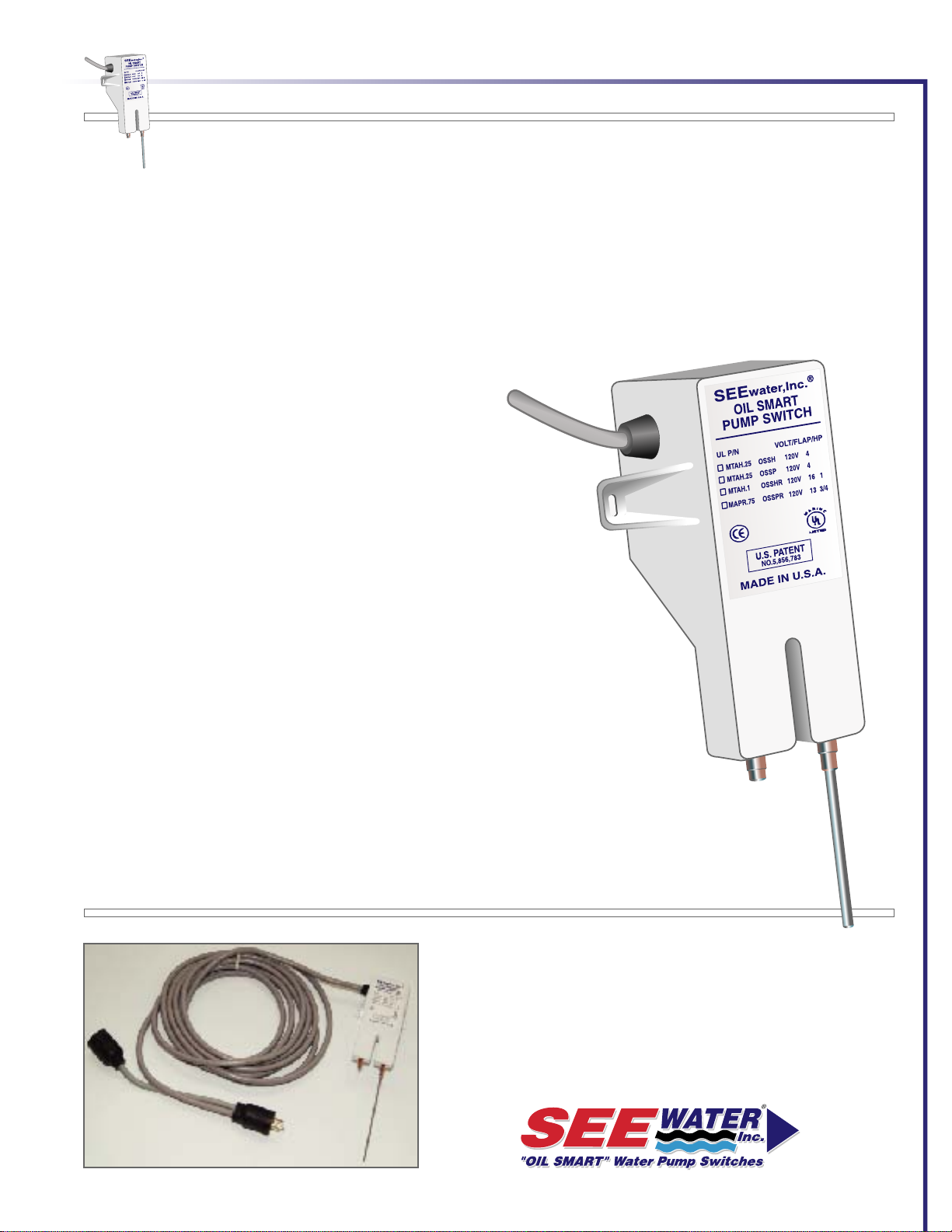
OIL SMART® WATER PUMP SWITCH
Single Phase Oil Smart® NEMA 4X Duplex PanelsOil Smart
The Oil Smart® Pump Controller is a stand-alone pump controller requiring no expensive electrical
panels, will operate any pump up to and including a 1HP. All models include built-in ON and OFF
deferential of 2.5" or 6". An industrial grade switch that differentiates between oil and water, with
any pump application used to control pumps in elevator, utility, marine and industrial sump
applications. Installation will help prevent hydrocarbons from inadvertently being pumped into the
environment and oil will not harm or contaminate this capacitive technology. The Oil Smart®
Switch can be an integral part of the pump assembly or a stand-alone component wired to the
pump or a control valve.
TECHNICAL DATA:
Operating Voltages and Model #:
# Wayne Water Model #15455:
MAPR.75 120VAC 50/60 Hz. 13Amp 3/4 HP PLUG (OSS20PBPR)
Oil Smart® pump controller with 20' cord, bracket and 6" or 2.5" differentialON & OFF SENSORS.
• Dimensions: 2.50" Wide x 6" High x 1.75" Deep plus 2.5" or 6" OFF sensor
• Magnetic Motor Controls UL508 UL Certified File E183129
• Listed Industrial Control Equipment
• Completely Encapsulated & Water Tight
• CE Certified
• A solid-state sensing device that differentiates between water and oil
• Incorporates two level sense points, pump ON, pump OFF.
®
Water Pump Switch Pumps Water Only, Will Not Pump Hydrocarbons
WARRANTY:
• Oil Smart® Pump Switch, SEE Water® Inc. warrants that the See Water Oil Smart Pump Switch
will be free from defects in material and workmanship for a period beginning as of the date of
purchase for two (2) years. Replacement of the switch only at the sole discretion of See Water Inc.
This warranty is valid only when the product is installed in strict compliance with the
manufacturer's installation instructions. SEEwater, Inc. will in no way be responsible for the
reliability of any pump that is connected to or operates with SEEwater, Inc. products. See Water,
Inc. will replace the switch when it is returned to See Water's factory, postage prepaid with proof of
original purchase included.
www.seewaterinc.com
or www.oilsmart.org
951.487.8073 • 888.733.9283
Email: info@seewaterinc.com
121 North Dillon Street • San Jacinto, CA 92583
P.O. Box 1269 • San Jacinto, CA 92581
Fail-Safe Technology since 1995.
Page 2
OIL SMART® WATER PUMP SWITCH
OIL SMART® SWITCH AND PUMP
INSTALLATION:
CAUTION: YOU MUST REMOVE ANY
FLOAT SWITCH THAT IS CURRENTLY IN
USE OR SUPPLIED BY PUMP
MANUFACTURER. IF PUMP HAS
MANUAL/AUTO SET, SWITCH TO
MANUAL.
Installation of the Oil Smart® water pump
switch allows you to comply with State and
Federal regulations while reducing the risk
of adverse publicity, fines and expensive
cleanup costs. The Oil Smart® water
pump switch prevents inadvertently
pumping oil contaminated waste into the
environment, improves the reliability of your
electric system and provides a safe, dry
work environment for your employees.
FUSING:
Follow the pump manufacturer's
instructions. Do not exceed the Oil Smart®
switch amp rating. A portable devise may
not be attached to a permanent
structure.
THE INITIAL INSTALLATION:
should be in a clean environment, clear of
mud and all metallic debris. The switch
should be installed where the water
intrusion will not directly contact or splash
the switch body.
Mud and other conductive materials left on
the body of the switch will hamper its
operation. Effort must be taken to clean the
switch prior to leaving initial installation.
CLEAN STRUCTURE:
requires minimum switch maintenance for a
trouble-free operation. Install the switch so
that on and off sensors clear any metallic
material (earth, mud, concrete and all
metals) by a minimum of 2".
SWITCH MAINTENANCE:
The white plastic case must be clean of any
conductive materials (dirt, soap or rust).
Clean with alcohol.
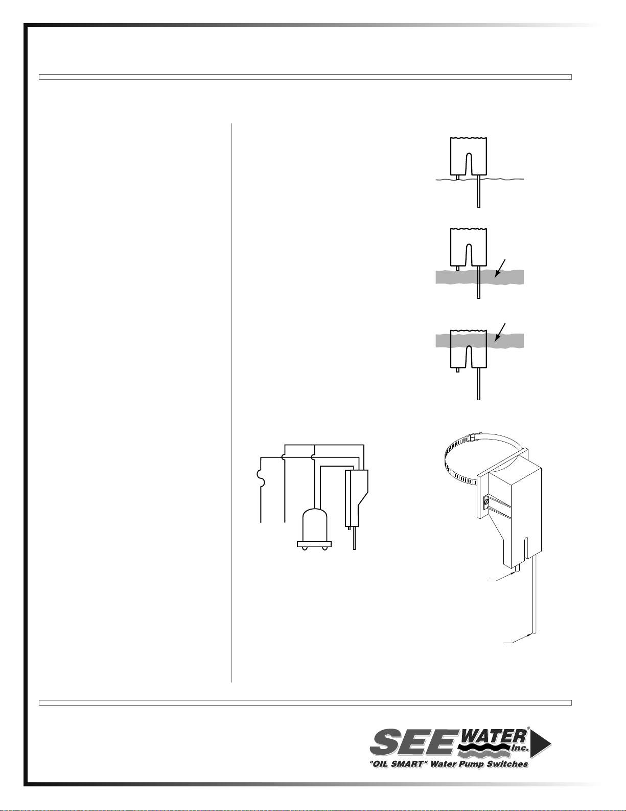
OPERATION:
Normal Condition (Water Only)
The short sensor probe turns the pump "on"
and the long sensor probe turns the pump
"off". When the short sensor is in contact
with water, the pump will continue to cycle
"on and off" until the short sensor detects
oil.
Oil Present Condition
The pump will not cycle if oil is in contact
with the short sensor.
High Water (Oil Present Condition)
If additional water enters the basin, it will
cause the oil layer to rise above the short
sensor, resulting in the pump cycling.
WIRING DIAGRAM
WHITE
BLACK
FUSE
AC
VOLTAGE
SOURCE
PUMP
BROWN
OIL
SMART®
SWITCH
WATER
OIL
LAYER
WATER
OIL
LAYER
WATER
"ON"
"OFF"
www.seewaterinc.com or www.oilsmart.org
951.487.8073 • 888.733.9283 • Email: info@seewaterinc.com
121 North Dillon Street • San Jacinto, CA 92583
Printed in U.S.A.
P.O. Box 1269 • San Jacinto, CA 92581
Fail-Safe Technology since 1995.
Page 3

Oil Smart® Switch
Trouble Free Operation
1. Plastic Switch case must be kept clean. Free of: rust, mud, soap, etc. If switch
is submerged in water during initial installation, switch must be cleaned.
2. Clean with Alcohol or an oil base product: kerosene, solvent.
3. Pumps with an attached float switch, Float switch must be removed or
secured in manual operation before attaching the Oil Smart® switch.
4. Mount switch in secure manner to: pump PVC pipe, do not mount to metallic
material.
5. Mount in sump clear of water inlet keeping switch case clean & dry as possible.
6. Keep bottom of long sensor at least two inches above pump inlet (Impellor).
7. Keep sensors one to two inches (1 to 2”) clear of any metallic material.
8. Switch will not function with incorrect polarity (Polarity Sensitive).
9. Supply voltage: 115AC and 240AC For European model.
10. Pump turns on when water covers long and short rod.
11. Test switch: to simulate water, place thumb and finger on sensor rods let go of
short rod and firmly slide finger down long rod, switch will turn off when finger
is clear of long rod.
Page 4

Blue Angel High Water / Oil Alarm
Model ODS10 - 1/3 HP SSBCSM33
Model ODS20 - 1/2 HP SSBCSM50
Blue Angel High Water / Oil Alarm - High Head
Model ODS30 - 1/2 HP BALE521A (230 Volts)
or BALE511A (115 Volts)
High Water /
Alarm Contactor
SEE WATER
Pump Switch
12½”
3½”
On
SEE WATER INC
Water Oil
Oil Smart® Alarm System
SILENCE TEST
8½”
SEE WATER INC
Water Oil
Oil Smart® Alarm System
SILENCE TEST
1½”
4¾”
®
2½”
Alarm Panel Cord Length:
Alarm Panel is Hard-Wired
To Alarm Contactor.
Standard Length = 20 Feet
Longer Lengths Available.
Call Blue Angel Pumps Customer Service
For Assistance When Ordering:
1-888-636-6628
On
Operational
Minimum
4” Depth
Basin Floor
6”
Area
Off
9”
ODS10 and ODS20
Min. Basin Depth = 20”
Min. Basin Width = 14”
Off
11 ½”
11 ⅞”
Minimum
6½” Depth
9⅞”
ODS30
Min. Basin Depth = 22½”
Min. Basin Width = 14”
10/09
 Loading...