

Blue Angel Pumps BEWP10 User Manual [en, es]
The Professional’s Line
Installation Instructions BEWP10
Please read and save these instructions. Read carefully before attempting to assemble,
install, operate or maintain the product described. Protect yourself and others by
observing all safety information. Failure to comply with instructions could result in
personal injury and/or property damage! Retain instructions for future reference.
Water Powered Back-up
Sump Pump System
Description
The BEWP10 is a water powered
back-up sump pump. It does not
replace a regular pump. This pump
is designed for use with municipal
water systems and is inteded to be
used as an emergency backup to your
existing sump pump.
Unpacking
Inspect this unit before it is used.
Occasionally, products are damaged
during shipment. If the pump or
components are damaged, return
the unit to the place of purchase for
replacement. Failure to do so could
result in serious injury or death.
Safety Guidelines
This manual contains information
that is very important to know and
understand. This information is
provided for SAFETY and to PREVENT
EQUIPMENT PROBLEMS. To help
recognize this information, observe
the following symbols.
Danger
an imminently hazardous situation
which, if not avoided, will result in
death or serious injury.
Warning
a potentially hazardous situation which,
if not avoided, could result in death or
serious injury.
Caution
a potentially hazardous situation which,
if not avoided, may result in minor or
moderate injury.
Notice
important information, that if not
followed, may cause damage to
equipment.
indicates
indicates
indicates
indicates
General Safety
Information
Do not use to pump fl ammable
or explosive fl uids such as
gasoline, fuel oil, kerosene,
etc. Do not use in a fl ammable and/or
explosive atmosphere. Pump should only
be used to pump clear water. Fatal injury
and/or property damage could result.
REMINDER: Keep your dated proof of purchase for warranty purposes! Attach it to this manual or fi le it for safe keeping.
© 2007 Blue Angel™ Pumps
If the basement has water
or moisture on the fl oor, do
not walk on wet area until all
power is turned off. If the shutoff box
is in the basement, call an electrician.
Remove pump and either repair or
replace. Failure to follow this warning
could result in fatal electrical shock.
A check
must be used on the primary sump
pump discharge.
This
must only be used to pump clear water.
This pump is not designed to handle
effl uent, salt water, brine, laundry
discharge or any other application
which may contain caustic chemicals
and/or foreign materials. Pump damage
may occur if used in these applications
and will void warranty.
valve
pump
Installation
Installation of this unit may take
several hours. Before disabling your
main pump, have ready an appropriate
means of evacuating the sump.
1. Turn power to main pump off.
2. Pump must be installed using 1¼”
or 1½” rigid PVC pipe. Do not use
fl exible drain hose.
Pump Installation
The BEWP10 can be installed with
a separate dedicated discharge line
(Figure 1, Method 1) or tied into the
existing sump pump line (Figure 2,
Method 2).
Unplug
existing AC pump. Failure to follow this
warning could result in fatal electrical
shock.
3. Verify that the existing AC pump
is in good working order. If the
AC pump is questionable, it is
recommended that the unit be
replaced.
4. Remove any silt or accumulated
debris from the sump pit and
surrounding area.
5. Locate the BEWP10 in an ideal
position in the sump pit. The
ideal position is approximately
2” from the bottom of the sump
pit and located so that it does
not interfere with any part of the
existing sump pump.
For parts, product & service information
www.blueangelpumps.com
visit
the
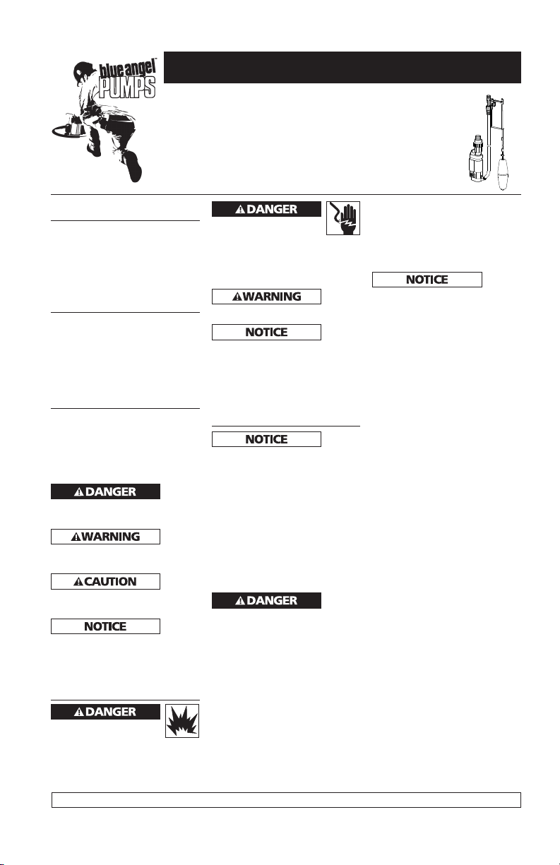
6. Method 1 Installation:
(Figure 1) Cut and dry-fi t rigid
PVC pipe to the discharge of the
water powered back-up pump.
Cement all fi ttings and discharge
pipe after all pipe has been cut
and dry-fi t together.
The
line installation will vary depending on
individual circumstances. Using sound
plumbing practices, route the discharge
pipe to an exterior wall by the shortest
path. Keep turns to a minimum because
they reduce the fl ow output of the pump.
The pipe that exits the building structure
should be sealed and sloped downward
so the water will not freeze in the pipe.
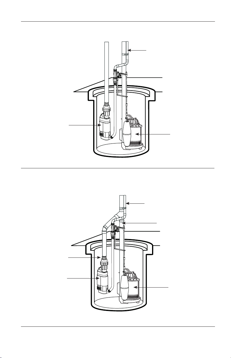
Method 2 Installation:
(Figure 2) Cut the existing main
pump discharge line and cement
a “T” or “Y” fi tting. Measure,
cut and dry-fi t the pipe required
to connect the BEWP10 to the
installed “T” or “Y” fi tting.
Cement all fi ttings and pipe.
7. Shut off the municipal water
supply. Install a rigid water
supply line to the sump area.
Include a shut-off valve in the
supply line. Flush the supply line
of all debris before installing the
automatic valve.
8. Connect the automatic valve
assembly with brass vacuum
breaker to the supply line. Is
should be located about 6” above
the basement fl oor or sump pit
cover. The supply line needs to be
supported.
9. Attach the hose coupling and
washer to the brass vacuum
breaker of the automatic valve
assembly.
10. Attach the “L” bracket to the
automatic control valve using the
two screws supplied.
11. Install the fl oat rod by threading
the two parts together. Using
the large coupler, secure the rod
connection by threading the top
screw to the top part and the
bottom screw to the bottom part.
12. Install a small coupler and the
fl oat to the fl oat rod by inserting
the fl oat rod through the center
of the fl oat. Insert a small coupler
about ½” above the bottom of
the fl oat rod and tighten the
fastener. Tighten the fi rst small
coupler installed.
discharge
353300-002 7/07

Installation Instructions
Installation
(Continued)
13. The fl oat should be set so that
the primary pump starts before
the BEWP10. Insert the fl oat rod
through the “L” bracket hole.
Install a rubber grommet onto the
fl oat rod, then insert the fl oat rod
through the automatic control
valve arm and then install the
second rubber grommet on the
top of the fl oat rod.
14. If necessary, adjust the length of
the connecting hose and attach
to the BEWP10 pump with the
supplied hose clamp.
15. Turn on the water supply and
check the installation for joint
leaks and proper operation.
Simulate water activating the
water powered backup system
by raising the fl oat to trip the
automatic control valve arm.
Hold the fl oat in the up position
while checking the system for
leaks. Lower the fl oat to turn off
the system and fi x any leaks in
the water supply line. Retest if
necessary.
16. Fill the pit with water until the
fl oat trips the automatic control
valve arm. The system will lower
the water level in the pit to the
shut off point of the BEWP10.
Verify this on/off level of the
BEWP10 is higher than the on
level of the main sump pump.
17. Reconnect power to the main
sump pump. The water level in
the pit should lower to the off
point of the main sump pump.
Test the system again to verify
that the main sump pump and
the BEWP10 work together.
Troubleshooting Chart
Symptom Possible Cause(s) Corrective Action
No Water is pumped
out
Pump does not pump
water to full capacity
Pump does not
shut off
1. Water supply valve closed
2. Automatic valve closed
3. Float does not rise with water
level
4. Suction or ejector clogged
5. Water level below suction in
sump
6. Improper function or missing
check valve in primary pump
discharge
7. Discharge line clogged
8. Pumping height more than
15 ft.
9. Water pressure less than 40 psi
1. Water supply partially opened
2. Automatic valve partially
opened
3. Suction or ejector partially
clogged
4. Leaky primary pump check
valve
5. Discharge line partially clogged
1. Automatic valve does not shut
off
2. Float is obstructed
1. Open supply valve
2. Check manually the valve operation
3. Check for obstruction of fl oat action
4. Clean pump inlet
5. Adjust the fl oat rod to shut off pump prior to low water
level
6. Install check valve in primary pump discharge
7. Check all discharge lines
8. Reduce pumping elevation to less than 15 ft
9. Run a 3/4” direct line from water supply to reduce friction
loss in pipe
1. Open supply valve
2. Check the valve operation
3. Clean pump inlet
4. Replace check valve in primary pump discharge
5. Check all discharge pipes
1. Check the valve operation
2. Check for obstruction or adjust rubber grommet to proper
off and on position
Operation
Always disconnect the power
source before attempting to
install, service, relocate or
maintain the pump. Never touch sump
pump, pump motor, water or discharge
piping when pump is connected to
electrical power. Never handle a pump
or pump motor with wet hands or when
standing on wet or damp surface or in
water. Fatal electrical shock could occur.
Risk of electrical shock! Use a
GFCI receptacle to reduce the
risk of fatal electrical shock.
Cutting the cord or plug will void
the warranty and make the pump
inoperable.
www.blueangelpumps.com
2
BEWP10
Typical Installation with Submersible Pump with a Separate Discharge Pipe
Water Supply
Water-Powered
Backup Sump
Main Sump
Pump
Figure 1
Typcial Installation with Submersible Pump
Figure 2
Check valve
Water-Powered
Backup Sump
Water Supply
D
Check valve
Main Sump
Pump
www.blueangelpumps.com
3
 Loading...