

Page 1
Specifications
Power supply
requirements . . . . . . . . . .120V, 60 Hz,
1 phase
Motor duty . . . . . . . . . . .Intermittent
Liquid temperature
range . . . . . . . . . . . . . . . .40°F to 125°F
Max. operating
position . . . . . . . . . . . . . .45ofrom
vertical
Dimensions . . . . . . . . . . .10” X 5” X
4-3/4”
Discharge . . . . . . . . . . . . .3/8"ID
Power cord . . . . . . . . . . .6'
3 conductor
with ground
Reservoir . . . . . . . . . . . . .2 quart
plastic
Description
A condensate unit removes
condensation from air conditioning
and high efficiency furnaces. The
compact design of the unit consists of a
3/8” ID discharge and 6 ft. long power
cord. The unit also contains a safety
switch to automatically shut off pump
in the event of a failure.
Unpacking
Inspect this unit before it is installed.
Occasionally, products are damaged
during shipment. If the pump or
components are damaged, return the
unit to the place of purchase for
replacement. Failure to do so could
result in serious injury or death.
This pump is not
designed to handle
salt water, brine, laundry discharge, or
any other application which may contain
caustic chemicals and/or foreign
materials. Pump damage could occur if
used in these applications and will void
warranty. Use for clear water application
only.
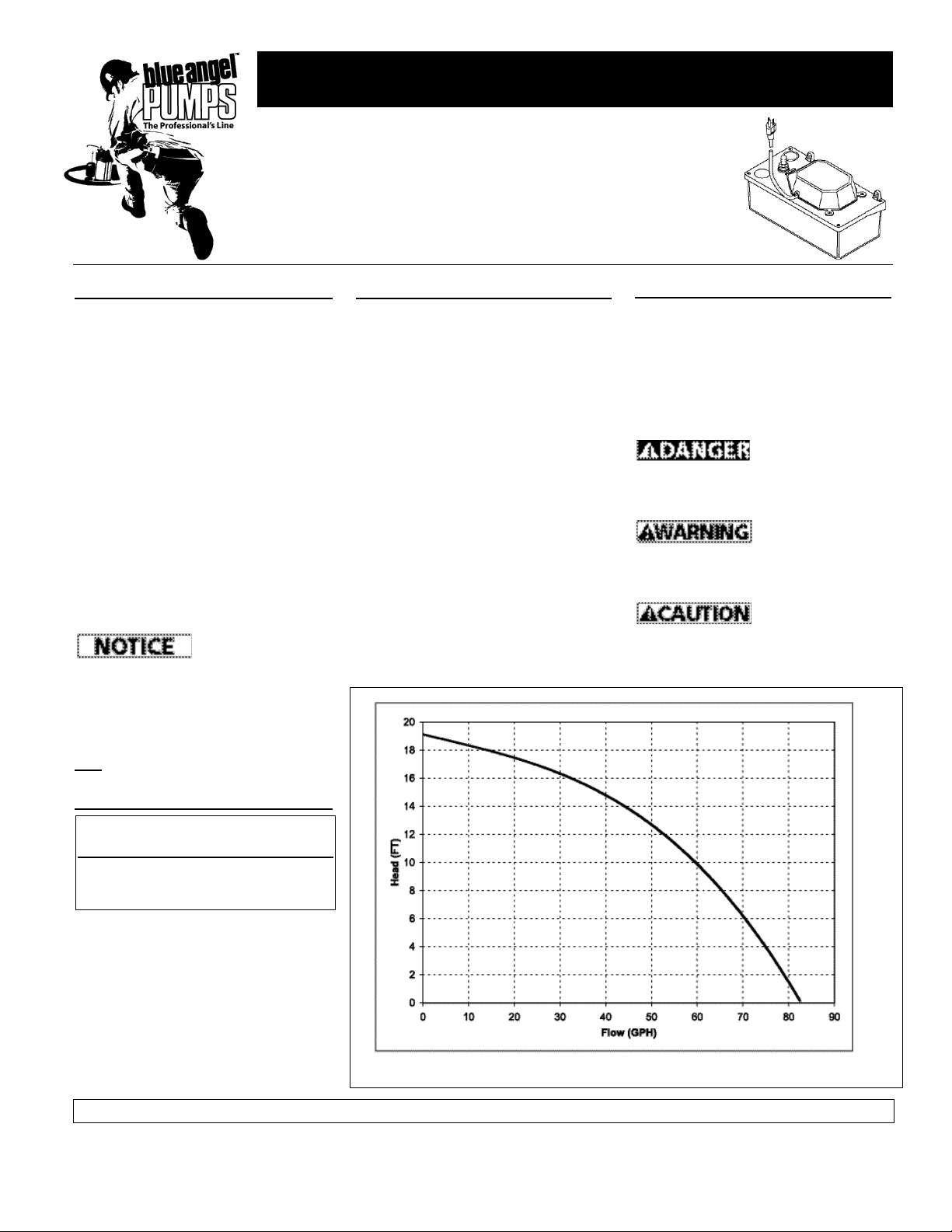
Performance
Operating Instructions and Parts Manual Model BCP20ULS
370103-002 1/07
Safety Guidelines
This manual contains information that
is very important to know and
understand. This information is
provided for SAFETY and to PREVENT
EQUIPMENT PROBLEMS. To help
recognize this information, observe the
following symbols.
Danger indicates
an imminently
hazardous situation which, if not
avoided, will result in death or serious
injury.
Warning indicates
a potentially
hazardous situation which, if not
avoided, could result in death or serious
injury.
Caution indicates a
potentially
hazardous situation which, if not
avoided, MAY result in minor or
moderate injury.
© 2007 Blue Angel ™ Pumps
Condensate Unit
GALLONS PER HOUR
AT TOTAL HEAD IN FEET
Head (ft) 2 6 8 10 19
Flow (GPH) 78 72 66 59 0
For parts, product & service information
visit www.blueangelpumps.com
REMINDER: Keep your dated proof of purchase for warranty purposes! Attach it to this manual or file it for safekeeping.
Figure 1 - Performance Chart
Please read and save these instructions. Read carefully before attempting to assemble,
install, operate or maintain the product described. Protect yourself and others by
observing all safety information. Failure to comply with instructions could result in
personal injury and/or property damage! Retain instructions for future reference.
Page 2
be shut-off or obstructed.
9. Personal Safety:
a. Wear safety glasses at all times
when working with pumps.
b. Keep work area clean,
uncluttered and properly lighted;
replace all unused tools and
equipment.
c. Keep visitors a safe distance from
the work area. Make workshop
child-proof with pad locks, master
switch es, and by re mov ing starter
keys.
10. When wiring an elec tri cal ly driven
pump such as this, fol low all electrical
and safety codes, as well as the most
recent National Electrical Code (NEC)
and the Oc cu pa tion al Safety and
Health Act (OSHA).
Risk of electric shock! Never
connect the green (or green
and yellow) wire to a live
terminal!
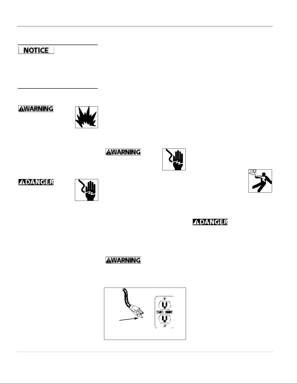
11. This equipment is only for use on
120 volt (single-phase) and is
equipped with an ap proved 3-con duc tor cord and 3-prong,
grounding-type plug as shown in
Fig ure 2.
To reduce the risk of electric shock, the
motor must be securely and adequately
grounded. This can be ac com plished by
inserting plug directly into a properly
installed and grounded 3-prong,
grounding-type re cep ta cle (as shown in
Figure 2).
Risk of electrical
shock! This pump is
supplied with a grounding conductor
and grounding type attachment plug.
Use a grounded receptacle to reduce
the risk of fatal electric shock.
Safety Guidelines
(Continued)
Notice indicates
indicates important
information, that if not followed, may
cause damage to equipment.
General Safety
Information
1. Know the pump application,
limitations, and po ten tial hazards.
Do not
use to
pump flammable or explosive
fluids such as gasoline, fuel
oil, kerosene, etc. Do not use
in flammable and/or explosive
atmospheres. Use pump only with liquids
compatible with pump component
materials. Failure to follow this warning
can result in personal injury and/or
property damage.
2. Make certain that the power supply
conforms to the requirements of
the unit.
Disconnect power before
servicing. If the power dis con nect is out of sight, lock
in the open po si tion and tag it to
prevent unexpected application of
power. Failure to do so could result in
fatal electrical shock!
3. Release all pressure within the
system before ser vic ing any
component.
4. Drain all liquids from the system
before servicing.
5. Secure the discharge line before
starting the pump. An unsecured
discharge line will whip, possibly
causing personal injury and/or
property damage.
6. Check hoses for weak and worn
condition before each use, making
certain that all connections are
secure.
7. Periodically inspect the pump and
system com po nents. Perform
routine maintenance as required
(See Maintenance Section).
8. Provide a means of pressure relief
for pumps whose discharge line can
Operating Instructions and Parts Manual
Never cut off the round grounding
prong. Cutting the cord or prong
will void the warranty and make
the pump inoperable.
Where a 2-prong wall receptacle is
encountered, it must be replaced with
a properly grounded 3-prong re cep ta cle installed in accordance with the
NEC and local codes and ordinances.
12. All wiring should be performed by a
qualified elec tri cian.
13. It is strongly recommended that this
unit is plugged into a Ground Fault
Circuit Interrupter (GFCI). Con sult a
local electrician for installation and
availability.
14. Protect electrical cord from sharp
objects, hot sur fac es, oil, and
chemicals. Avoid kinking the cord.
Re place or repair damaged or worn
cords im me di ate ly. Use wire of
adequate size to minimize voltage
drop at the motor.
15. Do not handle a pump
or pump motor with
wet hands or when
standing on a wet or
damp surface, or in
water.
16. Do not use an extension cord.
Do not
walk on wet area
until all power has been turned off. If
the shut-off box is in basement, call
the electric company to shut-off service
to the house, or call the local fire
department for instructions. Remove
pump and repair or replace. Failure to
follow this warning can result in fatal
electrical shock.
Grounding
Blade
Figure 2 - Grounding
2
www.blueangelpumps.com
Page 3
3
Model BCP20ULS
www.blueangelpumps.com
Installation
In any installation
where property
damage and/or personal injury might
result from an inoperative or leaking
pump due to power outages, discharge
line blockage or any other reason, use
a backup system(s).
STEP 1: INSTALLATION OF PIPE
A. Insert the discharge pipe or pipe
nipple into the 3/8” ID plastic tube.
Before removing
pump from its
mounting position for service, always
disconnect electrical power to pump
and control switch. For any work on
pump or switch, ALWAYS unplug the
power cord. Do not just turn off circuit
break er or unscrew fuse.
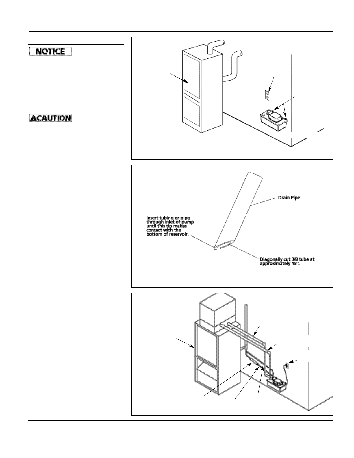
STEP 2: MOUNTING
CONDENSATE UNIT
A. Position the pump below the
evaporator drain and/or furnace
drain.
B. The pump can be installed to the
wall or side of the appliance using
the two mounting brackets. Refer to
Figure 3.
STEP 3: INSTALLATION OF
CONDENSATE DRAIN LINES
A. To prevent pipe blockage in the
reservoir, modify the end of pipe or
tubing as illustrated in Figure 4.
B. Plumb flexible tube or pipe from the
condensate drain, and from the
furnace drain (if applicable), to the
inlet holes on the pump. Refer to
Figure 5.
STEP 4: INSTALLATION OF
DISCHARGE LINE
NOTE: Use 3/8” I.D. (max.) flexible
tubing. A hose clamp is recommended
(not provided).
A. Extend discharge pipe from barbed
check valve to the highest point
possible. Refer to Figure 6.
B. From this point, direct the
discharge line to the location of the
drainage source. Maintain a
continuous downward slope.
NOTE: Construct an inverted “U” (see
Figure 6) at the highest point of
discharge line if a continuous
downward slope is not possible.
Exercise care not to kink or “pinch off”
the flow of condensate liquid.
Figure 3 - Mounting location
Figure 4 - Modification of pipe end to prevent blockage
Figure 5 - Plumbing pipe from drain to inlet holes on pump
GFCI Outlet
Mounting
brackets
6 1/2” above floor
High efficiency
gas furnace
Main Drain from Coil
Overflow Drain from
Coil When Required
GFCI
Outlet
Overflow Drain
from Furnace
Condensate Neutralizer
Cartridge (If Required)
Main Drain
from Furnace
High efficiency
gas furnace
Page 4

Operating Instructions and Parts Manual
4
www.blueangelpumps.com
Installation
(Continued)
STEP 5: INSTALLATION OF
SAFETY SWITCH (IF APPLICABLE)
Connect power cord
to a constant
voltage source. Do not connect to a fan
or other device that may run
intermittently.
A. The pump can be wired directly to
the appliance thermostat to shut
the pump and appliance down in
the event of pump failure. Refer to
Figure 7 for typical wiring diagram.
NOTE: The alarm can be wired in the
safety switch at the normally open
(“NO”) contact.
TIPS FOR EASY INSTALLATION
1. After reading instructions, check to
make sure installation does not
exceed a maximum of 15 feet of
vertical lift.
2. Make sure pump is level. No part of
the pump base should be more
than 1/8” off of level plane.
3. Use soapy water on unit when
performing cleaning maintenance.
(Refer to Maintenance guidelines.)
4. For optimum performance, drain
and discharge lines should have a
continuous downward slope. Test
operation of pump to make sure
lines have enough downward slope
for efficient operation.
5. Avoid overtightening of check valve
after cleaning. (Refer to
Maintenance gudelines.)
6. Use constant voltage power source.
Do not plug into a device that runs
intermittently.
7. Locate model number and date
code on pump and take note of
them.
8. To assure proper performance, the
highest point of discharge line
should be higher than 5’ off the
floor.
9. Clean any debris in the pump
reservoir if necessary.
10. Do not handle the pump until you
have disconnected it from the
power source. Follow all guidelines
Figure 6 - Installation of discharge line
Figure 7 - Typical wiring diagram for pumps provided with safety switch
NOTE: The alarm can be wired into the safety
switch at the normally open (“NO”) contact.
for electrical safety discussed in
General Safety.
11. Do not use a pump discharge pipe
smaller than the pump discharge
size.
12. After installation, test pump to
make sure that system is working
properly.
13. Make sure that installation
conforms to all local and national
codes.
14. Local codes may require the use of a
condensate neutralizer when using
this pump.
Maintenance
Make certain that
the pump is
unplugged before attempting to
service or remove any component. This
pump is assembled in the factory using
special equipment; therefore only
authorized service dealers or qualified
electricians should attempt to repair
this unit. Improper repair can cause an
electrical shock hazard.
CLEANING RESERVOIR AND
IMPELLER
1. Unscrew two screws through
mounting brackets, and remove
pump from wall, if mounted.
15 Ft.
Max
Inverted “U”
To Main Drain
Hose clamp
(recommended, not included)
GFCI
Outlet
Do not kink or pinch
3/8” ID Tubing
Typical Thermostat
Typical Thermostat Connections of Appliance
Overflow
Safety Switch
Page 5

5
Model BCP20ULS
www.blueangelpumps.com
Maintenance
(Continued)
2. Remove reservoir from deck by
unscrewing the four screws located
at the corners of the reservoir cover.
3. Remove the impeller cover by
unscrewing the five screws on the
underside of the motor. Pull out the
impeller shaft assembly.
4. Use a damp cloth to wipe off the
gasket and the motor assembly.
5. Reassemble impeller to motor. Then
reassemble reservoir to reservoir
cover.
CLEANING CHECK VALVE
1. Disconnect discharge line from
check valve – see Figure 8.
2. Remove check valve with 9/16”
wrench.
3. Visually check for obstructions or
damage.
4. If check valve is not damaged,
replace valve by hand-tightening.
Then tighten 1/2” turn with 9/16”
wrench.
Do not overtighten.
Damage to O-ring
seal may occur.
Notes
check valve
Figure 8 - Check valve
Page 6

Operating Instructions and Parts Manual
6
www.blueangelpumps.com
Notes
Page 7

7
Model BCP20ULS
www.blueangelpumps.com
Troubleshooting Chart
Pump may start unexpectedly. Disconnect power supply before ser vic ing.
Symptom Possible Cause(s) Corrective Action
Pump fails to run
Pump emits loud noises
when operating
Pump operates but
there is no flow of
liquid
Liquid drains back into
pump from discharge
line
Liquid leaks from
around check valve
1. Pump not plugged in
2. Low voltage, blown fuse, open
circuit
3. Reservoir is absent of
condensate
4. Drain/discharge lines blocked
Foreign material in reservoir
1. Float is sticking
2. Discharge height greater than
15 feet
3. Obstruction in discharge tube
4. Blockage in check valve
5. Damaged check valve
1. Damaged check valve
2. Blockage in check valve
3. Discharge line is 5’ or less
1. Check valve fastened too tight
or too loose
2. Damage to O-ring
1. Plug in.
2. Have a certified electrician check fuse circuit.
3. Make sure that there is adequate condensate level in
reservoir. Check drain lines and/or discharge line for
obstructions.
4. Check drain lines and/or discharge line for obstructions.
Refer to Maintenance section for cleaning instructions.
1. Refer to Maintenance section for cleaning instructions.
2. Measure from bottom of pump to highest point. Rework
discharge if height is greater than 15’. Refer to Installation
Step 4 for instructions.
3. Check discharge line for blockage. Remove debris.
4. Refer to Maintenance section for cleaning instructions.
5. Contact Blue Angel Pumps.
1. Contact Blue Angel Pumps.
2. Refer to Maintenance section for cleaning instructions.
3. Condensate liquid may drain out of line into reservoir due
to discharge height. This is normal. No action is necessary.
1. Check valve should be hand-tightened, then tightened an
additional 1/2 turn with a 9/16” wrench.
2. Replace with a 1/2” ID x 11/16” OD x 3/32” thick O-ring or
contact Blue Angel Technical Service at 1-800-237-0987,
Before servicing a pump, always shut off the main power breaker and then unplug the pump.
Make sure you are not standing in water. Make sure you are wearing insulated, protectivesoled shoes. Under flooded conditions, check your local electric company or a qualified licensed electrician for
disconnecting electrical service prior to pump removal. If the above checklist does not solve the problem, contact
Blue Angel Technical Service at 1-800-237-0987.
Page 8

Limited Warranty
For one year from the date of purchase, Blue Angel will repair or re place, at its option, for the original purchaser any part
or parts of its Sump Pumps or Water Pumps (“Product”) found upon examination by Blue Angel to be defective in
materials or work man ship. Please call Blue Angel (800-237-0987) for instructions or see your dealer. Be pre pared to provide
the model number and the serial number when exercising this warranty. All transportation charges on Products or parts
submitted for repair or replacement must be paid by purchaser.
This Limited Warranty does not cover Products which have been damaged as a result of accident, abuse, misuse, neglect,
improper installation, improper maintenance, or failure to operate in accordance with Blue Angel’s written instructions.
THERE IS NO OTHER EXPRESS WARRANTY. IMPLIED WARRANTIES, IN CLUD ING THOSE OF MER CHANT ABIL I TY AND
FITNESS FOR A PARTICULAR PUR POSE, ARE LIMITED TO ONE YEAR FROM THE DATE OF PURCHASE. THIS IS THE
EXCLUSIVE REM E DY AND ANY LIABILITY FOR ANY AND ALL INDIRECT OR CONSEQUENTIAL DAM AG ES OR
EXPENSES WHATSOEVER IS EXCLUDED.
Some states do not allow limitations on how long an implied warranty lasts, or do not allow the exclusions or limitations of
incidental or consequential damages, so the above lim i ta tions might not apply to you. This limited war ran ty gives you
specific legal rights, and you may also have other legal rights which vary from state to state.
In no event, whether as a result of breach of contract warranty, tort (in clud ing negligence) or otherwise, shall Blue Angel
or its suppliers be liable for any special, consequential, incidental or penal damages including, but not limited to loss of
profit or revenues, loss of use of the products or any associated equipment, damage to associated equip ment, cost of
capital, cost of substitute products, facilities, services or replacement power, downtime costs, or claims of buyer’s cus tom ers
for such damages.
You MUST retain your purchase receipt along with this form. In the event you need to exercise a warranty claim, you
MUST send a copy of the purchase receipt along with the material or correspondence. Please call Blue Angel (800-237-
0987) for return authorization and instructions.
DO NOT MAIL THIS FORM TO BLUE ANGEL. Use this form only to maintain your records.
MODEL NO._______________ SERIAL NO.__________________________ INSTALLATION DATE_____________
ATTACH YOUR RECEIPT HERE
8
Operating Instructions and Parts Manual
www.blueangelpumps.com
 Loading...