

Page 1
Operating Instructions 2 HP Grinder Pumps
Please read and save these instructions. Read carefully before attempting to assemble, install,
operate or maintain the product described. Protect yourself and others by observing all safety
information. Failure to comply with instructions could result in personal injury and/or property
damage! Retain instructions for future reference.
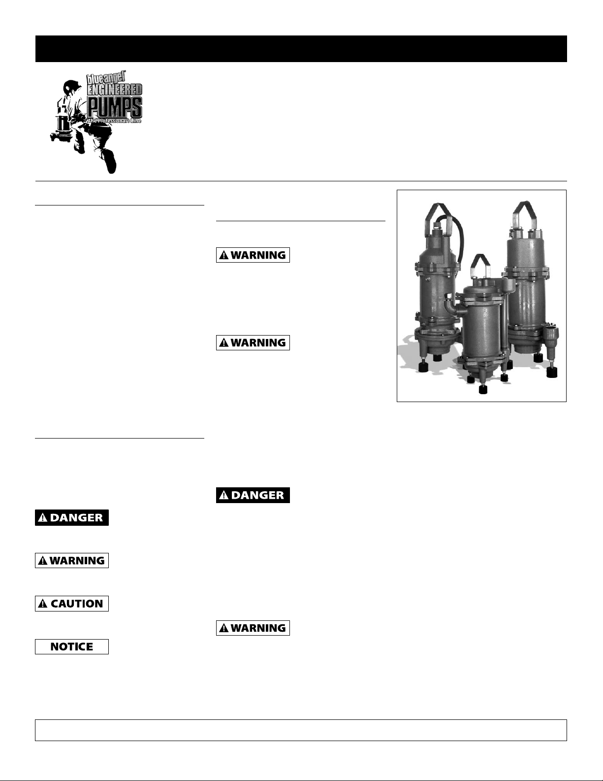
2 HP Grinder Pump
Description
The 2 HP Grinder is a submersible
wastewater pump designed specifically
for pumping domestic sewage. One
pump can handle the sewage for a
maximum of 2 homes. These pumps are
not to be used for pumping commercial
or industrial sewage from factories,
schools, motels, apartments, etc. This
pump is not for use in hazardous
locations!
UNPACKING AND INSPECTION
Inspect this unit before it is used.
Occasionally, products are damaged
during shipment. If the pump or
components are damaged, return
the unit to the place of purchase for
replacement. Failure to do so could
result in serious injury or death.
Safety Guidelines
This manual contains information that is
very important to know and understand.
This information is provided for SAFETY
and to PREVENT EQUIPMENT PROBLEMS.
To help recognize this information,
observe the following symbols.
Danger indicates an
imminently
hazardous situation which, if not avoided,
will result in death or serious injury.
Warning indicates a
potentially
hazardous situation which, if not avoided,
could result in death or serious injury.
Caution indicates a
potentially hazardous
situation which, if not avoided, may result
in minor or moderate injury.
Notice indicates
important
information, that if not followed, may
cause damage to equipment.
NOTE: Information that requires special
attention.
General Safety
Information
CALIFORNIA PROPOSITION 65
This product or its
power cord may
contain chemicals known to the State
of California to cause cancer and birth
defects or other reproductive harm.
Wash hands after handling.
1. Know the pump application,
limitations and potential hazards.
Do not use to
pump flammable or
explosive fluids such as gasoline, fuel oil,
kerosene, etc. Do not use in flammable
and/or explosive atmospheres. Use to
pump only with liquids compatible with
pump components materials. Failure
to follow this warning can result in
personal injury and/or property damage.
2. Only qualified personnel should
install, operate and repair this pump.
3. Make certain that the power source
conforms to the requirement of the
equipment.
Disconnect power
before servicing. If
the power disconnect is out of sight,
lock in the open position and tag it
to prevent unexpected application of
power. Failure to do so could result in
fatal electrical shock!
4. Release all pressure within the
system before servicing any
component.
5. Drain all liquids from the system
before servicing.
This pump contains
dielectric motor oil
for motor heat transfer. Care should be
taken when disposing of this oil. Do
not use this pump in ponds or fountains
because the motor oil can be harmful to
aquatic life.
6. Check your local codes before installing.
You must comply with local rules.
Figure 1
7. Vent any sewage or septic tank
according to local codes.
8. Always keep the shut-off valve
completely open when the system
is in operation (unless advised
otherwise by the proper authorities).
Before removing the pump form the
basin, be sure to close the shut-off
valve. (This prevents back-flow from
the pressure sewer.)
9. Keep the control panel locked or
confined to prevent unauthorized
access to it.
10. Secure the discharge line before
starting the pump. An unsecured
discharge line will whip, possibly
causing personal injury and/or
property damage.
11. Periodically inspect the pump
and system components. Perform
maintenance as required. If the
pump is idle for long periods
of time, add water to the basin
occasionally to start the pump.
REMINDER: Keep your dated proof of purchase for warranty purposes! Attach it to this manual or file it for safekeeping.
© 2009 Blue Angel™ Pumps For parts, product & service information
visit www.waynewatersystems.com
332304-002 10/09
Page 2

Operating Instructions
2 HP Grinder Pumps
12. Provide a means of pressure relief
for pumps whose discharge line can
be shutoff or obstructed.
13. Do not install the pump in any
location classified as hazardous by
National Electric Code, ANSI/NFPA
70-1984.
14. Secure the pump in its operating
position so it cannot tip over, fall or
slide. Install this pump in the vertical
position only.
15. Make sure lifting handles are securely
fastened each time before lifting. Do
not operate pump without safety
devices in place. Always replace safety
devices that have been removed
during service or repair. DO NOT LIFT
PUMP BY POWER CORD.
16. Do not run the pump dry. Dry
running can overheat the pump and
will void the warranty.
17. Personal Safety:
a. Wear safety glasses at all times
when working with pumps.
This pump is designed to
handle materials that could
cause illness or disease through
direct exposure. Wear and
use protective clothing when
working on the pump or piping.
b. Do not wear loose clothing that
may become entangled in the
impeller or other moving parts.
c. Keep clear of suction and
discharge openings. DO NOT
insert fingers in the pump with
power connected.
d. Keep work are clean,
uncluttered and properly
lighted: replace all unused tools
and equipment.
e. Keep visitors a safe distance
from the work area. Make
workshop childproof with
padlocks, master switches, and
by removing starter keys.
18. A qualified electrician should
perform all wiring of this pump.
When wiring an electrically driven
pump such as this, follow all
electrical and safety codes, as well
as the most recent National Electric
Code (NEC) and the Occupational
Safety and Health Act (OSHA).
Risk of Electric Shock!
Never connect the
green (or green and yellow) wire to a
live terminal!
This unit is not
designed for
application involving salt water or brine.
Use with salt water or brine will void
warranty.
Installation
This pump may be installed on a guiderail lift-out system for ease of inspection
and service. Guide-rails allow removal
of the pump without disturbing the
piping and eliminates the need to enter
the basin. If installed with a guide-rail
system, place the pump opposite the
influent opening to prevent stagnant
areas where solids can settle.
Install the pump on a hard, level surface.
Never place the pump directly on earth,
clay or gravel surfaces. The basin must be
at least 18” in diameter and 30” deep.
The discharge pipe must not be smaller
than the pump discharge.
The motor is provided with a thermal
overload switch (Single Phase Pump
Motors Only). If the motor overloads
or overheats for any reason, the switch
opens, stopping the motor. As soon as the
motor cools to normal temperature, the
switch automatically closes and restarts the
motor. On 3-Phase pumps, the installer
must provide the Motor Protection. In
accordance with the National Electric
Code, all 3-phase pumps must be
installed with magnetic starters having
3 leg overload protection. For duplex
installations, both pump motors must
have separate overload protection.
Hazardous voltage.
Can shock, burn, start
a fire or kill. When installing, operating or
servicing this pump, follow electrical safety
instructions below. Only trained service
personnel should install or service this pump.
Motor
Model Number
BAGP1-115 2 115 60 1 15.0
BAGP1-2021 2 230 60 1 14.5
BADSGP1-115 2 115 60 1 20.0
BARDSGP1-2021 2 230 60 1 14.5
BADSGP1-2001 2 200/208 60 1 16.9
BARDSGP1-2023 2 230 60 3 8.8
BAHGP2-2021 2 230 60 1 24.0
BAHGP2-2021C 2 230 60 1 24.0
BAHGP2-2021E1 2 230 60 1 14.8
BAHGP2-2023 2 230 60 3 12.2
Chart 1 - Motor Specifications
HP Voltage
1. Do not splice the power cord.
2. Do not handle or service this pump
while it is connected to the power
supply.
3. Do not operate the pump unless it is
properly grounded. Connect the pump
according to all applicable codes.
4. Incorrect voltage can cause a fire
or seriously damage the motor and
voids the warranty. Make sure that
the frequency and voltage shown
on the nameplate corresponds to
the frequency and voltage of the
electrical supply.
5. Connect the pump to its own
circuit with nothing else on the
circuit. See Chart 1 for pump motor
specifications. See Figure 2 for wiring
diagram. Use a Control Panel sized
to match the pump. Refer to Control
Panel installation instructions for
wiring connections information.
6. The pump rotation must be
clockwise as viewed from the top of
the pump. If a three-phase unit runs
backwards, interchange two of the
three power supply wires to reverse
the motor’s direction of rotation.
7. Install the pump in accordance with
all electrical codes that apply. Install
a fused disconnect switch or circuit
breaker in accordance with local
codes.
Risk of electrical
supplied with a grounding conductor on the
power cord. The grounding conductor is the
GREEN lead. To reduce the risk of electric
shock, be certain the ground conductor
is connected in the control box to the
grounding bar, which in connected to a
good suitable ground. The pump is not safe
to operate unless it is properly grounded.
Frequency
Hz Phase
shock. Pumps are
Motor Full
Load Amps
www.waynewatersystems.com
2
Page 3
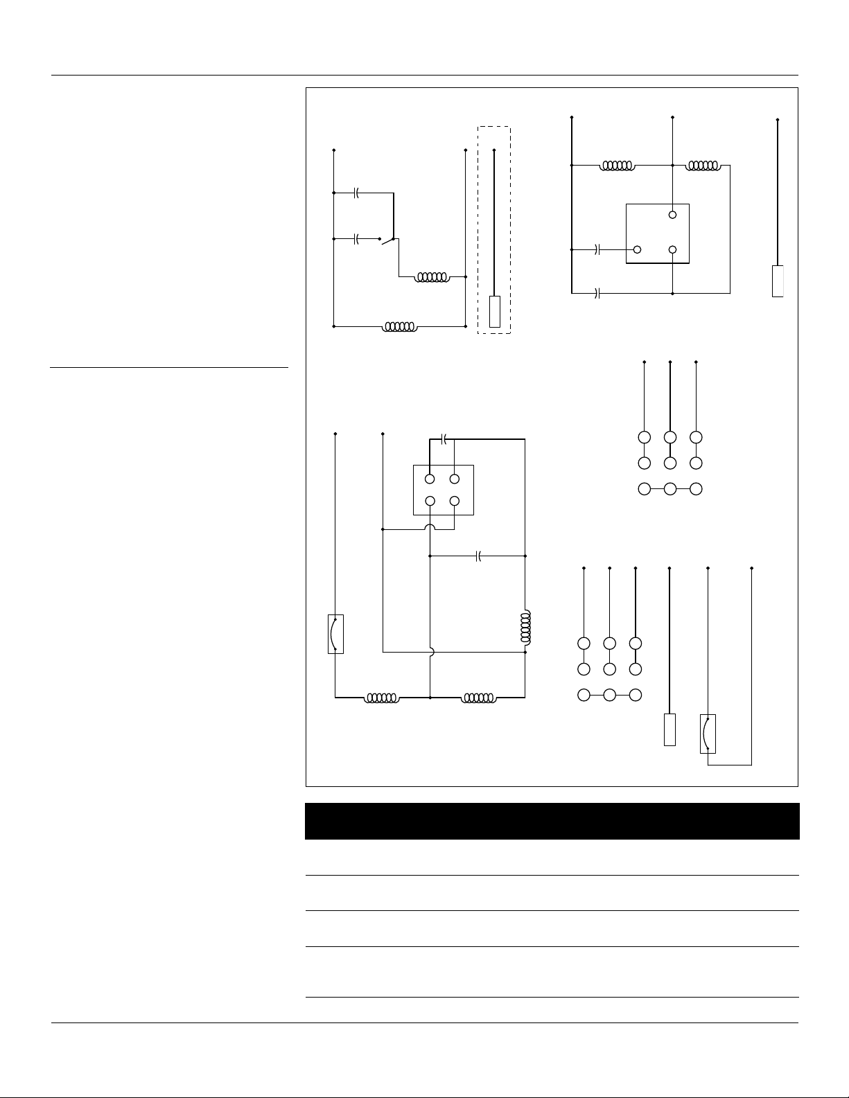
Start Windings
Main Windings
Run Cap.
Start Cap.
Cent Switch
1. WHITE
2. BLACK
3. RED
BAGP1
BADSGP1
1
2 3
7 8 9
4 5 6
1. WHITE
2. BLACK
3. RED
BLUE
Moisture Sensor
Thermal Sensor
WHITE
BROWN
230 Volt 3 Phase
60Hz
BARDSGP1-2023
1. WHITE
2. BLACK
Start Windings
Main Windings
5
2
1
3. RED
Run Cap.
Start Cap.
4. BLUE
Moisture Sensor
BARDSGP1-2021
230 VAC, 1 Phase 60 Hz
Start Relay
Main Windings
Main Windings
Start Windings
4
1
3
2
Start Cap.
Run Cap.
Thermal Sensor
1. WHITE
2. BLACK
4. LEAD
3. RED
230 Volt 1 Phase
60Hz
BAHGP2-2021
230 Volt 3 Phase
60Hz
4 5
718
2
1. WHITE
2. BLACK
6
9
3
3. RED
BAHGP2-2023
4. BLUE
Moisture Sensor
BADSGP1
(only)
Operating Instructions
The double seal grinder pumps contain
an electrode for detecting water within
the unit. The electrode is housed within
the seal chamber, isolated from the
motor chamber by a mechanical shaft
seal. If the electrode detects water
within the oil-filled housing, it will close
the circuit to the alarm light in the
control panel, indicating the motor must
be serviced before the upper mechanical
shaft seal fails. The BLUE conductor is
connected to the seal leak probe.
Refer to Wiring Diagrams for model
specific wiring directions (See Figure 2).
Control Panel and
Level Sensing
BAGP1 & BADSGP1 grinder pumps
have internal start and run capacitors.
No control panel is required for
operating the pump. An alarm box is
recommended for high water alarm.
See Chart 2 for starting component
specifications per model.
BARDSGP1 and BAHGP2 models require
control boxes containing properly sized
start and run capacitors. Single-phase
models require a Single-Phase Control
Box with starting components equal to
specifications listed in Chart 2.
The three-phase models require a ThreePhase Control Box with circuit breaker
and overload heaters per the chart.
Intrinsically safe type float controls are
recommended for all applications. An
intrinsically safe control panel relay will
limit the current and voltage to the level
controls. A control panel can be supplied
with this type of circuitry.
Recommended level sensing settings:
1. The lower “turn-off” control should
be set so the pump stops with the
liquid level at the top of the motor
housing.
2. The upper “turn-on” control should
be set approximately 8” above the
“turn-off” control. This should limit
the number of pump starts to not
exceed 10 starts per hour.
3. The “lag-on” control for duplex
operation should be set 4” above
the “turn-on” control.
4. The “alarm” control is set 10” above
the “turn-on” control.
5. No control should be set above the
inlet pipe.
Figure 2 - Wiring Diagram
Model # Start
BAGP1-115
BADSGP1-115
BAGP1-2021
BADSGP1-2001
BARDSGP1-2021 270-300mF
BAHGP2-2021
BAHGP2-2021C
BAHCP2-2021E1
Chart 2
Capacitor
200mF
250 Vac
270-300mF
250-370 Vac
250-370 Vac
400mF
250 Vac
2 HP Grinder Pumps
Run
Capacitor
70mF
250 Vac
30mF
300 Vac
30mF
300 Vac
90mF
250 Vac
www.waynewatersystems.com
Starting
Relay
NA
NA
GE
3ARR3J3G3
Stearns
477104012401
3
Page 4

Operating Instructions
HP Voltage Phase Breaker Size Heater Size
2 230 3 20 Amp K-50
2 460 3 15 Amp K-33
Chart 3
2 HP Grinder Pumps
Note: If pump is not mounted on a
lift-out rail system, the leg kit needs
to be installed. Set leg height so a 3”
– 4” clearance is achieved between the
bottom pump inlet and basin bottom.
Figure 3 - Leg Kit
Maintenance
Only qualified mechanics with proper
tools and knowledge should attempt to
service this pump.
REPLACING GRINDER IMPELLER AND
SHREDDING RING
Note: This is the only disassembly
operation permitted in the field. All
other repairs must be performed at an
authorized service center or the factory.
Standard Tools Required:
• Standardsocketwrenchset
• Standardsetofopen-end
wrenches
• Hammer
• Visegrippliers
• Allenheadsocketset
• Screwdrivers
• Wirebrush
Disconnect all power
and control wires to
motor at the control panel before starting
the disassembly operations. Do not rely
upon opening the circuit breaker only.
Hazardous cutter.
Rotation of the cutter
with hands in the cutter area can cause
loss of fingers. Keep hands away from
the pump inlet opening when working
on or handling the pump for any reason.
Pump should be
sanitized with bleach
before starting work.
• Pumpshouldbethoroughly
cleaned of trash and deposits
before starting disassembly
operations.
• Wearprotectiveglovesand
clothing.
• Alwaysusearagontheimpeller
when turning to prevent cutting
hands on the sharp edges of the
shredding ring.
DISASSEMBLY OF SHREDDING RING
AND GRINDER IMPELLER
1. Remove 3 bolts from grinder ring
flange with socket wrench. The
grinder ring is pressed into the
flange for convenient removal.
2. Thread 2 of the bolts (removed from
the grinder ring flange) into the
tapped back-off holes in the flange
and evenly tighten the bolts to back
the grinding ring out of the pump
housing.
3. Hold the grinder impeller by prying
against the impeller cutting bar and
remove the cap screw from the end
of the shaft.
4. Use a large screwdriver to the slot
of the shaft and tap on the cutter
vane with a hammer. Tap in a
counterclockwise direction (thread is
right-hand).
5. If the impeller removes easily, clean
and replace if worn.
6. Make sure the pump impeller has
not loosened when the grinder
impeller was removed. This can be
checked on reassembly of grinder
impeller and shredding ring. The
tips of the impeller cutter vanes
should extend 1/8” below the
bottom of the shredding ring. If
the distance is greater, the pump
impeller has loosened. If the
distance is less, shredding ring is not
properly seated.
7. After the volute case has been
removed, wrap emery cloth around
the shaft and hold with vise grip
pliers. Us a cloth on the impeller and
thread tight against shoulder on
shaft.
8. Clean all threads with a wire
brush and file smooth any nicked
threads. Apply an anti-seize or other
graphite compound on threads
before replacing grinder impeller.
9. Make sure cap screw in bottom of
pump shaft is tight. Hold impeller
with screwdriver between the cutter
bar and teeth of shredding ring
while tightening the cap screw.
10. Make sure the impeller turns freely
by hand after reassembly. Some
drag will be present due to the
shaft seals. There should not be any
binding or tight spots when turning
the grinder impeller.
11. If there is any rub or drag on the
shredding ring, loosen the 3 bolts
in the shredding ring plate and
tap lightly with the hammer to
loosen. Retighten the bolts. Be
sure to tighten the bolts evenly,
applying pressure on all 3 bolts. DO
NOT COMPLETELY TIGHTEN ONE
BOLT BEFORE TIGHTENING THE
OTHER BOLTS. THIS WILL CAUSE
MISALIGNMENT AND LOCKING OF
SHREDDING RING AND GRINDER
IMPELLER.
www.waynewatersystems.com
4
Page 5

Operating Instructions
2 HP Grinder Pumps
Troubleshooting
Symptom Possible Cause(s) Corrective Action
Motor Not Running 1. Motor Protector Tripped 1. Allow motor to cool. Make sure pump is completely submerged.
2. Open circuit breaker or blown fuse 2. Reset breaker. If circuit opens repeatedly, don’t reset it. Call a
3. Impeller clogged 3. Check amp draw. If it is more than twice the nameplate amps, the
4. Cutter clogged 4. Disconnect Power, pull pump and inspect cutter and cutter ring.
5. Power cable damaged 5. Resistance between power cable and ground should be infinity. If
6. Bad control panel 6. Inspect control panel wiring. Call a licensed electrician.
7. Defective liquid level switch 7. With switch disconnected from power, check continuity through
8. Not enough liquid in wet well to
activate controls
9. Liquid level cords tangled 9. Untangle cords for free operation.
10. Automatic controls defective 10. Try running pump in manual mode. If it runs, the automatic
Pump runs continuously 1. Liquid level control cords tangled 1. Untangle cords for free operation.
2. Pump is air-locked 2. Stop pump for about one minute and then restart. Repeat
3. Incoming flow exceeds the pump’s
capacity
4. Clogged line 4. Discharge line could be clogged. Unclog line.
Pump delivers low volume
of liquid
Pump cycles frequently 1. No discharge check valve installed 1. Install discharge check valve.
1. Check valve plugged, stuck shut or
installed backwards
2. Systems head is too high 2. Consult dealer.
3. Pump suction plugged 3. Disconnect power, pull pump, inspect and clear as needed.
4. Wrong voltage or not wired correctly 4. Check pump’s rotation, check nameplate voltage against supply
5. Pump air-locked 5. Stop pump for about one minute and then restart. Repeat
6. Worn or damaged impeller 6. Disconnect Power, pull pump and inspect impeller. Replace if
7. Liquid level controls incorrectly
installed or defective
2. Discharge check valve stuck open 2. Repair or replace check valve as necessary.
3. Sewage basin too small 3. Consult dealer.
4. Liquid level controls incorrectly
installed or defective
5. Pump too small for inlet flow 5. Consult dealer about larger pump or second pump.
Clear debris from volute and impeller.
licensed electrician.
impeller is locked. Bearings and shaft may be damaged. Disconnect
Power, clear debris from volute, impeller and cutter as needed.
Replace if worn.
any reading is less than infinity, call a licensed electrician.
switch while activating liquid level switch. Replace switch if
necessary.
8. Allow the liquid to rise several inches above the switch-on level.
control is at fault.
stopping and starting until the airlock clears. If the airlock
continues, Disconnect Power, pull the pump and drill a 1/8” hole
in the discharge pipe between the pump discharge and the check
valve.
3. A larger pump or additional pumps may be required.
1. Make sure check valve is installed correctly and functioning
correctly.
voltage, consult licensed electrician.
stopping and starting until the airlock clears. If the airlock
continues, Disconnect Power, pull the pump and drill a 1/8” hole
in the discharge pipe between the pump discharge and the check
valve.
necessary.
7. Reposition or replace as necessary.
4. Reposition or replace as necessary.
www.waynewatersystems.com
5
Page 6

Operating Instructions
1
2
3
4
5
6
7
8
9
10
11
12
13
14
15
16
17
18
17
16
15
14
13
12
11
10
9
8
7
6
5
4
3
2
1
2 HP Grinder Pumps
For Replacement Parts or Technical Assistance, Call 1-888-636-6628
or log onto our web-site at: www .waynewatersystems.com
Please provide following information: Address any correspondence to:
- Model number Blue Angel Pumps
- Serial number (if any) 101 Production Drive
- Part description and number as shown in parts list Harrison, OH 45030 U.S.A.
Service Parts
Figure 4 - BAGP1 Grinder Pump
SERVICE KITS
Cord Cap
Assembly
(1 and 4)
Capacitors
(2 and 3)
Capacitors
(2 and 3)
Motor Assembly
(5, 6, 7, 8, 9, 10,
11, 12 and 14)
Motor Assembly
(5, 6, 7, 8, 9, 10,
11, 12 and 14)
Mechanical Shaft
(13)
Pump Impeller
(15)
Volute
(16)
Grinder Assembly
(17 and 18)
63014-001
63015-001
BAGP1-115
63030-001
BAGP1-2021
63016-001
BAGP1-115
63031-001
BAGP1-2021
63017-001
63018-001
63019-001
63020-001
Service Parts
Figure 5 - BARDSGP1 Grinder Series
www.waynewatersystems.com
SERVICE KITS
Cord Cap
Assembly
63021-001
(1 and 2)
Motor Assembly
(3, 4, 5, 6, 7, 8,
63022-001
10 and 11)
Upper Mechanical
6
Seal (9)
Lower Mechanical
Seal (12)
Lower Seal
Housing (13)
Volute (14) 63026-001
Pump Impeller
(15)
Grinder Assembly
(16 and 17)
Starting
Components
(not shown)
63023-001
63024-001
63025-001
63027-001
63028-001
63060-002
Page 7

Operating Instructions
1
17
16
15
14
13
12
11
10
9
8
7
6
5
4
3
2
Power Cord 1
Capacitor (Run) 2
Capacitor (Start) 3
Cord Cap 4
Start Mechanism 5
Upper Motor Plate 6
Upper Ball Bearing 7
Dielectric Oil 8
Motor Housing 9
Stator 10
Rotor 11
Lower Ball Bearing 12
Upper Mechanical Seal 13
Moisture Detection Probe 14
Upper Seal Housing 15
Lower Seal Housing 16
Lower Mechanical Seal 17
Volute 18
Pump Impeller 19
Flange with Shredding Ring 20
Grinder Impeller 21
2 HP Grinder Pumps
For Replacement Parts or Technical Assistance, Call 1-888-636-6628
or log onto our web-site at: www .waynewatersystems.com
Please provide following information: Address any correspondence to:
- Model number Blue Angel Pumps
- Serial number (if any) 101 Production Drive
- Part description and number as shown in parts list Harrison, OH 45030 U.S.A.
Service Parts
Figure 6 - BAHGP2 Grinder Series
Service Parts
Figure 7 - BADSGP1 Grinder Series
SERVICE KITS
Upper Volute
63006-001
(1)
Upper Impeller
63007-001
(2)
Motor Assembly
(3, 4, 5, 6, 7, 8, 9,
63008-001
10, 11, 12 and 13)
Lower Mechancial
63009-001
Seal
(12)
Lower Impeller
63010-001
(14)
Lower Volute
63011-001
(15)
Grinder Assembly
63012-001
(16 and 17)
Starting
63013-001
Components
(not shown)
SERVICE KITS
Cord Cap
Assembly
63014-001
(1 and 4)
Capacitors
(2 and 3)
Capacitors
(2 and 3)
Motor Assembly
63013-001
BADSGP1-115
63030-001
BADSGP1-2001
63036-001
(5, 6, 7, 8, 9, 10, 11,
12, 13, 14, and 15)
Upper Mechanical
Seal (13)
Lower Mechanical
63023-001
63024-001
Seal (17)
Volute
63026-001
(18)
Pump Impeller
63027-001
(19)
Grinder Assembly
63029-001
(20 and 21)
www.waynewatersystems.com
7
Page 8

Operating Instructions
Limited Warranty
For two (2) years from date of purchase, Blue Angel Pumps will repair or replace, at its option, for the original
purchaser any part or parts of its Sump Pumps or Water Pumps (”Product“) found upon examination by Blue
Angel Pumps to be defective in materials or workmanship. Please call Blue Angel Pumps (1-888-636-6628) for
instructions or see your dealer. Be prepared to provide the model number when exercising this warranty. All
transportation charges on Products or parts submitted for repair or replacement must be paid by purchaser.
This Limited Warranty does not cover Products which have been damaged as a result of accident, abuse, misuse,
neglect, improper installation, improper maintenance, or failure to operate in accordance with Blue Angel
Pumps’ written instructions.
THERE IS NO OTHER EXPRESS WARRANTY. IM PLIED WARRANTIES, IN CLUD ING THOSE OF MER CHANTABIL I TY AND FITNESS FOR A PARTICULAR PUR POSE, ARE LIMITED TO TWO YEARS FROM THE DATE OF
PUR CHASE. THIS IS THE EXCLUSIVE REM E DY AND ANY LIABILITY FOR ANY AND ALL IN DI RECT OR CON SEQUEN TIAL DAM AG ES OR EX PENS ES WHATSOEVER IS EXCLUDED.
Some states do not allow limitations on how long an implied warranty lasts, or do not allow the exclusions or
limitations of incidental or consequential damages, so the above lim i ta tions might not apply to you. This limited
war ran ty gives you specific legal rights, and you may also have other legal rights which vary from state to state.
In no event, whether as a result of breach of contract warranty, tort (including negligence) or otherwise, shall
Blue Angel Pumps or its suppliers be liable for any special, consequential, incidental or penal damages including,
but not limited to loss of profit or revenues, loss of use of the products or any associated equipment, damage
to associated equipment, cost of capital, cost of substitute products, facilities, services or replacement power,
downtime costs, or claims of buyer’s customers for such damages.
You MUST retain your purchase receipt along with this form. In the event you need to exercise a warranty claim,
you MUST send a COPY of the purchase receipt along with the material or correspondence. Please call Blue
Angel Pumps (1-888-636-6628) for return authorization and instructions.
2 HP Grinder Pumps
DO NOT MAIL THIS FORM TO BLUE ANGEL PUMPS. Use this form only to maintain your records.
MODEL NO.: _______________________________ SERIAL NO.: _______________________________
INSTALLATION DATE: _______________________________
ATTACH YOUR RECEIPT HERE
www.waynewatersystems.com
8
 Loading...