


BWLS75
Lawn Sprinkler
Pump
Please read and save these instructions. Read carefully before attempting to assemble, install, operate or
maintain the product described. Protect yourself and others by observing all safety information. Failure
to comply with instructions could result in personal injury and/or property damage! Retain instructions
for future reference.
© 2007 Blue Angel™ Pumps
Description
This pump is a high capacity, self-priming centrifugal pump suitable for lawn
sprinkling or other applications where
large quantities of water are required.
Flammable liquids such as gasoline,
chemicals or corrosive liquids should
never be used with this pump
.
Safety Guidelines
This manual contains information that
is very important to know and understand. This information is provided for
SAFETY and to PREVENT EQUIPMENT
PROBLEMS. To help recognize this
information, observe the following
symbols.
Danger indicates
an imminently hazardous situation which, if not avoided,
will result in death or serious injury.
Warning indicates
a potentially hazardous situation which, if not avoided,
could result in death or serious injury.
Caution indicates a
potentially hazardous situation which, if not avoided,
may result in minor or moderate injury.
Notice indicates
important information, that if not followed, may cause
damage to equipment.
General Safety Information
1. Read these rules and
instructions carefully.
Failure to follow these
instuctions could
cause serious bodily
injury and/or property damage.
!
NOTICE
!
CAUTION
!
WARNING
!
DANGER
Operating Instructions and Parts Manual BWLS Series
This pump is nonsubmersible.
Pump only clear water. Do
not pump flammable or
explosive fluids such as
gasoline, fuel oil,
kerosene, etc. Do not use in a flammable and/or explosive atmosphere.
Personal injury and/or property damage could result.
This pump is not
designed to handle
salt water, brine, laundry discharge or
any other application which may contain caustic chemicals and/or foreign
materials. Pump damage could occur if
used in these applications and will
void warranty.
All wiring must be performed by a qualified
electrician. The pump
must be installed in compliance with all local and national
codes.
2. Connect this product to a grounded
circuit equipped with a ground
fault interruptor device.
3. Before installing this product, have
the electrical circuit checked by an
electrican to ensure proper grounding.
4. BE CERTAIN the pump
power source is disconnected before
installing or servicing
pump.
5. Check motor voltage setting on
motor endplate and make sure the
line voltage of the electrical current
supply is correct.
6. Be sure the water source and piping
is clear of sand, dirt and scale.
!
WARNING
!
NOTICE
!
WARNING
!
DANGER
320200-002 1/07
Debris will clog pump and void warranty.
7. Failure to protect pump and piping
from freezing could cause severe
damage and will void the warranty.
8. Do not run pump dry. Follow priming instructions.
Installation
Protect pump from the elements by
installing in a basement, garage, tool
shed or pump house. Install the pump so
the centerline of the pump is as close as
possible to the water level. Keep installation area clear to provide access for service and maintenance. Protect the pump
against flooding and excess moisture.
Make sure the pump has adequate ventilation. The surrounding temperature
should not exceed 100
o
F (38oC) or nui-
sance tripping of the motor may occur.
PUMP PIPING INSTALLATION
Use new pipe for best results.
Galvanized or plastic pipe can be used.
When using galvanized pipe, provide
independent supports for both suction
and discharge piping near the pump to
avoid strain on the pump. Minimize use
of elbows and fittings to reduce friction
loss. Refer to the friction loss chart for
specific information.
Increase diameter of suction or discharge piping if length is over 50 feet.
SUCTION PIPING
Install foot valve
or strainer screen
over intake of suction piping.
Never use pipe smaller than 2” in
diameter for suction piping. The suction pipe must be kept free of air leaks.
!
WARNING
MANUAL
The Professional’s Line
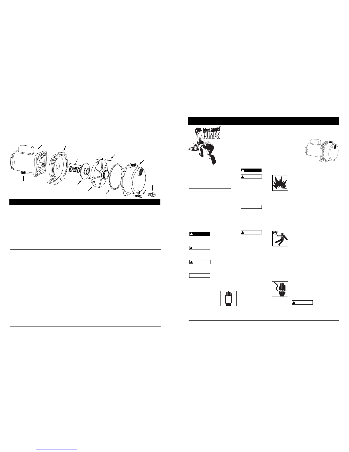
1
2
3
4
5
6
8
7
9
10
11
1 Motor 32031-001 32015-001 32020-001 32021-001 1
2 Tornillo Hex. de 9,5 mm (3/8”) -16 x 2,5 cm (1”) 16334 16334 16334 16334 4
3 Placa selladora 41011-001 41011-001 41011-001 41011-001 1
4 Ensamblaje del sello del eje 15559-002 15559-002 15559-002 15559-002 1
5 Propela 29806-001 29805-001 29804-001 29803-001 1
6 Difusor 29807-001 29807-001 29807-001 29807-001 1”)
7 Tornillo tipo Phillips de 10-24 x 2,5 cm (1”) 67017-001 67017-001 67017-001 67017-001 3
8 Anillo cuadrado 19013-001 19013-001 19013-001 19013-001 1
9 Voluta 41010-001 41010-001 41010-001 41010-001 1
10 Tornillo Hex. de 11,1 mm (7/16”) -16 x 3,2 cm (1.25”) 67018 67018 67018 67018 4
11 Tapón de 6,4 mm (1/4”) NPT 16314-002 16314-002 16314-002 16314-002 1
Para ordenar repuestos comuníquese con el distribuidor
más cercano a su domicilio
Sírvase suministrarnos la siguiente
información:
-Número del modelo
-Número de Serie (de haberlo)
-Descripción y número del repuesto
según la lista de repuestos
Puede escribirnos a:
Blue Angel™
101 Production Drive
Harrison, OH 45030 U.S.A.
No. de Para los Modelos:
Ref. Descripción BWLS75 BWLS100 BWLS150 BWLS200 Ctd.
Garantía Limitada
Durante un año a partir de la fecha de compra del comprador original, la compañía Blue Angel™ reparará o reemplazará, según lo decida, cualquier pieza de
esta bomba de desagüe o bomba de agua que se encuentre defectuosa debido a materiales usados o procesos de manofactura. Sírvase llamar a la compañía Blue
Angel™ (800-237-0987, desde EUA) para recibir instrucciones al respecto o comuníquese con el distribuidor más cercano a su domicilio. Para hacer reclamos bajo
esta garantía deberá suministrarnos el número del modelo y el número de serie del producto. El comprador será responsable de pagar todos los gastos de flete
para enviar las piezas o el producto para que sean reparados o reemplazados.
Esta garantía Limitada no cubre los daños que sufra el producto debido a accidentes, abusos, usos inadecuados, negligencia, instalación incorrecta, mantenimiento inadecuado o haberse utilizado sin seguir las instrucciones escritas suministradas por la compañía Blue Angel™.
NO EXISTEN OTRAS GARANTIAS EXPRESAS. LAS GARANTIAS IMPLICITAS INCLUYENDO GARANTIAS EN RELACION AL MERCADEO O USOS ESPECIFICOS ESTAN LIMITADAS A UN AÑO A PARTIR DE LA FECHA DE COMPRA. ESTA ES LA UNICA GARANTIA DISPONIBLE Y TODAS LAS REPONSABILIDADES
CIVILES, DIRECTAS O INDIRECTAS, O GASTOS POR DAÑOS INDIRECTOS O CONSECUENTES QUEDAN EXCLUIDOS.
Algunos estados no permiten que se establezcan límites en la duración de las garantías implicitas o no permiten que se excluyan ni se establezcan límites en los
daños por incidentes o consecuencias, por lo tanto los límites antes mencionados podrían ser no válidos. Esta Garantía Limitada le otorga derechos legales
especificos, y usted también puede tener otros derechos que varian de un Estado a otro
.
En ningún caso, bien sea por ruptura del contrato de la garantía, responsabilidad civil (incluyendo negligencia) u otra causa, Blue Angel™ o sus distribuidores
serán responsables pon daños especiales, consecuentes ni circunstanciales ni penales, incluyendo, pero no limitados a la pérdida de ganancias, pérdida de uso del
producto o equipos asociados, daños a equipos asociados, costos de capitales, costos para substituir productos, costos para substituir o reemplazar servicios, costos
por pérdida de productividad, o reclamos de clientes del comprador por dichos daños.
DEBE conservar el recibo de compra con esta garantía. En caso de que necesite hacer un reclamo bajo esta garantía, DEBERA enviarnos una copia del recibo
junto con el material o correspondencia. Sírvase comunicarse con la compañía Blue Angel™ (800-237-0987, en EUA) para recibir autorización e instrucciones para
enviar el producto.
NO ENVIE ESTA GARANTIA A WAYNE. Use este documento sólo para mantener sus records.
NO DEL MODELO _______________ NO DE SERIE __________________________ FECHA DE INSTALACION _____________
ANEXE SU RECIBO AQUI
Manual de Instrucciones y Lista de Repuestos
For parts, product & service information
visit www.blueangelpumps.com
Problema Posible(s) Causa(s) Acción a Tomar
Diagnóstico de Averías
El motor no funciona
El motor se recalieenta
y el sistema de protección lo apaga
El motor funciona pero
la bomba no suministra agua
Nota: Ante todo
chequée el sistema de
cebado. Sáquele el
tornillo del sistema de
cebado y vea si el orificio está lleno de agua.
La bomba no le suministra agua a la capacidad máxima
1. El interruptor está en “off”
(apagado)
2. El fusible está quemado
3. El interruptor está dañado
4. Los cables eléctricos del
motor están flojos,
desconectados o mal conectados
1. Los cables del motor están
mal conectados
2. El voltaje es muy bajo
3. La envoltura de la bomba
no está bien ventilada
1. Después de instalar la bomba
en un sitio dife-rente, la
bomba no completó el proceso de cebado debido a:
a. Cebado incorrecto
b. Fugas de aire
c. Fugas en la válvula de pie
2. La bomba perdió el cebado
debido a:
a. Fugas de aire
b. El nivel de agua inferior
a la distancia de succión
de la bomba
3. La propela está obstruída
4. La válvula de chequeo o la
válvula de pie están atascadas en la posición cerrada
5. Las tuberías están congeladas
6. La válvula de pie y/o el
colador están enterrados en
arena o lodo
1. El nivel de agua del pozo es
inferior a lo estimado
2. Las tuberías de acero (de
usarlas) están oxidadas o
alcalizadas, ocasionando
fricción excesiva
3. Las tuberías son muy
pequeñas
1. Cerciórese de que el interruptor esté en “ON” (encendido)
2. Reemplace el fusible
3. Reemplace el interruptor
4. Vea las instrucciones del alambrado. Chequée y conecte bien
todos los alambres
El voltaje del capacitador podría
ser peligroso. Para descargarlo
tóquelo con un desarmador aislado. CERCIORESE de sostener el
desarmador por el mango aislado cuando esté haciendo contacto
con los terminales del capacitador.
1. Vea las instrucciones del alambrado
2. Consúltele a la compañía de eléctricidad. Instale alambres más
resistentes si los disponibles no son adecuados (Vea la tabla de
almabrado)
3. Cerciórese de que la bomba tenga suficiente ventilación para
enfriar el motor
1. Instalación nueva:
a. Siga las instrucciones para cebar la bomba
b. Chequée todas las conecciones de la línea de succión
c. Reemplace la válvula de pie
2. Instalaciones actuales:
a. Chequée todas las conecciones de la línea de succión y el
sello del eje
b. Baje la línea de succión y cebe la bomba una vez más. Si no
logra alcanzar el nivel del agua en el tanque con la tubería
de succión, deberá utilizar una bomba para pozos profundos
3. Limpie la propela
4. Reemplace las válvulas de chequeo o de pie
5. Descongele las tuberías. Entiérrela por debajo de la línea de
congelamiento. Caliente el pozo o el sitio donde tenga almacenada la bomba
6. Coloque la válvula de pie y/o el colador por encima del fondo
del pozo
1. Quizás necesite usar una bomba de propulsión para pozos
profundos (si el agua está a más de 7,6 metros (25’)
2. Reemplace las tuberías con tuberías de plástico donde sea
posible, de lo contrario use tuberías de acero nuevas
3. Use tuberías más anchas
!
ADVERTENCIA
Serie BWLS
19 Sp
Manual de Instrucciones y Lista de Repuestos
2
Operating Instructions and Parts Manual
Installation (Continued)
For horizontal runs, lay pipe from the
water source so the upward slope is at
least 1/2” per foot. This eliminates
trapped air. The threaded inlet of the
pump is 2” NPT.
Do not install suction piping near
swimming areas.
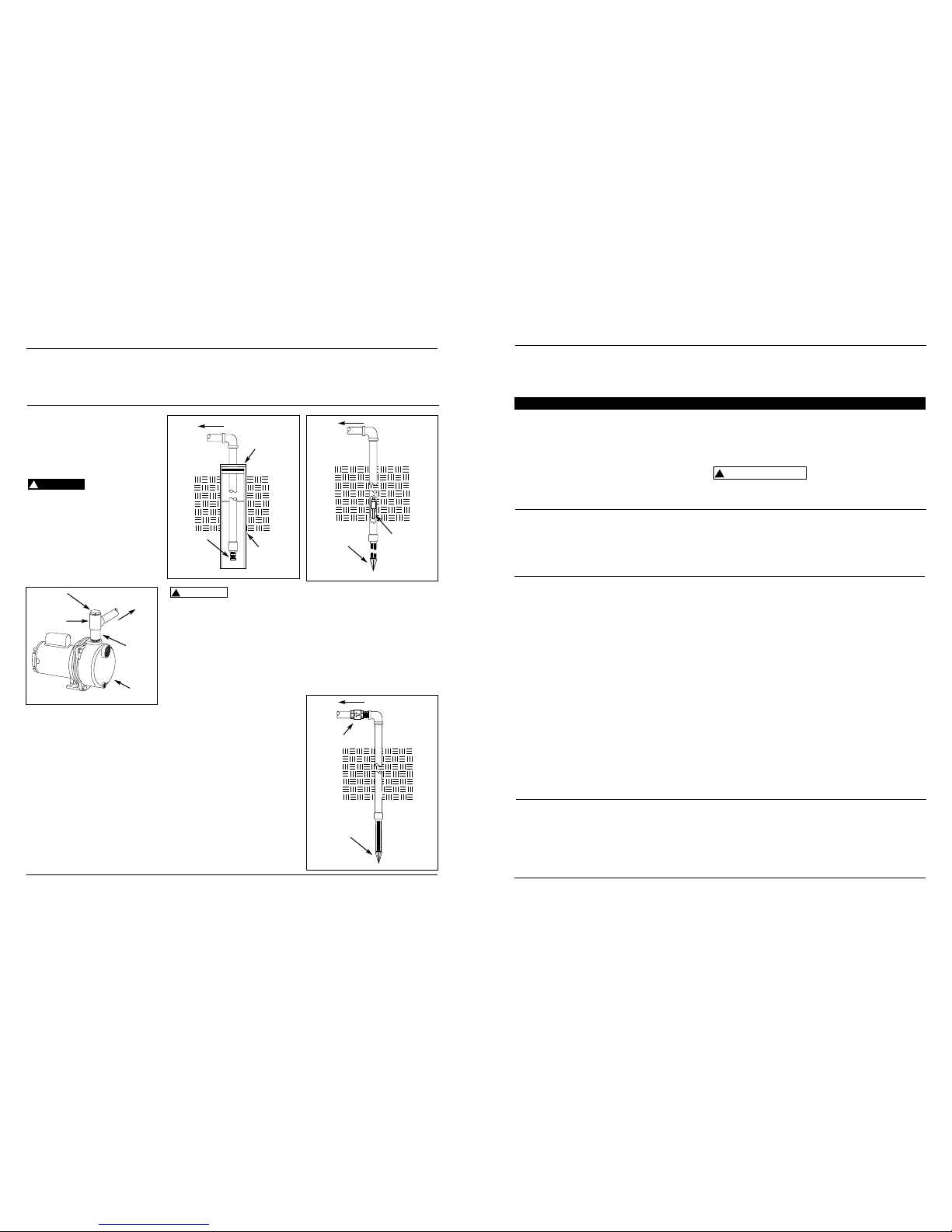
DISCHARGE PIPING
Install a 1-1/2” pipe tee in the pump
discharge to allow easy priming. Plug
the end of the tee opposite the pump
to allow the branch piping to go to the
spray nozzles (See Figure 1). Remove
the pipe plug to fill the pump with
water for priming.
CONNECTION TO WATER SOURCE
The maximum vertical suction lift from
pump to the water level is 25 feet.
DRILLED WELL
1. Install a foot valve on the first section of pipe (see Figure 2).
2. Lower the pipe into the well.
3. Add pipe until the foot valve is 10
feet below the lowest anticipated
water level.
Leaking joints or couplings will allow
air to leak into the pipe and cause poor
pump operation. Make sure to use
pipe joint compound or Teflon
®
tape on
all pipe connections.
!
DANGER
Locate foot valve
no closer than 2
feet from the bottom of the well so
sand or sediment is not drawn into the
system.
4. After the proper depth is reached,
install a well seal or pitless adapter
to support the pipe.
5. Slope the horizontal pipe upward
toward the pump to eliminate trapping air.
6. When using a foot valve, a priming
tee and plug above the well seal is
recommended.
DRIVEN WELL
1. Drive the point several feet below
the water table.
NOTE: A packer-type foot valve can be
installed in the well (See Figure 3). This
type of foot valve allows the well pipe
to be filled with water when priming
and makes the inlet pipe much easier
to test for leaks. Follow the manufacturer’s instructions when installing the
packer-type foot valve.
As an alternative, an in-line check valve
can be used with a driven well (See
Figure 4).
!
CAUTION
It may be necessary to supply the
pump with multiple well points to
maintain the high flow capability of
this pump. Consult with a plumbing
professional for appropriate materials
and installation instructions.
Leaking joints or couplings will allow
air to leak into the pipe and cause poor
pump operation. Make sure to use
pipe joint compound or Teflon
®
tape on
all pipe connections.
Lawn Sprinkler Pump
To Pump
Well Seal
Well
Casing
Foot Valve
Figure 2
Drive Point
Figure 3
To Pump
Packer Type
Foot Valve
To Pump
Inline Check Valve
Drive Point
Figure 4
Pipe Plug
To Spray
Nozzles
Short
Section
of Pipe
1-1/2” Pipe
Tee
Pump
Figure 1
www.blueangelpumps.com
Manual de Instrucciones y Lista de Repuestos
Bomba para Regar Césped
18 Sp
agua limpia. Encienda la bomba. Si la
Funcionamiento
(Continuación)
bomba no comienza a bombear agua
en 10 minutos, apáguela y llénela de
agua limpia una vez más.
Si la bomba no funciona después de
varios intentos, chequée lo siguiente:
1. La distancia vertical entre la bomba
y el nivel de agua no debe ser más
de 7,6 metros (25’).
2. Las tuberías de succión deben estar
apretadas herméticamente.
3. Cerciórese de que la(s) válvula(s) de
las tuberías de descarga o de succión estén abiertas (de haberlas).
Nunca
use la
bomba si las tuberías de descarga están
cerradas u obstruídas. El agua dentro
de la bomba podría hervir y dañar la
bomba.
Mantenimiento
El motor de la bomba debe mantenerse
bien ventilado. Los cojinetes del motor
vienen de fábrica lubricados de por vida.
Éstos no necesitan lubricación adicional.
DURANTE EL INVIERNO
Siempre proteja la bomba y las tuberías
!
PRECAUCION
contra temperaturas congelantes. Si
hay peligro de que se congelen, drene
el sistema. Para drenar el sistema:
1. Quítele el tapón al conector en T de
la tubería de descarga.
2. Quítele el tapón de 6,4 mm (1/4”)
ubicado en la parte inferior del
frente de la bomba.
3. Drene todas las tuberías ubicadas
por debajo de la línea de congelamiento.
Capacidad de las Bombas de 3/4 CP en Litros/Hora
Distancia Presión de Trabajo (bar)
en Metros 0,69 1,38 2,07
Capacidad de las Bombas de 1 CP en Litros/Hora
Distancia Presión de Trabajo (bar)
en Metros 0,69 1,38 2,07
Capacidad de las Bombas de 1-1/2 CP en Litros/Hora
Distancia Presión de Trabajo (bar)
en Metros 0,69 1,38 2,07 2,76
Capacidad de las Bombas de 2 CP en Litros/Hora
Distancia Presión de Trabajo (bar)
en Metros 0,69 1,38 2,07 2,76
3,2 cm (1-1/4”) 0,179 0,269 0,379 0,648 0,972
3,8 cm (1-1/2”) 0,083 0,179 0,303 0,462 0,648 1,096
5,1 cm (2”) 0,041 0,055 0,089 0,138 0,193 0,324 0,489 0,689
6,4 cm (2-1/2”) 0,041 0,055 0,083 0,089 0,207 0,289
* Multiplique por 1,8 si usa tubos de acero
Pérdida debido a la fricción por cada 30,5 metros de tubos de plástico bar *
Diám. del (Litres por Hora)
Tubo 4,542 5,678 6,814 9,085 11,356 13,627 18,170 22,712 27,255
1,5 14,761 12,566 8,781
3 14,308 11,810 7,949
4,6 13,627 11,015 4,504
6,1 12,302 10,107 3,747
7,6 11,394 9,690 3,179
1,5 16,693 14,838 9,728
3 15,823 13,324 8,706
4,6 14,498 12,643 6,738
6,1 13,930 11,583 4,391
7,6 12,643 10,296 4,769
1,5 18,132 16,958 13,173 7,797
3 17,450 16,315 12,075 5,753
4,6 16,352 15,293 10,977 0
6,1 14,763 14,081 10,144 0
7,6 14,422 12,491 9,047 0
1,5 22,636 21,046 16,315 11,583
3 20,479 19,759 15,482 10,901
4,6 19,797 18,851 14,763 9,728
6,1 15,595 14,535 13,286 8,365
7,6 15,065 13,627 12,491 0
Operation
Never run the
pump dry. Running
pump without water may cause seal
damage. Fill the pump with water
before starting.
PRIMING THE PUMP
After pump installation is complete,
the pump must be primed. Remove the
pipe plug in the discharge piping and
fill the pump and suction pipe with
clean water. Turn power to pump on. If
the pump does not pump water in 10
minutes, turn off the pump and refill
with clean water.
If the pump does not operate after
repeated attempts, check the following:
1. Vertical distance of pump to water
level must not be over 25 feet.
2. Suction piping must be air tight.
3. Be sure valve(s) are open if used in
discharge or suction piping.
Never run the
pump with a
closed or clogged discharge. The water
inside the pump could boil and damage
the pump.
Maintenance
Maintain adequate ventilation for the
pump motor. The motor bearings are
permanently lubricated at the factory.
Additional lubrication is not required.
!
CAUTION
!
CAUTION
3
Operating Instructions and Parts Manual
Dug Well, Cistern, Lake And
Spring Installation
1. Install a foot valve on the inlet pipe
and lower into the water.
Locate foot valve
no closer than 2
feet from the bottom of the water
source so sand or sediment is not
drawn into the system.
NOTE: When a lake is used for the
water supply, make sure the suction
pipe is deep enough to be submerged
at all times. Slope the pipe upward
toward the pump to eliminate trapping air. The pipe must be removed
during winter months or protected
against freezing.
Protect the pipe
from damage by
swimmers and boaters.
Electrical Connections
Connect the pump to a separate electrical circuit with a dedicated circuit
breaker. Refer to the electrical specifications in wiring chart for recommended circuit breaker and wire size.
Install and maintain wiring for this
pump in accordance with the National
Electrical code and all applicable local
electrical codes.
The motor must be grounded by connecting a copper conductor to the
!
WARNING
!
CAUTION
grounding screw provided within the
wiring compartment.
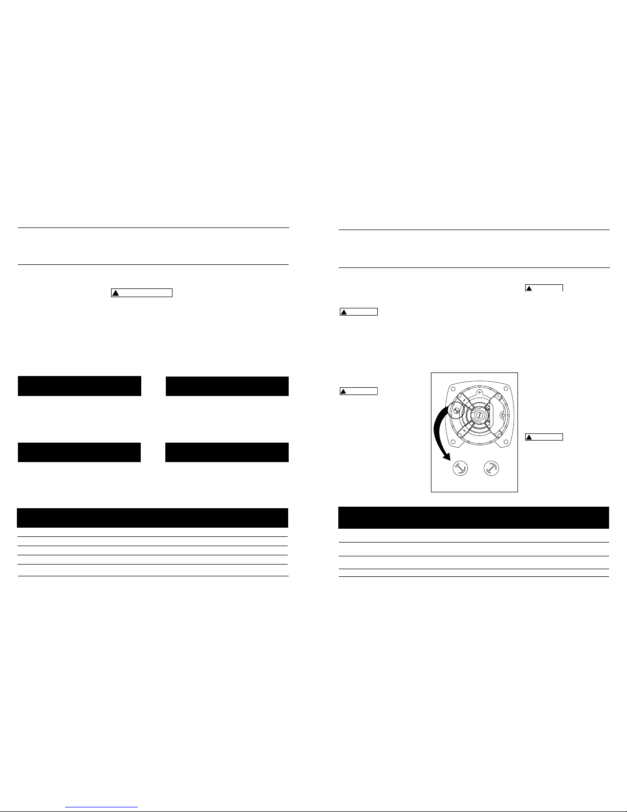
The voltage of power supply must
match the voltage of the pump. The
BWLS75, BWLS100 and BWLS150 have
dual voltage motors preset at the factory to 230 volts. The motors can be
converted to 115 volts by turning the
voltage selector to the desired voltage
(See Figure 5). Use a needle nose pliers
to pull the selector out approximately
1/4”, rotate and then reinsert in correct
position.
The BWLS200 cannot be
converted; the motor is 230 volts
only.
BWLS Series
115 V
230 V
115 V
230 V
Figure 5 - Voltage Selector
BWLS75 3/4 115 13.5 20 12 12 10 10
230 7.0 15 14141212
BWLS100 1 115 14.8 20 12 12 10 10
230 7.4 15 14141212
BWLS150 1-1/2 115 17.0 30 10 10 8 8
230 8.5 15 14141212
BWLS200 2 230 12.0 15 14 14 12 12
Distance in Feet From Motor to Supply
Max. Fuse 0 51 101 201
Load Rating 50 100 200 300
Model HP Volts Amps Amps (AWG Wire Size)
WIRING CHART - RECOMMENDED WIRE AND FUSE SIZES
www.blueangelpumps.com
 Loading...