


BCSE50T
Operating Instructions and Parts Manual
The Professio nal’ s Line
Please read and save these instructions. Read carefully before
attempting to assemble, install, operate or maintain the product
described. Protect yourself and others by observing all safety
information. Failure to comply with instructions could result in
personal injury and/or property damage! Retain instructions for
future reference.
Sewage Pump
BCSE50T, BCSE50M
BCAPSE50 and BCAPSE50-2
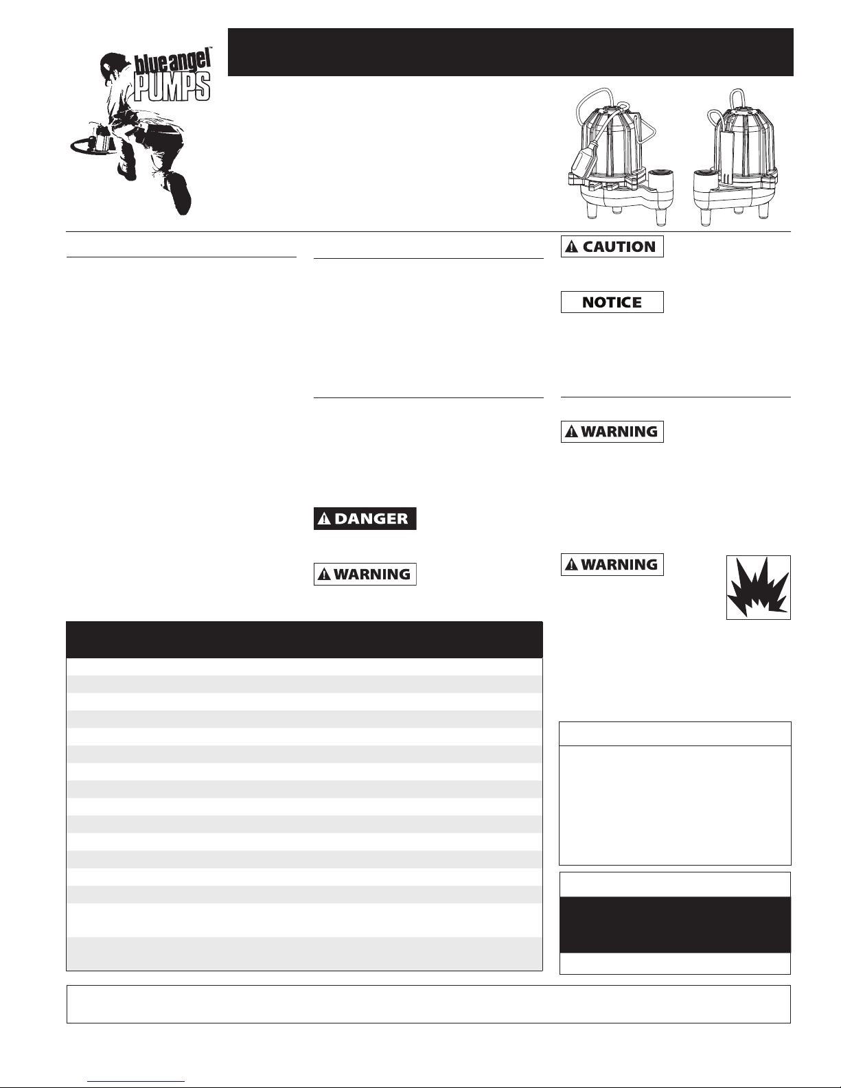
Description
A sewage system consists of a pump,
control switch, and a ba sin for use in ap plica tions where less than six toilets (units)
are dis charged into the basin. The sys tem is
generally con trolled by a float switch with a
plug-in-plug which accepts the pump plug
and in turn plugs into a 120 volt outlet.
BCSE50T models utilize a wide angle
differential float switch that rises with the
liquid level and turns the pump on. As
the liquid level decreases the float lowers
and turns the pump off. The BCAPSE50
is provided with a solid-state electronic
capacitive water level control. When
water is detected, the pump will start
automatically. This pump is in tend ed for
use in do mes tic sewage lift stations. It is
suitable for pumping sewage, effluent,
wastewater, groundwater and other non
-ex plo sive, non-cor ro sive liquids with up
to 2 inch solids. Not approved for outdoor
use. Pump contains oil which is poisonous
to aquatic life. Do not use in ponds or
water features.
Specifications BCSE50M & BCSE50T
Power supply requirements 120V, 60 hz 120V, 60hz
Circuit requirements 15 amps (min) 15 amps (min)
Motor duty Intermittent Intermittent
Motor 120V, 1 Phase 120V, 1 Phase
Horsepower 1/2 1/2
Motor full load 8.7 amps 8.7 amps
Liquid temperature range 40°F to 120°F 40°F to 120°F
Max. operating position 45° from vertical 45° from vertical
Dimensions 14 inch x 12 inch 14 inch x 12 inch
Intake 2 inch 2 inch
Discharge 2 inch NPT female 2 inch NPT female
Cut-in level (factory set) 19 inch 11 inch
Cut-out level (factory set) 9 inch 3 inch
Differential 10 inch 7 inch
Switch 90° wide angle
mechanical tether switch
Power cord 16 gauge 3 conductor
with plug
Unpacking
Inspect this unit before it is used.
Occasionally, products are damaged
during shipment. If the pump or
components are damaged, return
the unit to the place of purchase for
replacement. Failure to do so could
result in serious injury or death.
Safety Guidelines
This manual contains information
that is very important to know and
understand. This information is
provided for SAFETY and to PREVENT
EQUIPMENT PROBLEMS. To help
recognize this information, observe the
following symbols.
Danger indicates
an imminently
hazardous situation which, if not avoided,
WILL result in death or serious injury.
Warning indicates
a potentially
hazardous situation which, if not avoided,
COULD result in death or serious injury.
BCAPSE50 &
BCAPSE50-2
Capacitive water sensor
16 gauge 3 conductor
with plug
Caution indicates
a potentially
hazardous situation which, if not avoided,
MAY result in minor or moderate injury.
Notice indicates
important
information, that if not followed, may
cause damage to equipment.
General Safety
Information
CALIFORNIA PROPOSITION 65
This product or its
power cord contains
chemicals known to the State of
California to cause cancer and birth
defects or other reproductive harm.
Wash hands after handling.
GENERAL SAFETY
1. Know the pump application,
limitations, and po ten tial hazards.
Do not
use to
pump flammable or
explosive fluids such
as gasoline, fuel oil,
kerosene, etc. Do not
use in a flammable and/or explosive
atmosphere. Use pump only with liquids
compatible with pump component
materials. Failure to follow this
warning can result in personal injury
and/or property damage.
Construction
Motor
body material .......... Cold rolled steel
Motor housing ...................... Cast iron
Volute .................................... Cast iron
Impeller .............. Glass reinforced PBT
Seal plate .............................. Cast Iron
Shaft seal ........................... Mechanical
Performance
GALLONS PER MINUTE AT TOTAL
HEAD IN FEET
5 10 15
113 90 33
REMINDER: Keep your dated proof of purchase for warranty purposes!
Attach it to this manual or file it for safekeeping.
© 2009 Blue Angel™ Pumps
For parts, product & service information
visit www.blueangelpumps.com
330505-002 12/09
Operating Instructions and Parts Manual
TEST
RESET
General Safety
Information
(continued)
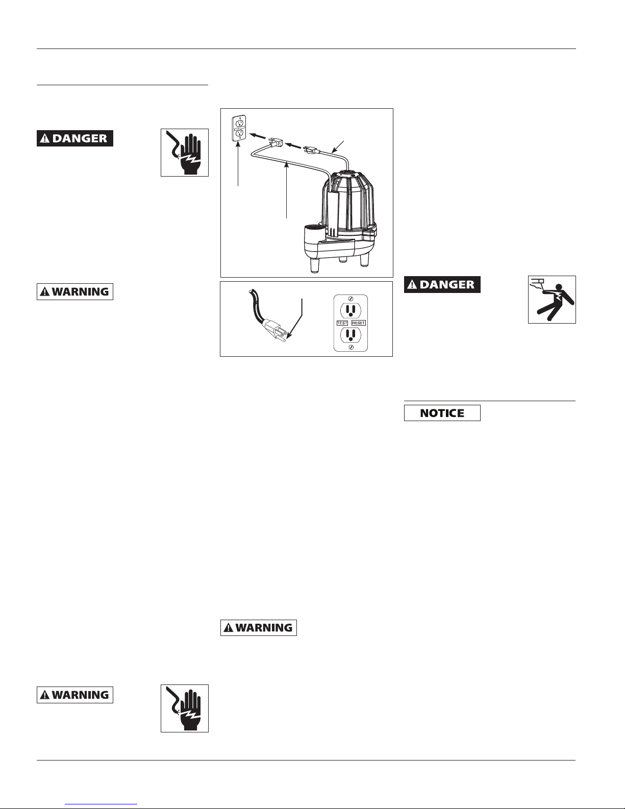
11. This equipment is only for use on
120 volt (single-phase) and is
equipped with an ap proved 3-con ductor cord and 3-prong, grounding-type
2. Make certain that the power source
plug as shown in Fig ure 1A and 1B.
(electric motor) conforms to the
requirements of the equipment.
Disconnect power before
servicing. If the power
dis con nect is out of sight,
lock in the open po si tion and tag it
to prevent unexpected application of
power. Failure to do so could result in
fatal electrical shock!
3. Release all pressure within the
system before ser vic ing any
component.
4. Drain all liquids from the system
Grounded
outlet
Capacitive
water sensor
Figure 1A
Pump Power
Cord
Plug
before servicing.
This pump contains
dielectric motor oil for
motor heat transfer. Care should be taken
when disposing of this oil. Do not use this
pump in ponds or fountains because the
motor oil can be harmful to aquatic life.
5. Secure the discharge line before
Figure 1B
Grounding blade
starting the pump. An unsecured
discharge line will whip, possibly
causing personal injury and/or
property damage.
6. Check hoses for weak and worn
condition before each use, making
certain that all connections are secure.
7. Periodically inspect the pump and
system com po nents. Perform routine
maintenance as required (See
Maintenance Section).
8. Provide a means of pressure relief
for pumps whose discharge line can
be shut-off or obstructed.
9. Personal Safety:
a. Wear safety glasses at all times
when working with pumps.
b. Keep work area clean, uncluttered
and properly lighted; replace all
unused tools and equipment.
c. Keep visitors a safe distance from the
work area. Make workshop childproof with pad locks, master switch es,
and by re mov ing starter keys.
10. When wiring an elec tri cal ly driven
pump such as this, fol low all electrical
and safety codes, as well as the most
recent National Electrical Code (NEC)
and the Oc cu pa tion al Safety and
Health Act (OSHA).
Risk of
electric
shock! Never connect the
green (or green and yellow)
wire to a live terminal!
To reduce the risk of electric shock, the
motor must be securely and adequately
grounded. This can be ac com plished by
the following:
• Insertingplugdirectlyintoa
properly installed and grounded
3-prong, grounding-type re ceptacle
(as shown in Figure 1A and 1B).
• Permanentlywiringtheunitwitha
grounded, metal raceway system.
• Othersuitablemeans.
Where a 2-prong wall receptacle is
encountered, it must be replaced with
a properly grounded 3-prong re cep tacle installed in accordance with the NEC
and local codes and ordinances.
12. All wiring should be performed by a
qualified elec tri cian.
13. It is strongly recommended that this
unit is plugged into a Ground Fault
Circuit Interrupter (GFCI). Con sult a
local electrician for installation and
availability.
The pump motor
is equipped with
automatic resetting thermal protector
and may restart unexpectedly. Protector
tripping is an indication of motor
overloading as a result of operating
the pump at low heads (low discharge
restriction), excessively high or low
voltage, inadequate wiring, incorrect motor
conditions, or a defective motor or pump.
14. This pump is designed to transfer
water in cycles. Using this pump in
a continuous duty application by
ma nip u lat ing the switch to stay on,
will affect the per for mance and the
life of the product.
15. Protect electrical cord from sharp
objects, hot sur fac es, oil, and
chemicals. Avoid kinking the cord.
Re place or repair damaged or worn
cords im me di ate ly. Use wire of
adequate size to minimize voltage
drop at the motor.
16. Do not handle a pump or pump
motor with wet hands or when
standing on a wet or damp surface,
or in water.
17. Do not hang this product by the
carry handle. Sewage pumps
should be set firmly on their legs
and supported by rigid piping. This
eliminates twisting and damage
during pump operation.
18. Do not use an extension cord.
Do not
walk on
wet area until all power has
been turned off. If the shutoff box is in basement, call
the electric company to shut-off service to
the house, or call the local fire department
for instructions. Remove pump and repair
or replace. Failure to follow this warning
can result in fatal electrical shock.
Installation
In any installation
where property
damage and/or personal injury might result
from an inoperative or leaking pump due to
power outages, discharge line blockage or
any other reason, use a backup system(s).
1. Thread the discharge pipe or
pipe nipple into the dis charge
connection.
2. If a check valve is used in a solids
handling system mount the check
valve in a horizontal position or at
a 45º angle with the valve pivot on
top. In a vertical position, solids will
tend to lodge on the valve flapper
and can prevent it from opening.
3. Drill a 1/8 inch hole in the discharge
pipe ap prox i mate ly 1 inch to 2 inch
above the pump discharge when a
check valve is used. The hole prevents
air locking of the pump at the initial
start-up and if it should lose prime.
4. A gate valve should be installed in the
system after the check valve. This gate
valve should be a full port valve which
will pass 2 inch solids or as required
by state and local codes. This gate
valve permits removal of the pump
and/or check valve for servicing.
5. A union should be installed between
the check valve and the pump so the
pump can be removed with least
disturbance of the piping.
www.blueangelpumps.com
2
BCSE50T, BCSE50M
BCAPSE50 and BCAPSE50-2
General Safety
Information
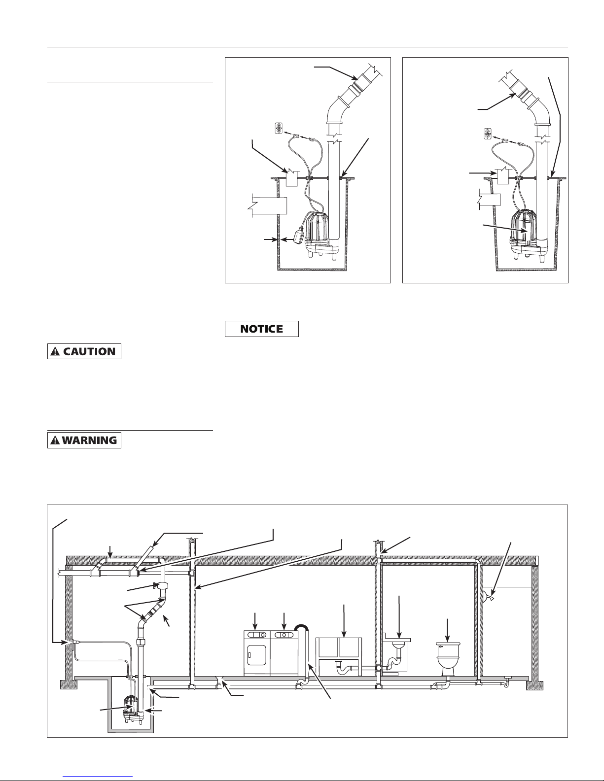
6. BCSE50T models are supplied with
a detachable tether switch with a
piggyback plug (see figure 3A). The
length of the tether (distance of cord
from float to clamp) should not be set
shorter than 3-1/4 inches and should
not be used in a basin smaller than 14
inches in diameter. If using a differential
other than the factory setting, be sure
when the pump shuts off at least 4
inch of fluid is left in the basin so the
impeller remains submerged.
7. BCAPSE50 models are supplied with
an capacitive water sensor. Orient the
pump in the basin so that the water
sensor is 180° away from the inlet.
Make certain the incoming water
stream does not hit the capacitive
surface (See Figure 3B).
8. When a tether switch is used, rigid
dis charge pipe is required. If the
pump is allowed to move, the
tether switch could be re strict ed
by the basin wall, pre vent ing the
pump from operating.
Before removing
for service, always disconnect electrical
power to pump and control switch. For
any work on pump or switch, ALWAYS
unplug the power cord. Do not just turn
off circuit break er or unscrew fuse.
(continued)
pump from basin
Maintenance
Make certain that
unplugged before attempting to service
or remove any component. This pump is
assembled in the factory using special
equipment; therefore only authorized
service dealers or qualified electricians
the pump is
Check valve 45º
Vent
Inlet
1/2 inch
Min.
Clearance
Figure 3A - Prefabricated Basins
should attempt to repair this unit.
Improper repair can cause an electrical
shock hazard.
The pump contains
oil that may be
under pressure because of heat. Let the
pump cool for a minimum of two hours
before servicing this unit.
Gasket
Basin
1. Disassembly of the motor prior to
expiration of war ran ty will void the
warranty. It might also cause internal
leakage and damage to the unit. If
repairs are required, return the pump
to the dealer from whom it was
pur chased or call 1-888-636-6628. If
motor is ever disassembled the o-rings
must be replaced. Care must be taken
to ensure that all seals do not leak.
Gasket
Check
valve 45º
Vent
*Orient the pump so that
the switch is 180° away
from the inlet. Make sure
the incoming water stream
does not hit the switch
surface.
Figure 3B - Prefabricated Basins
Inlet
Basin
2. After the basin cover is removed
and necessary dis charge piping
disconnected, lift pump from basin.
3. Pump should be checked on a
regular basis for proper op er ation. If anything has changed since
unit was new, the unit should be
removed and repaired or replaced.
Only qualified electricians or service
peo ple should at tempt to repair
this unit. Improper repair and/or
assembly can cause an electrical
shock hazard.
4. Place the pump in a suitable area
where it can be cleaned thoroughly.
Remove all scale and deposits on pump.
5. Submerge the complete pump in a
disinfectant so lu tion (10% chlorine
bleach solution) for at least one
hour before handling the pump.
Three prong grounded outlet equipped
with a ground fault interruptor
2 inch Discharge pipe
2 inch
Gate Valve
45º Elbow
2 inch
Check
Valve
Float
switch
Flange
Sewage pump passes
2 inch dia. solids
Upper level
drainage
Cleanout
WasherDryer
Floor drain
Vent pipe
Laundry tubs
Washer drain
3
Vent pipe
Lavatory
Shower
Toilet
Figure 2 - Typical Installation
www.blueangelpumps.com

Operating Instructions and Parts Manual
Maintenance (continued)
6. Clean all dirt and deposits from the
pump float. Make sure float moves
freely after cleaning.
7. Clean all dirt and deposits away
from pump inlet and volute.
This pump contains
dielectric motor
oil for lubrication and motor heat
transfer. This oil can be harmful to the
environment. Check state environmental
laws before disposing of this oil. This
oil can be harmful to aquatic life so
consideration should be exercised in the
application of this pump.
Troubleshooting Chart
Symptôm Possible Cause(s) Corrective Action
Pump will not start
or run
Pump starts and
stops too often
1. Water level too low
2. Blown fuse or tripped circuit breaker
3. Low line voltage
4. Defective motor
5. Defective switch
6. Impeller (pump filled with debris)
7. Tangled tether switch
(BCSE50T & BCSE50M)
8. Insufficient liquid level
1. Back flow of water from piping
2. Dirty capacitive water sensor
3. Faulty float switch
4. Check valve not installed or leaking
5. Discharge head is less than
manufacturer's minimum
1. Pump switch will not turn on unless water covers top of pump
2. If blown, replace with proper sized fuse or reset breaker
3. If voltage is under recommended min i mum, check wiring size from the
main switch on property. If OK, contact power company.
4. Return for service or replace motor
5. Replace float switch
6. If impeller will not turn, remove housing and remove debris
7. Arrange switch so the switch moves free ly. Re po si tion pump if
necessary
8. Make sure liquid level is at least 13 inches from the basin floor
1. Install check valve
2. Reposition pump, clean sensor face
3. Replace float switch
4. Remove and examine check valve for prop er in stal la tion and free
operation
5. Recheck all sizing calculations to determine proper pump size
Pump shuts off
and turns on
independently
of switch (trips
thermal overload
protection)
Pump operates
noisily or vibrates
excessively
Pump will not shut
off
Pump operates but
delivers little or no
water
1. Excessive water temperature
2. Defective switch or entangled switch is
causing pump to run dry
(BCSE50T & BCSE50M)
3. Low line voltage
1. Worn bearings
2. Debris in impeller cavity or broken
3. Piping attachments to building
structure too rigid or too loose
1. Float switch movement restricted
2. Restricted discharge (obstruction in
piping)
3. Excessive inflow or pump not properly
sized for application
4. Defective switch
1. Low line voltage
2. Debris caught in impeller or discharge
3. Worn or defective pump parts or
plugged impeller
4. Pump running backwards
5. Pump not properly sized for application
6. Check valve stuck closed or installed
backwards
7. Shut off valve closed
1. Pump should not be used for water above 120º F
2. Replace or reposition pump
Pump may start unexpectedly. Disconnect
power supply before ser vic ing.
3. If voltage is under recommended min i mum, check wiring size from the
main switch on property. If OK, contact power company
1. Return for service or replace
2. Remove housing, clean impeller and/or replace broken impeller
3. Replace portion of discharge pipe with flexible connector
1. Reposition pump or clean basin as required to provide adequate
clearance for float
2. Remove pump and clean pump & piping
3. Recheck all sizing calculation to determine proper pump size
4. Replace float switch
1. If voltage is under rec om mend ed minimum, check wiring size from the
main switch on prop er ty. If OK, contact power company
2. Remove, clean and check for tight ness
3. Replace worn parts or entire pump. Clean parts if required
4. Check rotation. (CCW from bottom) Return if CW
5. Recheck all sizing calculations to determine proper pump size
6. Remove and examine check valve for proper installation and free
operation
7. Open valve
www.blueangelpumps.com
4
BCAPSE50 and BCAPSE50-2
For replacement parts or technical assistance,
call 1-888-636-6628
BCSE50T, BCSE50M
Please provide following information:
- Model number
- Serial number (if any)
- Part description and number as shown in parts list
1
2
3
4
Address parts correspondence to:
Blue Angel Pumps
101 Production Drive
Harrison, OH 45030 U.S.A.
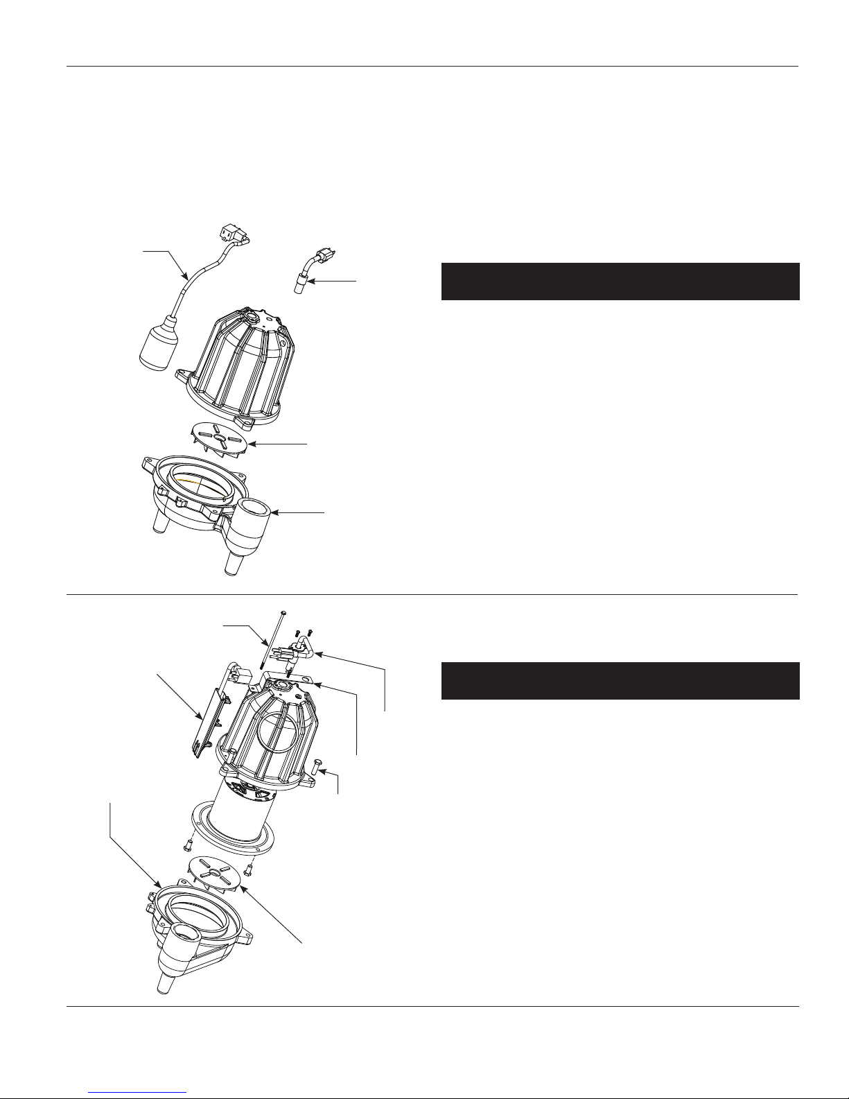
Ref. Part
No. Description Number Qty
1 Mechanical switch Kit
(CSE40T) 30000-009 1
Mechanical switch Kit
(CSE40T-2) 30000-003 1
2 Power cord (CSE40T) 31035-001 1
Power cord
(CSE40M, CSE40T-2) 31036-001 1
3 Impeller 17317-001 1
4 Volute 41027-001 1
7
1
2
5
4
6
3
Ref. Part
No. Description Number Qty
1 Capacitive Water Sensor 30037-002 1
(CBCAPSE50)
Capacitive Water Sensor 30037-004 1
(BCAPSE50-2)
2 Power Cord (BCAPSE50) 31035-001 1
Power Cord (BCAPSE50-2) 31036-001 1
3 Impeller 17317-001 1
4 Volute 41027-001 1
5 Bracket 7434 1
6 Through Bolt 16836-004 1
7 Screw 67050-001 3
www.blueangelpumps.com
5

Operating Instructions and Parts Manual
Limited Warranty
For two years for BCSE50M and BCSE50T and five years for BCAPSE50, BCAPSE50-2 from the date of
purchase, Blue Angel will repair or re place, at its option, for the original purchaser any part or parts of
its Sump Pumps or Water Pumps (“Product”) found upon examination by Blue Angel to be defective in
materials or work man ship. Warranty is limited to a one time replacement. Please call Blue Angel (888-636-
6628) for instructions or see your dealer. Be pre pared to provide the model number, serial number and
dated receipt when exercising this warranty. All transportation charges on Products or parts submitted for
repair or replacement must be paid by purchaser.
This Limited Warranty does not cover Products which have been damaged as a result of accident, abuse,
misuse, neglect, improper installation, improper maintenance, or failure to operate in accordance with Blue
Angel’s written instructions.
THERE IS NO OTHER EXPRESS WARRANTY. IMPLIED WARRANTIES, IN CLUD ING THOSE OF MER CHANTABIL I TY AND FITNESS FOR A PARTICULAR PUR POSE, ARE LIMITED TO TWO YEARS FOR BCSE50M AND
BCSE50T, AND FIVE YEARS FOR BCAPSE50 FROM THE DATE OF PURCHASE. THIS IS THE EXCLUSIVE
REM E DY AND ANY LIABILITY FOR ANY AND ALL INDIRECT OR CONSEQUENTIAL DAM AG ES OR
EXPENSES WHATSOEVER IS EXCLUDED.
Some states do not allow limitations on how long an implied warranty lasts, or do not allow the exclusions
or limitations of incidental or consequential damages, so the above lim i ta tions might not apply to you. This
limited warran ty gives you specific legal rights, and you may also have other legal rights which vary from
state to state.
In no event, whether as a result of breach of contract warranty, tort (in clud ing negligence) or otherwise,
shall Blue Angel or its suppliers be liable for any special, consequential, incidental or penal damages
including, but not limited to loss of profit or revenues, loss of use of the products or any associated
equipment, damage to associated equip ment, cost of capital, cost of substitute products, facilities, services
or replacement power, downtime costs, or claims of buyer’s cus tom ers for such damages.
You MUST retain your purchase receipt along with this form. In the event you need to exercise a warranty
claim, you MUST send a copy of the purchase receipt along with the material or correspondence. Please call
Blue Angel (888-636-6628) for return authorization and instructions.
DO NOT MAIL THIS FORM TO Blue Angel. Use this form only to maintain your records.
MODEL NO.__________________ SERIAL NO.____________________ INSTALLATION DATE_____________________
ATTACH YOUR RECEIPT HERE
www.blueangelpumps.com
6
 Loading...