

Page 1
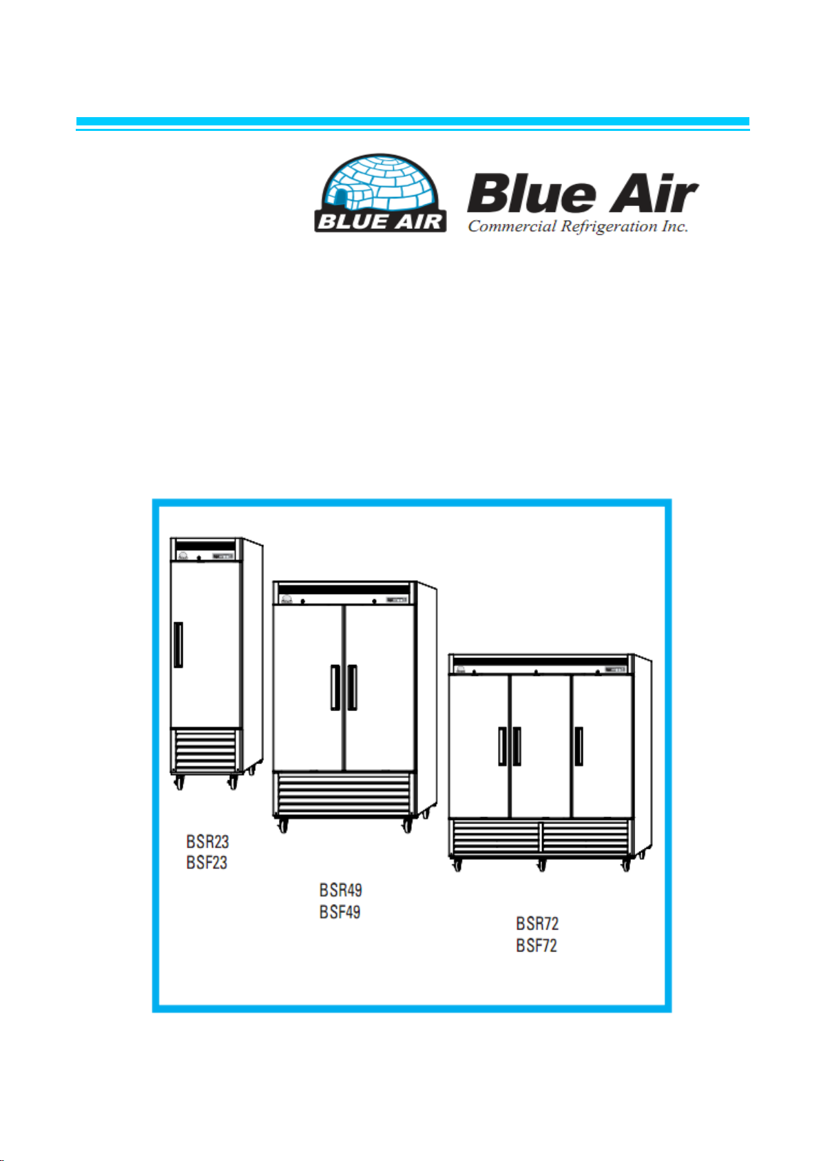
Commercial
Upright Refrigerator & Freezer
Service Manual
Page 2

TABLE OF CONTENS
1. ASSEMBLY …………………………………………………… 4~11
2. PARTS …………………………………………………………… 12~26
3. WIRING DIAGRAM …………………………………………… 27~28
4. PART DETAILS …………………………………………………. 29~33
5. MAIN COMPONENTS …………………………………………. 34~47
6. ELECTRONIC CONTROL INSTRUCTIONS ……………… 48~55
7. REPLACEMENT OF MAIN COMPONENTS ………………. 56~72
8. PART LIST ……………………………………………………… 73~76
.
Page 3
Safety cautions during service
ㆍ When exchanging or repairing electric parts, pull the plug out before
exchanging and repairing.
ㆍ When exchanging electric parts, use a rating part.
- Be sure to check marks such as MODEL name, rating voltage,
rating currents, movement temperature etc.
ㆍ During repairing, make sure wirings such as HARNESS, WIRE JOINT are
sturdy
so that it is free of danger due to disclosure of core wire.
- Don’t let it derail when certain strength is put on.
ㆍ When repairing, take out the dust or foreign body (Housing part, wiring part,
contact point part).
- It prevents danger of fire such as TRACKING, SHORT.
ㆍ Check whether water has gone into the electric parts.
- When there are traces of water, exchange the parts or enact the TRACKING
prevention device.
ㆍ After repairing, check the assembly status of the parts.
- Keep the status as it was before the repairing. .
ㆍ After checking the usage environment of the product and if the installation is
unstable, change the usage location.
- For installations in places with moisture, water and for heat devices, prevent
placing products near igniting materials etc.
ㆍ When earthing is needed, earth it.
- For cases when electric leakage is concerned due to moisture or water,
be sure to earth it.
ㆍ For products that consumes power such as electric products, make sure
numerous plugs are not used in a single outlet.
Page 4
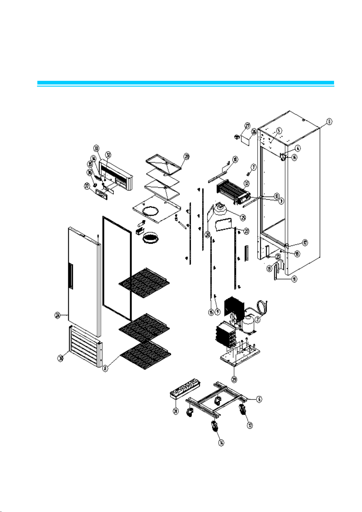
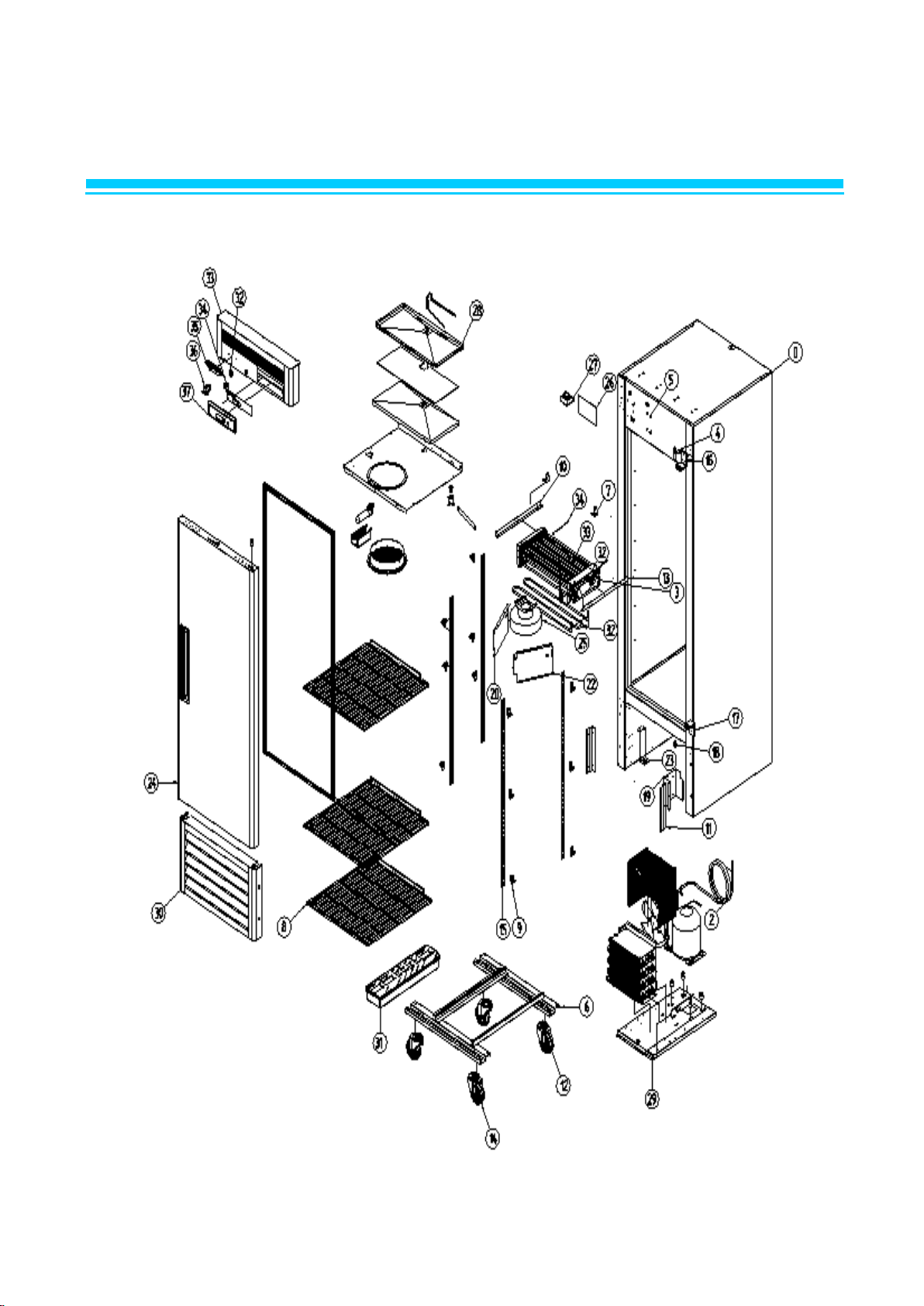
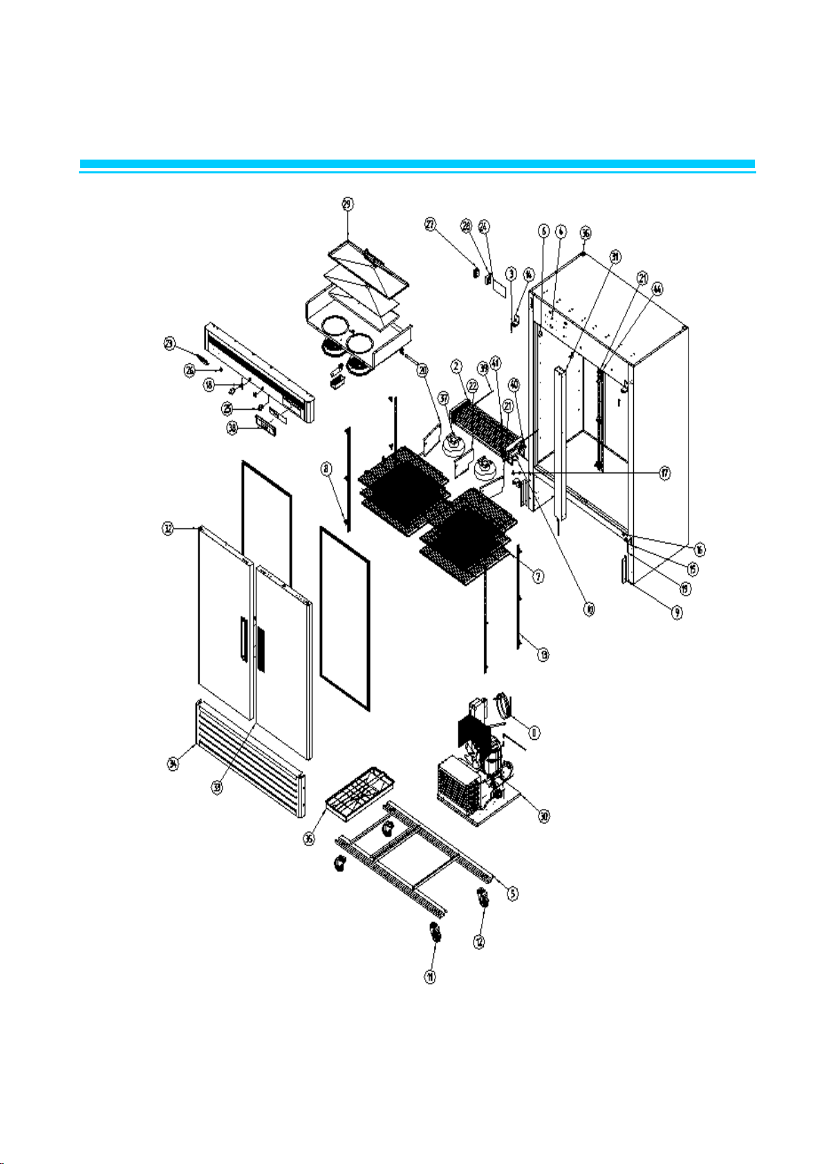
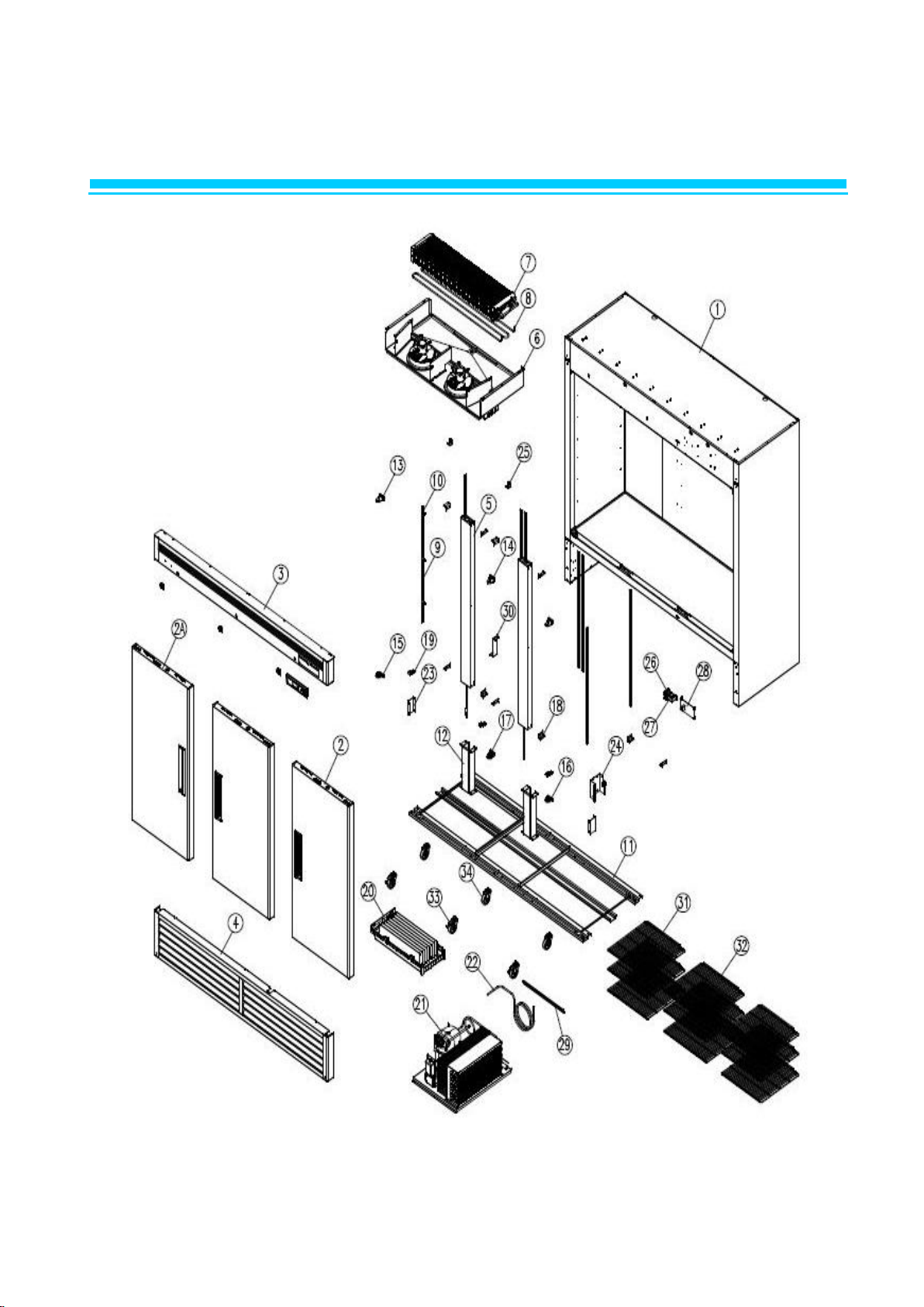
1. ASSEMBLY (BSR23)
Page 5
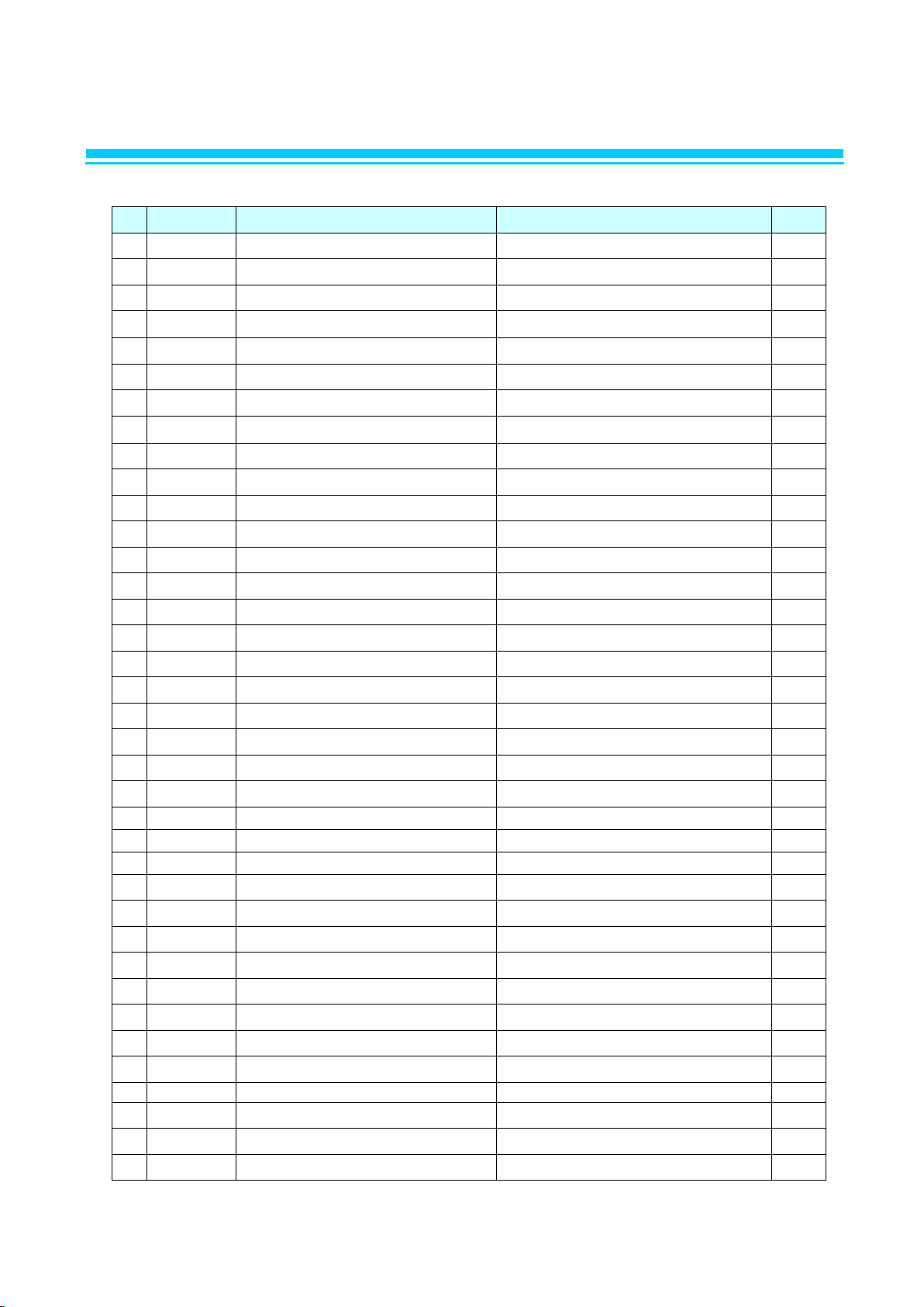
NO
CODE-No
Title
Subject
Q'TY
1
R827A-020
ASSY CABI URT
R23 1 2
R2103-445
COMPRESSOR PULL OUT
CU-PIPE. OD9.52*T0.6*1716
1
3
R8613-354
EVAPORATOR ASSY
AL
1
4
R858A-410
SHAFT TOP HINGE AS
SUM24L. ¢15*114
1
5
C3379-240
SUPPORT
SDSAA-9N
4
6
R3212-231
FRAME ASSY 23
WELDING 600LT
1
7
R3314-282
TOP FRAME B/K
GI. T1.0*30*59.6
2
8
R3233-200
SHELF 23
MSWR10. NSF
3
9
R3313-152
SHELF CLIP
POM. WHT
12
10
R3313-271
EVAPORATOR B/K LF
STS304-2B. T1.0*408*37.5
1
11
R315A-060
BRACKET GRILLE
GI. T1.0*110*102.5
2
12
R3323-230
CASTER 4"
4" MOVE
2
13
R3313-271
EVAP COVER B/K LF
STS304-2B. T1.0*408*37.5
1
14
R3323-240
CASTER 4"
4" STOP
2
15
R3373-630
SHELF STANDARD L
AL. T1.2*930
4
16
R828A-062
ASSY HINGE TOP RH
STS304 T=4.0
1
17
R828A-020
ASSY HINGE BOTTOM RH
STS304 T=4.0
1
18
R375A-030
STOPPER DOOR RH
POM (FW700S)
1
19
R3813-351
COVER CAPACITOR
GI. T0.8*255.2*135
1
20
R3853-110
EVAPORATOR AIR GUIDE LF
AL WHITE T0.5*162*247
1
22
R3853-090
EVAPORATOR AIR GUIDE RIGHT
AL WHITE T0.5*162*247
1
23
R3854-210
EVAPORATOR DRAIN HOSE GUIDE
GI. T1.0*225*60
1
24
R817A-340
DOOR ASSY 23
R23
1
25
R8329-060
EVAPORATOR FAN MOTOR ASSY
115V 60HZ
1
26
R7109-780
MAIN PCB (115. ℉)
115V. REF 2010 Energy Star
1
27
R7504-060
POWER TRANS
120V 60HZ. DT-1213
1
28
R8139-110
EVAPORATOR HOUSING ASSY
R23
1
29
R815A-010
ASSY UNIT
R23 1 30
R818A-310
ASSY GRILLE BOTTOM_23
23R/F
1
31
R8199-080
EVAPORATOR DRAIN WATER S ASSY
R/F23
1
32
R7204-070
POWER SWITCH
SL112A. 125V 15A
1
33
R818A-340
ASSY GRILL TOP_23
23F/R BLUE
1
34
R3734-030
DOOR LOCKING ASSY
ZDC. ZCR
1
35
R514A-031
MASCOT
T3.8*90*64
1
36
R7203-020
DOOR SWITCH
WHT. SP201R-9D
1
37
R832A-030
ASSY CONTROL BOARD 23
R/F 23
1
38
R7213-112
TEMP-DISPLAY SENSOR. REF
R23
1
1-1. PART LIST : BSR23
Page 6
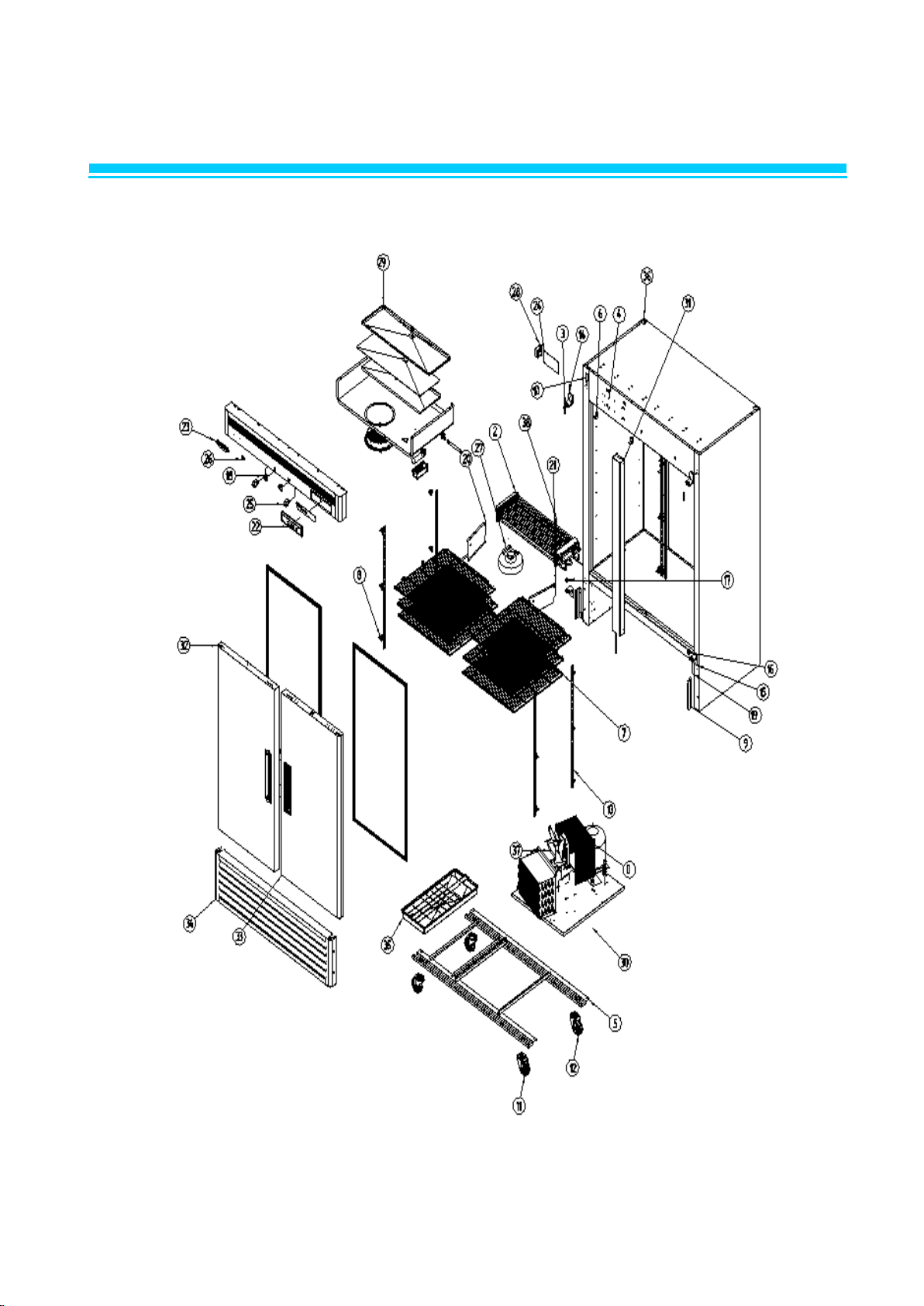
1. ASSEMBLY (BSF23)
Page 7
NO
CODE-No
Title
Subject
Q'TY
1
R827A-030
ASSY CABI FOAM
F23 1 2
R2103-445
COMPRESSOR PULL OUT
CU-PIPE. OD9.52*T0.6*1716
1 3 R2263-038
EVAPORATOR
CU+AL. 23F
1
4
R858A-410
SHAFT TOP HINGE AS
SUM24L Ø15*114
1
5
C3379-240
SUPPORT
SDSAA-9N
4 6 R3212-231
FRAME ASSY 23
WELDING 600LT
1 7 R3314-282
TOP FRAME B/K
GI. T1.0*30*59.6
2
8
R3233-200
SHELF 23
MSWR10. NSF
3
9
R3313-151
SHELF CLIP
POM. WHT
12
10
R3313-271
EVAPORATOR B/K LF
STS304-2B. T1.0*408*37.5
1
11
R315A-060
BRACKET GRILLE
GI. T1.0*110*102.5
2
12
R3323-230
CASTER 4"
4" MOVE
2
13
R3313-271
EVAP COVER B/K LF
STS304-2B. T1.0*408*37.5
1
14
R3323-240
CASTER 4"
4" STOP
2
15
R3373-630
SHELF STANDARD L
AL. T1.2*930
4
16
R828A-062
ASSY HINGE TOP RH
STS304 T=4.0
1
17
R828A-020
ASSY HINGE BOTTOM RH
STS304 T=4.0
1
18
R375A-030
STOPPER DOOR RH
POM (FW700S)
1
19
R3813-350
COVER CAPACITOR
GI. T0.8*255.2*135
1
20
R3853-110
EVAPORATOR AIR GUIDE LF
AL WHITE T0.5*162*247
1
22
R3853-090
EVAPORATOR AIR GUIDE RIGHT
AL WHITE T0.5*162*247
1
23
R3854-210
EVAPORATOR DRAIN HOSE GUIDE
GI. T1.0*225*60
1
24
R817A-340
DOOR ASSY 23
R23 1 25
R8329-060
EVAPORATOR FAN MOTOR ASSY
115V 60HZ
1
26
R7109-790
MAIN PCB (115. ℉)
115V. FRE 2010 Energy Star
1
27
R7504-060
POWER TRANS
120V 60HZ. DT-1213
1
28
R8139-090
EVAPORATOR HOUSING ASSY
F23 1 29
R815A-020
ASSY UNIT
F23 1 30
R818A-310
ASSY GRILLE BOTTOM_23
23R/F
1
31
R8199-080
EVAPORATOR DRAIN WATER S ASSY
R/F23
1
32
R7204-070
POWER SWITCH
SL112A. 125V 15A
1
33
R818A-340
ASSY GRILL TOP_23
23F/R BLUE
1
34
R3734-030
DOOR LOCKING ASSY
ZDC. ZCR
1
35
R514A-031
MASCOT
T3.8*90*64
1
36
R7203-020
DOOR SWITCH
WHT. SP201R-9D
1
37
R832A-030
ASSY CONTROL BOARD 23
R/F 23
1
38
R7303-402
DEFROST HEATER
F23 1 39
R7213-082
TEMP-THERMISTOR,FRE
F23 1 40
R7213-210
D-SENSOR
F23 1 41
R7253-052
EVAPORATOR THERMAL FUSE
F23
1
1-2. PART LIST : BSF23
Page 8
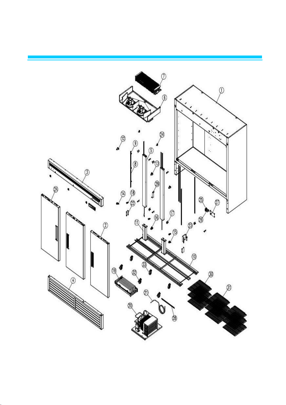
1. ASSEMBLY (BSR49)
Page 9
1-3. PART LIST : BSR49
NO
CODE-No
Title
Subject
Q'TY
1
R2103-942
COMPRESSOR PULL OUT
CU-PIPE. T0.7*OD9.52*1566
1 2 R8613-343
EVAPORATOR ASSY
R49 1 3
R858A-410
SHAFT TOP HINGE AS
SUM24L Ø15*114
2
4
C3379-240
SUPPORT
DSAA-9N
4 5 R3212-250
FRAME ASSY (49)
717.5*1408
1 6 R3314-282
TOP FRAME B/K
GI. T1.0*30*59.6
3 7 R3233-210
ASSY SHELF -49
MSWR10+PE
6 8 R3313-152
SHELF CLIP
POM. WHT
26
9
R315A-060
BRACKET GRILLE
GI. T1.0*110*102.5
2
10
R7213-112
RT-SENSOR
TH310H34GANR WHITE. L=200
1
11
R3323-230
CASTER 4"
4" MOVE
2
12
R3323-240
CASTER 4"
4" STOP
2
13
R3373-630
SHELF STANDARD L
AL. T1.2*930
6
14
R828A-062
ASSY HINGE TOP RH
STS304 T=4.0
1
15
R828A-020
ASSY HINGE BOTTOM RH
STS304 T=4.0
1
16
R375A-030
STOPPER DOOR RH
POM (FW700S)
1
17
R375A-040
STOPPER DOOR LF
POM (FW700S)
1
18
R3734-030
DOOR LOCKING ASSY
ZDC. ZCR
2
19
R3813-351
COVER CAPACITOR
GI. T0.8*255.2*135
1
20
R3853-210
EVAPORATOR AIR GUIDE LF
AL WHITE T0.5*161.8*269
1
21
R3853-120
EVAPORATOR AIR GUIDE RH
AL WHITE T0.5*161.8*269
1
22
R832A-040
ASSY CASE CONTROL BOARD 49
BLUE
1
23
R514A-031
MASCOT
T3.8*90*64
1
24
R7109-780
MAIN PCB (115V. ℉)
115V. REF 2010 Energy Star
1
25
R7203-020
DOOR SWITCH
WHT. SP201R-9D
2
26
R7204-070
POWER SWITCH
SL112A. 125V 15A
1
27
R8329-060
EVAPORATOR FAN MOTOR ASSY
UL. 115V 60HZ
1
28
R7504-060
POWER TRANS
120V 60HZ. DT-1213
1
29
R8139-100
EVAPORATOR HOUSING ASSY
R48
1
30
R815A-030
ASSY UNIT
R49. 115V. REF
1
31
R816A-280
ASSY CROSS BAR
R49
1
32
R817A-330
ASSY DOOR LF-BM
R/F49 BLUE
1
33
R817A-340
ASSY DOOR RH-BM
R/F49 BLUE
1
34
R818A-300
ASSY GRILLE BOTTOM_49
R/F49
1
35
R8199-070
EVAPORATOR DRAIN WATER-L ASSY
R/F49
1
36
R827A-040
CABI FOAM ASSY 49
R49
1
37
R8329-070
CONDENSER FAN MOTOR ASSY
115V 60HZ
1
38
R7213-112
TEMP-DISPLAY SENSOR. REF
TH310H34GANR WHITE. L=200
1
39
R828A-052
ASSY HINGE TOP LF
STS304 T=4.0
1
40
R828A-030
ASSY HINGE BOTTOM LF
STS304 T=4.0
1
Page 10
1. ASSEMBLY (BSF49)
Page 11
1-4. PART LIST : BSF49
NO
CODE-No
Title
Subject
Q'TY
1
R2113-580
COMPRESSOR PULL OUT. A
CU-PIPE. T0.7*OD9.52*1900
1
2
R2263-047
EVAPORATOR
F49 1 3
R858A-410
SHAFT TOP HINGE AS
SUM24L Ø15*114
2 4 C3379-240
SUPPORT
DSAA-9N
4 5 R3212-381
FRAME ASSY 49F
717.5*1408
1 6 R3314-282
TOP FRAME B/K
GI. T1.0*30*59.6
3 7 R3233-210
ASSY SHELF 49
MSWR10+PE
6 8 R3313-152
SHELF CLIP
POM. WHT
26 9 R315A-060
BRACKET GRILLE
GI. T1.0*110*102.5
2
10
R7303-412
DEFROST HEATER
UL 115V 600W
1
11
R3323-230
CASTER 4"
4" MOVE
2
12
R3323-240
CASTER 4"
4" STOP
2
13
R3373-630
SHELF STANDARD L
AL. T1.2*930
6
14
R828A-062
ASSY HINGE TOP RH
STS304 T=4.0
1
15
R828A-020
ASSY HINGE BOTTOM RH
STS304 T=4.0
1
16
R375A-030
STOPPER DOOR RH
POM (FW700S)
1
17
R375A-040
STOPPER DOOR LF
POM (FW700S)
1
18
R3734-030
DOOR LOCKING ASSY
ZDC. ZCR
2
19
R3813-351
COVER CAPACITOR
GI. T0.8*255.2*135
1
20
R3853-110
EVAPORATOR AIR GUIDE LF
AL WHITE T0.5*161.8*269
1
21
R3853-090
EVAPORATOR AIR GUIDE RH
AL WHITE T0.5*161.8*269
1
22
R3853-100
EVAPORATOR AIR GUIDE MID
AL WHITE. T0.5*161.8*243
1
23
R514A-031
MASCOT
T3.8*90*64
1
24
R7109-790
MAIN PCB (115. ℉)
115V. FRE 2010 Energy Star
1
25
R7203-020
DOOR SWITCH
WHT. SP201R-9D
2
26
R7204-070
POWER SWITCH
SL112A. 125V 15A
1
27
R7253-080
POWER RELAY
115V
1
28
R7504-060
POWER TRANS
120V 60HZ. DT-1213
1
29
R8139-080
EVAPORATOR HOUSING ASSY
F49
1
30
R8159-940
ASSY UNIT
F49. 115V. FRE
1
31
R816A-290
ASSY CROSS BAR
F49 1 32
R817A-330
ASSY DOOR LF-BM
R/F49 BLUE
1
33
R817A-340
ASSY DOOR RH-BM
R/F49 BLUE
1
34
R818A-300
ASSY GRILLE BOTTOM_49
R/F49
1
35
R8199-070
EVAPORATOR DRAIN WATER-L ASSY
R/F49
1
36
R827A-050
CABI FOAM ASSY 49
F49 1 37
R8329-060
EVAPORATOR FAN MOTOR ASSY
115V 60HZ
2
38
R832A-040
ASSY CASE CONTROL BOARD 49
BLUE
1
39
R7213-210
D-SENSOR
F23 1 40
R7253-052
EVAPORATOR THERMAL FUSE
F23 1 41
R7213-082
TEMP-THERMISTOR. FRE
F23 1 42
R828A-052
ASSY HINGE TOP LF
STS304 T=4.0
1
43
R828A-030
ASSY HINGE BOTTOM LF
STS304 T=4.0
1
Page 12
1. ASSEMBLY (BSR72)
Page 13
1-5. PART LIST : BSR72
NO
CODE-No
Title
Subject
Q'TY
1
R814A-040
ASSY CABI PRE B72R
-
1
2
R817A-140
ASSY DOOR RH BM
- 2 2A
R817A-130
ASSY DOOR LF BM
- 1 3
R858A-560
TOP GRILLE AS B72
- 1 4
R858A-400
BOTTOM GRILLE AS
- 1 5
R816A-210
ASSY CROSS BAR(BM F)
- 2 6
R813A-050
ASSY EVA COVER B72R
- 1 7
R840A-020
ASSY EVA B72R
AL 1 8
R3373-630
SHELF STANDARD L
T1.2*930 ㎜
8 9 R835A-010
ASSY SHELF CLIP
POM. WHT
36
10
R337A-020
FRAME AS B72
PO. T=2.3 707.7*2057
1
11
R376A-020
SUPPORTER FRAME
GI T2.3 395.3*237.4
4
12
R828A-052
ASSY HINGE TOP LF
-
1
13
R828A-062
ASSY HINGE TOP RH
- 2 14
R828A-030
ASSY HINGE BOTTOM LF
- 1 15
R828A-020
ASSY HINGE BOTTOM RH
- 1 16
R828A-040
ASSY HINGE BOTTOM MID
- 1 17
R325A-030
COVER CORNER
ABS(GP35 BASF) 28.5*28.5*53
8
18
R3314-601
U-COVER BRACKET A
EGI 1.2T*81.61*20
3
19
R858A-530
VAPORI AS
-
1
20
R815A-240
ASSY UNIT B72F
- 1 21
R319A-030
PIPE PULL OUT B72
Φ 9.52 * 1914L
1
22
R315A-060
BRACKET GRILLE
GI T=1.0*110*102.5
2
23
R3813-351
COVER CAPACITOR
SGCC-M, T0.8*135*255.2
1
24
R3314-282
TOP FRAME BRACKET
GI, T1.0*30*59.6
3
25
R7253-040
POWER RELAY
G7L-2A-TUB (30281H0310)
1
26
R7504-060
POWER TRANS
120V/60HZ, DT-1213
1
27
R7109-790
MAIN PCB (115. ℉)
115V. FRE 2010 Energy Star
1
28
R315A-100
BRACKET COMP BASE
T=1.0, 473*50.5
1
29
R3854-210
EVAPORATOR DRAIN HOSE GUIDE
GI T1.0X225X60
1
30
R3233-210
ASSY SHELF 49
MSWR10+PE
6
31
R834A-100
ASSY SHELF 72
MSWR10+PE
3
32
R3323-240
CASTER 4"
4" STOP
3
33
R3323-230
CASTER 4"
4" MOVE
3
Page 14
1. ASSEMBLY (BSF72)
Page 15
1-6. PART LIST : BSF72
NO
CODE-No
Title
Subject
Q'TY
1
R814A-040
ASSY CABI PRE B72R
-
1
2
R817A-140
ASSY DOOR RH BM
- 2 2A
R817A-130
ASSY DOOR LF BM
- 1 3
R858A-560
TOP GRILLE AS B72
- 1 4
R858A-400
BOTTOM GRILLE AS
- 1 5
R816A-210
ASSY CROSS BAR(BM F)
- 2 6
R813A-050
ASSY EVA COVER B72R
- 1 7
R840A-030
ASSY EVA B72F
CU 1 8
R7313-440
DEFROST HEATER 60
115V 900W 14.7Ω
1 9 R3373-630
SHELF STANDARD L
T1.2*930 ㎜
8
10
R835A-010
ASSY SHELF CLIP
POM. WHT
36
11
R337A-020
FRAME AS B72
PO. T=2.3 707.7*2057
1
12
R376A-020
SUPPORTER FRAME
GI T2.3 395.3*237.4
4
13
R828A-052
ASSY HINGE TOP LF
- 1 14
R828A-062
ASSY HINGE TOP RH
- 2 15
R828A-030
ASSY HINGE BOTTOM LF
- 1 16
R828A-020
ASSY HINGE BOTTOM RH
- 1 17
R828A-040
ASSY HINGE BOTTOM MID
- 1 18
R325A-030
COVER CORNER
ABS(GP35 BASF) 28.5*28.5*53
8
19
R3314-601
U-COVER BRACKET A
EGI 1.2T*81.61*20
3
20
R858A-530
VAPORI AS
- 1 21
R815A-250
ASSY UNIT B72F
- 1 22
R319A-030
PIPE PULL OUT B72
Φ 9.52 * 1914L
1
23
R315A-060
BRACKET GRILLE
GI T=1.0*110*102.5
2
24
R3813-351
COVER CAPACITOR
SGCC-M, T0.8*135*255.2
1
25
R3314-282
TOP FRAME BRACKET
GI, T1.0*30*59.6
3
26
R7253-040
POWER RELAY
G7L-2A-TUB (30281H0310)
1
27
R7504-060
POWER TRANS
120V/60HZ, DT-1213
1
28
R7109-790
MAIN PCB (115. ℉)
115V. FRE 2010 Energy Star
1
29
R315A-100
BRACKET COMP BASE
T=1.0, 473*50.5
1
30
R3854-210
EVAPORATOR DRAIN HOSE GUIDE
GI T1.0X225X60
1
31
R3233-210
ASSY SHELF 49
MSWR10+PE
6
32
R834A-100
ASSY SHELF 72
MSWR10+PE
3
33
R3323-240
CASTER 4"
4" STOP
3
34
R3323-230
CASTER 4"
4" MOVE
3
Page 16
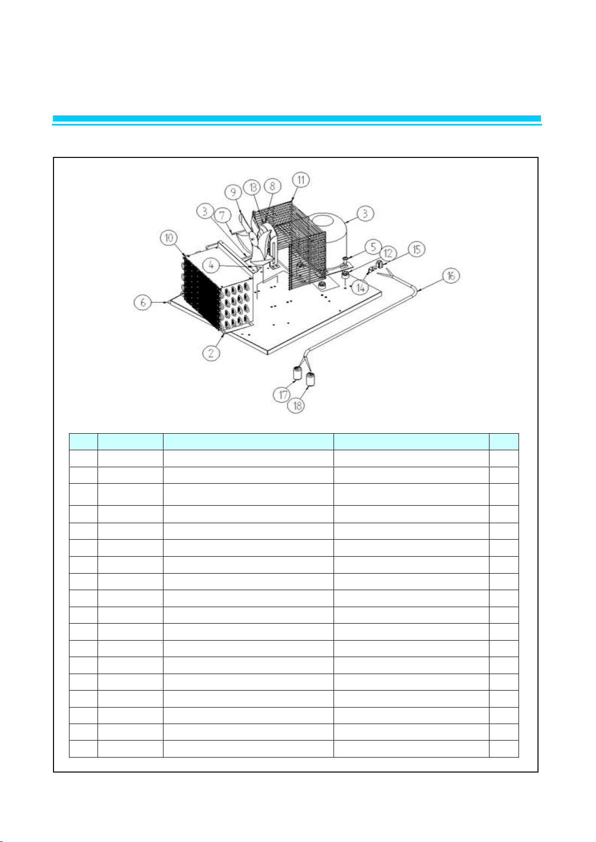
2. PARTS
NO.
CODE-No
Title
Subject
Q'TY
1
R7439-110
COMPRESSOR
SK1A1C-L2W
1
2
R2202-031
CONDENSER COIL
SWST. ¢4.76*13190
1
3
R2114-350
DICHARGE PIPE
CU. T0.6*¢6.35*130
1
4
R2103-433
CONDENSER DRYER PIPE
CU. ¢4.76*368
1
5
R2183-032
DRYER (R-134A. 36G)
36G
1
6
R3202-385
BASE COMP
GI. T1.2*359*605
1 7 R3313-260
CONDENSER FAN MOTOR BRACKET
GI
1
8
R3723-070
CONDENSER FAN BLADE
AL. ¢225. 9" CCW
1
9
R3813-121
CONDENSER COIL COVER
GI. T0.8*265*187
1
10
R3813-150
CONDENSER FAN COVER WIRE
MSWR10. ¢2.5
1
11
R3884-060
GROMMET
NY-6 . ¢12.6*25
4
12
R7423-311
CONDENSER FAN MOTOR
115V 60HZ. DAI-8204DYCA. CW
1
13
R7523-053
HARNESS RELAY B
UL
1
14
R7519-070
O.L.P
4TM795TFB-53
1
15
R7539-190
POSISTOR
SO68-CSR
1
16
R7549-260
RUNNING CAPACITOR
350VAC 50/60HZ 15 ㎌
1
17
R7549-270
CAPACITOR STARTING
160VAC 145 ㎌
1
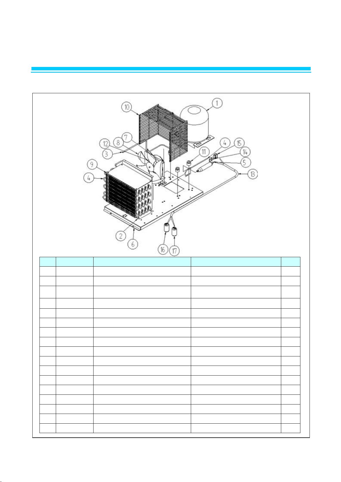
2-1. UNIT ASSY (BSR23)
Page 17
2. PARTS
NO.
CODE-No
Title
Subject
Q'TY
1
R7439-110
COMPRESSOR
SK1A1C-L2W
1
2
R2202-031
CONDENSER COIL
SWST. ¢4.76*13190
1
3
R2114-350
DICHARGE PIPE
CU. T0.6*¢6.35*130
1
4
R2103-433
CONDENSER DRYER PIPE
CU. ¢4.76*368
1
5
R2183-032
DRYER (R-134A. 36G)
36G
1
6
R3202-385
BASE COMP
GI. T1.2*359*605
1
7
R3313-260
CONDENSER FAN MOTOR BRACKET
GI
1
8
R3723-070
CONDENSER FAN BLADE
AL. ¢225. 9" CCW
1
9
R3813-121
CONDENSER COIL COVER
GI. T0.8*265*187
1
10
R3813-150
CONDENSER FAN COVER WIRE
MSWR10. ¢2.5
1
11
R3884-060
GROMMET
NY-6 . ¢12.6*25
4
12
R7423-311
CONDENSER FAN MOTOR
115V 60HZ. DAI-8204DYCA. CW
1
13
R7483-023
HARNESS RELAY A
UL
1
14
R7519-070
O.L.P
4TM795TFB-53
1
15
R7539-190
POSISTOR
SO68-CSR
1
16
R7549-260
RUNNING CAPACITOR
350VAC 50/60HZ 15 ㎌
1
17
R7549-270
CAPACITOR STARTING
160VAC 145 ㎌
1
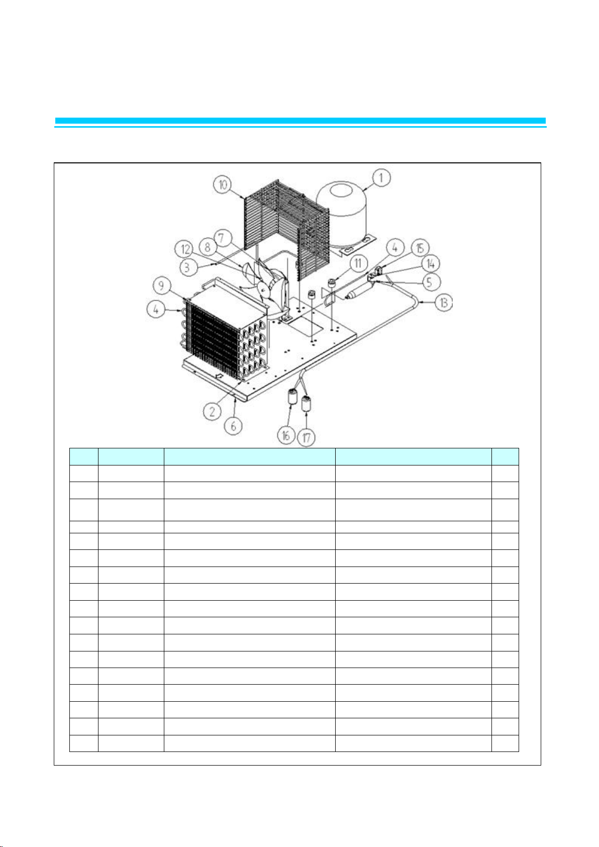
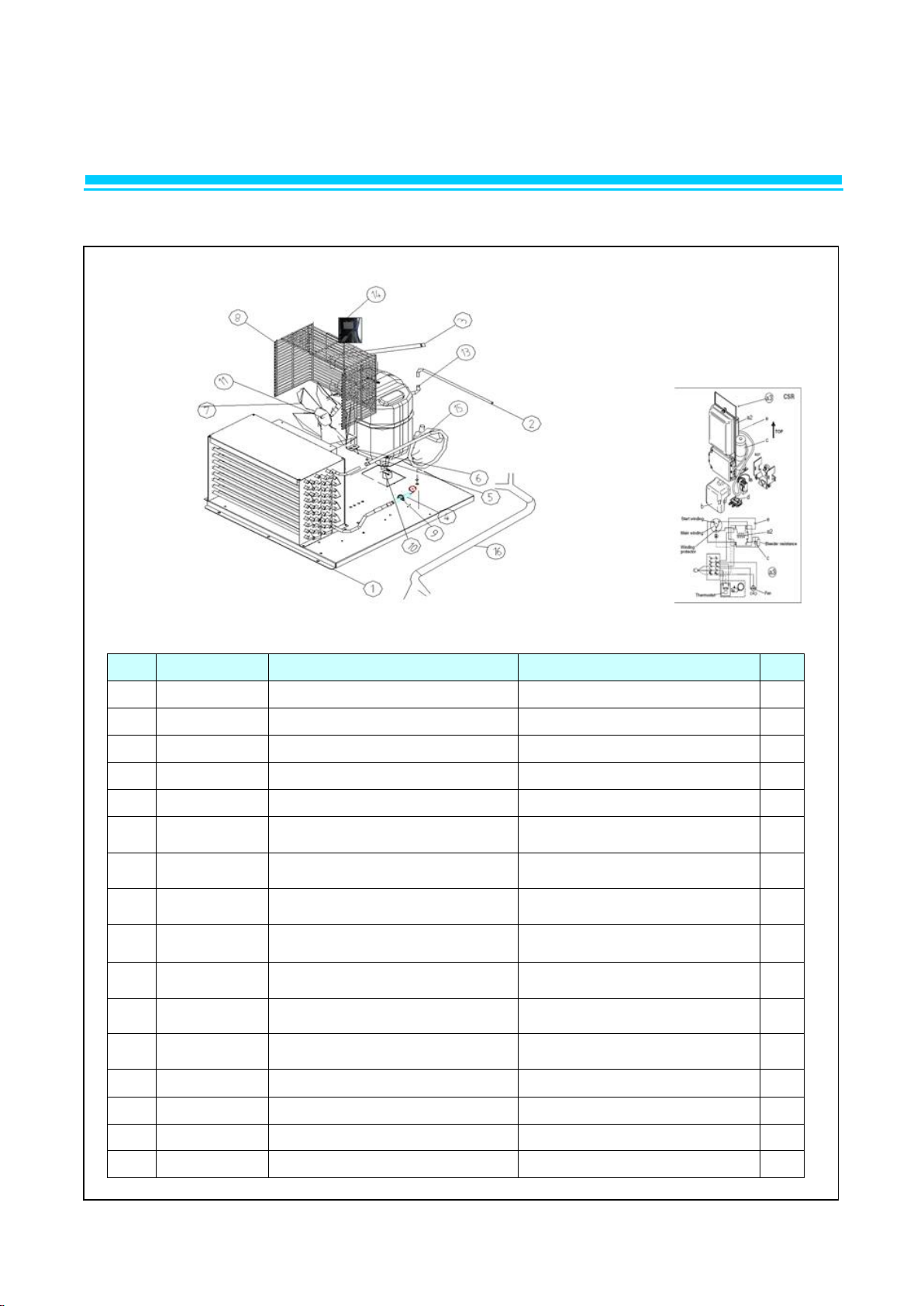
2-1. UNIT ASSY (BSF23)
Page 18
2. PARTS
NO.
CODE-No
Title
Subject
Q'TY
1
R7439-110
COMPRESSOR
SK1A1C-L2W
1 2 R2202-031
CONDENSER COIL
SWST. ¢4.76*13190
1
3
R2109-670
CONDENSER DRYER PIPE
CU. ¢4.76*321
1
4
R2183-032
DRYER (R-134A. 36G)
36G
1
5
R3004-270
COMPRESSOR BOLT
STS. M6*30Y. ¢10
4
6
R3202-421
BASE COMP
GI. T1.2*645*574
1 7 R2103-930
CONDENSER PIPE
T0.7*OD4.86*654. CU
1
8
R3313-260
CONDENSER FAN MOTOR BRACKET
GI
1
9
R3723-070
CONDENSER FAN BLADE
AL. ¢225. 9" CCW
1
10
R3813-121
CONDENSER COIL COVER
GI. T0.8*265*187
1
11
R3813-150
CONDENSER FAN COVER WIRE
MSWR10. ¢2.5
1
12
R3884-030
GROMMET COMP
NR-RUBBER. BLK
4
13
R7423-311
CONDENSER FAN MOTOR
115V 60HZ. DAI-8204DYCA. CW
1
14
R7483-033
HARNESS RELAY D
UL
1
15
R7519-070
O.L.P
4TM795TFB-53
1
16
R7539-190
POSISTOR
SO68-CSR
1
17
R7549-260
RUNNING CAPACITOR
350VAC 50/60HZ 15 ㎌
1
18
R7549-270
CAPACITOR STARTING
160VAC 145 ㎌
1
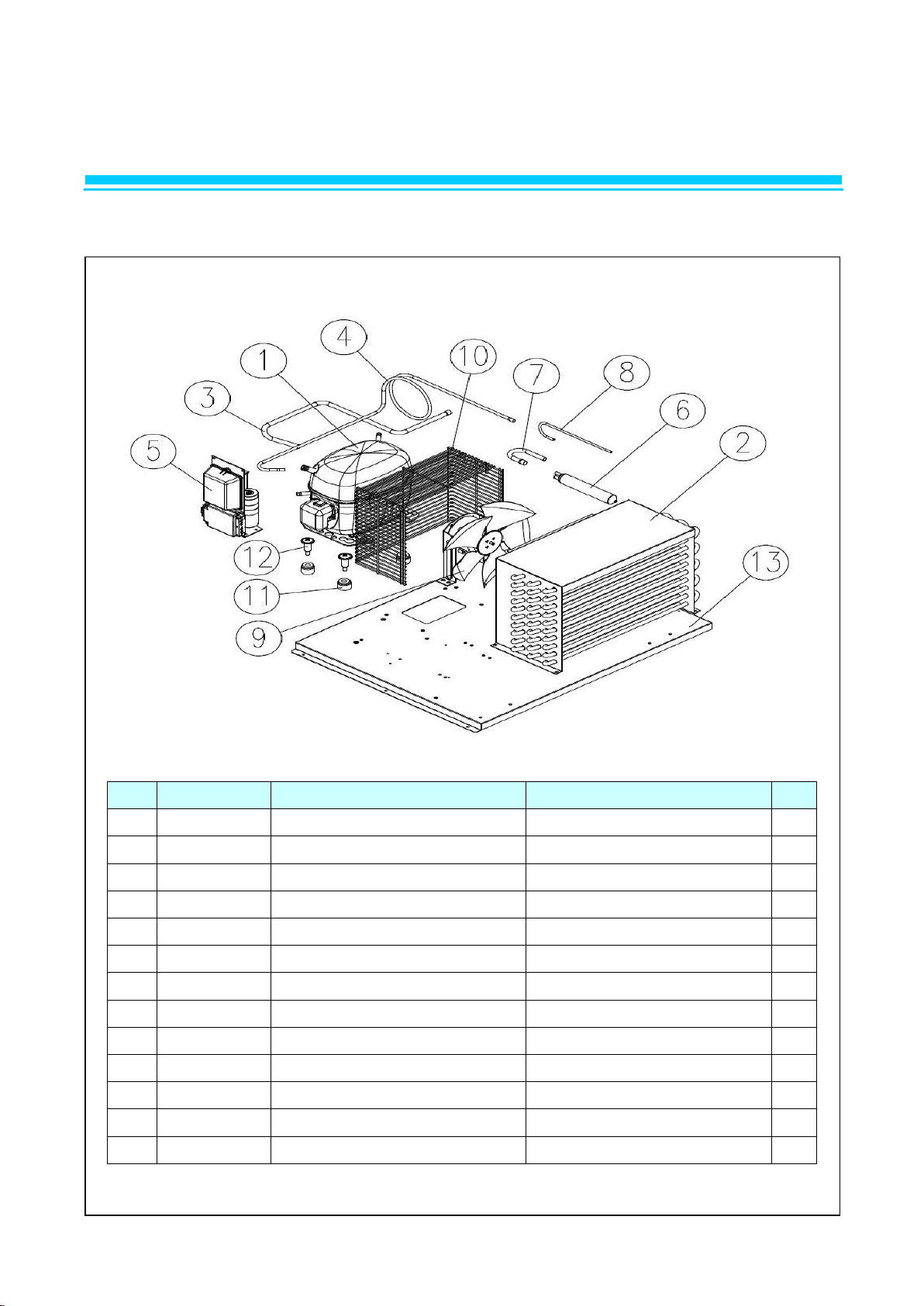
2-1. UNIT ASSY (BSR49)
Page 19
2. PARTS
NO.
CODE-No
Title
Subject
Q'TY
1
R3202-397
BASE COMP
GI. T1.2*555*614
1 2 R2104-460
COMPRESSOR CHARGING PIPE
CU-PIPE. OD6.35*T0.7*200
1 3 R2113-580
COMPRESSOR PULL OUT
1 4
R2183-200
DRIER ASSY
UL
1
5
R3004-270
COMPRESSOR BOLT
STS. M6*30Y. ¢10
4
6
R3313-260
CONDENSER FAN MOTOR
BRACKET
GI
1
7
R3723-070
CONDENSER FAN BLADE
AL. ¢225. 9" CCW
1
8
R3813-160
CONDENSER FAN COVER WIRE
MSWR. ¢2.5
1
9
R3834-130
CABLE CLAMP
DA-18N NYLON-66
1
10
R3884-030
GROMMET COMP
NR-RUBBER. BLK
4
11
R7423-311
CONDENSER FAN MOTOR
UL
1
12
R7439-600
COMPRESSOR
SC18CLX2
1
13
R7549-280
STARTING CAPACITOR
125~165V 410 ㎌
1
14
R7549-290
RUNNING CAPACITOR
280V 23.5 ㎌
1
15
R2103-474
CONDENSER CONNECTOR
UL. OD9.52*T0.7*795
1
16
R7483-014
HARNESS RELAY C
UL
1
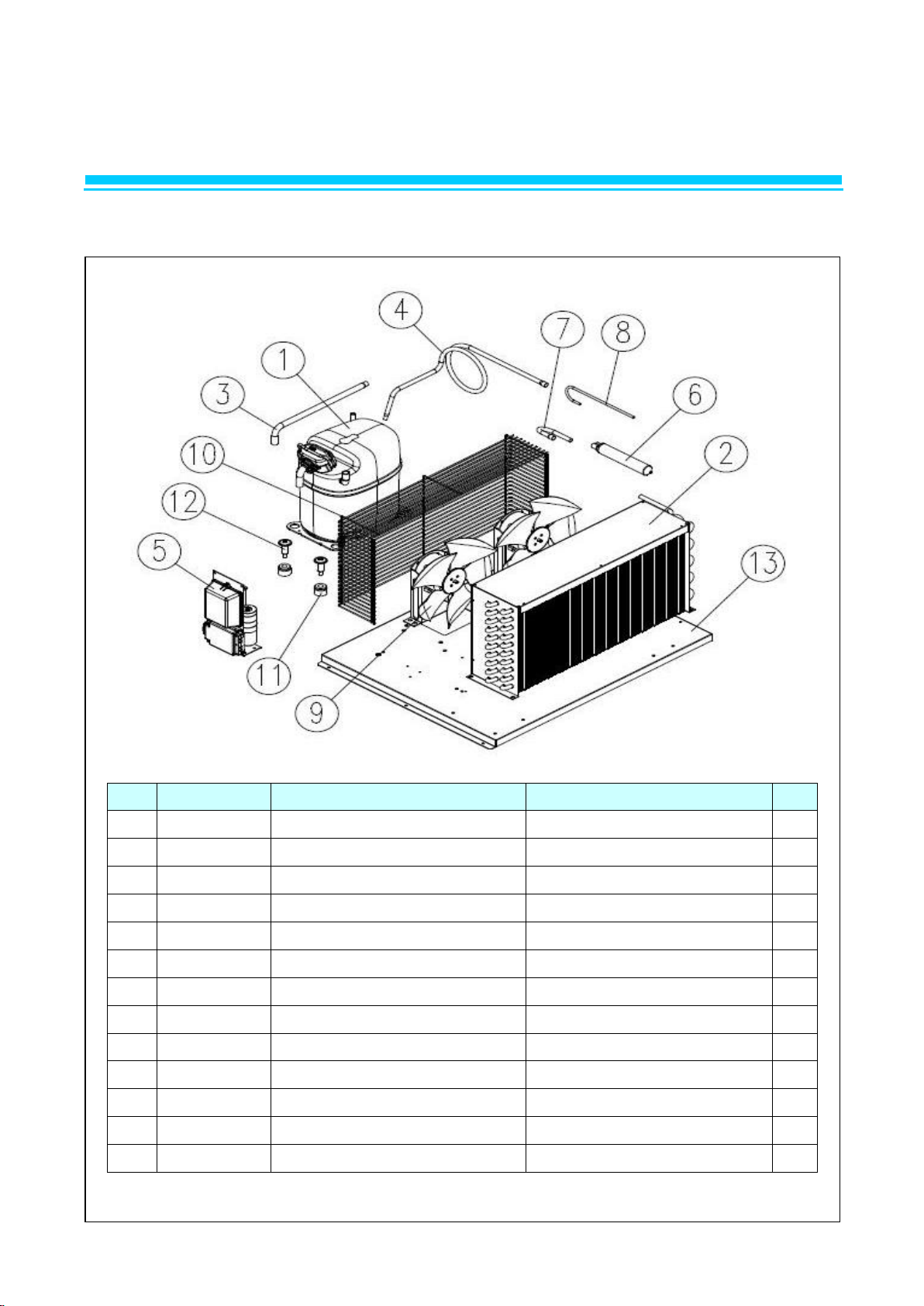
2-1. UNIT ASSY (BSF49)
Page 20
2. PARTS
NO.
CODE-No
Title
Subject
Q'TY 1 R714A-010
COMPRESSOR
SC18G
1 2 R2272-013
CONDENSER COIL
370*184
1 3 R319A-020
PIPE PULL OUT B
Φ 9.52
1 4 R2113-570
DISCHARGE CONNECTOR
CU PIPE. ¢6.35*T0.7*1215
1 5 R7539-200
POSISTOR
J531Q35E330M3852. 33Ω. 385V
1 6 R2183-200
DRYER ASSY
¢25.73*0.8T*169. CU-PIPE
1 7 R319A-010
PIPE COND OUTLET
C1220T
1 8 R2104-981
PIPE DRYER
- 1 9
R8329-070
CONDENSER FAN MOTOR ASSY
115V 60 ㎐
1
10
R3813-791
FAN COVER WIRE
MSWR. ¢2.5
1
11
R3884-030
GROMMET COMP
NR-RUBBER,BLK
4
12
R3004-270
COMPRESSOR BOLT
M6*30Y ¢10
4
13
R312A-010
BASE COMP
GI T=1.2 700*556.2
1
2-1. UNIT ASSY (BSR72)
Page 21
2. PARTS
NO.
CODE-No
Title
Subject
Q'TY
1
R714A-020
COMPRESSOR
GS26CLX
1
2
R2272-030
CONDENSER COIL PIN
CU,545*270*140
1
3
R2114-330
COMPRESSOR PULL OUT, B
T0.7*12.7
1 4 R2113-570
DISCHARGE CONNECTOR
CU PIPE. ¢6.35*T0.7*1215
1
5
R7539-200
POSISTOR
J531Q35E330M3852. 33Ω. 385V
1
6
R2183-200
DRYER ASSY
¢25.73*0.8T*169. CU-PIPE
1
7
R319A-010
PIPE COND OUTLET
C1220T
1
8
R2104-981
PIPE DRYER
-
1
9
R8329-070
CONDENSER FAN MOTOR ASSY
115V 60 ㎐
2
10
R3813-770
FAN COVER WIRE-B
MSWR10, OD2.6
1
11
R3884-030
GROMMET COMP
NR-RUBBER,BLK
4
12
R3004-270
COMPRESSOR BOLT
M6*30Y ¢10
4
13
R312A-010
BASE COMP
GI T=1.2 700*556.2
1
2-1. UNIT ASSY (BSF72)
Page 22
2. PARTS
NO.
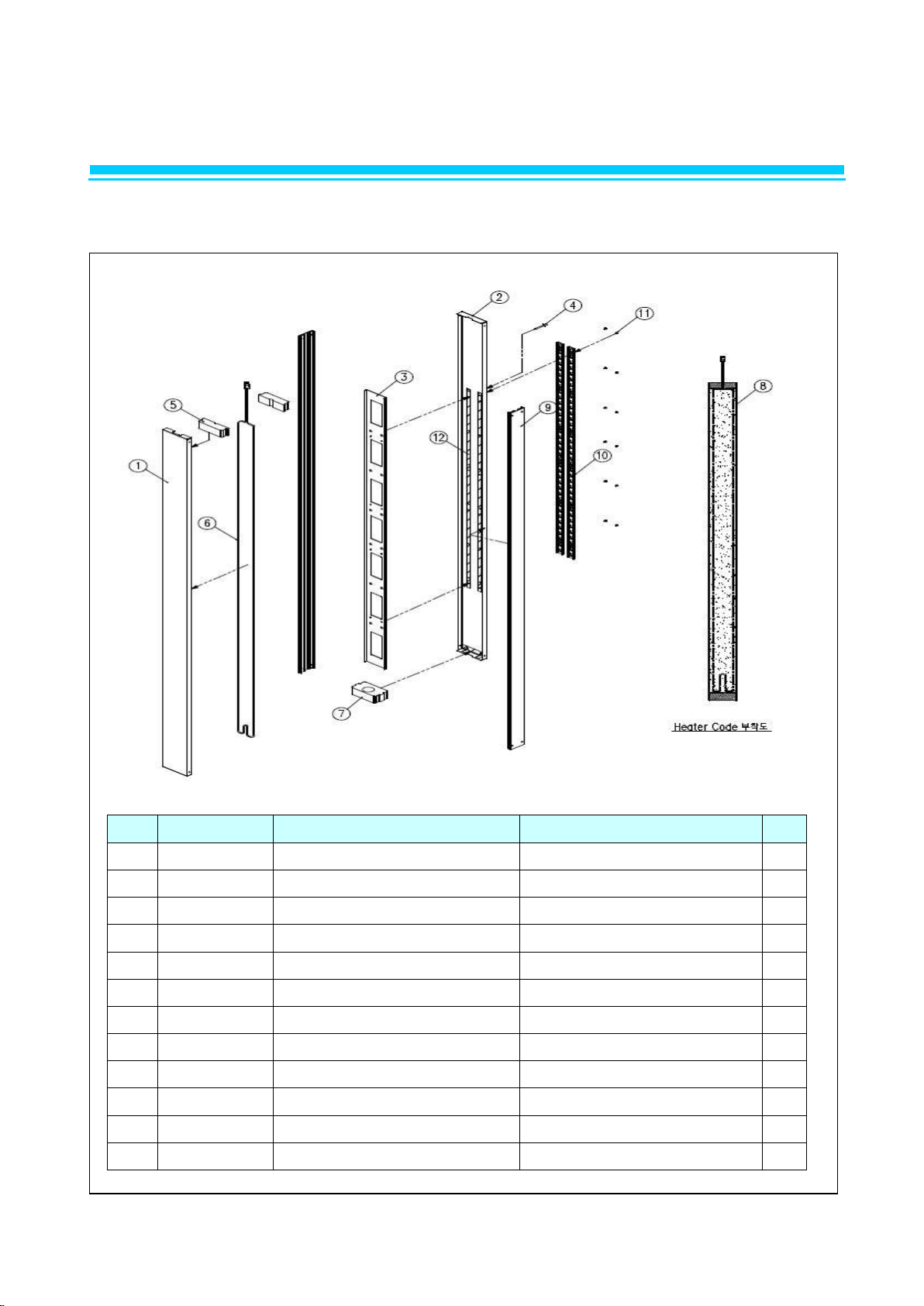
CODE-No
Title
Subject
Q'TY
1
R359A-380
Plate Cross Bar Front
STS443CT T=0.5 1345.2*118.2
1
2
R359A-390
Plate Cross Bar Rear
STS443CT T=0.5 1354.2*118.2
1 3 R365A-021
Reinf Cross Bar T72
GI T0.8*1180*103.6
1
4
R3069-010
Rivet Blind
Ø3.2
4
5
R320A-010
Cap End Top T72
EPS T30*110*24.5
2 6 R7303-125
Heater Cord Cross Bar
30w
1
7
R320A-020
Cap End Bottom T72
EPS T30*90*49
1
8
R1129-310
Tape Aluminium
W80
2.5M
9
R368A-240
SASH CROSS BM
ABS L=1315MM
2
10
R3373-630
Shelf Standard L
T1.2*930mm
2
11
R4213-030
Screw FH M4*16 직결
M4X16
12
12
R1129-010
Kraft Tape
W25
2.4
2-2. CROSS BAR ASSY (49R,72R)
Page 23
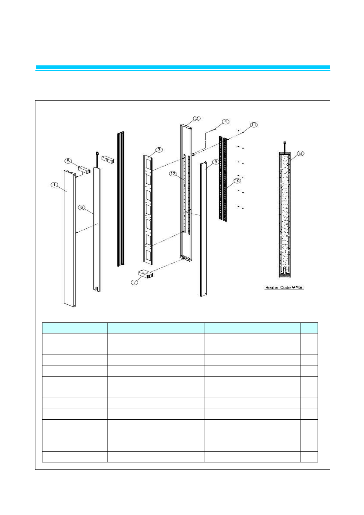
2. PARTS
NO.
CODE-No
Title
Subject
Q'TY 1 R359A-380
Plate Cross Bar Front
STS443CT T=0.5 1345.2*118.2
1 2 R359A-390
Plate Cross Bar Rear
STS443CT T=0.5 1354.2*118.2
1 3 R365A-021
Reinf Cross Bar T72
GI T0.8*1180*103.6
1 4 R3069-010
Rivet Blind
Ø3.2
4 5 R320A-010
Cap End Top T72
EPS T30*110*24.5
2 6 R7303-115
Heater Cord Cross Bar
38w
1 7 R320A-020
Cap End Bottom T72
EPS T30*90*49
1 8 R1129-310
Tape Aluminium
W80
2.5M
9
R368A-240
SASH CROSS BM
ABS L=1315MM
2
10
R3373-630
Shelf Standard L
T1.2*930mm
2
11
R4213-030
Screw FH M4*16 직결
M4X16
12
12
R1129-010
Kraft Tape
W25
2.4
2-2. CROSS BAR ASSY (49F,72F)
Page 24
2. PARTS
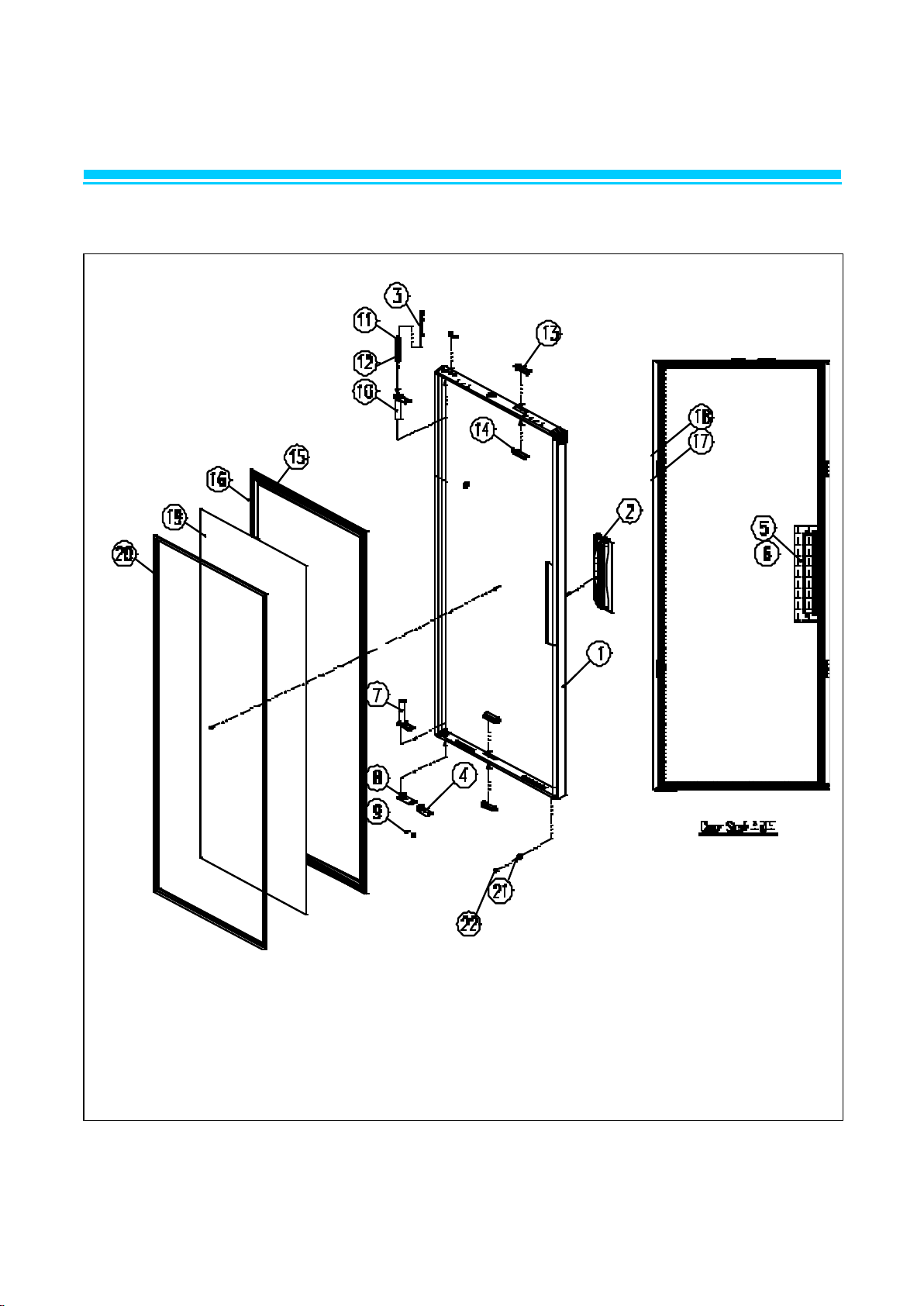
2-3. DOOR ASSY (BSR/F23, BSR/F49, BSR/F72)
Page 25

NO.
CODE-No
Title
Subject
Q'TY
1
R359A-410
PLATE DOOR BLUE
STS430-#4 T0.5*1514*823
1
2
R342A-011
HANDEL DOOR
PC-ABS (GN5201F)
1
3
R858A-410
SHAFT TOP HINGE AS
SUM24L Ø15*114
2
4
R375A-041
STOPPER DOOR LF
POM (700S)
1
5
R1129-140
COTTON TAPE (W50)
W50
1.5M
6
R1129-060
AL TAPE
W50
1.5M
7
R313A-011
BODY DOOR SPRING
ZNDC 97*70*26
1 8 R375A-031
STOPPER DOOR RH
POM (700S)
1
9 SCREW
FH5*15
4
10
R313A-011
BODY DOOR SPRING
ZNDC 97*70*26
1
11
R374A-020
SPRING DOOR RH
SW-C Ø2.3
1
12
R374A-010
SPRING DOOR LF
SW-C Ø2.3
1
13
R3932-360
CAP DOOR LOCK
ABS 69.8*21.8
2
14
R3932-380
BODY DOOR LOCK
ABS 78*60*10.3
2
15
R368A-050
SASH DOOR ST72
ABS L=643
2
16
R368A-260
SASH DOOR L BM
ABS L=1386
2
17
R1129-140
COTTON TAPE
W50
0.5M
18
R1129-160
TAPE TWO FACE
4.2M
19
R359A-400
PLATE DOOR REAR BM
STS443CT T0.4*1331*588
1
20
R338A-040
GASKET DOOR BM
난연 PVC 1353*610
1
21
R1254-051
DOOR RUBBER LEG
SILICON Ø16*12
2
22
R4213-030
SCREW
FH M4*16
2
Page 26
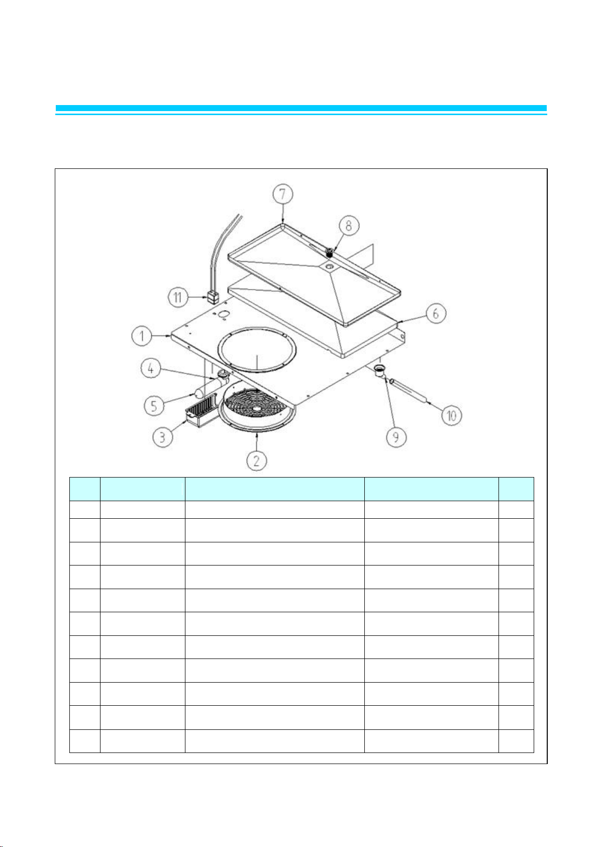
2. PARTS
NO.
CODE-No
Title
Subject
Q'TY
1
R3813-472
EVAPORATOR HOUSING
STS443CT. T0.5X575X558
1
2
R3812-141
EVAPORATOR FAN MOTMOR GUARD
HIPS (VH-1800EX). UL
1 3 R325A-041
LAMP COVER
MIPS(HIPS B-5676). WHT
1
4
R7393-021
LAMP SOCKET
250V 660W
1
5
R7394-010
LAMP BULB
25T10. 120V 25W
1
6
R1143-202
INSUL DRAIN 23
EPS. 17*530*256
1 7 R3743-051
EVAPORATOR DRAIN PAN SMALL
AL. T0.8
1 8 R3744-091
EVAPORATOR DRAIN ELBOW UPP
PP. WHT
1
9
R3744-101
EVAPORATOR DRAIN ELBOW LOW
PP. WHT
1
10
R2124-021
EVAPORATOR DRAIN HOSE A
SILICON. CLEAR. 16*12.
L=213
1
11
R7403-111
HARNESS LAMP, L
UL
1
2-4. EVAPORATOR HOUSING ASSY (BSR23)
Page 27

2. PARTS
NO.
CODE-No
Title
Subject
Q'TY 1 R3813-472
EVAPORATOR HOUSING
STS443CT. T0.5X575X558
1 2 R3812-141
EVAPORATOR FAN MOTMOR GUARD
HIPS (VH-1800EX). UL
1 3 R325A-041
LAMP COVER
MIPS(HIPS B-5676). WHT
1 4 R7393-021
LAMP SOCKET
250V 660W
1 5 R7394-010
LAMP BULB
25T10. 120V 25W
1 6 R1143-202
INSUL DRAIN 23
EPS. 17*530*256
1 7 R3743-051
EVAPORATOR DRAIN PAN SMALL
AL. T0.8
1 8 R3744-091
EVAPORATOR DRAIN ELBOW UPP
PP. WHT
1 9 R3744-101
EVAPORATOR DRAIN ELBOW LOW
PP. WHT
1
10
R7303-174
HEATER DRAIN PAN
115V 90W. UL
1
11
R2124-021
EVAPORATOR DRAIN HOSE A
SILICON. CLEAR. 16*12.L=213
1
12
R8393-030
HEATER CORD DRAIN HOSE ASSY
UL 10W
1
13
R7403-111
HARNESS LAMP, L
UL
1
2-4. EVAPORATOR HOUSING ASSY (BSF23)
Page 28

2. PARTS
NO.
CODE-No
Title
Subject
Q'TY 1 R3813-313
EVAP COVER
STS443CT. T0.8X1048X560
1 2 R1143-222
INSUL DRAIN R49
EPS. 17*622*256
1
3
R3743-041
EVAPORATOR DRAIN PAN MID
AL. T0.8
1
4
R3812-141
EVAPORATOR FAN MOTMOR GUARD
HIPS (VH-1800EX). UL
1
5
R3744-091
EVAPORATOR DRAIN ELBOW UPP
PP. WHT
1 6 R3744-101
EVAPORATOR DRAIN ELBOW LOW
PP. WHT
1
7
R7393-021
LAMP SOCKET
250V 660W
1 8 R7394-010
LAMP BULB
25T10. 120V 25W
1 9 R325A-041
LAMP COVER
MIPS(HIPS B-5676). WHT
1
12
R2124-021
EVAPORATOR DRAIN HOSE A
SILICON. CLEAR. 16*12.L=213
1
13
R7403-110
HARNESS LAMP, L
UL
1
2-4. EVAPORATOR HOUSING ASSY (BSR49)
Page 29

2. PARTS
NO.
CODE-No
Title
Subject
Q'TY
1
R3813-323
EVAP COVER
STS443CT. T0.5*1191X560
1
4
R3812-141
EVAPORATOR FAN MOTMOR GUARD
HIPS (VH-1800EX). UL
2 5 R7393-021
LAMP SOCKET
250V 660W
1
6
R7394-010
LAMP BULB
25T10. 120V 25W
1
7
R325A-041
LAMP COVER
MIPS(HIPS B-5676). WHT
1 8 R1143-212
INSUL DRAIN 49
EPS. 17*800*256
1
9
R3743-031
EVAPORATOR DRAIN PAN-LARGE F49
AL. T0.8
1
10
R3744-091
EVAPORATOR DRAIN ELBOW UPP
PP. WHT
1
11
R3744-101
EVAPORATOR DRAIN ELBOW LOW
PP. WHT
1
12
R8393-040
HEATER CORD DRAIN HOSE ASSY
UL 10W
1
13
R2124-021
EVAPORATOR DRAIN HOSE A
SILICON. CLEAR.
16*12.L=213
1
14
R7303-184
HEATER DRAIN PAN
115V 140W
1
15
R7403-111
HARNESS LAMP, L
UL
1
2-4. EVAPORATOR HOUSING ASSY (BSF49)
Page 30

2. PARTS
NO.
CODE-No
Title
Subject
Q'TY
1
R325A-070
COVER EVA B72R
STS443CT T0.5 1191*560
1 2 R3812-141
EVAPORATOR FAN MOTOR GUARD
HIPS (VH-1800EX)
2
3
R1143-212
EVAPORATOR DRAIN INSUL-L
T17*256*800, FOAM-PS
1
4
R3743-031
EVAPORATOR DRAIN PAN-LARGE
AL+COATING
1 5 R3314-350
BRACKET-DRAIN
STS304-2B, T0.5*25*57(P)
2 6 R3744-090
EVAPORATOR DRAIN ELBOW-UPP
PP WHITE(30209L0200)
1 7 R3744-100
EVAPORATOR DRAIN ELBOW-LOW
PP WHITE(30225L0100)
1 8 R2124-021
EVAPORATOR DRAIN HOSE A
SILICON. CLEAR. 16*12.L=213
1 9 R7393-021
LAMP SOCKET
L-125B 660W 20V
2
10
R7394-010
LAMP BULB
25T10. 120V 25W
2
11
R325A-041
LAMP COVER
MIPS(HIPS B-5676). WHT
2
12
R7403-111
HARNESS LAMP, L
UL
2
2-4. EVAPORATOR HOUSING ASSY (BSR72)
Page 31

2. PARTS
NO.
CODE-No
Title
Subject
Q'TY
1
R325A-060
COVER EVA B72F
STS443CT T=0.5*1405.8*559.7
1 2 R3812-141
EVAPORATOR FAN MOTOR GUARD
HIPS (VH-1800EX)
2 3 R1143-380
EVAPORATOR DRAIN INSUL-L
T17*256*800, FOAM-PS
1 4 R7313-431
HEATER DRAIN PAN
115V 90W
1 5 R3743-240
EVAP DRAIN PAN,L
AL,T0.8*1040*258,GST-72TF
1 6 R3314-350
BRACKET-DRAIN
STS304-2B, T0.5*25*57(P)
2 7 R3744-090
EVAPORATOR DRAIN ELBOW-UPP
PP WHITE(30209L0200)
1 8 R3744-100
EVAPORATOR DRAIN ELBOW-LOW
PP WHITE(30225L0100)
1 9 R2124-021
EVAPORATOR DRAIN HOSE A
SILICON. CLEAR. 16*12.L=213
1
10
R7313-490
HEATER CORD DRAIN HOSE
115V 10W
1
11
R7394-010
LAMP BULB
25T10. 120V 25W
2
12
R325A-041
LAMP COVER
MIPS(HIPS B-5676). WHT
2
13
R7393-021
LAMP SOCKET
L-125B 660W 20V
2
14
R7403-111
HARNESS LAMP, L
UL
2
2-4. EVAPORATOR HOUSING ASSY (BSF72)
Page 32

2. PARTS
NO.
CODE-No
Title
Subject
Q'TY
1
R359A-600
PLATE FRAME LOW
STS430-#4. T0.6*199*679
1 2 R3153-151
TOP FRAME MID PIECE-S
ABS. BLK. L=571
1
3
R359A-480
PLATE FRAME UPP
STS430-#4. T0.6*679*159.3
1 4 R359A-430
PLATE TOP GRILL SIDE
STS430-#4. T0.6*209*148
2
5
R514A-031
MASCOT
T3.8*90*64
1
6
R3734-030
DOOR LOCKING ASSY
ZDC. ZCR
1 7 R4142-122
CONTROL BOARD
(DIGITAL DISPLAY)
ABS. BLK. T2*242*72
1 8 R7113-210
DISPLAY PCB (℉)
88 SEGMENT. ℉
1
9
R7203-020
DOOR SWITCH
WHT. SP201R-9D
1
10
R7204-070
POWER SWITCH
SL112A. 125V 15A
1
11
R818A-340
ASSY GRILL TOP
23 BLUE
1
2-5. TOP FRAME ASSY (BSR/BSF23)
Page 33

2. PARTS
NO.
CODE-No
Title
Subject
Q'TY
1
R3153-141
TOP FRAME MID PIECE, L
ABS, BLK, L=1260
1
2
R359A-490
TOP FRAME UPP 49
STS430-#4. T0.6*1368*159.3
1
3
R359A-610
PLATE FRAME LOW_49
STS430-#4. T0.6*188*1368
1 4 R359A-430
PLATE TOP GRILL SIDE
STS430-#4. T0.6*209*148
2
5
R514A-031
MASCOT
T3.8*90*64
1 6 R3734-030
DOOR LOCKING ASSY
ZDC. ZCR
2
7
R4142-122
CONTROL BOARD (DIGITAL
DISPLAY)
ABS. BLK. T2*242*72
1 8 R7113-210
DISPLAY PCB (℉)
88 SEGMENT. ℉
1
9
R7204-070
POWER SWITCH
SL112A. 125V 15A
1
10
R7203-020
DOOR SWITCH
WHT. SP201R-9D
2
11
R818A-350
ASSY GRILL TOP
49 BLUE
1
2-5. TOP FRAME ASSY (BSR/BSF49)
Page 34

2. PARTS
NO.
CODE-No
Title
Subject
Q'TY
1
R359A-450
PLATE TOP GRILL UPPER
STS430 T=0.6*2057*158.9
1
2
R359A-440
PLATE TOP GRILL LOW
STS430 T=0.6*2057*194.9
1
3
R359A-430
PLATE TOP GRILL SIDE
STS430 T=0.6
2 4 R337A-010
FRAME TOP MID PIECE 72
ABS BLK L=1950
1 5 R7113-210
DISPLAY PCB (℉)
88 SEGMENT. ℉
1
6
R4142-122
CONTROL BOARD
ABS. BLK. T2*242*72
1 7 R7203-020
DOOR SWITCH
WHT. SP201R-9D
3
8
R3734-030
DOOR LOCKING ASSY
ZDC. ZCR
3
9
R7204-070
POWER SWITCH
SL112A. 125V 15A
1
10
R514A-031
MASCOT
T3.8*90*64
1
2-5. TOP FRAME ASSY (BSR/BSF72)
Page 35

2. PARTS
NO.
CODE-No
Title
Subject
Q'TY
1
R3743-060
TRAY-DRAIN WATER S
ABS, BLK
1 2 R3853-230
EVAPORATOR WICKING GUIDE
P.P. WHT. T2.0*569*40
1
3
R1154-010
DRAIN WICKING P/K
P.P. T2.5*99*103
7
4
C3009-100
SCREW THT2 4*6Y
THT2 46Y
4
NO.
CODE-No
Title
Subject
Q'TY
1
R3743-070
TRAY-DRAIN WATER L
ABS, BLK
1
2
R3853-240
EVAPORATOR WICKING GUIDE
P.P. WHT. T2.0*657*40
1
3
R1154-020
PAPER-KIT
P.P. T2.5*180*83
7 4 C3009-100
SCREW THT2 4*6Y
THT2 46Y
4
2-6. EVAPORATOR DRAIN WATER-S ASSY
MODEL : BSR23, BSF23
MODEL : BSR49, BSF49
Page 36

2. PARTS
NO.
CODE-No
Title
Subject
Q'TY
1
R3422-012
CASE VAPORI T49
ABS. 602.5*275*106.5
1 2 R110A-010
CLOTH WICKING DRAIN WATER
T=2.5*480*120
8 3 R3853-780
GUIDE WICKING
PP(WHITE). 1.5T*269*40
2
2-6. EVAPORATOR DRAIN WATER-S ASSY (BSR72, BSF72)
Page 37

3. WIRING DIAGRAM
3-1. 23Model
◇ BSR23
◇ BSF23
Page 38

3. WIRING DIAGRAM
3-2. 49Model
◇ BSR49
◇ BSF49
Page 39

3. WIRING DIAGRAM
3-2. 72Model
◇ BSR72
◇ BSF72
Page 40

4. PART DETAILS
4-1. TOP PANEL
◇ Display PCB
◇ Main PCB
Page 41

4. PART DETAILS
4-2. COMPRESSOR COMPARTMENT
◇ Condensing Unit
BSR49
BSF49
BSR23, BSF23
Page 42

4. PART DETAILS
4-3. DOOR
◇ Door Gasket
4-4. COOLING COMPARTMENT
◇ Evaporator Housing (Duct) (BSF49)
◇ Refrigerator Evaporator (BSF49)
Page 43

4. PART DETAILS
◇ Condensate Drain Pan
◇ Condenser Fan Motor Assembly
◇ Compressor Capacitor (Running & Starting Capacitor)
.
Page 44

4. PART DETAILS
BSF49
BSF23
◇ Evaporator Housing (Duct) (BSR23, BSF23)
◇ Coil Evaporator (BSF23)
◇ Evaporator Defrost Heater (BSF23, BSF49)
Page 45

5. MAIN COMPONENTS
MODEL
BSR23
BSF23
BSR49
S49F
Refrigerant
R-134a
R-134a
R-134a
R-404a
Voltage
115V
115V
115V
115V
Comp.
Model
SK1A1C-L2W
SK1A1C-L2W
SK1A1C-L2W
SC18CLX2
Part
code
(DY)
R7439-110
R7439-110
R7439-110
R7439-600
Image
MODEL
BSR23, BSF23
S49R
S49F
Voltage - 115V/60Hz
Relay Model - G7L-2A-TUB
Part
code
(DY)
-
R7253-040
Image
MODEL
BSR23
BSF23
BSR49
BSF49
Spec
160VAC
145 ㎌
160VAC
145 ㎌
160VAC
145 ㎌
125~165VAC
410 ㎌
Part
code
(DY)
R7549-270
R7549-270
R7549-270
R7549-280
Image
Assy
117U5043
5-1.COMPRESSOR
5-2.POWER-RELAY(COMP. RELAY)
5-3. STARTING CAPACITOR
Page 46

5-4. RUNNING CAPACITOR
MODEL
BSR23
BSF23
BSR49
BSF49
Spec
350VAC
15 ㎌
350VAC
15 ㎌
350VAC
15 ㎌
280VAC
23.5 ㎌
Part
code
(DY)
R3153-341
R3153-341
R3153-341
R7549-290
Image
Assy
117-7114
MODEL
BSR23
BSR49
BSF23
BSF49
Refrigerant
R-134a
R-404a
Spec
36GR
24G
Part
code
(DY)
R2183-032
R2183-200
Image
MODEL
BSR23
BSR49
BSF23
BSF49
Spec
4.76*13190
CU.OD9.52
Part
code
(DY)
R2202-031
R2272-013
Image
MODEL
BSR23
BSR49
BSF23
BSF49
Spec
AL. ¢225. 9" CCW
Part
code
(DY)
R3723-070
Image
5-5.CONDENSER DRYER
5-6.CONDENSER COIL
5-7. CONDENSER FAN BLADE
Page 47

5-8. CONDENSER FAN MOTOR
MODEL
BSR23
BSR49
BSF23
BSF49
Voltage
115V/60Hz
Motor Model
DAI-8204DYCA
Part
code
(DY)
R7423-311
Image
MODEL
BSR23
BSR49
BSF23
BSF49
Spec
SBHGI. T2.0*164
Part
code
(DY)
R3313-260
Image
MODEL
BSR23
BSR49
BSF23
BSF49
Voltage
115V/60Hz
Motor Model
DAI-8204DYCA-1
Part
code
(DY)
R7423-301
Image
5-9. CONDENSER FAN MOTOR BRACKET
5-10.EVAPORATOR FAN MOTOR
Page 48

5-11.EVAPORATOR COIL
MODEL
BSR23
BSR49
BSF23G
BSF49
Spec
CU+AL
CU+AL
CU+AL
CU+AL
Part
code
(DY)
R8613-354
R8613-343
R2263-038
R2263-047
Image
MODEL
BSR23
BSR49
BSF23
BSF49
Voltage
115V/60Hz
Spec
-
445W
600W
Part
code
(DY) - R7303-402
R7303-412
Image
MODEL
BSR23
BSR49
BSF23
BSF49
Spec
8". C.C.W
Part
code
(DY)
R3729-010
Image
5-12. EVAPORATOR DEFROST HEATER
5-13. FAN BLADE
Page 49

5-14. EVAPORATOR FAN GUARD
MODEL
BSR23
BSR49
BSF23
BSF49
Spec
HIPS (VH-1800EX)
Part
code
(DY)
R3812-141
Image
MODEL
BSR23
BSR49
BSF23
BSF49
Spec
STS-304. T1.0*120*90
Part
code
(DY)
R3204-360
Image
MODEL
BSR23, BSR49
BSF23, BSF49
Voltage
115V/60Hz
Part
code
(DY)
R725A-130
R725A-130
Image
MODEL
BSR23
BSR49
BSF23
BSF49
Spec
88 SEGMENT. ℉
Part
code
(DY)
R7113-210
Image
5-15. EVAPORATOR FAN MOTOR BRACKET
5-16. MAIN PCB
5-17. DISPLAY PCB
Page 50

5-18. INLAY CONTROL
MODEL
BSR23
BSR49
BSF23
BSF49
Spec
PC-SHEET
Part
code
(DY)
R511A-030
Image
MODEL
BSR23
BSR49
BSF23
BSF49
Spec
UL AWG 18
Part
cod
e
(DY)
R7523
-053
R7483
-033
R7483
-023
R7483
-014
Image
MODEL
BSR23
BSR49
BSF23
BSF49
Spec
BLK, SJT. L=3000mm.115V 15A
Part
code
(DY)
R729A-030
Image
MODEL
BSR23
BSR49
BSF23
BSF49
Spec
- -
Part
code
(DY)
-
-
R7253-052
R7253-052
Image
5-19. HARNESS RELAY
5-20. POWER CORD
5-21. EVAPORATOR THERMAL FUSE (BIMETAL)
Page 51

MODEL
BSR23
BSR49
BSF23
BSF49
Spec
-
-
YELLOW
Part
code
(DY)
- - R7213-082
Image
MODEL
BSR23
BSR49
BSF23
BSF49
Spec
- - BLACK. L=180mm
Part
code
(DY)
- - R7213-210
Image
MODEL
BSR23
BSR49
BSF23
BSF49
Spec
WHITE
WHITE
Part
code
(DY)
R7213-112
R7213-112
Image
MODEL
BSR23
BSR49
BSF23
BSF49
Spec
UL AWG 18
Part
code
(DY)
R7403-091
R7403-080
R7483-140
R7483-130
Image
5-22. TEMP-THERMISTOR, FRE
5-23. DEFROST SENSOR (D-SENSOR)
5-24. TEMP-DISPLAY SENSOR, REF
5-25. HARNESS SWITCH
Page 52

MODEL
BSR23
BSR49
BSF23
BSF49
Spec
23
49
23
49
Part
code
(DY)
R8119-080
R8199-070
R8119-080
R8199-070
Image
MODEL
BSR23
BSR49
BSF23
BSF49
Spec
ABS. BLK
ABS. BLK
ABS. BLK
ABS. BLK
Part
code
(DY)
R3743-060
R3742-070
R3743-060
R3742-070
Image
MODEL
BSR23
BSR49
BSF23
BSF49
Spec
PP.WHT
T2.0*40*569
PP.WHT
T2.0*40*657
PP.WHT
T2.0*40*569
PP.WHT
T2.0*40*657
Part
code
(DY)
R3853-230
R3853-240
R3853-230
R3853-240
Image
MODEL
BSR23
BSR49
BSF23
BSF49
Spec
PP.
T2.5*99*103
PP.
T2.5*93*180
PP.
T2.5*99*103
PP.
T2.5*93*180
Part
code
(DY)
R1154-010
R1154-020
R1154-010
R1154-020
Image
5-26. EVAPORATOR DRAIN WATER-ASSY
5-27. DRAIN PAN
5-28. DRAIN WICKING BAR
5-29. DRAIN WICKING KIT
Page 53

MODEL
BSR23
BSR49
BSF23
BSF49
Spec
-
-
115V 90W
115V 140W
Part
code
(DY)
-
-
R7303-174
R7303-184
Image
MODEL
BSR23
BSR49
BSF23
BSF49
Spec
PP. WHT
Part
code
(DY)
R3314-192
Image
MODEL
BSR23
BSR49
BSF23
BSF49F
Spec
SPCC 4"
Part
code
(DY)
R3323-240, R3323-230
Image
MODEL
BSR23
BSR49
BSF23
BSF49
Spec
WHITE. SP201R-9D
Part
code
(DY)
R7203-020
Image
5-30. HEATER DRAIN PAN
5-31. SENSOR BRACKET
5-32. CASTER
5-33. DOOR SWITCH
Page 54

MODEL
BSR23
BSR49
BSF23
BSF49
Spec
ZDC. ZCR
Part
code
(DY)
R3739-010
Image
MODEL
BSR23
BSR49
BSF23
BSF49
Spec
SL112A. 125V 15A
Part
code
(DY)
R7204-070
Image
MODEL
BSR23
BSR49
BSF23
BSF49
Spec
16 SET
32 SET
16 SET
32 SET
Part
code
(DY)
R8429-060
R8429-080
R8429-060
R8429-080
mage
MODEL
BSR23
BSR49
BSF23
BSF49
Spec
T1.2*930
Part
code
(DY)
R3373-630
Image
5-34. DOOR LOCK
5-35. POWER SWITCH
5-36. ASSY SHELF CLIP
5-37. SHELF STANDARD. L
Page 55

MODEL
BSR23
BSR49
BSF23
BSF49
Spec
RD-PVC.BLK
Part
code
(DY)
R338A-040
Image
MODEL
BSR23, BSR49, BSF23, BSF49
Spec
POM(FW700S) 45.5*31*8
POM(FW700S)
Part
code
(DY)
R375A-010 RH
R375A-020 LF
R375A-030 RH
R375A-040 LF
Image
MODEL
BSR23, BSR49, BSF23, BSF49
Spec
STS304 T=4.0
Part
code
(DY)
R828A-062 RH
R828A-052 LF
Image
5-38. DOOR GASKET
5-39. STOPPER HINGE/STOPPER DOOR
5-40. ASSY HINGE TOP
Page 56

MODEL
BSR23, BSR49, BSF23, BSF49
Spec
STS304 T=4.0
Part
code
(DY)
R828A-020 RH
R828A-030 LF
Image
MODEL
BSR23, BSR49, BSF23, BSF49
Spec
SUM24L(쾌삭강)+아연도금¢5*22
Part
code
(DY)
R412A-020
Image
5-41. ASSY HINGE BOTTOM
5-42. PIN TENSION
Page 57

5-43. BOTTOM GRILL
MODEL
BSR23
BSR49
BSF23
BSF49
Spec
STAINLESS
STAINLESS
STAINLESS
STAINLESS
Part
code
(DY)
R818A-310
R818A-300
R818A-310
R818A-300
Image
MODEL
BSR/F23, BSR/F49
BSR/F23, BSR/F49
BSR/F23, BSR/F49
Spec
SUM24L¢15*114
SW-C ¢2.3 WHITE
SW-C ¢2.3
Part
code
(DY)
R858A-410
R374A-020 RH
R374A-010 LF
Image
5-44. SHAFT TOP HINGE AS/SPRING DOOR
Page 58

5-45. ASSY CROSS BAR
MODEL
BSR23
BSF23
BSR49
BSF49
Spec
-
-
115V, 30W
115V, 38
Part
code
(DY)
-
-
R816A-280
R816A-290
Image
-
-
-
MODEL
BSR23
BSR49
BSF23
BSF49
Spec
BR1, BF1
RH, LF
BR1, BF1
RH, LF
Part
code
(DY)
R817A-340
R817A-340
R817A-330
R817A-340
R817A-340
R817A-330
Image
MODEL
BSR23
BSR49
BSF23
BSF49
SPEC
ZNDC 97*70*26
Part
Code
(DY)
R313A-011
Image
5-46. DOOR ASSY
5-47. BODY DOOR SPRING
Page 59

6. ELECTRONIC CONTROL INSTRUCTIONS
6-1. FREEZER CONTROL
6-1-1. HOW TO USE THE DISPLAY PCB PANEL
Page 60

6. ELECTRONIC CONTROL INSTRUCTIONS
NO
Function
Controlled
Part
Description
1
Initial
Operation
1. LED displays inside temperature.
2. Begins to run immediately if higher than 50℉ and
begins to run after 5 minutes pause if lower
than 50℉.
2
Temperatur
e
Control
Compressor
LED
1. The Temperature can be changed by pushing up/down
buttons.
2. LED displays inside temperature
3. Buzzer buzzes 1 time whenever a button is pressed
4. Compressor automatically turns on and off by C-sensor
(Except error mode)
5. Comp. On/off temperature at C-sensor (℉)
Setting5.03.01.0-1.0-2.0
Comp On86321
Comp Off20-3-4-5
Setting-3.0-5.0-7.0-9.0
Comp On0-2-4-6
Comp Off-6-7-9-10.5
3
Defrost
Function
Heater
Compressor
1) Defrost function is controlled time interval setting.
2) Factory setting is every 8 hours.
3) If it becomes defrost cycle time, Defrost heater is
operated when D-sensor senses below 23℉.
4) Defrost heater terminates when D-sensor temperature
comes to above 53℉, then compressor will start after
10 minutes.
5) During defrost period, LED displays dF.
6) If D-sensor does not cut off defrost heater, main pcb
has a back up for defrost time, the maximum is
40 minutes.
7) Defrost can be set by pushing the button for 3 seconds.
(3h, 6h, 9h, 10h(ah) )
4
Error
Display
LED
1) Press `up' button 3 times while pressing and holding
`down´ button.
Above procedure switches normal display to error
display mode. And then 88 LED indicates, `(D1)' or
`(F3)'
or `(C1)' respectively.
2) 10 seconds after the last button pressed, error display
mode will be switched to normal display mode.
6-1-2. FUNCTION TABLE & MANUAL DEFROST
Page 61

NO
Function
Relative
Model
Description
1
Forced "Df"
(To Force
the Defrost)
Freezer
1. Press both “UP” & “DN” keys simultaneously more
than 3 seconds.
2. “Df” will show up in the display.
3. Comp will stop.
4. Heater will turn on (Defrost heater, Drain Fan
Heater, and Hose Heater).
5. Room Fan will stop.
2
To Turn off
the Forced
Defrost
(To release
the Defrost)
Freezer ,
Refrigerator
1. Press both “UP” & “DN” keys simultaneously more
than 3 seconds.
2. Temperature will show up in the display with the
beep sounds.
3
Forced "Df"
(To Force
the Defrost)
Refrigerator
1. Press both “UP” & “DN” keys simultaneously more
than 3 seconds.
2. “Df” will show up in the display.
3. Comp will stop.
4. Room Fan will start.
4
To Change
the Defrost
Interval
Time
1. Press both “UP” & “DN” keys simultaneously more
than 3 seconds.
2. “Df” will show up in the display.
3. Press the “UP” key more than 3 seconds.
4. The current interval time will show up in the display
(Factory default setup will 8 Hr)
5. Press the “UP” key to change the interval to the
other (5Hr, 6Hr, 8Hr, 10Hr (aH).
Page 62

6. ELECTRONIC CONTROL INSTRUCTIONS
CODE
Content
Indicates
Refrigeration state
CO
C-sensor
- OPEN
- Normal operation
- Time control
Comp ON : 6 MINUTES
Comp OFF: 11 MINUTES
CS
- SHORT
(D1) (F3) (C1)
D-sensor
- OPEN
- SHORT
Sensor
Model
Role
Wire
Color
D-sensor
Freezer
Detect Evap coil's temp. to start and terminate
defrosting.
WHT
C-sensor
Freezer
Detect inside air temp. to operate comp and to
indicate the inside temp. on the display PCB
YELLOW
T-sensor
Refrigerator
Detect inside air temp. to indicate the inside temp on
the display PCB
WHT
6-1-3. ERROR CODE TABLE
6-1-4. SENSOR DESCRIPTION
Page 63

6. ELECTRONIC CONTROL INSTRUCTIONS
6-2. REFRIGERATOR CONTROL
6-2-1. HOW TO USE THE DISPLAY PCB PANEL
Page 64

6. ELECTRONIC CONTROL INSTRUCTIONS
NO
Function
Controlled
Part
Description
1
Initial
Operation
1. LED displays inside temperature.
2. Begins to run immediately if higher than 41℉ and
begin to run after 5 minutes pause if lower than 41℉.
2
Temperature
Control
Compressor
LED
2. LED displays inside temperature
3. Buzzer buzzes 1 time whenever a button is pressed
4. Compressor automatically turns on and off by C-sensor
(Except error mode)
5. Comp. On/off temperature at C-sensor(℉)
Setting 39 38 37 36 35
Comp On 42 41 40 39 38
Comp Off 36 35 34 33 32
Setting 34 32 30 28
Comp On 37 35 34 32
Comp Off 31 29 28 26
3
Error
Display
LED
1) Press `up' button 3 times while pressing and holding
`down´ button.
Above procedure switches normal display to error
display mode. And then 88 LED indicates, `(D1)' or
`(C1)' respectively.
2) 10 seconds after the last button pressed, error display
mode will be switched to normal display mode.
4
Defrost
Function
Compressor
1) Defrost can be set by pushing the button for 3
seconds. (3h, 6h, 9h, 10h(ah) )
2) While the compressor runs for over 3 hours, defrost
system will
automatically be driven without any additional control
order.
6-2-2. FUNCTION TABLE
Page 65

NO
Description
4
How to control the
Defrost interval
1. Press the Up key for 3 seconds.
2. The Defrost interval currently set will be displayed
(Factory default : 8H).
3. Select the other interval by pushing the Up Key.
(5H → 6H → 8H → 5H in rotation)
4. Leaving it untouched for 3 seconds will
resume the normal operation.
5
Forced Defrost
1. Press Up/Down simultaneously for 3 seconds to activate
the
Defrost manually.
2. The 'dF" will get displayed and the defrost will start.
3. To change or see the Defrost duration, press Up key.
4. Leaving the Key untouched for 3seconds will
resume the letter "dF"
5. To deactivate the Defrost press the Up/Down key
simultaneously for 3seconds. Otherwise the defrost will]
continue for the duration set in 3).
6
How to change the
setup of Box Heater
Control (Power
Duration)
1. Press the Down key for 3 seconds to activate the setup.
2. The initial control value will be displayed (Default value : 1)
3. Change the value by pressing the Down Key
(1->2->3->4->1 in rotation)
4. The temperature will be displayed 3seconds after leaving the
key untouched.
Meaning :
1-> On 10 min. / Off 10 min.
2-> On 15 min. / Off 10 min.
3-> On 20 min. / Off 10 min.
4-> On 25 min. / Off 15 min.
Page 66

6. ELECTRONIC CONTROL INSTRUCTIONS
CODE
Content
Indicates
Refrigeration state
tO
T-sensor
- OPEN
- Normal operation
- Time control
Comp ON : 18 MINUTES
Comp OFF : 6 MINUTES
ts
- SHORT
(D1)
C-sensor
- OPEN
(C1)
- SHORT
6-2-3. ERROR CODE
Page 67

7. REPLACEMENT OF MAIN COMPONENTS
■ CAUTION
- DISCONNECT FROM POWER SOURCE BEFORE SERVICING
7-1. TOP PANEL PARTS
- MAIN PCB
- LOCK ASSEMBLY or POWER SWITCH
- DOOR SWITCH
A. Remove the screws located on top grill panel.
.
Page 68

7. REPLACEMENT OF MAIN COMPONENTS
■ CAUTION
- DISCONNECT FROM POWER SOURCE BEFORE SERVICING
B. Remove the screws located on bottom of top panel.
# caution : When unscrewing, hold the top panel.
POWER TRANSFORMER
C. Place the top panel on top of the cabinet.
Page 69

7. REPLACEMENT OF MAIN COMPONENTS
■ CAUTION
- DISCONNECT FROM POWER SOURCE BEFORE SERVICING
E. Pull out the harness located on back of top panel.
You can separate top panel out of the unit.
You can replace power switch, lamp switch and display PCB.
Page 70

7. REPLACEMENT OF MAIN COMPONENTS
■ CAUTION
- DISCONNECT FROM POWER SOURCE BEFORE SERVICING
7-2. REPLACING DOOR
A. Disassemble top panel as described section 6-1 A,B
B. Remove bottom grill by unscrewing the four screws located on each side
of bottom grill.
C. Open the capacitor cover.
■ CAUTION
Page 71

7. REPLACEMENT OF MAIN COMPONENTS
■ CAUTION
- DISCONNECT FROM POWER SOURCE BEFORE SERVICING
D. Remove the hinge.
Page 72

7. REPLACEMENT OF MAIN COMPONENTS
■ CAUTION
- DISCONNECT FROM POWER SOURCE BEFORE SERVICING
PIN TENSION
PIN HINGE TOP
ASSY
HINGE
TOP
TOOL
DOOR
HINGE
SCREW
ASSY HINGE TOP
TOOL
REMOVER
7-3. DOOR SPRING ADJUSTMENT
A. Detailed structure of DOOR HINGE
B. Coordinated principle od DOOR TENSION
After Putting Tool for revolving DOOR-HINGE STOP-PIN HOLE, Insert
Door Hinge STOP-PIN into the hole after revolving up to the requested
TENSION.
Page 73

■ CAUTION
- DISCONNECT FROM POWER SOURCE BEFORE SERVICING
7. REPLACEMENT OF MAIN COMPONENTS
C. Remove the door hinge stop pin.
D. Place the door hinge stop pin and adjust the strength of the door spring.
Page 74

7. REPLACEMENT OF MAIN COMPONENTS
7-4.REFRIGERATION COMPARTMENT'S PARTS
- EVAPORATOR FAN MOTOR
- EVAPORATOR DEFROST HEATER
- EVAPORATOR COIL
- D-SENSOR, C-SENSOR, T-SENSOR
? DRAIN HOSE HEATER
A. Disassemble lamp shield
B. Disassemble Evaporator Panel
Page 75

7. REPLACEMENT OF MAIN COMPONENTS
C. Pull out the lamp
D. Replacing evaporator fan motor.
A-1. Disconnect the fan motor's harness.
A-2. Remove the four screws that are located on bottom of fan motor.
Page 76

7. REPLACEMENT OF MAIN COMPONENTS
E. Replacing sensor
E-1. FREEZER C-sensor : Remove as illustrated below and pull-out the
FREEZER C-sensor from the cover.
E-2. FREEZER D-sensor
Page 77

7. REPLACEMENT OF MAIN COMPONENTS
F. Drain hose heater
F-1. After separating Evaporator cover from the freezer, set aside the screws.
F-2. Pull out the heater for drain hose from the Evaporator.
Cover and eliminate it with care in the direction of front side.
F-3. Install the new heater for drain hose in reverse order.
Page 78

7. REPLACEMENT OF MAIN COMPONENTS
1. Open Door
2. Removal Screw
3. Screw The Front
7-5. UNIT - PARTS
A. How to replace the COMPRESSOR, its Parts and Refrigerant.
A-1. Remove the Mounting Screws from the sides of the front BOTTOM GRILL.
A-2. Remove the BOTTOM GRILLE as the picture
Page 79

7. REPLACEMENT OF MAIN COMPONENTS
A-3. Remove the front Screws for the UNIT BASE.
A-4. Pull out the UNIT BASE to the front side.
Page 80

7. REPLACEMENT OF MAIN COMPONENTS
A-5. Remove the pipe connected to the COMPRESSOR.
A-6. Remove the COMPRESSOR Mounting SCREWs, Replace the COMPRESSOR
and weld the piping.
Page 81

7. REPLACEMENT OF MAIN COMPONENTS
A-7. Remove the side Cover of the COMPRESSOR.
A-8. Replace the O.L.P/PTC RELAYS.
Page 82

7. REPLACEMENT OF MAIN COMPONENTS
A-9. Vacuum the Pipe at least 30 ~ 40 minutes and make enough vacuum.
A-10. Fill up the Refrigerant in the volume set forth in the service manual.
A-11. After the refrigerat is filled up, check any gas leakage with soap bubbles.
A-12. Put all the parts together in the retro sequence of the disassembly.
Page 83

7. REPLACEMENT OF MAIN COMPONENTS
B. BALLAST
1. Remove four screws securing the sign frame end separate sign frame end.
2. Separate connector of the Ballast.
3. Remove two screws for separating the Ballast.
Page 84

8. PART-LIST
R23 F23 R49 F49 23G 49G 72R 72F
CAST ER M OVE R3323-230 SPCC 4" 2 2 2 2 2 2 3 3
CAST ER STOP R3323-240 SPCC 4" 2 2 2 2 2 2 3 3
COMPRESSOR R7439-600 SC18CLX2 1 1
COMPRESSOR R714A-020 GS26CLX 1
COMPRESSOR R7439-110 SK1A1C-L2W 1 1 1 1
COMPRESSOR R7439-360 CAJ4476 1
STARTING CAPACIT OR R7549-270 160VAC 145㎌ 1 1 1 1
STARTING CAPACIT OR R7549-280 125~165AC 410㎌ 1
RUNNING CAPACITOR R7549-260 230VAC 15㎌ 1 1 1 1
RUNNING CAPACITOR R7549-290 280VAC 23.5㎌
HARNESS RELAY A R7483-023 UL AWG 18 1
HARNESS RELAY B R7523-053 UL AWG 18 1
HARNESS RELAY C R7483-014 UL AWG 18 1
HARNESS RELAY D R7483-033 UL AWG 18 1
HARNESS RELAY E R719A-290 UL AWG 18 1
HARNESS RELAY F R719A-280 UL AWG 18 1
HARNESS RELAY GA R7483-051 UL AWG 18 1
HARNESS RELAY GB R7483-062 UL AWG 18 1
POWER-CORD R729A-030 SJT . L=2950mm. 115V 15A 1 1 1 1 1 1 1
POWER-CORD R8393-010 BLK, 12-4 SJT L=3050 1
CONDENSER COIL R2202-031 S WST ¢4.76*13190 1 1 1 1
CONDENSER COIL PIN R2272-030 CU,545*270*140 1
PIN-CONDENSER R2273-013 S49F 1 1
PIN-CONDENSER R2273-021 S49RG 1
DRYER R2183-032 25.4*169*0.635 1 1 1 1
DRYER ASSY R2183-200 ¢25.73*0.8T*169. CU-PIPE 1 1 1 1
CONDENSER FAN M OTOR R7423-311 AC 115V 60HZ DAI-8204DYCA CW 1 1 1 1 1 1 1 2
CONDENSER FAN BLADE R3723-070 AL ¢225 9" CCW 1 1 1 1 1 1 1 2
CONDENSER FAN M OTOR BRACKET R3313-260 SBHGI-0 T2.0*164 1 1 1 1 1 1 1 2
EVAPORATOR DRAIN WATER SMALL R3743-060 ABS BLK (30211L0700) 1 1 1
CLOT H WICKING DRAIN WATER R110A-010 부직포, T=2.5*480*120 8 8
DRAIN PAN R3742-070 ABS BLK (3011J0102) 1 1 1
DRAIN WICKING BAR R3853-230 PP WHT T2.0*40*569 1 1 1
DRAIN WICKING BAR R3853-240 PP WHT T2.0*40*657 1 1 1
GUIDE WICKING R3853-780 PP(WHITE). 1.5T*269*40 2 2
DRAIN WICKING KIT R1154-010 PP T2.5*99*103 1 1 1
CASE VAPORI T49 R3422-012 ABS. 602.5*275*106.5 1 1
CONDENSER FAN
DRAIN
Par t na m e
Code
De s cr ipti on
CAST ER BOX ASSY
COMPRESSOR
CONDENSER
Sol id / Gla s s
Page 85

R23 F23 R49 49F 23G 49G 72R 72F
EVAPORATOR COIL (EVAPORATOR) R2263-047 CU+AL
EVAPORATOR COIL (EVAPORATOR ASSY) R8613-343 CU+AL
EVAPORATOR COIL (EVAPORATOR) R2263-038 CU+AL 1 1
EVAPORATOR COIL (EVAPORATOR ASSY) R8613-354 AL 1
ASSY EVA B72R R840A-020 AL 1
ASSY EVA B72F R840A-030 CU+AL 1
DEFROST HEAT ER R7303-412 UL 115V 600W 1
DEFROST HEAT ER R7303-402 UL 115V 445W 1
DEFROST HEAT ER 60 R7313-440 115V 900W 14.7Ω 1
HEATE R DRAIN PAN R7303-184 115V 140W 1
HEATE R DRAIN PAN R7303-174 115V 90W 1
HEATE R DRAIN PAN (GST-60TF) R7313-431 115V 90W 1
SEN SOR BRACKET R3314-192 P.P, WHT 2 2 2 1 1 2 2 2
EVAPORATOR THERMAL FUSE (BIM ET AL) R7253-052 1 1
EVAPORATOR FAN MOTOR R7423-301 AC 115V 60HZ DAI-8204DYCA-1 CCW 1 1 1 2 1 2 2 2
FAN BLADE R3729-010 8" C.C.W 1 1 1 2 1 2 2 2
EVAPORATOR FAN MOTOR BRACKET R3204-360 STS-304 T1.0*120*90 1 1 1 2 1 2 2 2
TEMP-T HERMISTOR,FRE R7213-082 YEL LOW 1 1 1
DEFROST SENSOR (D-SENSOR) R7213-210 BLACK. L=180mm 1 1 1
TEMP-DISPLAY SENSOR,REF R7213-112 WHITE 1 1 1 1 1
ASSY GRILL TOP R818A-340 STAINLESS 1 1
TOP GRILL ASSY R8182-200 STAINLESS 1
ASSY GRILL TOP R818A-350 STAINLESS 1 1
TOP GRILL ASSY R8182-510 STAINLESS 1
TOP GRILLE AS B72 R858A-560 STAINLESS 1 1
MASCOT (BLUE AIR) R514A-031 T 3.8 *90*64 1 1 1 1 1 1 1 1
FREEZER MAIN PCB R725A-130 FRE. 115V 1 1 1
REFRIGERAT OR MAIN PCB R725A-120 REF. 115V 1 1 1
REFRIGERAT OR MAIN PCB R7109-770 REF. 115V 1 1
CONT ROL BOARD (DIGITAL DISPLAY) R4142-122 ABS,BLACK. T2*242*72 1 1 1 1 1 1 1 1
DISPLAY PCB (℉) R7113-210 88 SEGM ENT. ℉ 1 1 1 1 1 1
INLAY CONT ROL R511A-010 PC-SHEET 1 1 1 1 1 1
SUPPORTER C3379-240 DSAA-9N 4 4 4 4 4 4
POWER RELAY R7253-060 OMRON G7L-1A-T UB 1 1
DOOR SWITCH R7203-020 WHT. SP201R-9D 1 1 2 2 1 2
HARNESS SWITCH A R7403-080 UL, AWG 18 1
HARNESS SWITCH B R7403-091 UL, AWG 18 1
HARNESS SWITCH C R7483-131 UL, AWG 18 1 1
HARNESS SWITCH D R7483-140 UL, AWG 18 1 1
HARNESS SWITCH B72 R719A-300 1 1
DOOR LOCK R3739-010 ZDC, ZCR 1 1 2 2 1 2 3 3
EVAPORATOR
TOP PANEL
De s cr ipti on
Sol id / Gla s s
Par t na m e
Code
Page 86

R23 F23 R49 F49 23G 49G 72R 72F
ASSY GRILLE BOTTOM R818A-310 ST AINLESS 1 1
ASSY GRILLE BOTTOM R818A-300 ST AINLESS 1 1
BOTT OM GRILL ASSY R8182-380 ST AINLESS 1
BOTT OM GRILL ASSY R8182-520 ST AINLESS 1
BOTT OM GRILL ASSY R858A-400 ST AINLE SS 1 1
ASSY SHELF CLIP R8429-080 32 SET 1 1 1
ASSY SHELF CLIP R8429-060 16 SET 1 1 1
ASSY SHELF CLIP R835A-020 50SET 1 1
SHELF ST ANDARD, L R3373-630 T1.2*930mm 4 4 8 8 4 8 8 8
ASSY DOOR RH-BM R817A-340 ST AINLESS 1 1 1 1 2 2
ASSY DOOR LF-BM R817A-330 ST AINLESS 1 1 1 1
GLASS DOOR ASSY R8172-670 GLASS 1
DOOR ASSY RH R8172-640 GLASS 1
DOOR ASSY LF R8172-630 GLASS 1
GASKET DOOR BM R338A-040 RD-PVC BLACK 1 1 2 2 3 3
DOOR GASKET, ASSY R3903-552 RD-PVC BLACK 1 2
ASSY CROSS BAR R816A-280 115V 30W 1 2
ASSY CROSS BAR R816A-290 115V 38W 1 2
ASSY HINGE T OP RH R828A-062 ST S304- T=4.0 1 1 1 1 2 2
ASSY HINGE T OP LF R828A-052 ST S304- T =4.0 1 1 1 1
SHAFT T OP HINGE AS R858A-410 SUM24L Ø15*114 1 1 2 2 3 3
PIN T ENSION R412A-020 SUM24L Ø5*22 1 1 2 2 3 3
ASSY HINGE BOT TOM RH R828A-020 ST S304 T=4.0 1 1 1 1 1 1
ASSY HINGE BOT TOM LF R828A-030 ST S304 T=4.0 1 1 1 1
ASSY HINGE BOT TOM MID R828A-040 ST S304 T=4.0 1 1
STOPPER HINGE LF R375A-020 POM (FW700S) 45.5*31*8 1 1 1 1
STOPPER HINGE RH R375A-010 POM (FW700S) 45.5*31*8 1 1 1 1 2 2
STOPPER DOOR RH R375A-030 POM (FW700S) 1 1 1 1 2 2
STOPPER DOOR LF R375A-040 POM (FW700S) 1 1 1 1
DOOR HINGE BOTT OM RH R3393-341 T10*48*64*63 ZDC 2 1 1
DOOR HINGE BOTT OM LF R3393-351 T10*48*64*63 ZDC 2 1
DOOR HINGE TOP R3393-312 T 10*48*64*63 ZDC 2 1 2
DOOR HINGE STOP PIN R3044-040 STS304 ¢3*30 1 2
LAM P BULB R7394-010 25T 10/120V 25W 1 1 1 1 2 2
FLUORESCENT LAMP R7393-150 32W 1 1
BALLAST R7553-050 115V 60HZ 32W 1 1
EVAPORATOR FAN (M OTOR) GUARD
R3812-141 HIPS (VH-1800EX) 1 1 1 2 1 2 2 2
KEY SET S R3739-010 ZDC, ZCR 1 1 2 2 1 2 3 3
POWER SWITCH R7204-070 SL112A, 125V 15A 1 1 1 1 2 2 1 1
BOTT OM GRILL
SHELF
Par t na m e
DOOR
Sol id / Gla s s
Code
De s cr ipti on
LAM P
FLUORESCENT LAMP
 Loading...