

Page 1

Operation and
Maintenance Manual
Felling Head
SC-57
PAW1-Up
SEBU8750
Sept 2011
Page 2

i02653977
Important Safety Information
Most accidents that involve product operation, maintenance and repair are caused by failure to observe
basic safety rules or precautions. An accident can often be avoided by recognizing potentially hazardous
situations before an accident occurs. A person must be alert to potential hazards. This person should also
have the necessary training, skills and tools to pe rform these functions properly.
Improper operation, lubrication, maintenance or repair of this product can be dangerous and
could result in injury or death.
Do not operate or perform any lubrication, maintenance or repair on this product, until you have
read and understood the operation, lubrication, maintenance and repair information.
Safety precautions and warnings are provided in this manualand on the product. If these hazard warnings
are not heeded, bodily injury or death could occur to you or to other persons.
The hazards are identified by the “Safety Alert Symbol” and followed by a “Signal Word” such as
“DANGER”, “WARNING” or “CAUTION”. The Safety Alert “WARNING” label is shown below.
The meaning of this safety alert symbol is as follows:
Attention! Become Alert! Your Safety is Involved.
The message that appears under the warning explains the hazard and can be either written or pictorially
presented.
Operations that may cause product damage are identified by “NO TICE” labels on the produ ct and in
this publication.
Prentice cannot anticipate every possible circumstance that might involve a potential hazard. The
warnings in this publication and on the product are, therefore, not all inclusive. If a tool, procedure,
work method or operating technique that is not specifically recommended by Prentice is used,
you must satisfy yourself that it is safe for you and for others. You should also ensure that the
product will not be damaged or be made unsafe by the operation, lubrication, maintenance or
repair procedures that you choose.
The information, specifications, and illustrations in this publication are on the basis of information that
was available at the time that the publication was written. The specifications, torques, pressures,
measurements, adjustments, illustrations, and other items can change at an y time. These changes can
affect the service that is given to the product. Obtain the complete and most current information before you
start any job. Prentice dealers have the most current information available.
When replacement parts are required for this
product Prentice recommends using Prentice
replacement parts or parts with equivalent specifications including, but not limited to, physical
dimensions, type, strength and material.
Failure to heed this warning can lead to premature failures, product damage, personal injury or
death.
Page 3

SEBU8750 3
Table of Contents
Table of Co nte nts
Foreword ................................................................. 4
Safety Section
Safety Messages .................................................... 5
General Hazard Information ................................... 7
Crushing Prevention and Cutting Prevention ........ 10
Burn Prevention .................................................... 10
Electrical Storm Injury Prevention .......................... 11
Before Operation ................................................... 11
Work Tools ............................................................. 11
Operation ............................................................... 11
Parking .................................................................. 12
Product Information Section
General Information .............................................. 13
Identification Information ....................................... 15
Operation Section
Operation .............................................................. 16
Operating Techniques ........................................... 19
Maintenance Section
Lubricant Viscosities and Refill Capacities ........... 23
Maintenance Interval Schedule ............................ 24
Reference Information Section
Reference Materials .............................................. 36
Index Section
Index ..................................................................... 37
Page 4

4 SEBU8750
Foreword
Foreword
Literature Information
This manual sh
compartment in the literature holder or seat back
literature storage area.
This manual contains safety information, operation
instructions, transportation information, lubrication
informatio
Some photographs or illustrations in this publication
show detail
tool. Guards and covers might have been removed
for illustrative purposes.
Continuing improvement and advancement of
product design might have caused changes to your
work tool w
Read, study and keep this manual with the machine
that your work tool is installed on.
Whenever a question arises regarding your work tool,
or this publication, please consult your Caterpillar
dealer f
or the latest available information.
Safety
ould be stored in the operator's
n and maintenance information.
s that can be different from your work
hich are not included in this publication.
Maintenance
The maintenan
care. The illustrated, step-by-step instructions are
grouped by service intervals. Items without specific
intervals are
Items in the maintenance intervals schedule are
referenced to detailed instructions that follow.
Maintenance Intervals
Calendar in
can be used instead of service hour meter intervals
if they provide more convenient servicing schedules
and approxi
reading. Recommended service should always be
performed at the interval that occurs first.
Under extremely severe, dusty or wet operating
conditions, more frequent lubrication than is specified
in the mai
necessary.
Perform s
requirement. For example, at every 500 service
hours or 3 months, also service those items listed
under ev
10 service hours or daily.
ce section is a guide to equipment
listed under the when required interval.
tervals shown (daily, weekly, monthly, etc)
mate the indicated service hour meter
ntenance intervals schedule might be
ervice on items at multiples of the original
ery 250 service hours or monthly and every
The safety section lists basic safety precautions. In
on, this section identifies the text and locations
additi
of safety signs and labels used on the work tool.
Read an
in the safety section before operating or performing
lubrication, maintenance and repair on this work tool.
d understand the basic precautions listed
Operation
Theoperationsectionisareferenceforthenew
operator and a refresher for the experienced
ator. This section includes a discussion of
oper
gauges, switches, machine controls, work tool
controls, transportation and towing information.
Photographs and illustrations guide the operator
through correct procedures of checking, starting,
rating and stopping the work tool.
ope
Operating techniques outlined in this publication are
ic. Skill and techniques develop as the operator
bas
gains knowledge of the work tool and its capabilities.
Page 5

SEBU8750 5
Safety Section
Safety Messages
Safety Section
i04535331
Safety Messages
SMCS Code: 6319
Illustration 1
ere are several specific safety messages on this
Th
work tool. The exact location of the safety messages
and the description of the safety messages are
viewed in this section. Please become familiarized
re
with all safety messages.
g02714136
ke sure that all of the safety messages are legible.
Ma
Clean the safety messages or replace the safety
messages if you cannot read the words. Replace the
fety messages if the illustrations are not legible.
sa
When you clean the safety messages, use a cloth,
water, and soap. Do not use solvent, gasoline, or
ther harsh chemicals to clean the safety messages.
o
Solvents, gasoline, or harsh chemicals could loosen
the adhesive that secures the safety message. Loose
dhesive will allow the safety message to fall.
a
Page 6
6 SEBU8750
Safety Section
Safety Messages
Replace any saf
missing. If a safety message is attached to a part
that is replaced, install a safety message on the
replacement p
new safety messages.
ety message that is damaged, or
art. Any Prentice dealer can provide
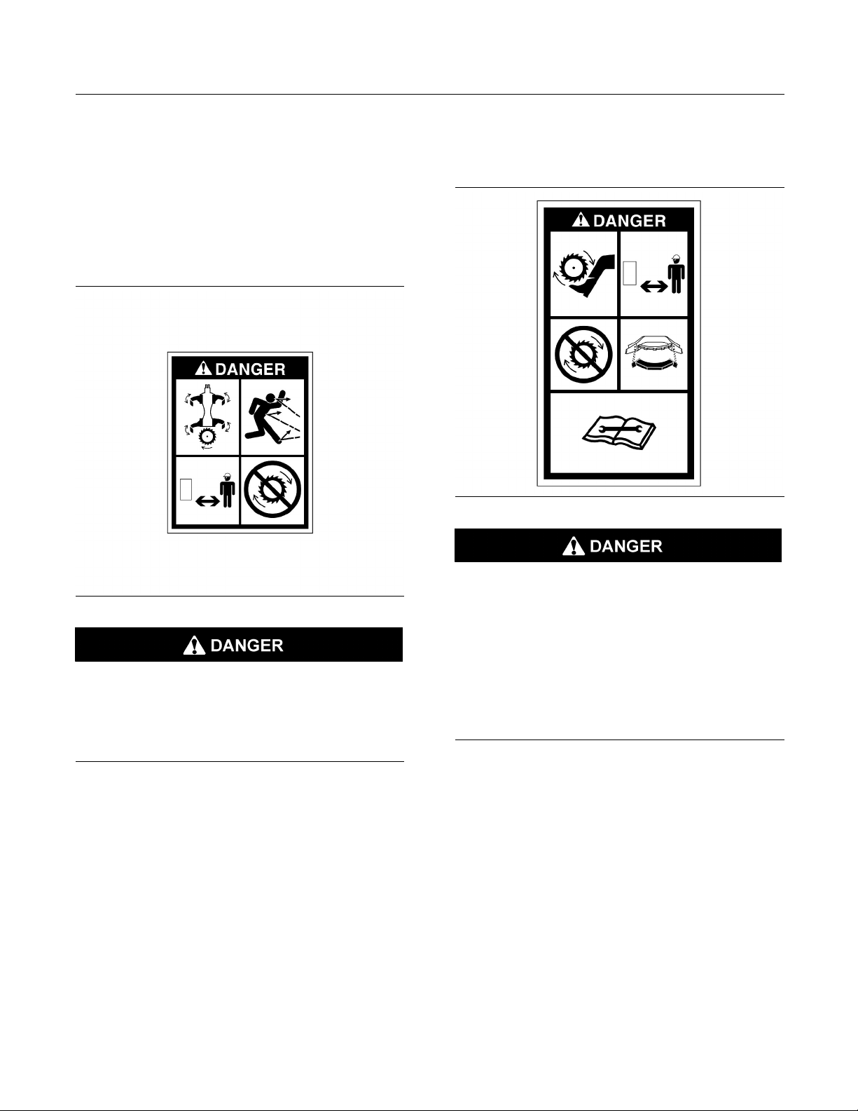
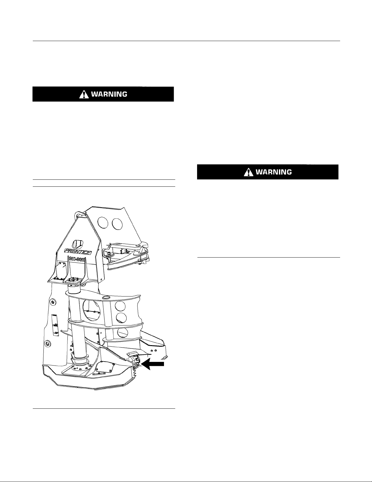
Flying Debris (1)
This danger m
sides of the frame of the felling head.
essage is located on the base on both
Cutting (2)
This danger message is located on the base on both
sides of the frame of the felling head.
g01683234
g01683255
The operation of the machine can cause debris to
fly. Stay clear of rotating blades and moving parts
during machine operation. Stop the rotation of the
cutting gear before approaching the machine. The
flying debris, moving parts and/or rotating blades
can cause serious injury or death.
Stay clear of the rotating cutting blade during machine operation. Stop the rotation of the c utting
blade and install the cutting guard before performing service work on the machine.
Do not operate or work on this machine unless
you have read and understand the instructions
andwarningsintheOperationandMaintenance
Manual and the Service Manuals. Failure to follow
the instructions or heed the warnings may result
in personal injury or death.
Page 7

SEBU8750 7
Safety Section
General Hazard Information
Pressurized Oil (3)
This warning message is located on the base on both
sides of the frame of the felling head.
g01683257
Personal injury can result from sudden release of
high pressure oil. Do not check for leaks with your
hands. A pinhole leak can penetrate the skin and
cause serious injury or possible death. Always
use a board or c ardboard when checking for leaks.
Release the pressure from the system before disconnecting oil lines. Read and understand the Operation and Maintenance Manual before performing any hydraulic system maintenance.
Cutting Hazard (4)
This warning message is located on the middle of the
base on the front side of the felling head.
g02533878
Hand cutting hazard from saw blade. Could cause
serious injury or death.
Keephandsawayfromthisareawhenblade
movement is possible.
i04548059
General Hazard Information
SMCS Code: 6319
Illustration 2
g00104545
Attach a “Do Not Operate” warning tag or a similar
warning tag to the start switch or to the controls.
Attach the warning tag before you service the
equipment or before you repair the equipment. These
warning tags (Special Instruction, SEHS7332) are
available from your Prentice dealer.
Page 8

8 SEBU8750
Safety Section
General Hazard Information
Operating the machine while distracted can result
inthelossofmachinecontrol.Useextremecaution when using any device while operating the
machine. Operating the machine while distracted
can result in personal injury or death.
Know the width of your equipment in order to maintain
proper clearance when you operate the equipment
near fences or near boundary obstacles.
Be aware of high voltage power lines and power
cables that are buried. If the machine comes in
contact with these hazards, serious injury or death
may occur from electrocution.
Never put maint
Drain all liquids into a suitable container.
Obey all local
Use all cleaning solutions with care. Report all
necessary re
Do not allow unauthorized personnel on the
equipment.
Unless you are instructed otherwise, perform
maintenanc
position. Refer to Operation and Maintenance Manual
for the procedure for placing the equipment in the
servicing
When you perform maintenance above ground level,
use approp
machines. If equipped, use the machine anchorage
points and use approved fall arrest harnesses and
lanyards
.
Pressuri
Pressurized air and/or water can cause debris and/or
hot wate
water could result in personal injury.
r to be blown out. The debris and/or hot
enance fluids into glass containers.
regulations for the disposal of liquids.
pairs.
e with the equipment in the servicing
position.
riate devices such as ladders or man lift
zed Air and Water
020
Illustration 3
Wear a hard hat, protective glasses, and other
protective equipment, as required.
Do not wear loose clothing or jewelry that can snag
on controls or on other parts of the equipment.
Make sure that all protective guards and all covers
are secured in place on the equipment.
Keep the equipment free from foreign material.
Remove debris, oil, tools, and other items from the
k, from walkways, and from steps.
dec
Secure all loose items such as lunch boxes, tools,
other items that are not a part of the equipment.
and
Know the appropriate work site hand signals and
e personnel that are authorized to give the hand
th
signals. Accept hand signals from one person only.
not smoke when you service an air conditioner.
Do
Also, do not smoke if refrigerant gas may be present.
Inhaling the fumes that are released from a flame that
ontacts air conditioner refrigerant can cause bodily
c
harm or death. Inhaling gas from air conditioner
refrigerant through a lighted cigarette can cause
odily harm or death.
b
g00702
When pre
used for cleaning, wear protective clothing, protective
shoes, and eye protection. Eye protection includes
goggle
The maximum air pressure for cleaning purposes
must b
nozzle is deadheaded and the nozzle is used with
an effective chip deflector and personal protective
equip
cleaning purposes must be below 275 kPa (40 psi).
ssurized air and/or pressurized water is
s or a protective face shield.
e reduced to 205 kPa (30 psi) when the
ment. The maximum water pressure for
Trapped Pressure
sure can be trapped in a hydraulic system.
Pres
Releasing trapped pressure can cause sudden
machine movement or attachment movement. Use
ion if you disconnect hydraulic lines or fittings.
caut
High-pressure oil that is released can cause a hose
to whip. High-pressure oil that is released can cause
to spray. Fluid penetration can cause serious
oil
injury and possible death.
Fluid Penetration
essure can be trapped in the hydraulic circuit long
Pr
after the engine has been stopped. The pressure can
cause hydraulic fluid or items such as pipe plugs to
cape rapidly if the pressure is not relieved correctly.
es
Page 9

SEBU8750 9
Safety Section
General Hazard Information
Do not remove an
until pressure has been relieved or personal injury
may occur. Do not disassemble any hydraulic
components or
or personal injury may occur. Refer to the Service
Manual for any procedures that are required to
relieve the h
Illustration 4
Always use a board or cardboard when you check
for a leak. Leaking fluid that is under pressure can
penetrate body tissue. Fluid penetration can cause
serious injury and possible death. A pin hole leak can
cause severe injury. If fluid is injected into your skin,
you must get treatment immediately. Seek treatment
from a doctor that is familiar with this type of injury.
y hydraulic components or parts
parts until pressure has been relieved
ydraulic pressure.
g00687600
Containing Fluid Spillage
Care must be taken in order to ensure that fluids
are contained during performance of inspection,
maintenance, testing, adjusting, and repair of the
equipment. Prepare to collect the fluidwithsuitable
containers before opening any compartment or
disassembling any component that contains fluids.
Inhalation
Illustration 5
Asbestos Information
Prentice equipment and replacement parts that
are shipped from Caterpillar are asbestos free.
Prentice recommends the use of only genuine Cat
replacement parts. Use the following guidelines
when you handle any replacement parts that contain
asbestos or when you handle asbestos debris.
Use caution. Avoid inhaling dust that might be
generated when you handle components that contain
asbestos fibers. Inhaling this dust can be hazardous
to your health. The components that may contain
asbestos fibers are brake pads, brake bands, lining
material, clutch plates, and some gaskets. The
asbestos that is used in these components is bound
in a resin or sealed in some way. Normal handling
is not hazardous unless airborne dust that contains
asbestos is generated.
If dust that may contain asbestos is present, there
are several guidelines that should be followed:
g02159053
Refer to Special Publication, NENG2500, “Caterpillar
Dealer Service Tool Catalog” for the following items:
Tools that are suitable for collecting fluids and
•
equipment that is suitable for collecting fluids
Tools that are suitable for containing fluids and
•
equipment that is suitable for containing fluids
Obey all local regulations for the disposal of liquids.
Never use compressed air for cleaning.
•
Avoid brushing materials that contain asbestos.
•
Avoid grinding materials that contain asbestos.
•
Useawetmethodinordertocleanupasbestos
•
materials.
A vacuum cleaner that is equipped with a high
•
efficiency particulate air filter (HEPA) can also be
used.
Use exhaust ventilation on permanent machining
•
jobs.
Wear an approved respirator if there is no other
•
way to control the dust.
Page 10

10 SEBU8750
Safety Section
Crushing Prevention and Cutting Prevention
Comply with app
•
for the work place. In the United States, use
Occupational Safety and Health Administration
(OSHA) requir
can be found in “29 CFR 1910.1001”.
Obey environ
•
of asbestos.
Stay away fr
•
particles in the air.
licable rules and regulations
ements. These OSHA requirements
mental regulations for the disposal
om areas that might have asbestos
Dispose of Waste Properly
Illustration 6
Improperly disposing of waste can threaten the
environment. Potentially harmful fluids should be
disposed of according to local regulations.
g00706404
Never jump acro
in order to start the engine. Unexpected machine
movement could result.
Whenever there are equipment control linkages the
clearance in the linkage area will change with the
movement of t
clear of areas that may have a sudden change in
clearance with machine movement or equipment
movement.
Stay clear of all rotating and moving parts.
If it is necessary to remove guards in order to perform
maintenance, always install the guards after the
maintenan
Keep objects away from moving fan blades. The fan
blade will
Do not use a kinked wire cable or a frayed wire cable.
Wear glov
When you strike a retainer pin with force, the retainer
pin can fly
personnel. Make sure that the area is clear of people
when you strike a retainer pin. To avoid injury to
your eye
a retainer pin.
Chips or
strike the object. Make sure that no one can be
injured by flying debris before striking any object.
s, wear protective glasses when you strike
other debris can fly off an object when you
ss the starter solenoid terminals
he equipment or the machine. Stay
ce is performed.
throw objects or cut objects.
es when you handle wire cable.
out. The loose retainer pin can injure
Always use leakproof containers when you drain
fluids. Do not pour waste onto the ground, down a
drain, or into any source of water.
i01359664
Crushing Prevention and
Cutting Prevention
SMCS Code: 6319
port the equipment properly before you perform
Sup
any work or maintenance beneath that equipment.
Do not depend on the hydraulic cylinders to hold
the equipment. Equipment can fall if a control is
up
moved, or if a hydraulic line breaks.
not work beneath the cab of the machine unless
Do
the cab is properly supported.
nless you are instructed otherwise, never attempt
U
adjustments while the machine is moving or while
the engine is running.
i04316817
Burn Prevention
SMCS Code: 6319
Do not touch any part of an operating work tool.
Allow the work tool to cool before any maintenance
is performed on the work tool. Relieve all pressure in
the air system, in the oil system, or in the lubrication
system before any lines, fittings, or related items are
disconnected.
Oils
Hot oil and hot components can cause personal
injury. Do not allow hot oil to contact the skin. Also,
do not allow hot components to contact the skin.
Remove the hydraulic tank filler cap only after the
engine has been stopped. The filler cap must be
cool enough to touch with a bare hand. Follow the
standard procedure in this manual in order to remove
the hydraulic tank filler cap.
Page 11

SEBU8750 11
Safety Section
Electrical Storm Injury Prevention
i01122596
Electrical Storm Injury
Prevention
SMCS Code: 6319
When lightning is striking in the vicinity of the
machine, the operator should never attempt the
following p
Mount the machine.
•
Dismount the machine.
•
If you are i
storm, stay in the operator's station. If you are on the
ground during an electrical storm, stay away from
the vicini
rocedures:
n the operator's station during an electrical
ty of the machine.
i01933657
Before Operation
SMCS Code: 6319
Clear all personnel from the area.
Clear all obstacles that are in the path of the machine.
Beware of hazards such as wires, ditches, etc.
Keep all window
machine. Always wear protective glasses. Always
wear the protective equipment that is recommended
in the work too
protective equipment that is required for the operating
environment.
To prevent personnel from being struck by flying
objects, ensure that all personnel are out of the work
area.
While you are performing any maintenance, any
testing, or
clear of the following areas: cutting edges, pinching
surfaces, and crushing surfaces.
s and doors closed on the host
l's operation manual. Wear any other
any adjustments to the work tool stay
i03634865
Operation
SMCS Code: 6319
Only operate the machine while you are in a seat.
The seat belt must be fastened while you operate the
machine. Only operate the controls while the engine
is running.
Check for proper operation of all controls and
protective devices while you operate the machine
slowly in an open area.
Whenever you are working around this product,
always wear: a hard hat, protective glasses, and
protective shoes. Whenever you are working around
this product, always wear the protective equipment
that is required by the conditions of the job site.
Refer to the Operation and Maintenance Manual,
“Daily Inspection” for more information on inspecting
the work tool before use.
i01908027
Work Tools
SMCS Code: 6319
Only use work tools that are recommended by your
authorized dealer for use on your machine.
If you are in doubt about the compatibility of a
particular work tool with your machine, consult your
authorized dealer.
Make sure that all necessary guarding is in place on
the host machine and on the work tool.
Before you move the machine, make sure that no
one will be endangered.
Do not allow riders on the machine unless the
machine has the following equipment:
additional seat
•
additional seat belt
•
Rollover Protective Structure (ROPS)
•
Never use the work tool for a work platform.
Report any needed repairs that were noted during
operation.
Carry attachments close to the ground, approximately
40 cm (15 inches) higher than ground level. Do not
go close to the edge of a cliff, an excavation, or an
overhang.
If the machine begins to sideslip, perform the
following procedure:
Discard the load.
•
Turn the machine downhill.
•
Page 12

12 SEBU8750
Safety Section
Parking
Be careful to av
oid any condition which could lead
to tipping. Tipping can occur when you work on
hills, banks and slopes. Also, tipping can occur
when you cross
ditches, ridges or other unexpected
obstructions.
Whenever it i
s possible, operate the machine up the
slopes and down the slopes. Avoid operating the
machine across the slope, when possible.
Keep the machine under control. Do not overload the
machine beyond capacity.
Be sure that the towing eyes and towing devices are
adequate.
Connect trailing equipment to a drawbar or to a hitch
only.
Never straddle a wire cable or allow other personnel
to straddle a wire cable.
When you maneuver to connect the equipment, make
sure that no personnel are between the machine
and trail
ing equipment. Block the hitch of the trailing
equipment in order to align the equipment with the
drawbar.
Know the maximum dimensions of your machine.
Deactivation of the hydraulic controls does not
prevent the blade, boom swing, or auxiliary circuit
functions from moving under gravity or other external forces. Gravity or other external forces can
move the blade, boom swing, or auxiliary circuit
functions suddenly if a hydraulic control lever is
moved.
Personal injury or death may occur from sudden
machine movement.
6. Turn the engine start switch to the OFF position
and remove the key.
7. Turn the battery disconnect switch to the OFF
position. If the machine will not be operated for
an extended period, remove the key in order to
avoid battery discharge that may be caused by a
battery short circuit, by the current draw via certain
components, or by vandalism.
Stay back until saw blade comes to complete stop
after shutdown. May cause serious injury or death.
Always k
eep the Rollover Protective Structure
(ROPS) installed during machine operation.
i04535372
Parking
SMCS Code: 6319
1. Park the machine on a level surface. If you must
park the machine on a downgrade, block the tires
or chock the tracks of the machine.
2. Apply the service brake in order to stop the
machine. Move the direction control switch to
NEUTRAL.
3. Engage the parking brake.
4. Lower all attachments to the ground. Make sure
that all attachments are in the recommended
servicing position before servicing the machine.
5. Move the hydraulic lockout control to the
LOCKED position. The hydraulic system remains
pressurized if the accumulator is charged. This
conditionistrueevenwhentheengineisnot
running. This pressure should decrease in a short
time (approximately 1 minute). While the hydraulic
system maintains a charge, the machine controls
remain functional.
Illustration 7
nstall the saw guard on the felling head.
8.I
g02714285
Page 13
SEBU8750 13
Product Information Section
General Information
Product Information
Section
General Information
i04535373
Specifications
SMCS Code: 6319
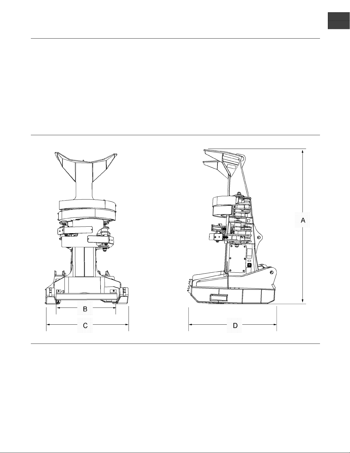
Illustration 8
g02719778
Page 14
14 SEBU8750
Product Information Section
General Information
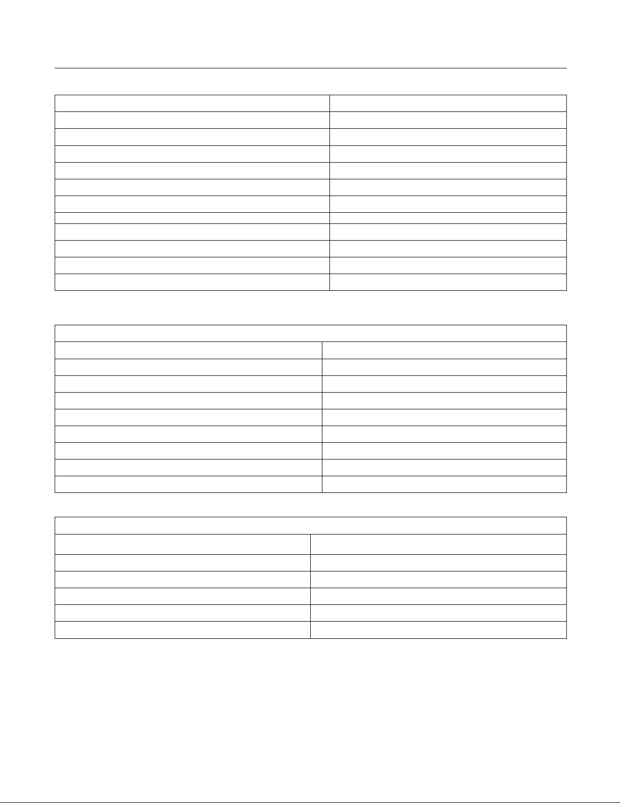
Table 1
Model SC57
Height (A) 3022.6 mm (119 inch)
Throat Clearance (B) 1244.6 mm (49 inch)
3.6 inch)
Speed of the Disc (Single Speed Disc)
(1)
no tilt or mount assembly
Table 2
Maximum Operating Pressure 26890 kPa (3900 psi)
Width (C) 1615.4 mm (6
Depth (D) 1778 mm (70 inch)
(1)
Weight
2971 kg (6550 lb)
1200 RPM
Flow of the Saw Motor 106 L/min (28 US gpm)
Pressure of the Saw Motor 27579 kPa (4000 psi)
Flow Rate of the Arm Cylinder 159 L/min (42 US gpm)
Pressure of the Arms 26.9MPa(3900psi)
Number of Disc Saw Teeth 16
Grapple and Accumulator Arm Cylinders
Quantity 2
Weight 33.6 kg (74 lb)
Typ e Double Acting
Cushion Head Ends
Bore
mm (3.5 inch)
88.9
Stroke 187.1 mm (7.4 inch)
Closed Length 765.6 mm (30.1 inch)
Rod Diameter
50.8 mm (2 inch)
Table 3
Motor
Function
Rotation of the Cutting Disc
Rotation Clockwise
Type Variable Displacement Piston Motor
Minimum Displacement 118cc(7.2in3)
Maximum Displacement 160 cc (9.8 in3)
Maximum Operating Pressure 34500 kPa (5000 psi)
Page 15
SEBU8750 15
Product Information Section
Identification Information
Identification Information
i04535377
Plate Locations and Film
Locations
SMCS Code: 6000; 6319
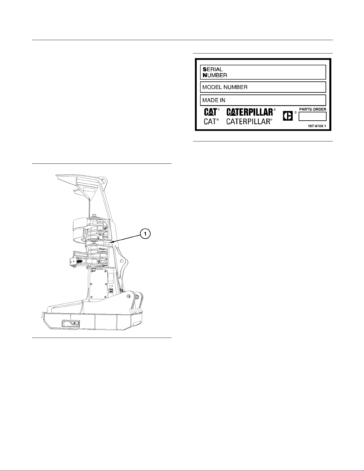
Serial Number
Prentice work tools are identified with serial numbers.
The serial number plate (1) is located on the left side
of the felling head near the grapple arms.
Illustration 10
Serial Number Plate
For quick reference, record the identification numbers
in the spaces that are provided below.
Serial Number of the Work Tool
Model Number______________________________________________
_________________________
g02719242
Illustration 9
(1) Serial Number Plate Location
g02719247
Page 16

16 SEBU8750
Operation Section
Operation
Operation Section
Operation
i04535391
Felling Head
SMCS Code: 6319
Illustration 11
g02719177
Illustration 12
(1) Moun
(2) Grap
(3) Col
(4) Pis
(5) Tre
(6) D is
(7) Deb
ting Bearings
ple Ar ms
lector Arm s
ton Motor
eBasket
cSaw
ris Chute
g02719197
Collector arm cylinders control the movement of
ctor arms (3). The collector arm cylinders close
colle
ontothelog.Holdingthetreeintheheadwhenthe
head cuts multiple trees.
Cylinders control the movement of grapple arm (2).
The grapple arm closes onto the log during felling
ree.
of a t
Piston motor (4) is mounted to an adapter plate
oupled to the drive shaft by a splined coupler.
and c
Hydraulic oil is supplied by a pump that is mounted
on the machine.
The disc saw rotates at a constant high speed in
order to fell a tree. The felling head is powered
ough the tree. The head clamps the tree to the
thr
head after the cutting is complete.
e debris chute allows debris to exit, reducing
Th
debris build-up on saw disc during operation.
ference: For more information on the disc saw,
Re
refer to Operation and Maintenance Manual, “Disc
Saw”.
Page 17
SEBU8750 17
Operation Section
Operation
i04535395
Disc Saw
SMCS Code: 6543
Sawhead discharge debris may be increased
in rough or hilly terrain. Heavier debris has the
potential t
aware of the flight angle of the sawhead discharge.
Avoid cutting when people, domestic animals,
building or personal property are located on the
discharge
as necessary to avoid possible damage caused
by the s aw discharge.
o travel greater distances. Always be
side of the saw. Reposition the disc saw
The disc saw is d
maximum speed of the disc saw is adjusted at the
saw pump on the machine. The disc saw is not
adjustable. T
controlled by a bushing. The bushing is installed in
the head of the piston motor.
For more information on the disc saw, refer to
Operation and Maintenance Manual, “Disc Saw Clean/Insp
ect/Replace”.
riven by a piston motor. The
he displacement of the piston motor is
i04535415
Saw Tooth
SMCS Code: 6543
Sawhead discharge debris may be increased
in rough or hilly terrain. Heavier debris has the
potenti
aware of the flight angle of the sawhead discharge.
Avoid cutting when people, domestic animals,
building or personal property are located on the
discha
as necessary to avoid possible damage caused
by the saw discharge.
al to travel greater distances. Always be
rge side of the saw. Reposition the disc saw
Illustration 13
g02702719
Page 18

18 SEBU8750
Operation Section
Operation
Illustration 1 4
Thediscsawcanbeequippedwithtwotypesof
teeth: steel beaver teeth and super carbide teeth.
Thesupercarbideteethshouldbeusedinsevere
hi-impact harvesting conditions. The super carbide
teeth have a high cutting ability. The steel beaver
teeth are used under normal conditions. The super
carbideoptionisusedinsandyareasthatwould
otherwise shorten the life of standard teeth. The
cutting edge of the teeth is retained throughout the
life of the teeth.
The disc saw teeth can be rotated in order to prolong
service life.
Reference: For other information on the disc saw
teeth, refer to Operation and Maintenance Manual,
“Disc Saw Tooth - Inspect/Replace”.
g00938876
Page 19
SEBU8750 19
Operation Section
Operating Techniques
Operating Techniques
i04535453
Operating Technique
Informatio
SMCS Code: 6319
Improper use of the boom and work tools could
result in i
aware of all the functions for the joystick control
and proper operating techniques.
The operation of the machine can cause debris to
fly. Stay clear of rotating blades and moving parts
during machine operation. Stop the rotation of the
cutting gear before approaching the machine. The
flying debris, moving parts and/or rotating blades
can cause serious injury or death.
njury or death. The operator must be fully
n
Flying debris, falling trees, limbs, and tops, can
cause serious injury or death. Do not operate the
saw within 91 m (300 ft) of personnel or machinery.
NOTICE
Teeth breaking when hitting a rock can damage the
tooth seat o
disc is recommended and more economical. When using a segmented disc, only the tooth and the segment
must usuall
the tooth seat.
General Me
n the saw disc. The use of a segmented
y be replaced if the broken tooth damages
thod of Operation
Stay clear of the rotating cutting blade during machine operation. Stop the rotation of the cutting
blade and install the cutting guard before performing service work on the machine.
Do not operate or work on this machine unless
you have read and understand the instructions
and warnings in the Operation and Maintenance
Manual and the Service Manuals. Failure to follow
the instructions or heed the warnings may result
in personal injury or death.
Do not use Feller Bunchers to harvest trees in a
fallen or blown over condition. Serious personal
injury or death will occur from high velocity projectiles being thrown through the cab window.
Feller Bunchers are not designed to harvest fallen or blown over trees. Serious personal injury or
ath will occur.
de
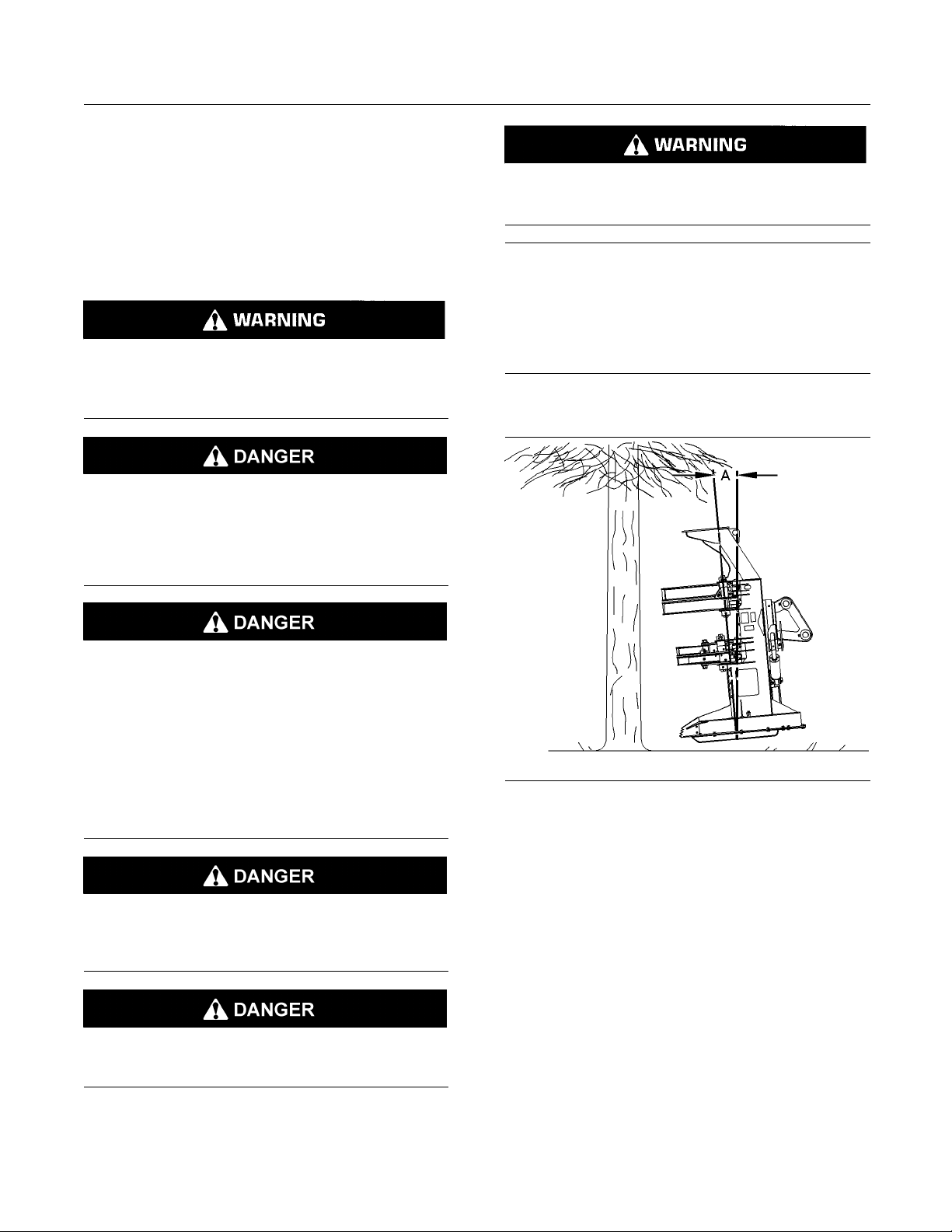
Illustration 15
1. Position the felling head forward by 3 to 5 degrees
(A) when you approach a tree.
Note: Ensure that the disc saw is rotating at sufficient
speed. Feeding the blade too slowly you will cause
unnecessary friction on the blade and the speed of
the blade will decrease. Feeding the blade too quickly
will damage the stem of the tree.
2. Thefellingheadmustlineupwiththetree.
g00725587
Page 20
20 SEBU8750
Operation Section
Operating Techniques
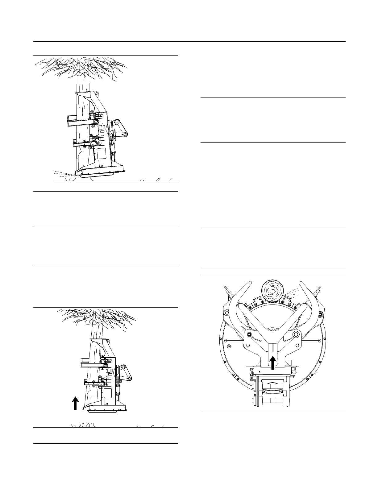
Illustration 16
g00725597
3. Feed the disc saw through the tree in a smooth
continuous motion.
5. Oncethetreeis
severed, raise the felling head
off the stump.
6. Tiltthetreeb
ackward slightly in order to get
the center of gravity closer to the center of the
machine. This will improve the control of the tree.
NOTICE
Do not push the tree into position. Hard impacts will
damage the head and booms. Ensure that the butt
end of the tree does not touch the blade or hit against
the guard of the saw motor once the tree has been
released.
7. Tilt the felling head forward. Open the arms and
release the tree.
Note: The disc saw will continue to free wheel for
several minutes after you shut off the blade. In order
to stop rotation, slowly cut into a stump. The disc
saw can be brought to a complete stop in a matter
of seconds.
Cutting Multiple T r ees
NOTICE
Do not clamp the tree until after the cut is complete.
Subjecting the tree to clamping forces before the cut
is complete may damage the stem and unnecessarily
bind or stall the saw blade.
4. As the head cuts the tree, begin to close the
grapple arms and the collector arms. Immediately
after the cut is complete, close the grapple arms
and the collector arms tightly.
NOTICE
Do not operate any other function while the disc saw
is cutting the tree. Tilting or moving the felling head
before the stem is cut through can damage the disc
saw.
Illustration 17
g00725604
Illustration 18
g00725458
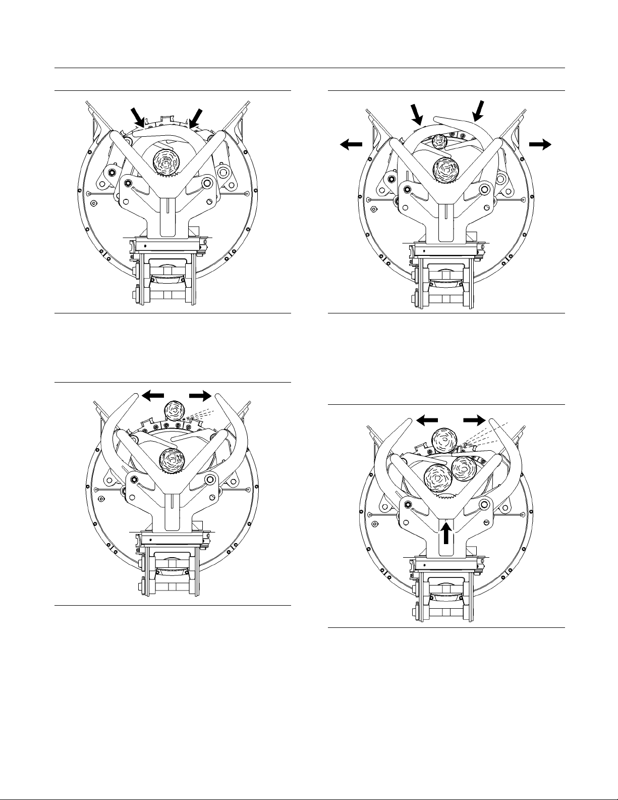
1. Open the grapple arms and the collector arms.
Advance the felling head by extending the boom
and the stick or by moving the machine forward.
Cut the first tree.
Page 21
SEBU8750 21
Operation Section
Operating Techniques
Illustration 19
g00725463
2. Immediately close the grapple arms and the
collector arms on the tree. Advance to the next
tree.
Illustration 20
g00725466
Illustration 21
g00725469
4. Close the grapple arms on the second tree. The
collector arms move outward. The collector arms
spring back to the open position. The arms will
then close in order to grip the tree. Advance to
the next tree.
3. Open the grapple arms. The collector arms hold
the first tree. Cut the second tree.
Illustration 22
g00725473
5. Open the grapple arms. The collector arms now
hold both trees. Cut the third tree.
Page 22
22 SEBU8750
Operation Section
Operating Techniques
Illustration 23
g00725479
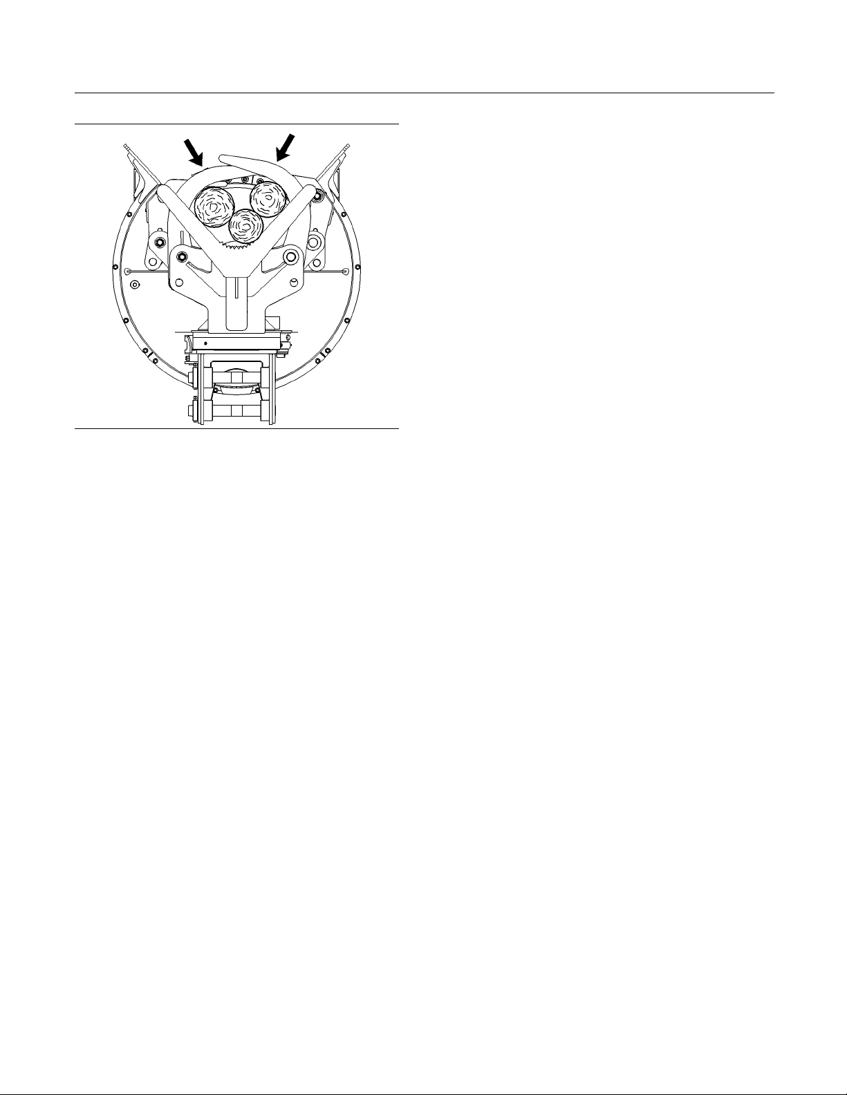
6. When you travel, keep the grapple arms and the
collector arms on the tree s.
Page 23

SEBU8750 23
Maintenance Section
Lubricant Viscosities and Refill Capacities
Maintenance Section
Lubricant Viscosities and
Refill Capacities
i01979962
Lubricant Viscosities
SMCS Code: 6319; 7581
The hydraulic oil that operates the piston motor, the
grapple arm cylinders and the collector arm cylinders
is supplied by the machine.
Reference: For information about the hydraulic
oil, refer to Operation and Maintenance Manual,
“Lubricant Viscosities and Refill Capacities” for the
machine that is being serviced.
The proper viscosity grade is determined by the
minimum outside temperature when the machine is
started. The proper viscosity grade is also determined
by the maximum outside temperature while the
machine is operated. Refer to the “Min” column on
the table in order to determine the viscosity grade
that is required for starting a cold machine and for
operating a cold machine. Refer to the “Max” column
on the table in order to select the viscosity grade for
operating the machine at the highest temperature
that is anticipated.
Consult your dealer for additional information.
Table 4
Lubricant Viscosities for Ambient Temperatures
Compartment or System Oil Type and Classification Oil Viscosities
HYDO
DEO
TDTO
Hydraulic System
Lubricating System BIO HYD (HEES)
Grease Points MPGM -25 175 -13 347
MTO
API CG-4
API CF-4
API CF
TO-4
SAE 0W30
SAE 0W20
SAE 5W20
SAE 10W
SAE 30 -10 10 -14 50
°C °F
Min Max Min Max
-40 10 -40 50
40 10 -40 50
30 10 -22 50
-30 20 -22 68
-7
+32 +20 +90
Page 24

24 SEBU8750
Maintenance Section
Maintenance Interval Schedule
i04535456
Maintenance Interval Schedule
SMCS Code: 6319
Every 10 Service Hours or Daily
Bearing (Side Tilt) - Lubricate ............................... 25
Bearing for Accumulator Arm - Lubricate .............. 25
Bearing for
Bearing for Output Shaft - Lubricate ..................... 28
Bearings (Cylinder Ends) - Lubricate .................... 28
Disc Saw - Cl
Disc Saw Tooth - Inspect/Replace ........................ 30
Output Shaft End Play - Check ............................. 32
Grapple Arm - Lubricate ..................... 27
ean/Inspect/Replace ....................... 29
Initial 25
Felling Head - Check ............................................ 32
Every 100
Piston Motor (Disc Saw) Area - Clean .................. 34
Every 50
Disc Saw Tooth - Inspect/Replace ........................ 30
Every 10
Disc Saw - Clean/Inspect/Replace ....................... 29
Service Hours
Service Hours or 2 Weeks
0 Service Hours
00 Service Hours
Page 25

SEBU8750 25
Maintenance Section
Bearing (Side Tilt) - Lubricate
i04535497
Bearing (Side Tilt) - Lubricate
SMCS Code: 7551-086
Tilt
i04535498
Bearing f or Accumulator Arm
- Lubricate
SMCS Code: 7551-086-UA
Illustration 24
Rear View
1. Wipe o
ff all fittings before lubricating.
g0271
2. Lubricate each fitting with grease. There are a
loffourfittings(twooneachside).
tota
8956
Illustration 25
Hand Side View
Left-
g02718772
Page 26

26 SEBU8750
Maintenance Section
Bearing for Accumulator Arm - Lubricate
Illustration 26
nd Rear View
Left-Ha
g02718654
Illustration 28
and Rear View
Right-H
g02718658
1. Wipe off all fittings before lubricating.
2. Lubricate each fitting with grease. There are a
total of six fittings.
Illustration 27
Right-Hand Side View
g02718781
Page 27

SEBU8750 27
Maintenance Section
Bearing for Grapple Arm - Lubricate
i04535499
Bearing for Grapple Arm Lubricate
SMCS Code: 7551-086-HAR
Illustration 29
hand Grapple Arm Grease Locations
Left-
g02718310
Illustration 30
and Grapple Arm Grease Locations
Right-h
g02718326
1. Wipe off all fittings before lubricating.
2. Lubricate each fitting with grease. There are a
total of six fittings.
Page 28
28 SEBU8750
Maintenance Section
Bearing for Output Shaft - Lubricate
Bearing for Output Shaft Lubricate
SMCS Code: 7551-086-D6
i04535503
i04535504
Bearings (Cylinder Ends) Lubricate
SMCS Code: 7551-086
Grease Points
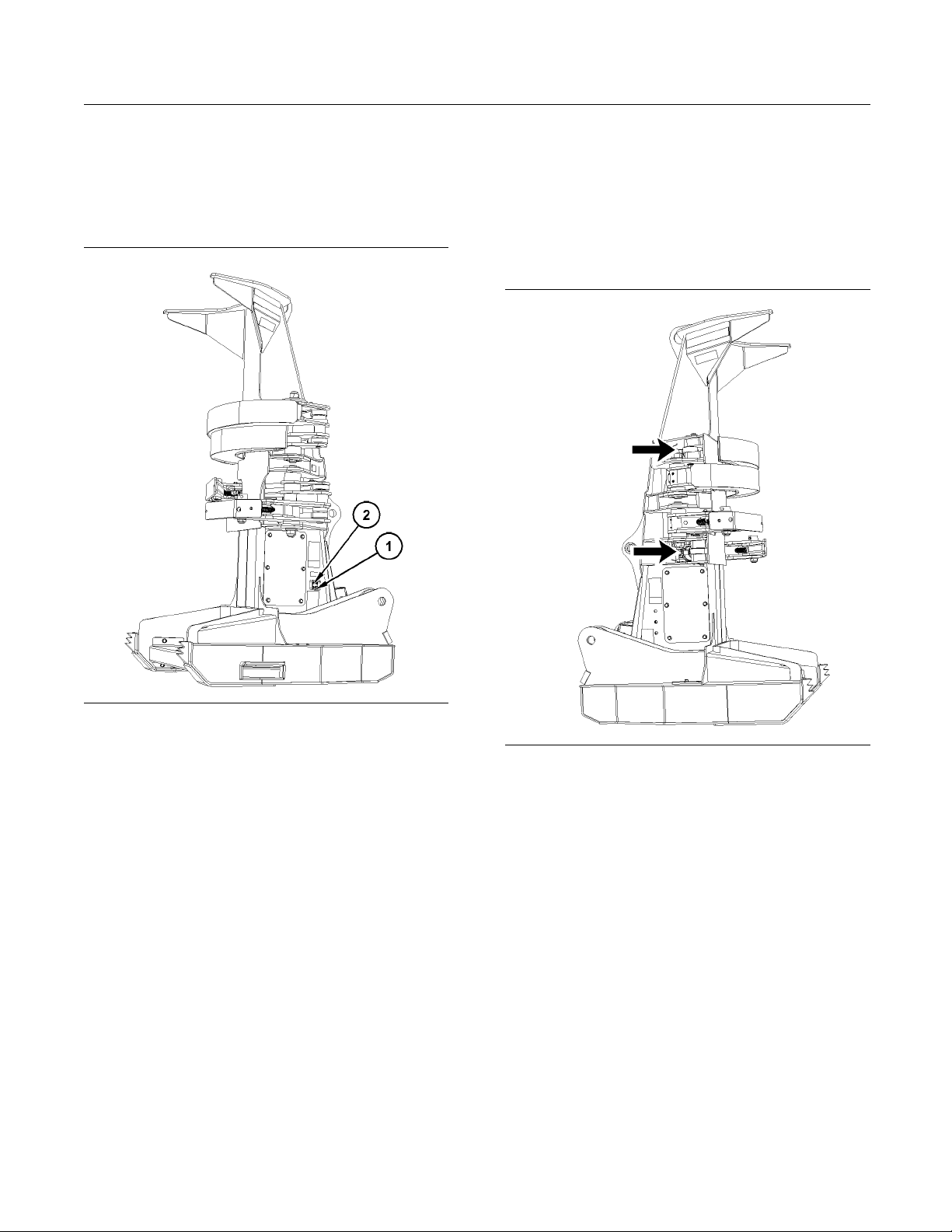
Illustration 31
ease Fitting
(1) Gr
ease Vent
(2) Gr
g02718257
1. Wipe off grease fitting (1) before lubricating.
2. Lubricate grease fittings (1) until grease exits
grease vents (2).
tration 32
Illus
Right Hand Side
g02718094
Page 29
SEBU8750 29
Maintenance Section
Disc Saw - Clean/Inspect/Replace
Stay back until saw blade comes to complete stop
after shutdown. May cause serious injury or death.
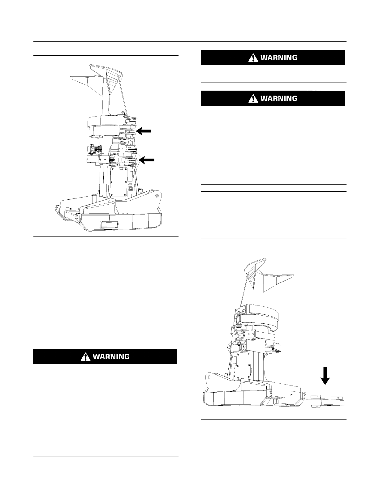
Illustration 33
Left Han
dSide
g02718102
1. Wipe off all fittings before lubricating.
2. Lubricate each fitting with grease. A fitting is
locatedontheendofeachcylinder.
Sawhead disc
harge debris may be increased
in rough or hilly terrain. Heavier debris has the
potential to travel greater distances. Always be
aware of the
flight angle of the sawhead discharge.
Avoid cutt
ing when people, domestic animals,
building or personal property are located on the
discharge side of the saw. Reposition the disc saw
as necessa
ry to avoid possible damage caused
by the saw discharge.
NOTICE
Do not weld on the disc saw. Do not attempt to repair
the disc saw if damaged or there are signs of cracks.
Replace the disc saw. Rebalancing of the disc saw
must be performed by authorized personnel only.
i04535509
Disc Saw - Clean/Inspect/
Replace
SMCS Code: 6543-040; 6543-070; 6543-510
Accidental machine starting can cause injury or
th to personnel working on the machine.
dea
T o avoid accidental machine starting, turn the bat-
ry disconnect switch to the OFF position and re-
te
move the k ey. If the machine is not equipped with
a battery disconnect switch, disconnect the bat-
ry cables from the battery and tape the battery
te
clamps.
lace a do not operate tag at the battery discon-
P
nect switch location to inform personnel that the
machineisbeingworkedon.
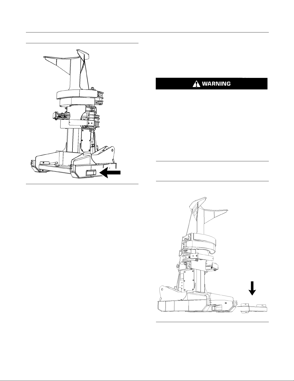
lustration 34
Il
1. Remove the saw guard.
2. Remove any dirt or debris that may have
accumulatedonthediscsaw.
g02718231
Page 30
30 SEBU8750
Maintenance Section
Disc Saw Tooth - Inspect/Replace
i04535510
Disc Saw Tooth Inspect/Repl
SMCS Code: 6543-040; 6543-510
Accidental machine starting can cause injury or
death to personnel working on the machine.
To avoid accidental machine starting, turn the battery disconnect switch to the OFF position and remove the key. If the machine is not equipped with
a battery disconnect switch, disconnect the battery cables from the battery and tape the battery
clamps.
Place a do not operate tag at the battery disconnect switch location to inform personnel that the
machine is being worked on.
ace
Illustration 35
3. Re move a
accumulated in the debris chute. The debris chute
is located on the lower left-hand disc saw frame.
4. Visually inspect the disc saw for irregularities at
every 500 hours of use. Irregularities that are
obser
and further inspected for visible irregularities
in removed parts that are not visible on the
assem
5. If the damage is excessive, replace the disc saw.
Reference: For more information on removing
andinstallingthediscsaw,refertoDisassembly
and A
Note: Bolts for the disc saw teeth must be replaced
er 1000 hours of operation. Do not use bolts that
aft
have been damaged or show any defects upon
inspection.
ny dirt or debris that may have
ved the disc saw should be disassembled
bled disc saw.
ssembly, UENR0743, “Disc Saw - Remove”.
g02716026
Inspect
Note: Bolts for the disc saw teeth must be replaced
after being torqued to specification more than twice.
not use bolts that have been damaged or show
Do
any defects upon inspection.
place the saw guard.
6. Re
lustration 36
Il
1. Remove the saw guard.
g02718231
Page 31
SEBU8750 31
Maintenance Section
Disc Saw Tooth - Inspect/Replace
Illustration 3 7
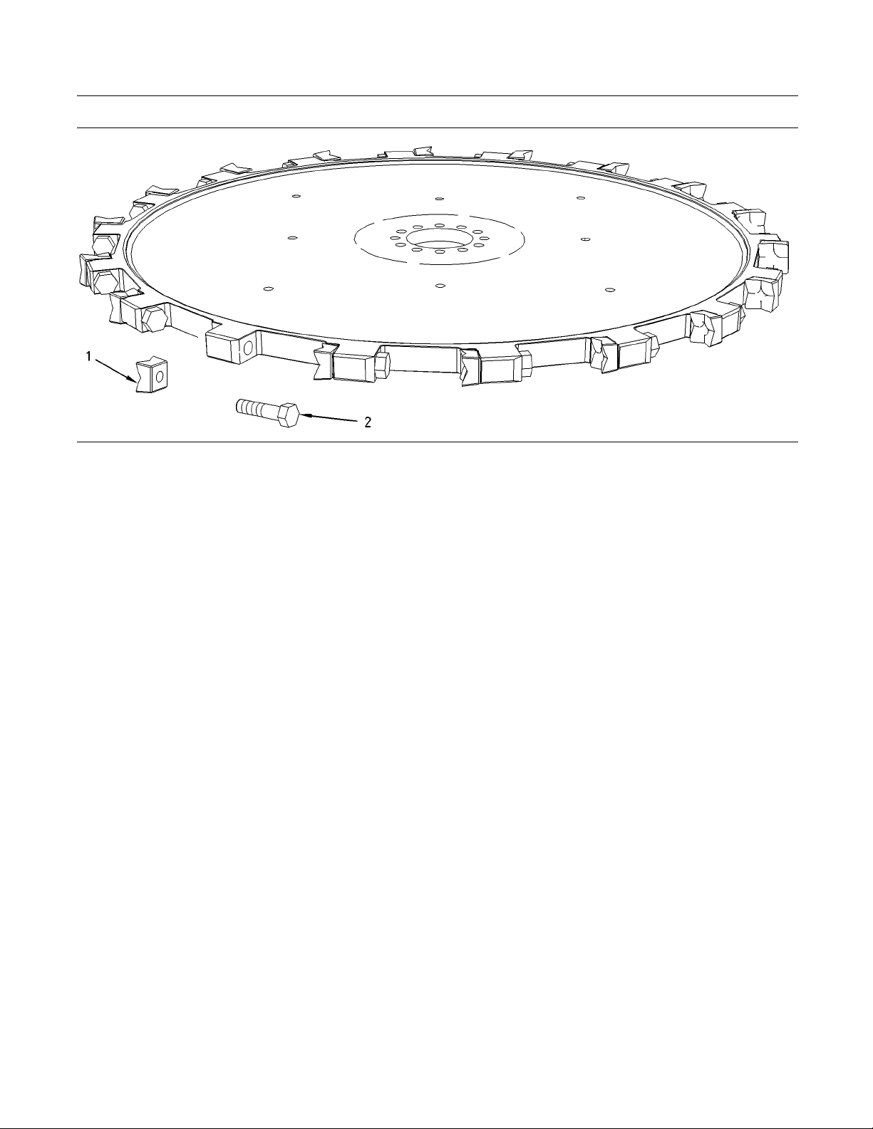
2. Inspect each bolt (2) for cracks, damage, or
excessive wear. Replace any bolts that are
damaged or worn. Check the torque of each
bolt. Tighten bolts to a torque of 407 ± 27 N·m
(300±20lbft).
Note: Bolts must be replaced at every 1000 service
hours.
3. Inspect each tooth (1) for cracks, damage, or
excessive wear. Replace teeth that are damaged
or worn.
Tooth Wear
The following signs will indicate tooth wear:
Increased cutting time
•
Excessive smoking
•
Rough cutting surface
•
Excessive temperature of the tooth
•
g00938945
Note: A measurement of 54.1 mm (2.13 inch) or less
constitutes a worn cutting edge. Refer to point (B) in
Illustration 38.
Note: When you replace teeth, install the teeth on
opposite sides (180°) of the disc saw to each other.
An unbalanced load could otherwise occur. Replace
all excessively worn teeth at the same time.
1. Loosen bolt (2).
2. Tap bolt head (2) until tooth (1) has moved
outward.
3. Remove bolt (2) and tooth (1) from the disc saw.
4. Ensure that all mating surfaces are clean and free
of burrs.
5. Check for clearance. The tooth must be seated
tightly against the disc saw.
6. Install tooth (1) into the disc saw with bolt (2).
Tighten bolt (2) to a torque of 407 ± 27 N·m
(300 ± 20 lb ft).
Replace
The following signs indicate that the disc saw teeth
will need to be replaced:
Damaged teeth
•
Missing segments of teeth
•
Unbalanced load
•
Worn cutting edges
•
Note: Use a new bolt when you replace a tooth.
7. Install the saw guard.
Page 32

32 SEBU8750
Maintenance Section
Felling Head - Check
Positioning
Illustration 38
The following conditions should be met when you
position the cutting edges of the tooth:
g00938947
Hydraulic hose
•
Rpm of the piston motor
•
Hydraulic pressure
•
Reference: R
Saw Speed - Test and Adjust” in order to check
the rpm of the piston motor.
Reference: Refer to Testing and Adjusting,
“Piston Motor (Disc Saw) - Test and Adjust” in
order to che
2. Lubricate all grease fittings.
sandfittings
efer to T esting and Adjusting, “Disc
ck the hydraulic pressures.
i03292026
Output Shaft E nd Play - Check
SMCS Code: 3253-535
Accidental machine starting can cause injury or
death to personnel working on the machine.
The cutting edge tooth should be positioned at the
•
outermost point (A) from the center of the disc saw.
The cutting edge tooth should be positioned at the
•
widest point (B) between the top and the bottom
of the tooth.
i01981928
Felling Head - Ch eck
SMCS Code: 6319-535
Accidental machine starting can cause injury or
death to personnel working on the machine.
T o avoid accidental machine starting, turn the battery disconnect switch to the OFF position and remove the k ey. If the machine is not equipped with
a battery disconnect switch, disconnect the battery cables from the battery and tape the battery
clamps.
Place a do not operate tag at the battery disconnect switch location to inform personnel that the
machineisbeingworkedon.
To avoid accidental machine starting, turn the battery disconnect switch to the OFF position and remove the key. If the machine is not equipped with
a battery disconnect switch, disconnect the battery cables from the battery and tape the battery
clamps.
Place a do not operate tag at the battery disconnect switch location to inform personnel that the
machine is being worked on.
1. Remove any dirt or debris that may have
accumulatedonthediscsaw.
Illustration 39
g01219202
1. After initial operation of the felling head, the
following items should be checked:
Bolt torques
•
Page 33

SEBU8750 33
Maintenance Section
Output Shaft End Play - Check
2. Place wood bloc
ks at suitable locations under
the felling head. The blocks should be placed on
level ground. The blocks should provide a large
base for suppo
rt. Use only wood blocks which will
support the weight of the felling head.
Illustration 40
g01219204
3. Once the wood blocks are in place, slowly lower
the felling head until the felling head is fully
supported by the wood blocks.
Note: Thefellingheadmustbeblockedtoasuitable
height off the ground in order to allow a lifting device
below the disc saw.
Illustration 42
g01678438
5. Insert the locking pin in order to restrict additional
rotation of the blade.
Make sure that the felling head is stable before
you proceed.
ustration 41
Ill
g01678437
4. Rotate the blade at least three full revolutions
order to properly seat the top tapered roller
in
bearing.
Illus
tration 43
g01678439
6. Place a dial indicator on the blade through the
12.7 m
m (0.5 inch) inspection opening on the
plate. Set the dial to 0 or note the dial's position.
01678441
Illustration 44
g
7. Place a lifting device so that the lifting device is
located directly below the output shaft.
Page 34
34 SEBU8750
Maintenance Section
Piston Motor (Disc Saw) Area - Clean
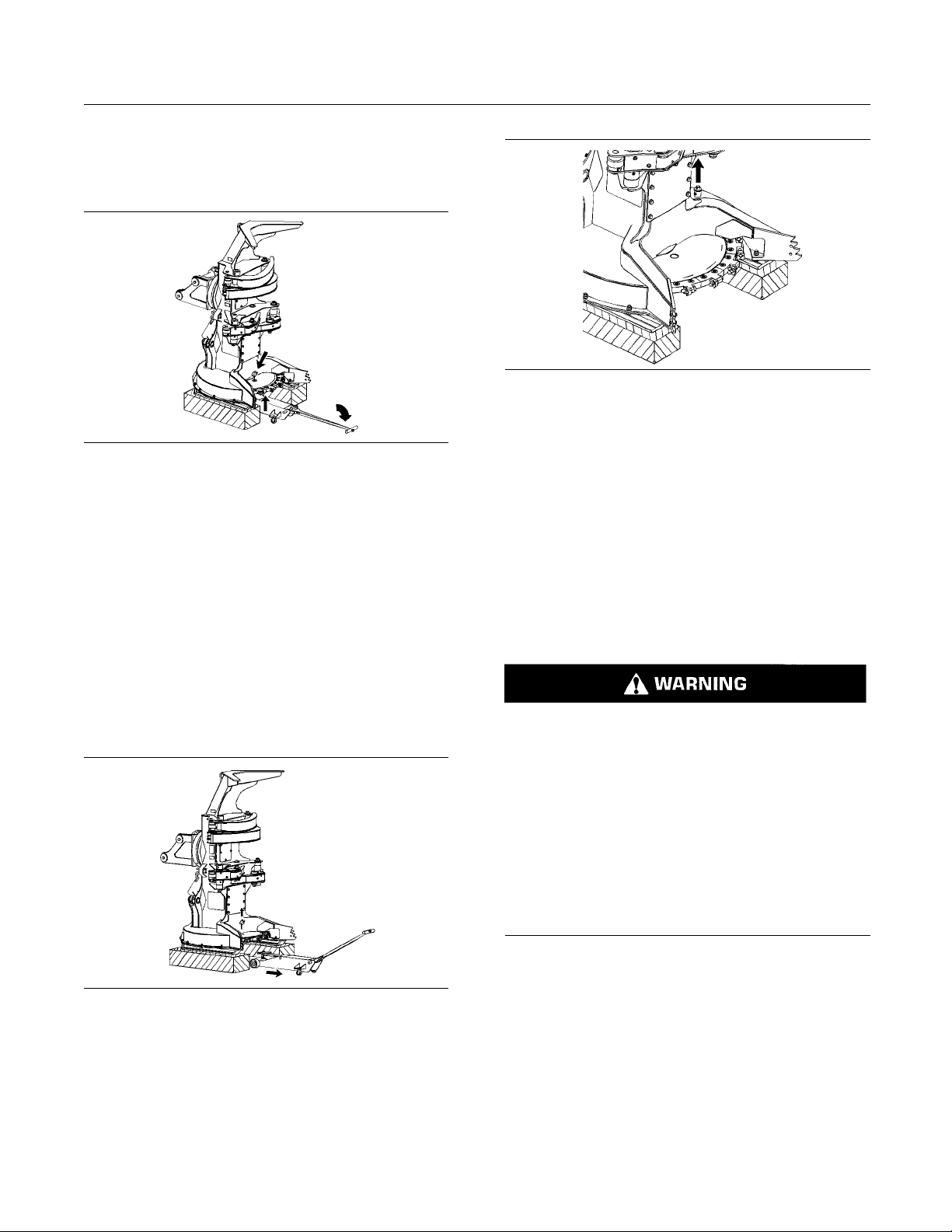
8. Place a block on
the lifting device in order to help
support and protect the output shaft. The output
shaft should rest fully on the block and on the
lifting devic
Illustration 45
e.
g01678444
9. Raise the lifting device in order to apply an upward
force on the output shaft. Note the reading on
the dial indicator. If the motion of the output
shaft is greater than the maximum of 0.23 mm
(0.009 inch), adjustment is required.
Note: Do not operate the felling head before you
measure the motion of the output shaft. The felling
head must be cold when you measure the motion
of the output shaft.
Illustration 47
g01678451
12. Remove the locking pin in order to allow the blade
to rotate.
Note: Damage to the work tool or damage to the
machine can occur if the locking pin is not removed
before returning the felling head back to operation.
i04535521
Piston M
otor ( Disc Saw ) Area
- Clean
SMCS Co
de: 5058-070
10. If the motion of the output shaft exceeds the
specification, refer to the Disassembly and
Assembly, “Output Shaft - Install” in order to adjust
the output shaft end play.
Illustration 46
the motion of the output shaft is within the given
11.If
g01678447
specification, lower the lifting device. Remove the
lifting device from below the felling head.
Note: Do not forget to remove the dial indicator
before returning the felling head back to operation.
ental machine starting can cause injury or
Accid
death to personnel working on the machine.
oid accidental machine starting, turn the bat-
To av
tery disconnect switch to the OFF position and remove the key. If the machine is not equipped with
tery disconnect switch, dis connect the bat-
abat
tery cables from the battery and tape the battery
clamps.
Place a do not operate tag at the battery disconnect switch location to inform personnel that the
hine is being worked on.
mac
Page 35
SEBU8750 35
Maintenance Section
Piston Motor (Disc Saw) Area - C lean
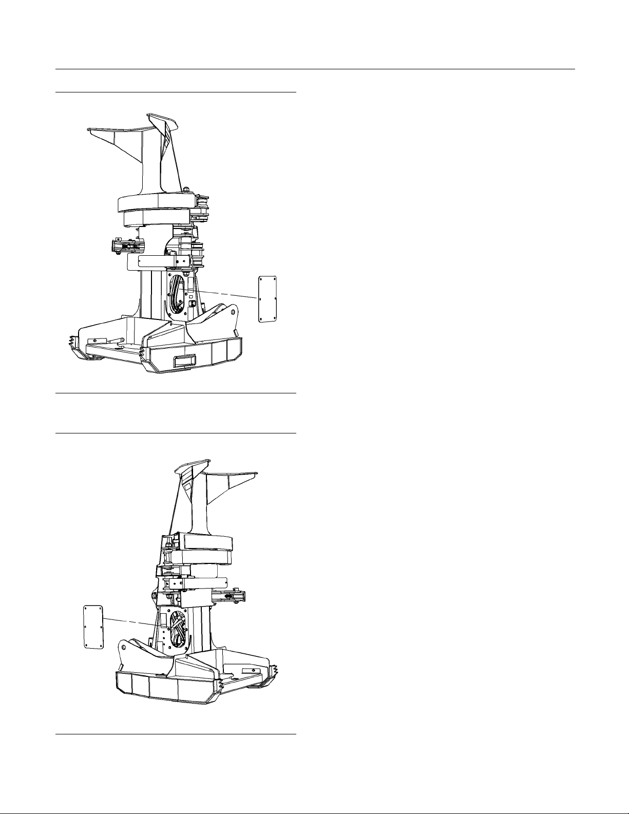
1. Remove the moto
r covers. There is a cover on
both sides of the Felling Head frame.
2. Clean any debr
is from the motor. Inspect all hoses
for damage or leaks. Check for loose bolts. Make
any necessary repairs.
3. Install motor covers.
Illustration 48
Left Han
d Side of Felling Head
g02715838
Illustration 49
Right Hand Side of Felling Head
g02715839
Page 36

36 SEBU8750
Reference Information Section
Reference Materials
Reference Information
Section
Reference Materials
i04535523
Reference Material
SMCS Code: 6319
Reference Material
Parts Manual, SEBP5138, “SC-57 Felling Head”
•
Service Manual, UENR0743, “SC-57 Felling Head”
•
Special Publication, NENG2500, “Tools and Shop
•
Products Guide”
Special Publication, SEBU6250, “Machine Fluids
•
Recommendations”
Specifications, RENR3130, “Torque Specifications”
•
Page 37

SEBU8750 37
Index Section
Index
B
Bearing (Sid
Tilt ...................................................................... 25
Bearing for Accumulator Arm - Lubricate .............. 25
Bearing for
Bearing for Output Shaft - Lubricate...................... 28
Bearings (Cylinder Ends) - Lubricate..................... 28
Grease Poin
Before Operation .................................................... 11
Burn Prevention..................................................... 10
Oils..................................................................... 10
C
Crushing Prevention and Cutting Prevention ........ 10
D
Disc Saw................................................................ 17
Disc Saw - Clean/Inspect/Replace ........................ 29
Disc Saw
Inspect ............................................................... 30
Positioning ......................................................... 32
Replac
Tooth Wear......................................................... 31
e Tilt) - Lubricate ................................ 25
Grapple Arm - Lubricate...................... 27
ts .................................................... 28
Tooth - Inspect/Replace......................... 30
e.............................................................. 31
I
Identificati
Important Safety Information ................................... 2
L
Lubricant V
Lubricant Viscosities and Refill Capacities ............ 23
M
Maintenan
Maintenance Section ............................................. 23
O
Operati
Cutting Multiple Trees ........................................ 20
General Method of Operation ............................ 19
Operati
Operation.......................................................... 11, 16
Operation Section.................................................. 16
Output
on Information ....................................... 15
iscosities.............................................. 23
ce Interval Schedule ............................. 24
ng Technique Information .......................... 19
ng Techniques............................................ 19
Shaft End Play - Check.............................. 32
E
rical Storm Injury Prevention .......................... 11
Elect
F
Felling Head .......................................................... 16
ing Head - Check ............................................. 32
Fell
Foreword ................................................................. 4
Literature Information........................................... 4
tenance ........................................................ 4
Main
Operation ............................................................. 4
Safety................................................................... 4
G
General Hazard Information ...................... .............. 7
Containing Fluid Spillage ..................................... 9
spose of Waste Properly ................................ 10
Di
Fluid Penetration.................................................. 8
Inhalation ............................................................. 9
essurized Air and Water ................................... 8
Pr
Trapped Pressure ................................................ 8
General Information............................................... 13
P
Parking .................................................................. 12
n Motor (Disc Saw) Area - Clean ................... 34
Pisto
Plate Locations and Film Locations....................... 15
Serial Number .................................................... 15
ct Information Section .................................. 13
Produ
R
Reference Information Section .............................. 36
rence Material ................................................ 36
Refe
Reference Material............................................. 36
Reference Materials .............................................. 36
S
Safety Messages ..................................................... 5
Safety Section ......................................................... 5
w Tooth.............................................................. 17
Sa
Specifications ........................................................ 13
T
able of Contents..................................................... 3
T
Page 38

38 SEBU8750
Index Section
W
Work Tools.............................................................. 11
Page 39

Product and Dealer Infor mation
Note: For product identification plate locations, see the section “Product Identification Information” in the Operation
and Maintenance Manual.
Delivery Date:
Product Information
Model:
Product Identification Number:
Engine Serial Number:
Transmission Serial Number:
Generator Serial Number:
Attachment Serial Numbers:
Attachment Information:
Customer Equipment Number:
Dealer Equipment Number:
Dealer Inform atio n
Name: Branch:
Address:
Dealer Contact Phone Number Hours
Sales:
Parts:
Service:
Page 40

©2011 Caterpillar
All Rights Reserved
Cat, Caterpillar, their respective logos, “Caterpillar Yellow” and the Power edge
trade dress, as well as corporate and product identity used herein, are trademarks
of Caterpillar and may not be used without permission.
 Loading...