

Page 1

OPERATOR’S MANUAL
WHEEL FELLER
BUNCHER
OPERATOR’S MANUAL 2470 2570 2670
HARVESTER HEAD
PE44
Part No. SEBU9062
March 2012
Rev. 00
Part No. 30009235
Rev. No. 0503, 0904
©Blount Inc. 2006. All Rights Reserved.
Page 2
i02653977
Important Safety Information
Most accidents that involve product operation, maintenance and repair are caused by failure to observe
basic safety rules or precautions. An accident can often be avoided by recognizing potentially hazardous
situations before an accident occurs. A person must be alert to potential hazards. This person should also
have the necessary training, skills and tools to pe rform these functions properly.
Improper operation, lubrication, maintenance or repair of this product can be dangerous and
could result in injury or death.
Do not operate or perform any lubrication, maintenance or repair on this product, until you have
read and understood the operation, lubrication, maintenance and repair information.
Safety precautions and warnings are provided in this manual and on the product. If these hazard warnings
are not heeded, bodily injury or death could occur to you or to other persons.
The hazards are identified by the “Safety Alert Symbol” and followed by a “Signal Word” such as
“DANGER”, “WARNING” or “CAUTION”. The Safety Alert “WARNING” label is shown below.
The meaning of this safety alert symbol is as follows:
Attention! Become Alert! Your Safety is Involved.
The message that appears under the warning explains the hazard and can be either written or pictorially
presented.
Operations that may cause product damage are identified by “NOTICE” labels on the product and in
this publication.
Prentice cannot anticipate every possible circumstance that might involve a potential hazard. The
warnings in this publication and on the product are, therefore, not all inclusive. If a tool, procedure,
work method or operating technique that is not specifically recommended by Prentice is used,
you must satisfy yourself that it is safe for you and for others. You should also ensure that the
product will not be damaged or be made unsafe by the operation, lubrication, maintenance or
repair procedures that you choose.
The information, specifications, and illustrations in this publication are on the basis of in formation th at
was available at the time that the publication was written. The specifications, torques, pressures,
measurements, adjustments, illustrations, and other items can change at an y time. These changes can
affect the service that is given to the product. Obtain the complete and most current information before you
start any job. Prentice dealers have the most current information available.
When replacement parts are required for this
product Prentice recommends using Prentice
replacement parts or parts with equivalent specifications including, but not limited to, physical
dimensions, type, strength and material.
Failure to heed this warning can lead to premature failures, product damage, personal injury or
death.
Page 3

SEBU9062 3
Table of Contents
Table of Contents
Foreword ................................................................. 4
Safety Section
Safety Messages .................................................... 5
General Hazard Information ................................... 8
Crushing Prevention and Cutting Prevention ......... 11
Burn Prevention ..................................................... 11
Fire Prevention and Explosion Prevention ............ 12
Electrical Storm Injury Prevention ......................... 15
Before Operation .................................................. 15
Operation .............................................................. 15
Work Tools ............................................................ 16
Parking .................................................................. 16
Product Information Section
General Information .............................................. 17
Identification Information ....................................... 19
Operation Section
Operation .............................................................. 20
Maintenance Section
Maintenance Support ............................................ 22
Maintenance Interval Schedule ............................ 23
Reference Information Section
Reference Materials .............................................. 42
Index Section
Index ..................................................................... 43
Page 4

4 SEBU9062
Foreword
Foreword
Literature Information
This manual sh
compartment in the literature holder or seat back
literature storage area.
This manual contains safety information, operation
instructions, transportation information, lubrication
informatio
Some photographs or illustrations in this publication
show detail
tool. Guards and covers might have been removed
for illustrative purposes.
Continuing improvement and advancement of
product design might have caused changes to your
work tool w
Read, study and keep this manual with the machine
that your work tool is installed on.
Whenever a question arises regarding your work tool,
or this publication, please consult your Caterpillar
dealer f
or the latest available information.
Safety
ould be stored in the operator's
n and maintenance information.
s that can be different from your work
hich are not included in this publication.
Maintenance
The maintenan
care. The illustrated, step-by-step instructions are
grouped by service intervals. Items without specific
intervals are
Items in the maintenance intervals schedule are
referenced to detailed instructions that follow.
Maintenance Intervals
Calendar in
can be used instead of service hour meter intervals
if they provide more convenient servicing schedules
and approxi
reading. Recommended service should always be
performed at the interval that occurs first.
Under extremely severe, dusty or wet operating
conditions, more frequent lubrication than is specified
in the mai
necessary.
Perform s
requirement. For example, at every 500 service
hours or 3 months, also service those items listed
under ev
10 service hours or daily.
ce section is a guide to equipment
listed under the when required interval.
tervals shown (daily, weekly, monthly, etc)
mate the indicated service hour meter
ntenance intervals schedule might be
ervice on items at multiples of the original
ery 250 service hours or monthly and every
The safety section lists basic safety precautions. In
on, this section identifies the text and locations
additi
of safety signs and labels used on the work tool.
Read an
in the safety section before operating or performing
lubrication, maintenance and repair on this work tool.
d understand the basic precautions listed
Operation
Theoperationsectionisareferenceforthenew
operator and a refresher for the experienced
ator. This section includes a discussion of
oper
gauges, switches, machine controls, work tool
controls, transportation and towing information.
Photographs and illustrations guide the operator
through correct procedures of checking, starting,
rating and stopping the work tool.
ope
Operating techniques outlined in this publication are
ic. Skill and techniques develop as the operator
bas
gains knowledge of the work tool and its capabilities.
Page 5

SEBU9062 5
Safety Section
Safety Messages
Safety Section
i04852170
Safety Messages
SMCS Code: 6320
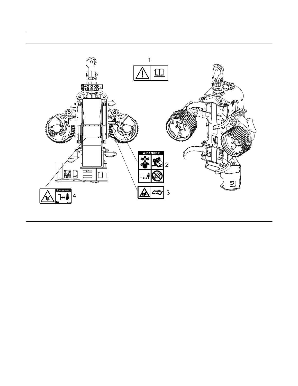
There are se
work tool. The exact location of the safety messages
and the description of the safety messages are
reviewed i
with all safety messages.
Make sure t
Clean the safety messages or replace the safety
messages if you cannot read the words. Replace the
safety me
When you clean the safety messages, use a cloth,
water, and soap. Do not use solvent, gasoline, or
other ha
Solvents, gasoline, or harsh chemicals could loosen
the adhesive that secures the safety message. Loose
adhesiv
Replace any safety message that is damaged, or
missin
that is replaced, install a safety message on the
replacement part. Any Prentice dealer can provide
new saf
veral specific safety messages on this
n this section. Please become familiarized
hat all of the safety messages are legible.
ssages if the illustrations are not legible.
rsh chemicals to clean the safety messages.
e will allow the safety message to fall.
g. If a safety message is attached to a part
ety messages.
Page 6
6 SEBU9062
Safety Section
Safety Messages
Illustration 1
g02976699
Page 7
SEBU9062 7
Safety Section
Safety Messages
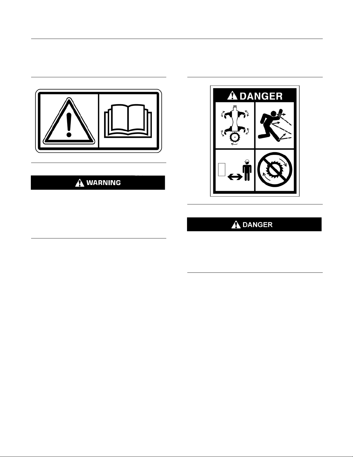
Do Not Operate (1)
This warning message is located on the inside
surface of the right window of the host machine.
g01370904
Do not operate or work on this equipment unless
you have read and understand the instructions
and warnings in the Operation and Maintenance
Manual. Failure to follow the instructions or heed
the warnings could result in injury or death. Contact any Prentice dealer for replacement manuals.
Proper care is your r esponsibility.
Flying Debris (2)
This danger message is located in the middle of the
frame on both sides of the harvester head.
g02631677
The operation of the mac hine can cause debris to
fly. Stay clear of rotating blades and moving parts
during machine operation. Stop the rotation of the
cutting gear before approaching the machine. The
flying debris, moving parts and/or rotating blades
can cause serious injury or death.
Page 8
8 SEBU9062
Safety Section
General Hazard Information
Cutting Hazard (3)
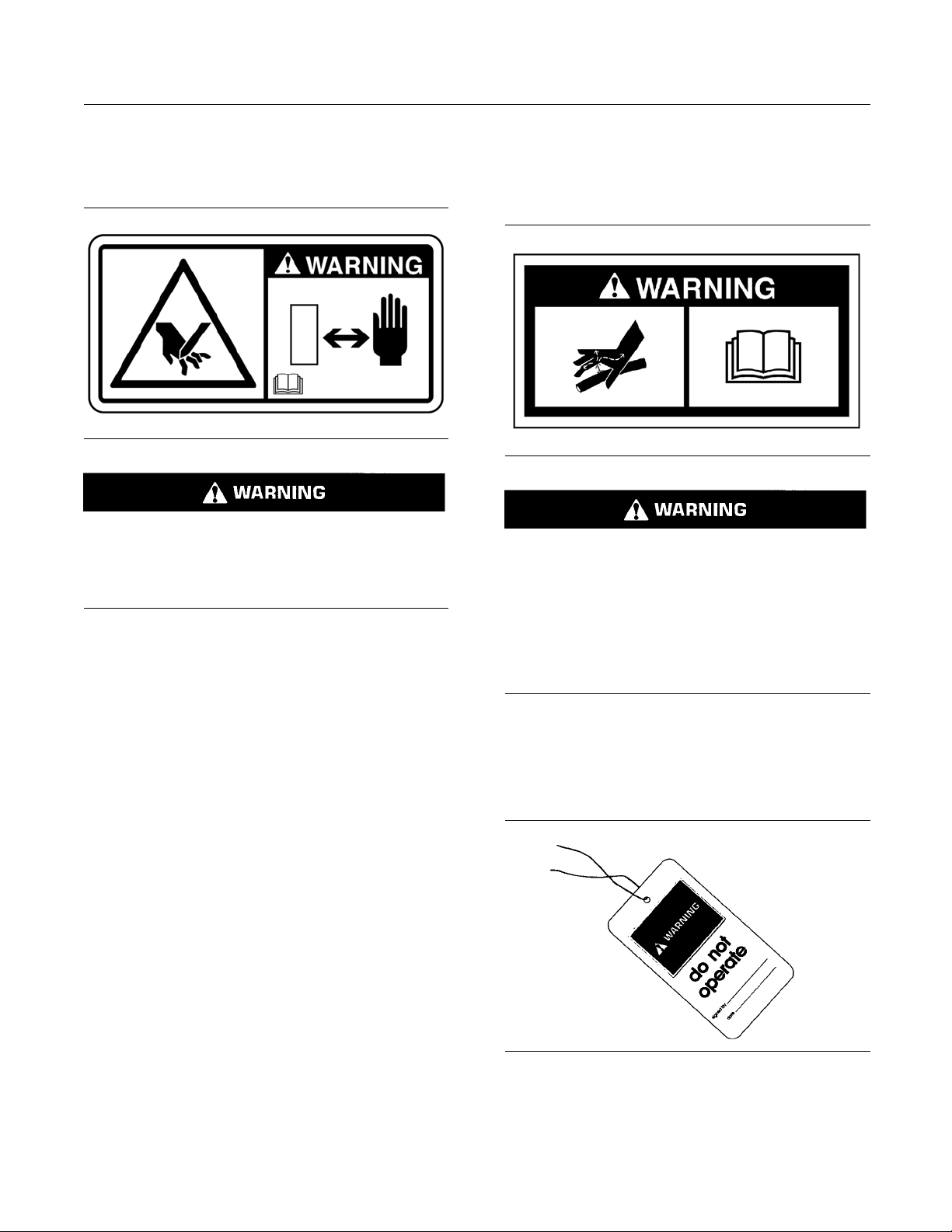
This warning message is located in the middle of the
frame on both sides of the harvester head.
g02533878
Hand cutting hazard from saw blade. Could cause
serious injury or death.
Keep hands away from this area when blade
movement is possible.
Pressurized Oil (4)
This warning message is located on the accumulator
bracket under the cover on the back of the harvester
head.
g0168325
Personal injury can result from sudden release of
high pressure oil. Do not check for leaks with your
hands. A pinhole leak can penetrate the skin and
cause serious injury or possible death. Always
use a board or cardboard when checking for leaks.
Release the pressure from the system before disconnecting oil lines. Read and understand the Operation and Maintenance Manual before performing any hydraulic system maintenance.
7
General Hazard Information
SMCS Code: 6320
Illustration 2
g00104545
i04837989
Page 9
SEBU9062 9
Safety Section
General Hazard Information
Attach a “Do Not
warning tag to the start switch or to the controls.
Attach the warning tag before you service the
equipment or b
warning tags (Special Instruction, SEHS7332) are
available from your Prentice dealer.
Operating t
inthelossofmachinecontrol.Useextremecaution when using any device while operating the
machine. Op
can result in personal injury or death.
Know the wi
proper clearance when you operate the equipment
near fences or near boundary obstacles.
Be aware of high voltage power lines and power
cables that are buried. If the machine comes in
contact w
may occur from electrocution.
ith these hazards, serious injury or death
Operate” warning tag or a similar
efore you repair the equipment. These
he machine while distracted can result
erating the machine while distracted
dth of your equipment in order to maintain
Do not smoke whe
Also, do not smoke if refrigerant gas may be present.
Inhaling the fumes that are released from a flame that
contacts air c
harm or death. Inhaling gas from air conditioner
refrigerant through a lighted cigarette can cause
bodily harm o
Never put maintenance fluids into glass containers.
Drain all li
Obey all local regulations for the disposal of liquids.
Use all cleaning solutions with care. Report all
necessary repairs.
Do not allow unauthorized personnel on the
equipment.
Unless you are instructed otherwise, perform
maintenance with the equipment in the servicing
position
for the procedure for placing the equipment in the
servicing position.
When you perform maintenance above ground level,
use appropriate devices such as ladders or man lift
machine
points and use approved fall arrest harnesses and
lanyards.
quids into a suitable container.
. Refer to Operation and Maintenance Manual
s. If equipped, use the machine anchorage
n you service an air conditioner.
onditioner refrigerant can cause bodily
rdeath.
Illustration 3
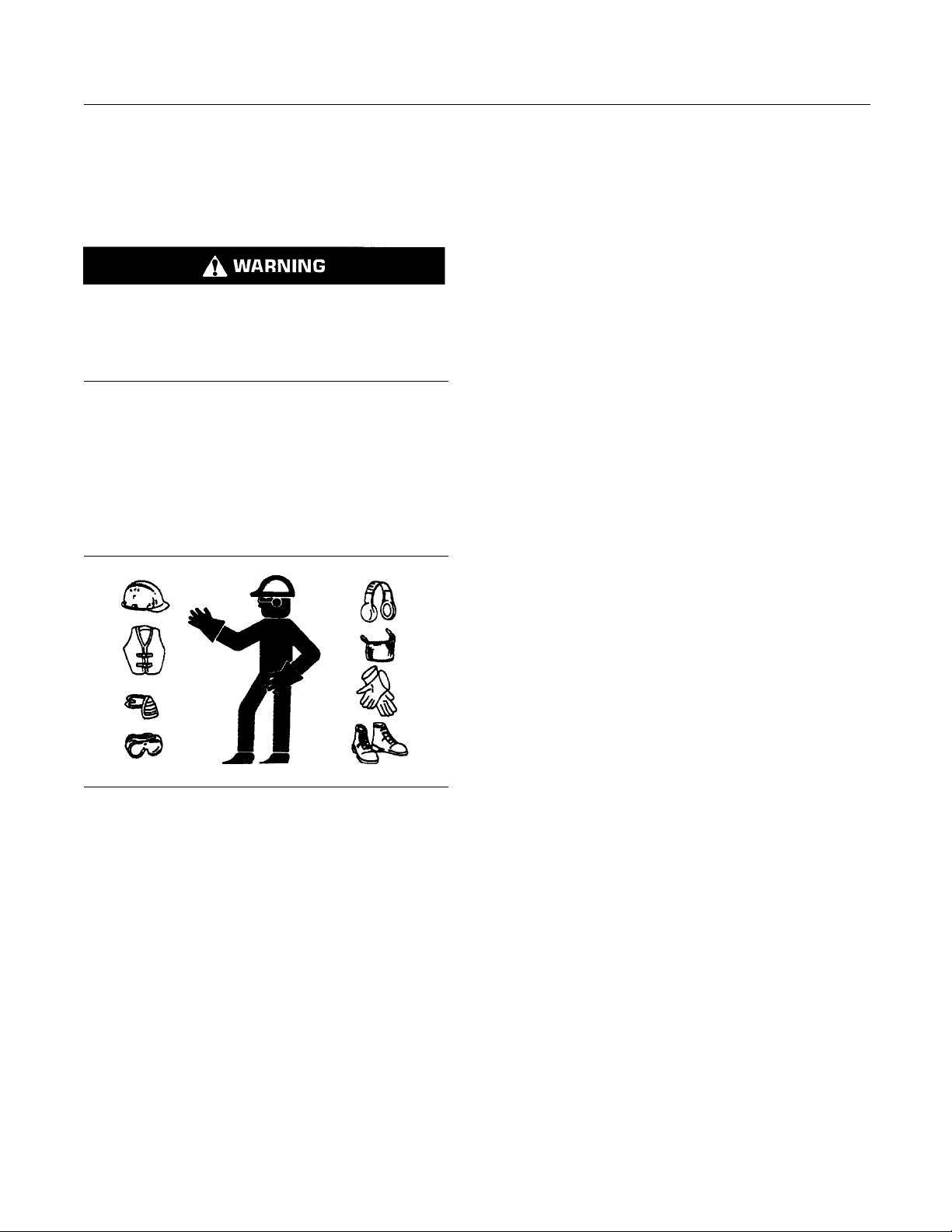
Wear a hard hat, protective glasses, and other
protective equipment, as required.
Do not wear loose clothing or jewelry that can snag
on controls or on other parts of the equipment.
Make sure that all protective guards and all covers
are secured in place on the equipment.
Keep the equipment free from foreign material.
Remove debris, oil, tools, and other items from the
deck, from walkways, and from steps.
Secure all loose items such as lunch boxes, tools,
and other items that are not a part of the equipment.
Know the appropriate work site hand signals and
the personnel that are authorized to give the hand
signals. Accept hand signals from one person only.
g00702020
Pressurized Air and Water
Pressurized air and/or water can cause debris and/or
hot water to be blown out. The debris and/or hot
could result in personal injury.
water
When pressurized air and/or pressurized water is
or cleaning, wear protective clothing, protective
used f
shoes, and eye protection. Eye protection includes
goggles or a protective face shield.
The maximum air pressure for cleaning purposes
must be reduced to 205 kPa (30 psi) when the
le is deadheaded and the nozzle is used with
nozz
an effective chip deflector and personal protective
equipment. The maximum water pressure for
aning purposes must be below 275 kPa (40 psi).
cle
pped Pressure
Tra
Pressure can be trapped in a hydraulic system.
easing trapped pressure can cause sudden
Rel
machine movement or attachment movement. Use
caution if you disconnect hydraulic lines or fittings.
gh-pressure oil that is released can cause a hose
Hi
to whip. High-pressure oil that is released can cause
oil to spray. Fluid penetration can cause serious
jury and possible death.
in
Page 10
10 SEBU9062
Safety Section
General Hazard Information
Fluid Penetration
Pressure can b
after the engine has been stopped. The pressure can
cause hydraulic fluid or items such as pipe plugs to
escape rapidl
Do not remove any hydraulic components or parts
until pressu
may occur. Do not disassemble any hydraulic
components or parts until pressure has been relieved
or personal
Manual for any procedures that are required to
relieve the hydraulic pressure.
e trapped in the hydraulic circuit long
y if the pressure is not relieved correctly.
re has been relieved or personal injury
injury may occur. Refer to the Service
Inhalation
Illustration 5
Asbestos Information
Prentice equipment and replacement parts that are
shipped from Prentice are asbestos free. Prentice
recommends the use of only genuine Prentice
replacement parts. Use the following guidelines
when you handle any replacement parts that contain
asbestos or when you handle asbestos debris.
g02159053
Illustration 4
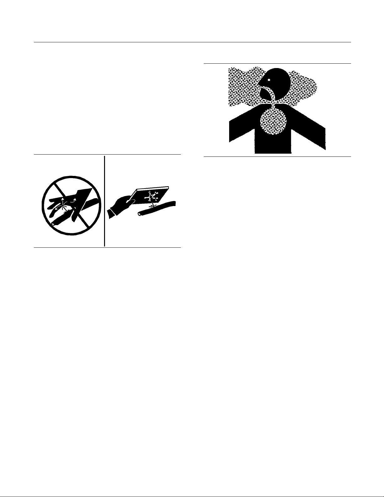
Always use a board or cardboard when you check
for a leak. Leaking fluid that is under pressure can
penetrate body tissue. Fluid penetration can cause
serious injury and possible death. A pin hole leak can
cause severe injury. If fluid is injected into your skin,
you must get treatment immediately. Seek treatment
from a doctor that is familiar with this type of injury.
g00687600
Containing Fluid Spillage
Care must be taken in order to ensure that fluids
are contained during performance of inspection,
maintenance, testing, adjusting, and repair of the
equipment. Prepare to collect the fluidwithsuitable
containers before opening any compartment or
disassembling any component that contains fluids.
Refer to Special Publication, NENG2500, “Caterpillar
Dealer Service Tool Catalog” for the following items:
Tools that are suitable for collecting fluids and
•
equipment that is suitable for collecting fluids
Use caution. Avoid inhaling dust that might be
generated when you handle components that contain
asbestos fibers. Inhaling this dust can be hazardous
to your health. The components that may contain
asbestos fibers are brake pads, brake bands, lining
material, clutch plates, and some gaskets. The
asbestos that is used in these components is bound
in a resin or sealed in some way. Normal handling
is not hazardous unless airborne dust that contains
asbestos is generated.
If dust that may contain asbestos is present, there
are several guidelines that should be followed:
Never use compressed air for cleaning.
•
Avoid brushing materials that contain asbestos.
•
Avoid grinding materials that contain asbestos.
•
Useawetmethodinordertocleanupasbestos
•
materials.
A vacuum cleaner that is equipped with a high
•
efficiency particulate air filter (HEPA) can also be
used.
Tools that are suitable for containing fluids and
•
equipment that is suitable for containing fluids
Obey all local regulations for the disposal of liquids.
Use exhaust ventilation on permanent machining
•
jobs.
Wear an approved respirator if there is no other
•
way to control the dust.
Page 11
SEBU9062 11
Safety Section
Crushing Prevention and Cutting Prevention
Comply with app
•
for the work place. In the United States, use
Occupational Safety and Health Administration
(OSHA) requir
can be found in “29 CFR 1910.1001”.
Obey environ
•
of asbestos.
Stay away fr
•
particles in the air.
licable rules and regulations
ements. These OSHA requirements
mental regulations for the disposal
om areas that might have asbestos
Dispose of Waste Properly
Illustration 6
Improperly disposing of waste can threaten the
environment. Potentially harmful fluids should be
disposed of according to local regulations.
g00706404
Never jump acro
in order to start the engine. Unexpected machine
movement could result.
Whenever there are equipment control linkages the
clearance in the linkage area will change with the
movement of t
clear of areas that may have a sudden change in
clearance with machine movement or equipment
movement.
Stay clear of all rotating and moving parts.
If it is necessary to remove guards in order to perform
maintenance, always install the guards after the
maintenan
Keep objects away from moving fan blades. The fan
blade will
Do not use a kinked wire cable or a frayed wire cable.
Wear glov
When you strike a retainer pin with force, the retainer
pin can fly
personnel. Make sure that the area is clear of people
when you strike a retainer pin. To avoid injury to
your eye
a retainer pin.
Chips or
strike the object. Make sure that no one can be
injured by flying debris before striking any object.
s, wear protective glasses when you strike
other debris can fly off an object when you
ss the starter solenoid terminals
he equipment or the machine. Stay
ce is performed.
throw objects or cut objects.
es when you handle wire cable.
out. The loose retainer pin can injure
Always use leakproof containers when you drain
fluids. Do not pour waste onto the ground, down a
drain, or into any source of water.
i01359664
Crushing Prevention and
Cutting Prevention
SMCS Code: 6320
port the equipment properly before you perform
Sup
any work or maintenance beneath that equipment.
Do not depend on the hydraulic cylinders to hold
the equipment. Equipment can fall if a control is
up
moved, or if a hydraulic line breaks.
not work beneath the cab of the machine unless
Do
the cab is properly supported.
nless you are instructed otherwise, never attempt
U
adjustments while the machine is moving or while
the engine is running.
i04316817
Burn Prevention
SMCS Code: 6320
Do not touch any part of an operating work tool.
Allow the work tool to cool before any maintenance
is performed on the work tool. Relieve all pressure in
the air system, in the oil system, or in the lubrication
system before any lines, fittings, or related items are
disconnected.
Oils
Hot oil and hot components can cause personal
injury. Do not allow hot oil to contact the skin. Also,
do not allow hot components to contact the skin.
Remove the hydraulic tank filler cap only after the
engine has been stopped. The filler cap must be
cool enough to touch with a bare hand. Follow the
standard procedure in this manual in order to remove
the hydraulic tank filler cap.
Page 12
12 SEBU9062
Safety Section
Fire Prevention and Explosion Prevention
i04550337
Fire Prevention and Explosion
Prevention
SMCS Code: 6320
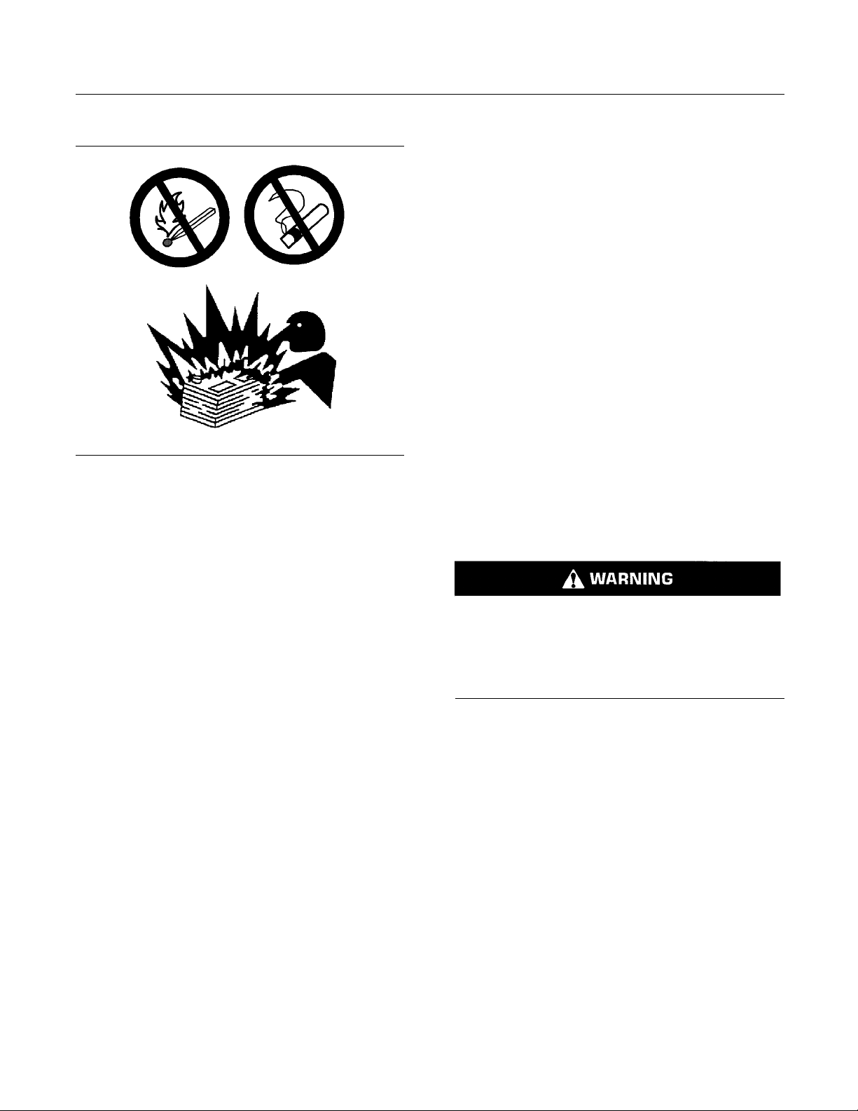
Illustration 7
General
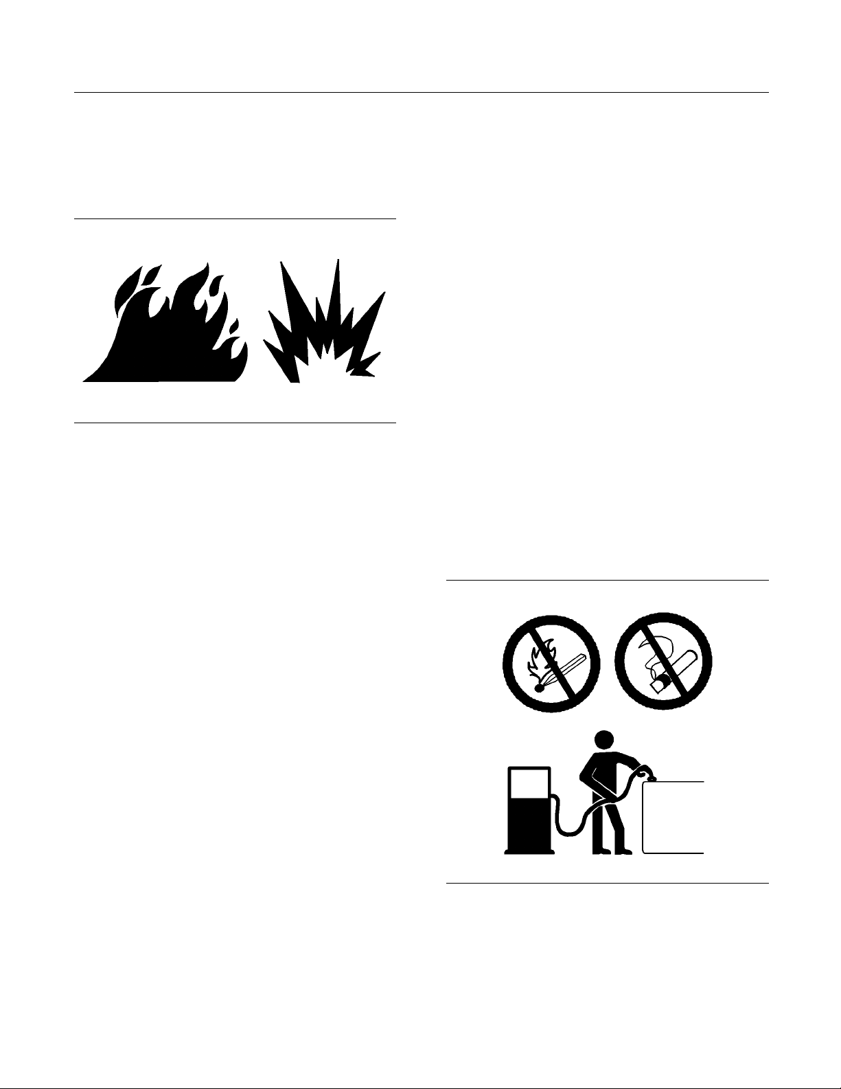
All fuels, most lubricants, and some coolant mixtures
are flammable.
To minimize the risk of fire or explosion, Prentice
recommends the following actions.
g00704000
Keep shields in
protect hot exhaust components from oil spray or fuel
spray in case of a break in a line, in a hose, or in a
seal. Exhaust
Do not weld or flame cut on tanks or lines that contain
flammable flui
purge the lines and tanks. Then clean the lines and
tanks with a nonflammable solvent prior to welding
or flame cutt
properly grounded in order to avoid unwanted arcs.
Dust that is
hoods or fenders may be flammable and/or explosive.
Repair such components in a well ventilated area
away from o
Personal Protection Equipment (PPE).
Inspect al
Replace damaged lines and hoses. The lines and
the hoses should have adequate support and secure
clamps. T
torque. Damage to the protective cover or insulation
may provide fuel for fires.
Store fuels and lubricants in properly marked
containers away from unauthorized personnel. Store
oily rag
containers. Do not smoke in areas that are used for
storing flammable materials.
sandflammable materials in protective
place. Exhaust shields (if equipped)
shields must be installed correctly.
ds or flammable material. Empty and
ing. Ensure that the components are
generated from repairing nonmetallic
pen flames or sparks. Use suitable
l lines and hoses for wear or deterioration.
ighten all connections to the recommended
Always perform a Walk-Around Inspection, which
may help you identify a fire hazard. Do not operate
a machine when a fire hazard exists. Contact your
Prentice dealer for service.
Understand the use of the primary exit and alternative
exit on the machine. Refer to Operation and
Maintenance Manual, “Alternative Exit”.
Do not operate a machine with a fluid leak. Repair
leaks and clean up fluids before resuming machine
operation. Fluids that are leaking or spilled onto hot
surfaces or onto electrical components can cause a
fire. A fire may cause personal injury or death.
Remove flammable material such as leaves,
twigs, papers, trash, and so on. These items may
accumulate in the engine compartment or around
other hot areas and hot parts on the machine.
Keep the access doors to major machine
compartments closed and access doors in working
conditioninordertopermittheuseoffire suppression
equipment, in case a fire should occur.
Clean all accumulations of flammable materials such
as fuel, oil, and debris from the machine.
Illustration 8
Usecautionwhenyouarefuelingamachine.Donot
smoke while you are fueling a machine. Do not fuel
a machine near open flames or sparks. Always stop
the engine before fueling. Fill the fuel tank outdoors.
Properly clean areas of spillage.
g00704059
Do not operate the machine near any flame.
Never store flammable fluids in the operator
compartment of the machine.
Page 13
SEBU9062 13
Safety Section
Fire Prevention and Explosion Prevention
Battery and Battery Cables
Illustration 9
Prentice recommends the following in order to
minimize the risk of fire or an explosion related to
the battery.
g02298225
Discoloration
•
Cuts on the insulation of the cable
•
Fouling
•
Corroded ter
•
terminals
Replace dam
any related parts. Eliminate any fouling, which may
have caused insulation failure or related component
damage or we
reinstalled correctly.
An exposed
a short to ground if the exposed area comes into
contact with a grounded surface. A battery cable
short prod
may be a fire hazard.
An expose
battery and the disconnect switch may cause the
disconnect switch to be bypassed if the exposed area
comes int
may result in an unsafe condition for servicing the
machine. Repair components or replace components
before s
minals, damaged terminals, and loose
aged battery cable(s) and replace
ar. Ensure that all components are
wire on the battery cable may cause
uces heat from the battery current, which
d wire on the ground cable between the
o contact with a grounded surface. This
ervicing the machine.
Do not operate a machine if battery cables or related
parts show signs of wear or damage. Contact your
Prentice dealer for service.
Follow safe procedures for engine starting with
jump-start cables. Improper jumper cable connections
can cause an explosion that may result in injury.
Refer to Operation and Maintenance Manual,
“Engine Starting with Jump Start Cables” for specific
instructions.
Do not charge a frozen battery. This may cause an
explosion.
Gases from a battery can explode. Keep any open
flames or sparks away from the top of a battery. Do
not smoke in battery charging areas.
Never check the battery charge by placing a metal
object across the terminal posts. Use a voltmeter in
order to check the battery charge.
Daily inspect battery cables that are in areas that
are visible. Inspect cables, clips, straps, and other
restraints for damage. Replace any damaged parts.
Check for signs of the following, which can occur
over time due to use and environmental factors:
Fraying
•
Abrasion
•
Cracking
•
Fire on a machine can result in personal injury
or death. Exposed battery cables that come into
contac
fires. Replace cables and related parts that show
signs of wear or damage. Contact your Prentice
deale
Wiri
Check electrical wires daily. If any of the following
cond
the machine.
•
•
•
•
•
•
Ma
are reinstalled correctly. This will help to prevent
vibration, rubbing against other parts, and excessive
h
t with a grounded connection can result in
r.
ng
itions exist, replace parts before you operate
ing
Fray
Signs of abrasion or wear
Cracking
scoloration
Di
Cuts on insulation
Other damage
ke sure that all clamps, guards, clips, and straps
eat during machine operation.
Page 14
14 SEBU9062
Safety Section
Fire Prevention and Explosion Prevention
Attaching elec
contain flammable fl uids or combustible fluids should
be avoided.
Consult your Prentice dealer for repair or for
replacement parts.
Keep wiring and electrical connections free of debris.
trical wiring to hoses and tubes that
Lines, Tubes, and Hoses
Do not bend h
high-pressure lines. Do not install any lines that
are bent or damaged. Use the appropriate backup
wrenches in
recommended torque.
igh-pressure lines. Do not strike
order to tighten all connections to the
Make sure that a
are installed correctly. During machine operation, this
will help to prevent vibration, rubbing against other
parts, excess
hoses.
Do not operat
exists. Repair any lines that are corroded, loose, or
damaged. Leaks may provide fuel for fires. Consult
your Prenti
parts. Use genuine Prentice parts or the equivalent,
for capabilities of both the pressure limit and
temperatur
ll clamps, guards, and heat shields
ive heat, and failure of lines, tubes, and
eamachinewhenafire hazard
ce dealer for repair or for replacement
e limit.
Ether
Ether (if equipped) is commonly used in cold-weather
applicati
Follow the correct cold engine starting procedures.
Refer to t
Manual with the label “Engine Starting”.
Do not spr
machine is equipped with a thermal starting aid for
cold weather starting.
ons. Ether is flammable and poisonous.
he section in the Operation and Maintenance
ay ether manually into an engine if the
600
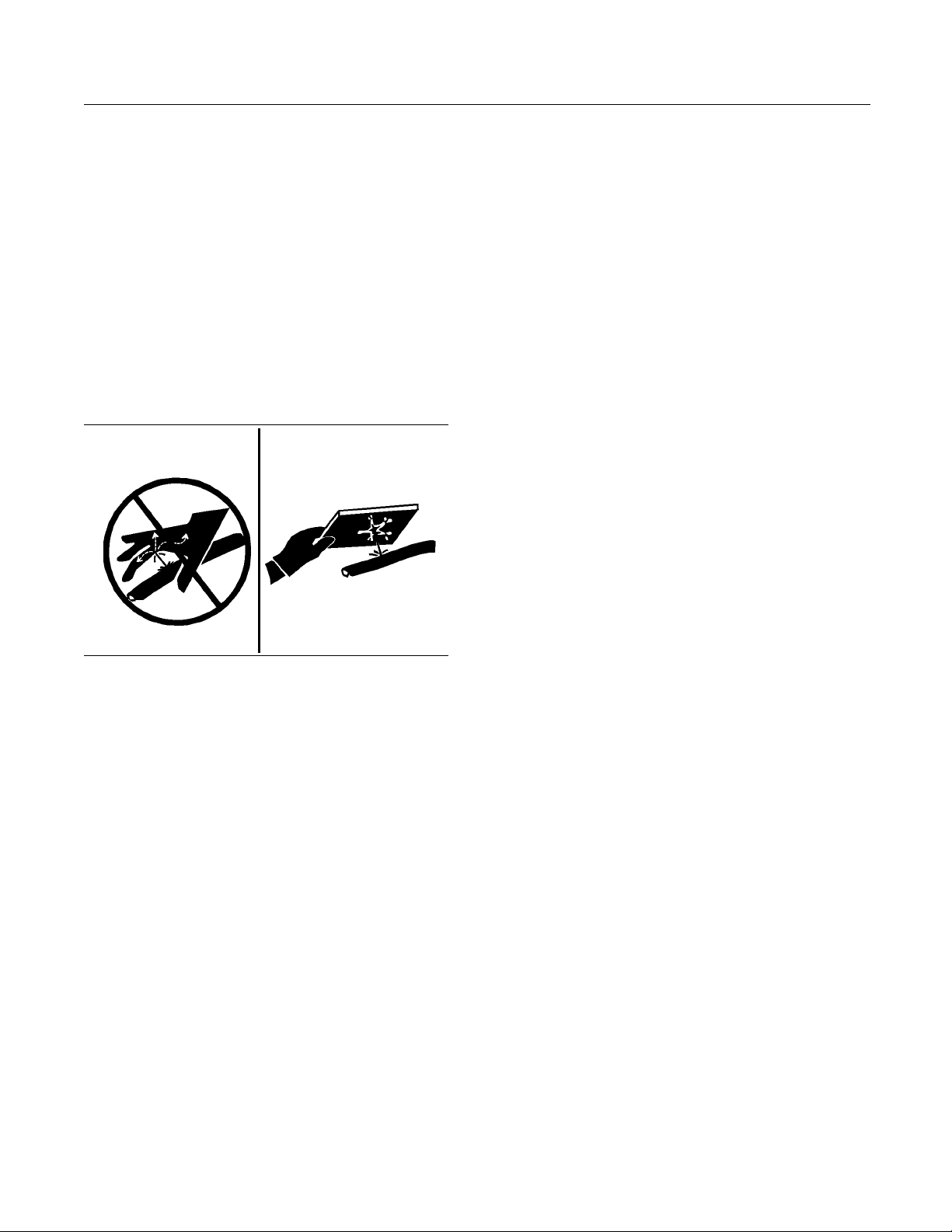
Illustration 10
Check lines, tubes, and hoses carefully. Wear
Personal Protection Equipment (PPE) in order to
for leaks. Always use a board or cardboard
check
when you check for a leak. Leaking fluid that is under
pressure can penetrate body tissue. Fluid penetration
ause serious injury and possible death. A pin
can c
hole leak can cause severe injury. If fluid is injected
into your skin, you must get treatment immediately.
treatment from a doctor that is familiar with this
Seek
type of injury.
lace the affected parts if any of the following
Rep
conditions are present:
fittings are damaged or leaking.
End
•
Outer coverings are chafed or cut.
•
Wires are exposed.
•
ter coverings are swelling or ballooning.
Ou
•
Flexible parts of the hoses are kinked.
•
g00687
Use ether in well ventilated areas. Do not smoke
while you are replacing an ether cylinder or while you
are usin
Do not store ether cylinders in living areas or in the
operat
ether cylinders in direct sunlight or in temperatures
above 49° C (120.2° F). Keep ether cylinders away
from o
Dispose of used ether cylinders properly. Do not
punct
away from unauthorized personnel.
ganetherspray.
or compartment of a machine. Do not store
pen flames or sparks.
ure an ether cylinder. Keep ether cylinders
Fire Extinguisher
additional safety measure, keep a fire
As an
extinguisher on the machine.
miliar with the operation of the fire extinguisher.
Be fa
Inspect the fire extinguisher and service the fire
extinguisher regularly. Follow the recommendations
he instruction plate.
on t
Consider installation of an aftermarket Fire
pression System, if the application and working
Sup
conditions warrant the installation.
Outer covers have exposed embedded armoring.
•
nd fittings are displaced.
E
•
Page 15

SEBU9062 15
Safety Section
Electrical Storm Injury Prevention
i01122596
Electrical Storm Injury
Prevention
SMCS Code: 6320
When lightning is striking in the vicinity of the
machine, the operator should never attempt the
following p
Mount the machine.
•
Dismount the machine.
•
If you are i
storm, stay in the operator's station. If you are on the
ground during an electrical storm, stay away from
the vicini
rocedures:
n the operator's station during an electrical
ty of the machine.
i01933657
Before Operation
SMCS Code: 6320
Clear all personnel from the area.
Clear all obstacles that are in the path of the machine.
Beware of hazards such as wires, ditches, etc.
Do not allow rid
machine has the following equipment:
additional se
•
additional seat belt
•
Rollover Protective Structure (ROPS)
•
Never use th
Report any needed repairs that were noted during
operation.
Carry attachments close to the ground, approximately
40 cm (15 in
go close to the edge of a cliff, an excavation, or an
overhang.
If the machine begins to sideslip, perform the
following procedure:
Discard the load.
•
Turn the m
•
Be careful to avoid any condition which could lead
ng. Tipping can occur when you work on
to tippi
hills, banks and slopes. Also, tipping can occur
when you cross ditches, ridges or other unexpected
obstruc
tions.
ers on the machine unless the
at
e work tool for a work platform.
ches) higher than ground level. Do not
achine downhill.
Whenever you are working around this product,
always wear: a hard hat, protective glasses, and
protective shoes. Whenever you are working around
this product, always wear the protective equipment
that is required by the conditions of the job site.
Refer to the Operation and Maintenance Manual,
“Daily Inspection” for more information on inspecting
the work tool before use.
i03634865
Operation
SMCS Code: 6320
Only operate the machine while you are in a seat.
The seat belt must be fastened while you operate the
machine. Only operate the controls while the engine
is running.
Check for proper operation of all controls and
protective devices while you operate the machine
slowly in an open area.
Before you move the machine, make sure that no
one will be endangered.
Whenever it is possible, operate the machine up the
slopes
machine across the slope, when possible.
Keep t
machine beyond capacity.
Be sur
adequate.
Conn
only.
Neve
to straddle a wire cable.
Whe
sure that no personnel are between the machine
and trailing equipment. Block the hitch of the trailing
equ
drawbar.
Kn
Always keep the Rollover Protective Structure
(R
and down the slopes. Avoid operating the
he machine under control. Do not overload the
e that the towing eyes and towing devices are
ect trailing equipment to a drawbar or to a hitch
r straddle a wire cable or allow other personnel
n you maneuver to connect the equipment, make
ipment in order to align the equipment with the
ow the maximum dimensions of your machine.
OPS) installed during machine operation.
Page 16

16 SEBU9062
Safety Section
Work Tools
i01908027
Work Tools
SMCS Code: 6320
Only use work t
authorized dealer for use on your machine.
If you are in d
particular work tool with your machine, consult your
authorized dealer.
Make sure that all necessary guarding is in place on
the host machine and on the work tool.
Keep all windows and doors closed on the host
machine. Always wear protective glasses. Always
wear the pr
in the work tool's operation manual. Wear any other
protective equipment that is required for the operating
environm
To prevent personnel from being struck by flying
objects,
area.
While yo
testing, or any adjustments to the work tool stay
clear of the following areas: cutting edges, pinching
surface
ensure that all personnel are out of the work
s, and crushing surfaces.
ools that are recommended by your
oubt about the compatibility of a
otective equipment that is recommended
ent.
u are performing any maintenance, any
Deactivation of the hydraulic controls does not
prevent the blade, boom swing, or auxiliary circuit
functions from moving under gravity or other external forces. Gravity or other external forces can
move the blade, boom swing, or auxiliary circuit
functions suddenly if a hydraulic control lever is
moved.
Personal injury or death may occur from sudden
machine movement.
6. Turn the engine start switch to the OFF position
and remove the key.
7. Turn the battery disconnect switch to the OFF
position. If the machine will not be operated for
an extended period, remove the key in order to
avoid battery discharge that may be caused by a
battery short circuit, by the current draw via certain
components, or by vandalism.
i04444189
Parking
SMCS Code: 6320
1. Park the machine on a level surface. If you must
park the machine on a downgrade, block the tires
or chock the tracks of the machine.
2. Apply the service brake in order to stop the
machine. Move the direction control switch to
NEUTRAL.
3. Engage the parking brake.
4. Lower all attachments to the ground. Make sure
that all attachments are in the recommended
servicing position before servicing the machine.
5. Move the hydraulic lockout control to the
LOCKED position. The hydraulic system remains
pressurized if the accumulator is charged. This
conditionistrueevenwhentheengineisnot
running. This pressure should decrease in a short
time (approximately 1 minute). While the hydraulic
system maintains a charge, the machine controls
remain functional.
Page 17
SEBU9062 17
Product Information Section
General Information
Product Information
Section
General Information
i04838149
Specifications
SMCS Code: 6320; 6700
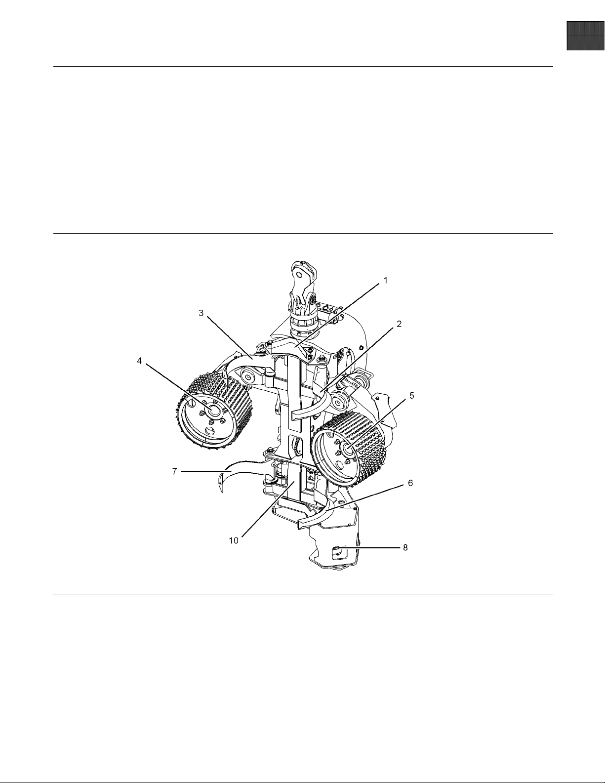
Illustration 11
PE44 H arvester Head
(1) Upper fixed knife, (2) Upper left delimbing knife, (3) Upper right delimbing knife, (4) Right feed roller, (5) Left feed roller, (6) Lower left
delimbing knife, (7) Lower right delimbing knife, (8) Saw motor, (9) Saw bar and saw chain, , and (10) Frame
g02970798
Page 18

18 SEBU9062
Product Information Section
General Information
Table 1
PE44 Harvester
Weight
Width (arms closed) 1321 mm (52 inch)
Width (arms open) 1820 mm (73 inch)
Height 1760 mm (69 inch) Maximum Roller Opening 620 mm (24.4 inch)
Main Saw - Bar Pitch / Type 0.404 TopDelimbKnife Fixed
Main Saw - Bar Length 750 mm (29.5 inch) Delimb Arms 4
Main Saw - Maximum
Diameter Cut
Main Saw - Maximum
Chain Speed
Chain Tensioning
Chain Oil Tank Capacity 31.7L(8.4USgal)
Rotator Rotation -
NonContinuous
Hydraulic Flow
Requirement Minimum
Feed Rollers 2 Feed Roller Motors 2
1378 kg (3037 lb) Motor Size
650 mm (25.5 inch) Delimb Pressure Proportional
43 m/sec (130 fps)
auto
360º
184 L/min (48 US gpm) Electrical System Voltage 24
Head
Maximum Feed Speed
(with std. motor)
Maximum Feed Force,
gross
Maximum Upper Knife
Opening
Maximum Lower Knife
Opening
Minimum Full Coverage
Delimb Diameter
Hydraulic Pressure
Requirement Maximum
780 cc
5 m/sec (16.5 ft/sec)
18.2 kN (4094 lb)
605 mm (23.8 inch)
706 mm (27.8inch)
35 mm (1.3 inch)
250 bar (3620 psi)
Intended Use
The Harvester Head is a highly effective head that
is designed for felling, delimbing, and cross cutting
trees. The Harvester Heads can be mounted on a
Harvester, Forest Machine (FM), or on an Excavator.
Power is supplied to the Harvester Head through the
base carriers hydraulic system.
Page 19
SEBU9062 19
Product Information Section
Identification Information
Identification Information
i04838210
Plate Locations and Film
Locations
SMCS Code: 6320
Serial Number
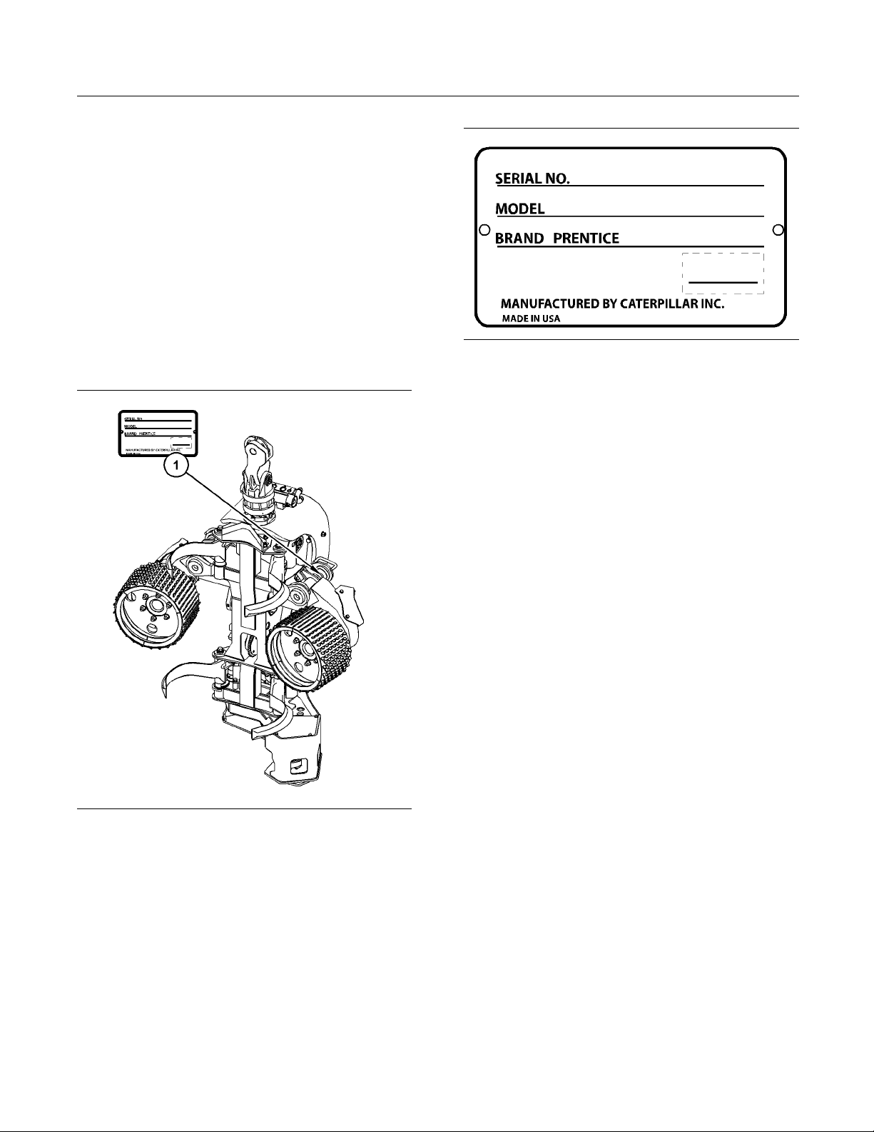
Prentice work tools are identified with serial numbers.
The serial number plate (1) is located on the right side
of the harvester head near the middle of the frame.
Illustration 13
(1) Serial number plate
For quick reference, record the identification numbers
in the spaces that are provided below.
Serial Number of the Work Tool
Model Number______________________________________________
_________________________
g02977916
Illustration 12
(1) Serial number plate location
g02977896
Page 20

20 SEBU9062
Operation Section
Operation
Operation Section
Operation
i04448298
Daily Inspection
SMCS Code: 1000; 3030; 6319; 6461; 6700-040;
6700; 6700-KH; 7000; 7615
Personal injury or death can result from improperly checking for a leak.
Always use a board or cardboard when checking
for a leak. Escaping air or fluid under pressure,
even a pi
sue causing serious injury, and possible dea th.
If fluid
immediately by a doctor familiar with this type of
injury.
Accumulatedgreaseandoilonaworktoolisafire
hazard.
n-hole size leak, can penetrate body tis-
is injected into your skin, it must be treated
NOTICE
6. Check the safet
messages when the safety messages are
damaged. Replace the safety messages when
you cannot rea
the safety messages when the safety messages
are missing.
7. Daily, perform all maintenance procedures that
are applicable to your work tool. Refer to ,
“Maintenan
information.
Perform all
service.
repairs before the work tool is put into
y messages. Replace the safety
d the safety messages. Replace
ce Interval Schedule” for additional
i04838271
Operation
SMCS Code:
7008; 7220; 7606
Note: The
wheel harvester and the track machine arrangements
are different. The machines use different controllers
and cont
Reference: For more information about the control
unit, re
fer to Systems Operation.
Operat
6129; 6461; 6700; 6700-KH; 7000;
operations of the harvester head on the
rol systems.
ing the Harvester Head
Remove debris with steam cleaning or high pressure
water at any time a significant quantity of oil is spilled
on the work tool.
For the maximum service life of the work tool, make
a thorough walk-around inspection before you mount
the machine and before you start the engine.
1. Inspect the harvester head for wear and damage
to individual components. Tighten loose bolts.
Remove any debris. Repair any damaged parts or
replace any damaged parts.
2. Inspect the condition of the attachments and the
condition of the hydraulic components. Repair any
damaged parts or replace any damaged parts.
Repair any leaks.
3. Check the saw bar and saw chain.
4. Check the oil level in the lubricating oil tank for
the saw chain.
5. Grease the fittings that need servicing on a daily
basis.
Positioning
A typical working cycle begins with the harvester
head in the TILT UP position. The roller arms and
limbing knives open. The saw is in the HOME
the de
position. The harvester head is positioned to the tree
with the boom so that the trunk comes between the
and lower knives and the feed rollers.
upper
Position the harvester head on the tree. Grip the
with the knives. Press the control button for
tree
the harvester head close inside the cab. When the
control system receives the signal from the button,
wo upper knives and the two lower knives will
the t
close. After a delay, the feed roller arms will close
against the tree.
The harvester head now has a firm grip on the tree.
The harvester head is ready for the actual felling of
tree.
the
Felling a Tree
Beforeyoucutdownthetree,planthefelling
operation completely. Preplanning allows the tree to
felled in the desired direction.
be
Page 21

SEBU9062 21
Operation Section
Operation
Consider the di
tree. Consider the lean of the tree before you fell a
tree.
The actual cutting of the tree from the stump is done
by a hydraulic saw in the harvester head. Press the
saw button in
motor will start to rotate and the saw bar will begin
moving toward the tree. Keep the button depressed
in order to c
The next step of the felling process will establish
conditions
Fell the tree in a direction that is easy to feed through
the delimb
rection of the wind, when you fell a
order to activate the saw. The saw
ontinue the process.
for delimbing and for cross cutting the tree.
ing/debarking knives.
Processing
Once the tree is felled, the processing begins.
Processing the tree means that the tree is delimbed
and/or de
lengths.
Delimbi
tree. Delimbing is achieved via the feed rollers that
pull the tree through the delimbing knives. As the tree
is fed th
log is measured by the feed rollers. This length is
displayed in the cab.
barked and the tree is cut to the desired
ng is the removing of the branches from the
rough the harvester head, the length of the
6. Place the cut lo
processed.
7. Avoid cutting
from the next trees on top of the pile of the
processed logs. Cutting off branches makes
extracting t
When processing of the tree is finished, and only the
top of the tr
the harvester head. Resetting prepares the harvester
head for the next tree. Press the ALL OPEN button
in order to o
knives, and the feed rollers. The tree will drop out of
the harvester head and the harvester head will tilt up.
Note: By programming the computer, a number
of automatic functions can be activated. The log
canbecuta
automatically after the cross cuts. These functions
areexamplesthatcanbeprogrammedintothe
computer
Manual for the harvester head as well as the Systems
Operation for the control system, before you attempt
to work wi
ee remains in the harvester head, reset
. Study the Operation and Maintenance
th the harvester head.
gsinapileafterthetreeis
off branches or shedding the bark
he logs harder.
pen the delimbing knives, the bottom
utomatically and/or the feed can begin
The feed roller motors can be activated by pressing
the Forward Feed button.
Feeding via the forward feed button will stop when
the button is released.
Usethefollowingmethodinordertofeedtoapreset
length.
1. Press the start button. The forward feed starts
automatically. The feeding will continue until the
et length is reached.
pres
2. Preset feeding can be stopped by pressing the
ride button.
Over
3. The control system controls the speed of the feed
lers. The tree stops within a set tolerance. The
rol
tolerance is set in the computer when the lengths
are programmed.
4. The knives will close around the tree when the
length is within the setting tolerance.
5. The saw will cut the log when the desired length
is achieved. Cutting is done by pressing the
w button or can be achieved automatically
sa
depending on the computer selection for cross
cutting.
Page 22

22 SEBU9062
Maintenance Section
Maintenance Support
Maintenance Section
Maintenance Support
i01828834
Welding on Machines and
Engines with Electronic
Controls
SMCS Code: 1000; 6461; 6640; 6700; 6700-KH;
7000; 7220
Proper welding procedures are necessary in order
to avoid damage to the electronic controls and to
the bearings. The following steps should be followed
in order to weld on a machine or an engine with
electronic controls.
Note: Ifyouareweldingonaworktool,removethe
work tool from the host machine before welding.
1. Turn off the engine.
2. Turn the battery disconnect switch to the OFF
position. If there is no battery disconnect switch,
remove the negative battery cable at the battery.
3. Clamp the ground cable from the welder to the
component that will be welded. Place the clamp
ascloseaspossibletotheweld.Makesurethat
the electrical path from the ground cable to the
component does not go through any bearing. Use
this procedure in order to reduce the possibility of
damage to the following components:
Bearings of the drive train
•
Hydraulic components
•
Electrical components
•
Other components of the machine
•
NOTICE
Do NOT use electrical components (ECM or sensors)
electronic component grounding points for ground-
or
ing the welder.
rotect any wiring harnesses from the debris
4.P
which is created from welding. Protect any wiring
harnesses from the splatter which is created from
elding.
w
5. Use standard welding procedures in order to weld
the materials together.
Page 23

SEBU9062 23
Maintenance Section
Maintenance Interval Schedule
i04288469
Maintenance Interval Schedule
SMCS Code: 6320; 6700
Ensure that al
instructions are read and understood before any
operation or any maintenance procedures are
performed.
The user is responsible for the performance of
maintenanc
proper lubricants, fluids, filters, and the replacement
of components due to normal wear and aging. Failure
to adhere t
procedures may result in diminished performance of
the product and/or accelerated wear of components.
Use mileage, fuel consumption, service hours, or
calendar time, WHICH EVER OCCURS FIRST,
in order t
Products that operate in severe operating conditions
may require more frequent maintenance.
Note: Before each consecutive interval is performed,
all maintenance from the previous interval must be
perform
l safety information, warnings, and
e, including all adjustments, the use of
o proper maintenance intervals and
o determine the maintenance intervals.
ed.
Every 2000 Serv
Delimbing Knife Cylinder Bearing - Replace ......... 27
Delimbing Kni
Feed Roller Arm Cylinder Bearing - Replace ........ 28
Feed Roller Arm Cylinder Seal - Replace ............. 29
Every 3000 Se
Feed Roller Arm Pivot Pin - Replace .................... 30
Knife Pivot
Pin - Replace ...................................... 37
ice Hours
fe Cylinder Seal - Replace .............. 27
rvice Hours
Every 4000 Service Hours
Bail Cylind
Feed Roller Motor Seal - Replace ........................ 32
Hydraulic Rotator Motor Seals - Replace ............. 37
er and Mounting Bearings - Replace ... 24
When Required
Delimb
Harvester Head (Bolts) - Inspect .......................... 33
Saw Bar - Inspect ................................................. 38
Saw Cha
Saw Chain - Sharpen ............................................ 40
ing Knife Cutting Edges - Sharpen ............ 25
in - Remove/Install ................................. 39
Every 10 Service Hours or Daily
Delimbing Knife Cutting Edges - Inspect ............. 25
Feed Roller - Inspect ............................................ 28
Feed R
Harvester Head - Lubricate ................................... 35
Hydraulic Fittings - Inspect ................................... 36
Saw B
Saw Chain - Remove/Install ................................. 39
Saw Chain - Sharpen ............................................ 40
Spro
oller Cutting Edges - Inspect ..................... 31
ar - Inspect ................................................. 38
cket - Inspect ................................................. 41
Every 50 Service Hours or Weekly
vester Head (Bolts) - Inspect .......................... 34
Har
Every 250 Service Hours or Monthly
limbing Knife Cutting Edges - Sharpen ............ 25
De
Every 500 Service Hours
ed Roller Arm Stop - Replace ........................... 31
Fe
Page 24
24 SEBU9062
Maintenance Section
Bail Cylinder and Mounting Bearings - Replace
Bail Cylinder and Mounting
Bearings - Rep
SMCS Code: 5307
lace
i04839569
Turn the batter
•
position
Relieve the hy
•
by moving the joystick and control levers to
relieve pressure
Purge a ll air from the reservoir
•
Refer to the
of the host machine for additional information.
2. In order to r
assembly, remove Harvester Head .
y disconnect switch to the OFF
draulic pressure on all functions
Operation and Maintenance Manual
eplace pins and bushings in the bail
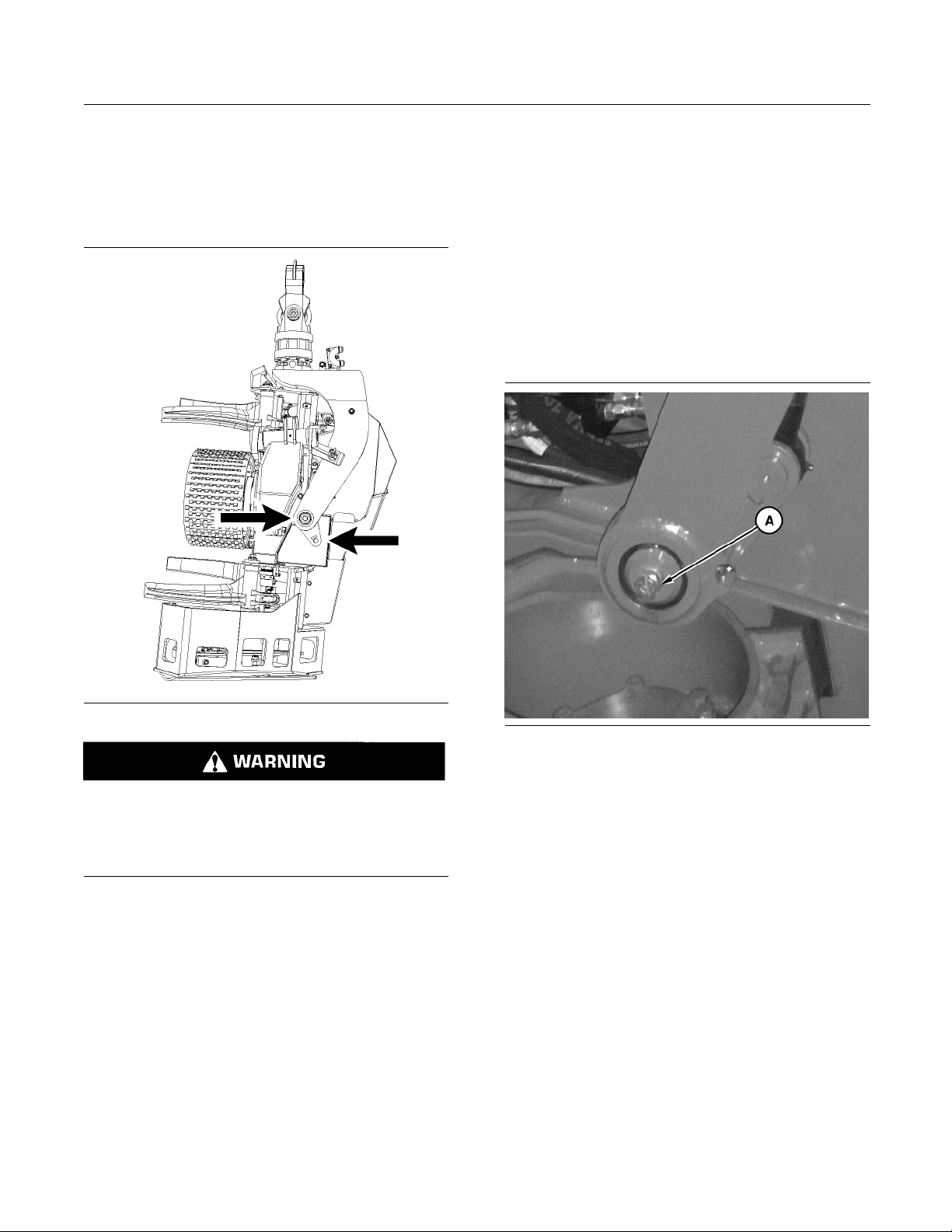
Illustration 14
Always perform service on the Harvester Head
from the side or the rear of the work tool.
Could cause serious injury or death from improperly servicing the Harvester Head.
1. Perform the following required steps before
performing any maintenance procedure:
Secure the Harvester Head in the upright
•
position with a chain
Lower the Harvester Head to the ground
•
If equipped, engage the parking brake on the
•
host machine
Stop the engine on the host machine. Remove
•
the engine start switch key before exiting the
machine
g02970477
Illustration 15
3. Remove nut and washer (A).
4. Remove bolt and spacer (B).
5. Remove pin assemblies.
g02977725
Page 25
SEBU9062 25
Maintenance Section
Delimbing Knife Cutting Edges - Inspect
Illustration 16
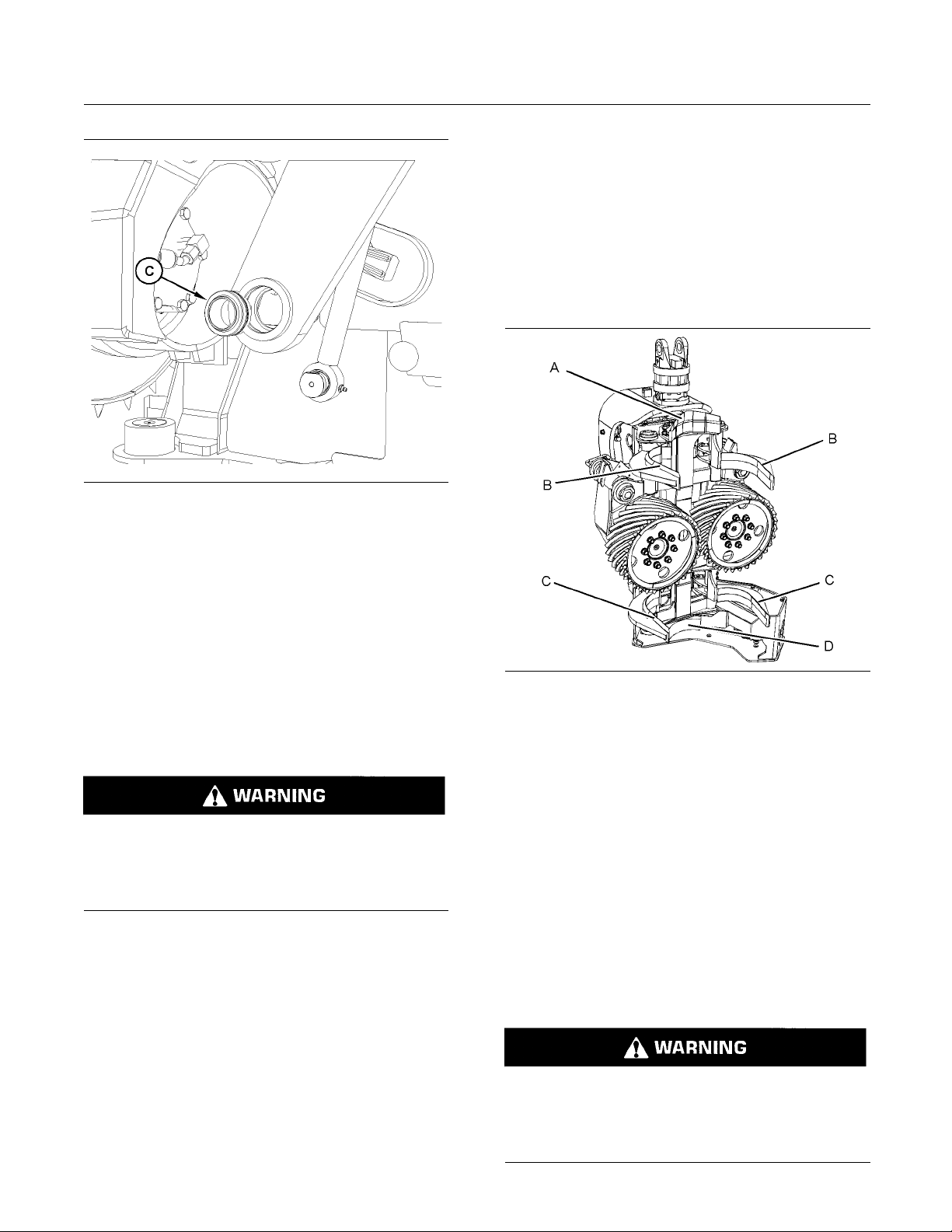
6. Remove bushings (C) .
7. Use tooling and install new bushing.
g02977742
Turn the batter
•
position
Relieve the hy
•
by moving the joystick and control levers to
relieve pressure
Purge a ll air from the reservoir
•
Refer to the
of the host machine for additional information.
y disconnect switch to the OFF
draulic pressure on all functions
Operation and Maintenance Manual
8. Replace Pin assemblies, retaining rings, spacers,
and hardware with new parts.
i04480310
Delimbing Kn ife Cutting Edges
- Inspect
SMCS Code: 6320-040-KNF
Always perform service on the Harvester Head
from the side or the rear of the work tool.
Could cause serious injury or death from improperly servicing the Harvester Head.
1. Perform the following required steps before
performing any maintenance procedure:
Secure the Harvester Head in the upright
•
position with a chain
Lower the Harvester Head to the ground
•
Illustration 17
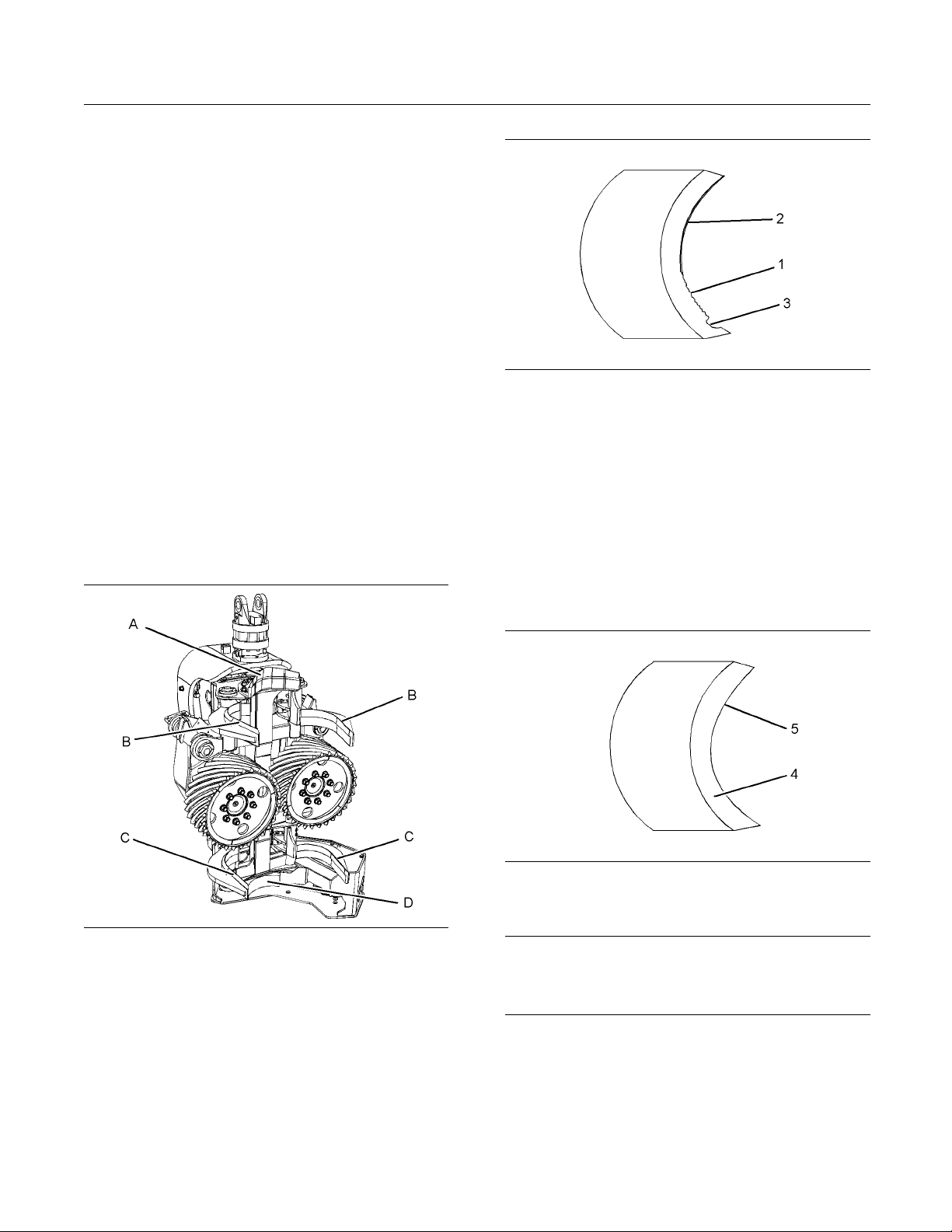
(A) Upper fixed knife
(B) Upper arm knife blades
(C) Lower arm knife blades
(D) Lower fixed knife
2. Inspect the upper fixed knife (A), upper arm knife
blades (B), lower arm knife blades (C), and lower
fixed knife (D), for nicked, gapped, or rolled edges.
3. If sharpening of the knife blades is required, refer
to , “Delimbing Knife Cutting Edges - Sharpen”.
g02660882
i04482529
Delimbing Knif e Cutting Edges
-Sharpen
SMCS Code: 6320-502-KNF
If equipped, engage the parking brake on the
•
host machine
Stop the engine on the host machine. Remove
•
the engine start switch key before exiting the
machine
Always perform service on the Harvester Head
from the side or the rear of the work tool.
Could cause serious injury or death from improperly servicing the Harvester Head.
Page 26
26 SEBU9062
Maintenance Section
Delimbing Knife Cutting Edges - Sharpen
1. Perform the fol
lowing required steps before
performing any maintenance procedure:
Secure the Har
•
vester Head in the upright
position with a chain
Lower the Har
•
If equipped, engage the parking brake on the
•
host machin
Stop the engine on the host machine. Remove
•
the engine s
vester Head to the ground
e
tart switch key before exiting the
machine
Turn the ba
•
ttery disconnect switch to the OFF
position
Relieve th
•
e hydraulic pressure on all functions
by moving the joystick and control levers to
relieve pressure
Purge all air from the reservoir
•
Refer to t
he Operation and Maintenance Manual
of the host machine for additional information.
Illustration 19
(1) Nicked
(2) Gapped
(3) Rolled
g02662177
3. Remove small nicks (1), gaps (2), and rolled (3)
edges with a 203 mm (8 inch) or 254 mm (10 inch)
flat mill file.
4. Sharpen all blades using the same technique as
required for an ax or for a bladed cutting tool.
The blades will wear thin from use and cause the
edges to roll. Rolled edges cause dull blades. The
blades should require sharpening once a month.
Illustration 18
(A) Upper fixed knife
(B) Upper arm knife blades
(C) Lower arm knife blades
(D) Lower fixed knife
g02660882
2. Sharpen the upper fixed knife (A), upper arm knife
blades (B), lower arm knife blades (C), and lower
fixed knife (D), to remove all nicks, gaps, and
rolled edges.
Illustration 20
Outside
(4)
Inside
(5)
g02662237
NOTICE
Do not sharpen knife blades unless necessary. Over
sharpening the knife blades will cause premature wear
and shorten the life of the knife blades.
5. When blades require sharpening, file the outside
(4) of the blade to a keen edge using the
recommended file. After a keen edge is filed on
the outside (4), touch up the inside (5) with the
file. Do not file heavily on the inside (5).
Page 27
SEBU9062 27
Maintenance Section
Delimbing Knife Cylinder Bearing - Replace
i04660429
Delimbing Kn ife Cylinder
Bearing - Repl
SMCS Code: 5362; 5554
Always perform service on the Harvester Head
from the side or the rear of the work tool.
Could cause serious injury or death from improperly servicing the Harvester Head.
ace
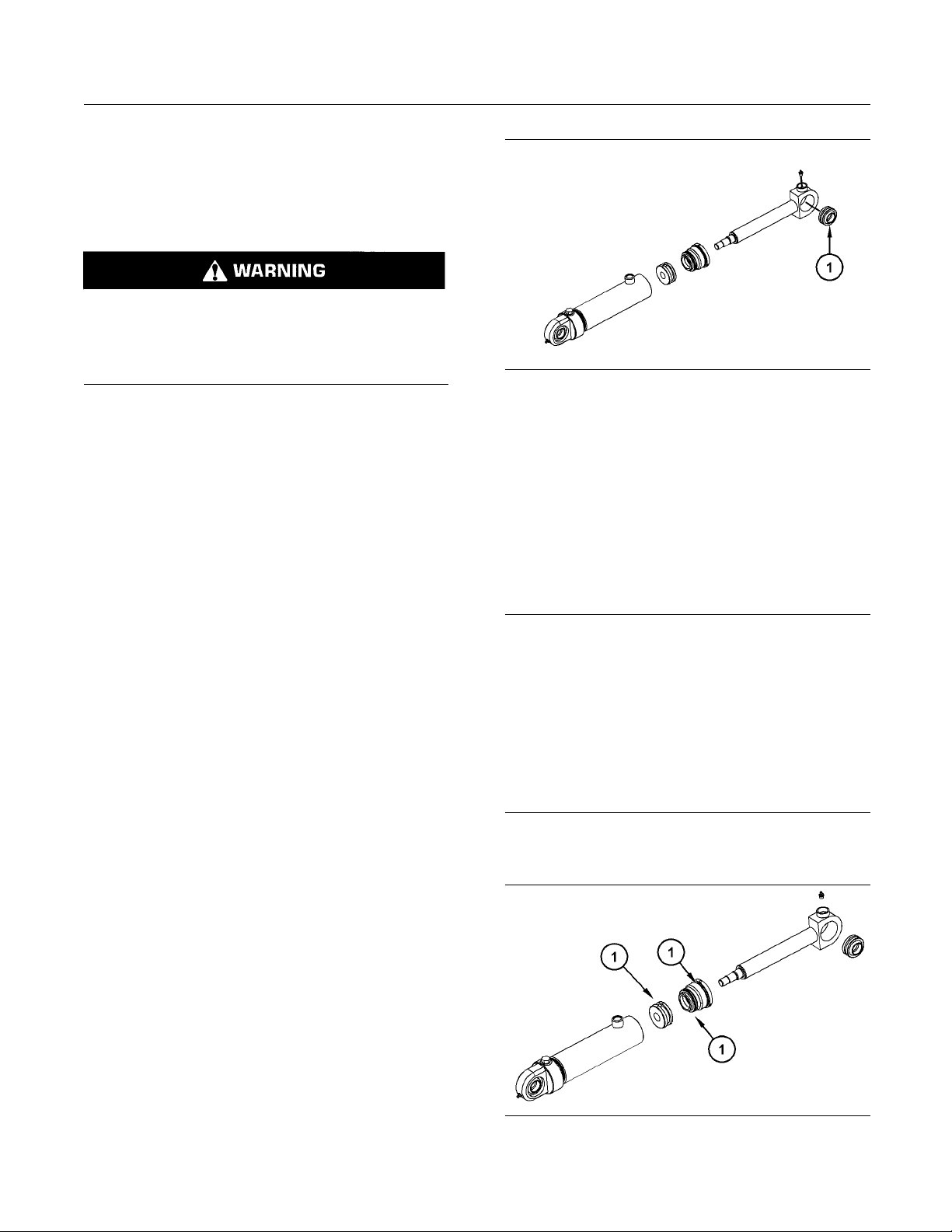
Illustration 21
g02799416
1. Perform the following required steps before
performing any maintenance procedure:
Secure the Harvester Head in the upright
•
position with a chain
Lower the Harvester Head to the ground
•
If equipped, engage the parking brake on the
•
host machine
Stop the engine on the host machine. Remove
•
the engine start switch key before exiting the
machine
Turn the battery disconnect switch to the OFF
•
position
Relieve the hydraulic pressure on all functions
•
by moving the joystick and control levers to
relieve pressure
Purge all air from the reservoir
•
Refer to the Operation and Maintenance Manual
of the host machine for additional information.
2. In order to replace bearings in the delimber knife
cylinder assembly, remove cylinder as described
in Disassembly and Assembly manual.
4. Remove bearing (1) .
5. Use tooling and install new bearing.
i04663890
Delimbi
ng K nife Cylinder Seal
- Replace
SMCS Co
Care must be taken to ensure that fluids are contained
during performance of inspection, maintenance, testing, adjusting and repair of the product. Be prepared
to collect the fluid with suitable containers before operating any compartment or disassembling any component containing fluids.
After collecting all fluids in suitable containers, dispose
of all fluids according to local regulations and mandates.
Note: Refer to Disassembly and Assembly manual
for delimber knife and cylinder removal procedure.
de: 5362; 5554
NOTICE
3. Remove pin assemblies.
Illustration 22
g02798857
Page 28
28 SEBU9062
Maintenance Section
Feed Roller - Inspect
Note: Cleanlin
assembly, clean all parts in cleaning fluid. Allow the
parts to air dry. Wiping in cloths or rags should not be
used to dry par
which may cause later trouble. Inspect all parts. If
any parts are worn or damaged, use new parts for
replacement
1. Lubricate sealing lips (1) and cylinder shaft with a
thin coveri
2. Reassemble cylinder as described in the
Disassembl
3. Install in reverse order of removal procedure.
ess is an important factor. Before
ts. Lint may be deposited on the parts
.
ng of the lubricant that is being sealed.
y and Assembly manual.
i04479610
Feed Roller - Inspect
(Motor)
SMCS Code: 6328-040-HHD
Always perform service on the Harvester Head
from the side or the rear of the work tool.
Could cause serious injury or death from improperly servicing the Harvester Head.
Illustration 23
2. Inspect the feed roller motors for leakage.
3. Repair or replace as needed.
Feed Roller Arm Cylinder
Bearing - Replace
g02659958
i04663949
1. Perform the following required steps before
performing any maintenance procedure:
Secure the Harvester Head in the upright
•
position with a chain
Lower the Harvester Head to the ground
•
uipped, engage the parking brake on the
If eq
•
host machine
p the engine on the host machine. Remove
Sto
•
the engine start switch key before exiting the
machine
Turn the battery disconnect switch to the OFF
•
position
Relieve the hydraulic pressure on all functions
•
by moving the joystick and control levers to
lieve pressure
re
Purge all air from the reservoir
•
Refer to the Operation and Maintenance Manual
of the host machine for additional information.
SMCS Code: 5362; 5572
Always perform service on the Harvester Head
from the side or the rear of the work tool.
Could cause serious injury or death from improperly servicing the Harvester Head.
1. Perform the following required steps before
performing any maintenance procedure:
Secure the Harvester Head in the upright
•
position with a chain
Lower the Harvester Head to the ground
•
If equipped, engage the parking brake on the
•
host machine
Stop the engine on the host machine. Remove
•
the engine start switch key before exiting the
machine
Turn the battery disconnect switch to the OFF
•
position
Page 29
SEBU9062 29
Maintenance Section
Feed Roller Arm Cylinder Seal - Replace
Relieve the hyd
•
by moving the joystick and control levers to
relieve pressure
Purge all air from the reservoir
•
Refer to the O
of the host machine for additional information.
2. In order to r
cylinder assembly, remove cylinder as described
in Disassembly and Assembly manual.
3. Remove pin assemblies.
raulic pressure on all functions
peration and Maintenance Manual
eplace bearings in the delimber knife
i04663953
Feed Rolle r Arm Cylinder Seal
- Replace
SMCS Code: 5362; 5572
NOTICE
Care must be taken to ensure that fluids are contained
during performance of inspection, maintenance, testing, adjusting and repair of the product. Be prepared
to collect the fluid with suitable containers before operating any compartment or disassembling any component containing fluids.
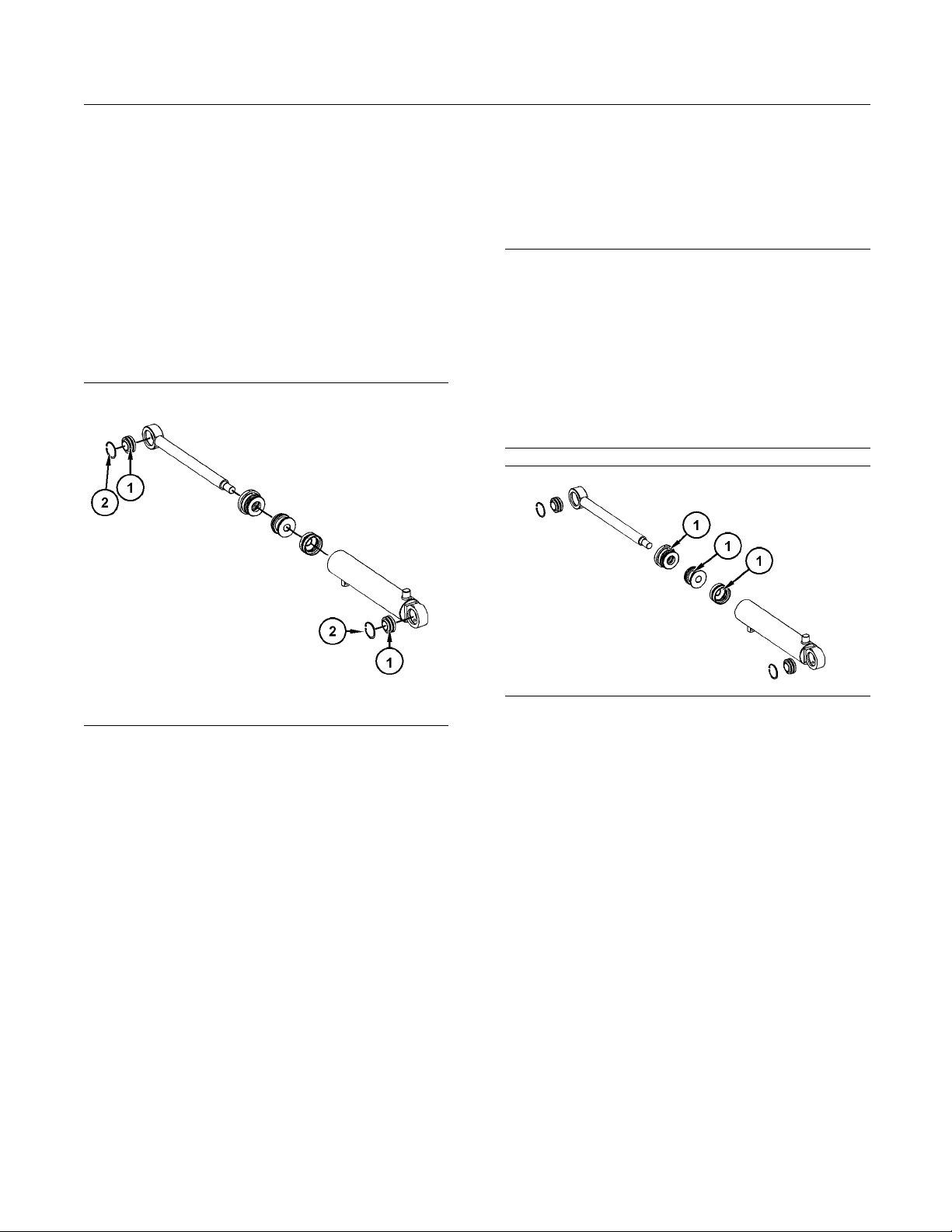
After collecting all fluids in suitable containers, dispose
of all fluids according to local regulations and mandates.
Illustration 24
4. Remove retaining ring(2) .
5. Remove bearing (1) .
6. Use tooling and install new bearing.
g02799436
Illustration 25
Note: Cleanliness is an important factor. Before
assembly, clean all parts in cleaning fluid. Allow the
parts to air dry. Wiping cloths or rags should not be
used to dry parts. Lint may be deposited on the parts
which may cause later trouble. Inspect all parts. If
any parts are worn or damaged, use new parts for
replacement.
Note: Lubricate all O-rings and seals with the
lubricant that is being sealed.
Replace all O-rings and seals (1) with new.
Reassemble cylinder as described in the Disassembly
and Assembly manual.
g02799151
Page 30
30 SEBU9062
Maintenance Section
Feed Roller Arm Pivot Pin - Replace
i04663990
Feed R oller Arm Pivot Pin Replace
SMCS Code: 6328; 6328-FRA
Illustration 26
g02796511
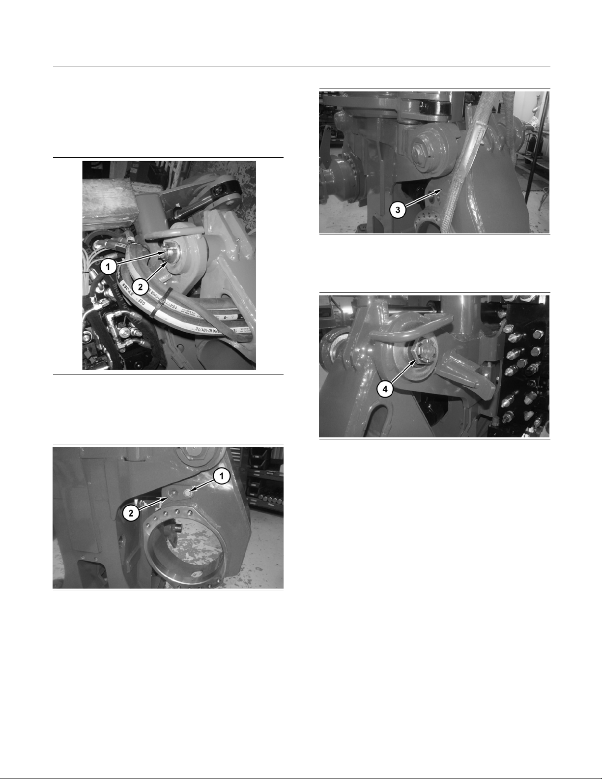
In order to replace the feed roller arm pivot pin.
Begin with the harvester head in the vertical position.
Support the frame in this position.
Illustration 28
g02435976
2. Attachasuitableliftingdevicetofeedrollerarm
(3).
Illustration 29
3. Remov
e nut (4).
g02436038
Remove pin.
Illustration 27
1. Remove bolt (1) and pin (2).
g02436064
Page 31
SEBU9062 31
Maintenance Section
Feed Roller Arm Stop - Replace
i04663955
Feed Roller Arm Stop - R eplace
SMCS Code: 6328; 6328-SQ; 6328-FRA
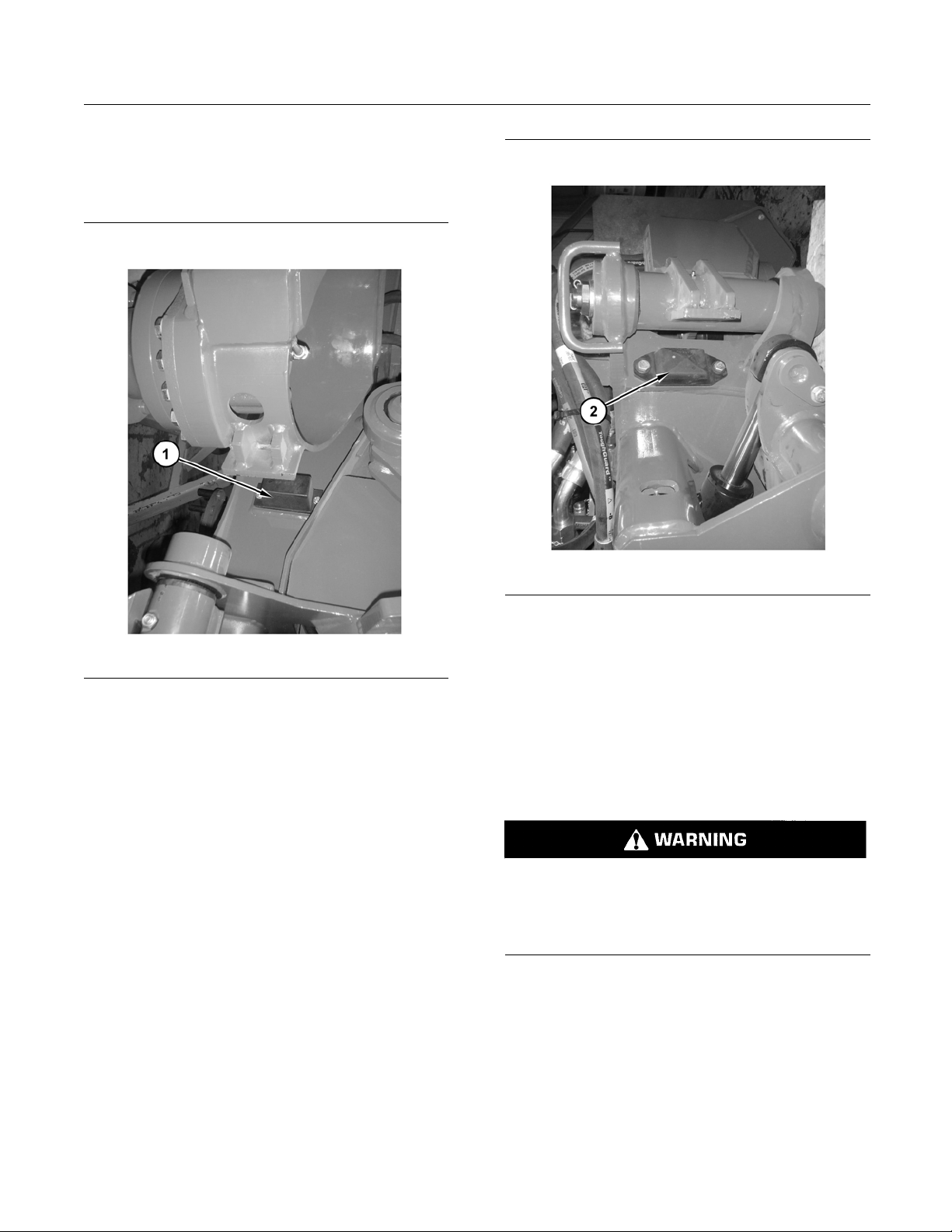
Illustration 30
Replace lower feed roller stop (1 ). Replace retaining
bolts and washers.
g02796374
Illustration 31
Replace
bolts and washers.
upper feed roller stop (2 ). Replace retaining
g02796373
i04841172
Feed Roller Cutting Edges Inspect
SMCS Code: 6328-040-HHD
Always perform service on the Harvester Head
from the side or the rear of the work tool.
Could cause serious injury or death from improperly servicing the Harvester Head.
1. Perform the following required steps before
performing any maintenance procedure:
Secure the Harvester Head in the upright
•
position with a chain
Lower the Harvester Head to the ground
•
equipped, engage the parking brake on the
If
•
host machine
Page 32
32 SEBU9062
Maintenance Section
Feed Roller Motor Seal - Replace
Stop the engine
•
on the host machine. Remove
the engine start switch key before exiting the
machine
Turn the battery disconnect switch to the OFF
•
position
Relieve the hydraulic pressure on all functions
•
by moving the joystick and control levers to
relieve pre
Purge all air from the reservoir
•
ssure
Refer to the Operation and Maintenance Manual
of the host machine for additional information.
Feed Roller Motor Seal Replace
SMCS Code: 5058; 5058-FRA; 6328
tion 33
Illustra
1. Remove O-ring seal (1).
i04663976
g02796594
Illustration 32
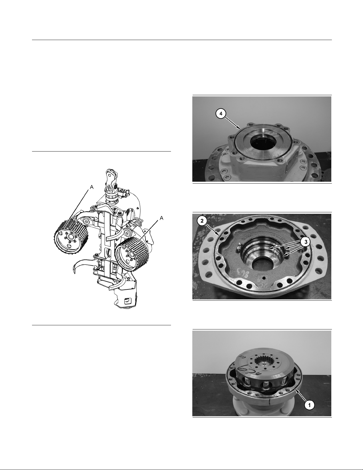
eed ro lle rs
(A) F
g02972101
2. Inspect the cutting edges on the feed rollers (A)
nicked, gapped, or rolled edges. Replace feed
for
rollers if necessary.
Illustration 34
2. Remove O-ring seal (2) and seals (3).
Illustration 35
emove O-ring seal (4).
3.R
g02796596
g02796614
Page 33
SEBU9062 33
Maintenance Section
Harvester Head (Bolts) - Inspect
Replace all O-r
ings and seals with new parts.
Harvester H ead (Bolts) Inspect
SMCS Code: 6320-040-BC
i04843429
Relieve the hyd
•
raulic pressure on all functions
by moving the joystick and control levers to
relieve pressure
Purge a ll air from the reservoir
•
Table 2
Check Torque Intervals
After
initial 1
hour of
operation
After
initial 3
hours of
operation
After 8
hours of
operatio
or daily
After 40
hours of
operation
or weekly
Refer to torque values listed below
Refer to torque values listed below
Refer to torque values listed below
n
Refer to torque values listed below
Illustration 36
g02974996
Always perform service on the Harvester Head
from the side or the rear of the work tool.
Could cause serious injury or death from improperly servicing the Harvester Head.
1. Perform the following required steps before
performing any maintenance procedure:
Secure the Harvester Head in the upright
•
position with a chain
Lower the Harvester Head to the ground
•
If equipped, engage the parking brake on the
•
host machine
Stop the engine on the host machine. Remove
•
the engine start switch key before exiting the
machine
Refer to the Operation and Maintenance Manual
of the host machine for additional information.
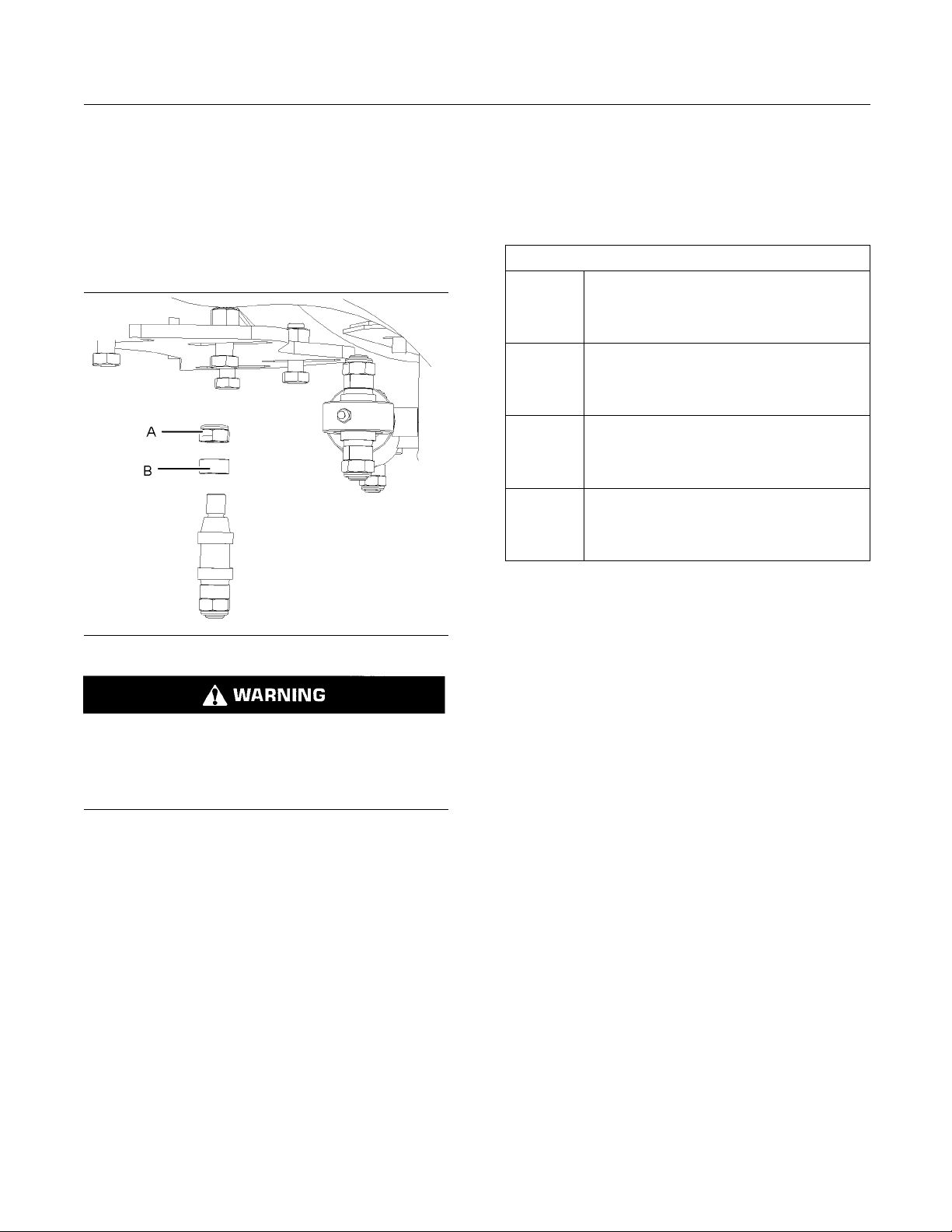
2. Inspect the expander pin tension washers (A).
Retorque to 125 N·m (192 lb ft).
3. Inspect the expander pin fastening hardware (B).
Retorque to 175 N·m (129 lb ft).
Reference: Refer to Specifications, SENR3130,
“Torque Specifications” for proper torque information.
Note: Lubricate the expansion sleeves before
insertion.
1. Insert expander pin into the bore.
2. Install expansion sleeves.
3. Hand tighten lock nut
4. Torque to required values.
Note: The tension washer should never contact the
pivot lug. Upon occurrence contact a Prentice dealer.
1. Lubricate expansion pin before operating machine.
Turn the battery disconnect switch to the OFF
•
position
Page 34
34 SEBU9062
Maintenance Section
Harvester Head (Bolts) - Inspect
i04841229
Harvester H ead (Bolts) Inspect
SMCS Code: 6320-040-BC
Illustration 37
s perform service on the Harvester Head
Alway
from the side or the rear of the work tool.
d cause serious injury or death from improp-
Coul
erly servicing the Harvester Head.
1. Perf
orm the following required steps before
performing any maintenance procedure:
ure the Harvester Head in the upright
Sec
•
position with a chain
er the Harvester Head to the ground
Low
•
If equipped, engage the parking brake on the
•
st machine
ho
Stop the engine on the host machine. Remove
•
e engine start switch key before exiting the
th
machine
g02974316
Turn the battery disconnect switch to the OFF
•
position
Relieve the hydraulic pressure on all functions
•
by moving the joystick and control levers to
relieve pressure
Purge a ll air from the reservoir
•
Refer to the Operation and Maintenance Manual
of the host machine for additional information.
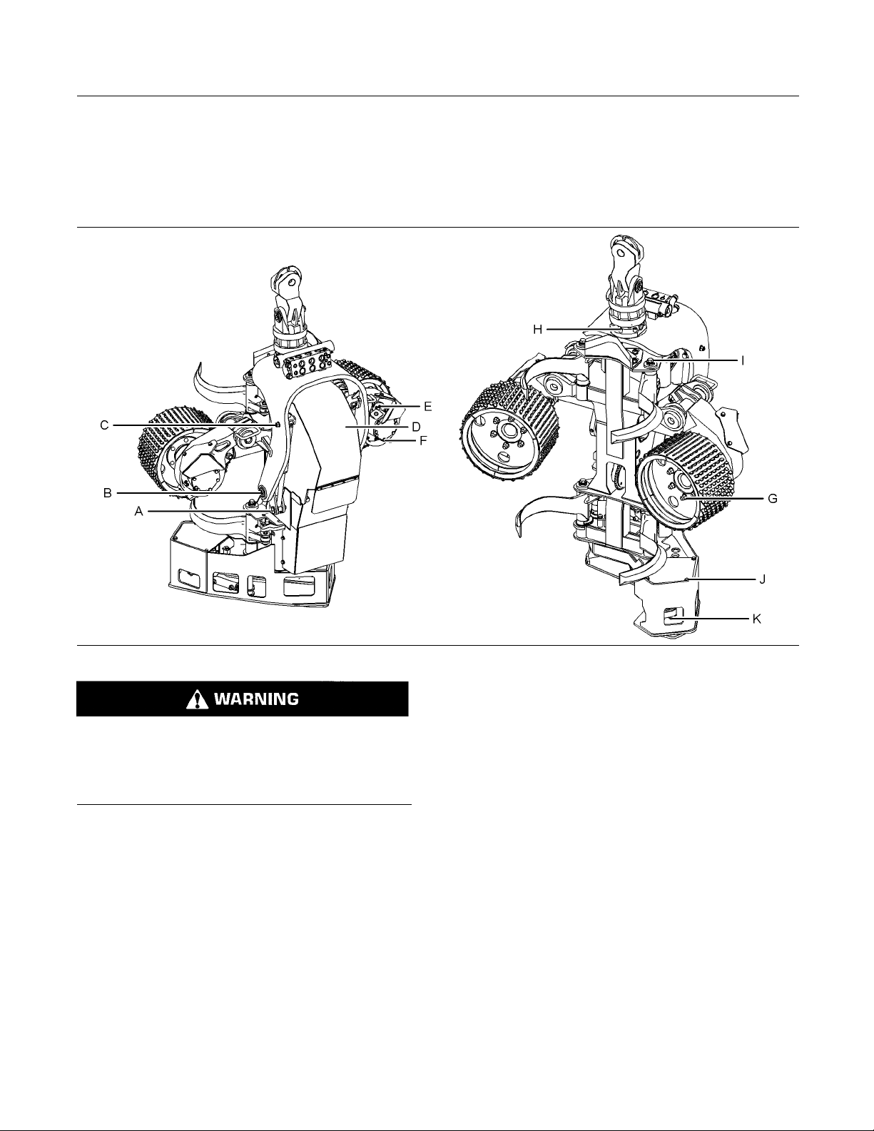
2. Inspect tilt frame cylinder lower mounting bolts
(A). Retorque to 240 ± 40 N·m (177 ± 30 lb ft).
3. Inspect tilt frame bearing mounting bolts (B).
Retorque to 240 ± 40 N·m (177 ± 30 lb ft).
4. Inspect tilt frame cylinder upper mounting bolts
(C). Retorque to 240 ± 40 N·m (177 ± 30 lb ft).
5. Inspect valve block mounting bolts (D). Retorque
to100±20N·m(74±15lbft).
Page 35
SEBU9062 35
Maintenance Section
Harvester Head - Lubricate
6. Inspect feed ro
100±20N·m(74±15lbft).
7. Inspect feed r
Retorque to 240 ± 40 N·m (177 ± 30 lb ft).
8. Inspect feed
to 240 ± 40 N·m (177 ± 30 lb ft).
9. Inspect rot
240 ± 40 N·m (177 ± 30 lb ft).
10. Inspect fixe
Retorque to 240 ± 40 N·m (177 ± 30 lb ft).
11. Inspect sa
to 100 ± 20 N·m (74 ± 15 lb ft).
12. Inspect sa
to28N·m(250lbin).
Referenc
“Torque Specifications” for proper torque information.
e: Refer to Specifications, SENR3130,
ller housing bolts (E). Retorque to
oller motor mounting bolts (F).
roller mounting bolts (G). Retorque
ator mounting bolts (H). Retorque to
d delimbing knife mounting bolts (I).
w cover mounting bolts (J). Retorque
w motor mounting bolts (K). Retorque
i04841309
Purge a ll air fr
•
Refer to the Operation and Maintenance Manual
of the host mac
When greasing lubrication fittings, if grease is not
forced out of the bushing ends with the recommended
shots of gre
grease is forced out. If grease cannot be forced out,
check for blocked grease passageways.
If the lubricated areas are dry at the end of a normal operating day, increase the frequency of the lubricating
of grease used in one lubrication period.
ase, increase the number of shots until
intervals rather than increasing the amount
om the reservoir
hine for additional information.
NOTICE
Harvest
SMCS Code: 6320-086
Always perform service on the Harvester Head
he side or the rear of the work tool.
from t
Could cause serious injury or death from improp-
servicing the Harvester Head.
erly
1. Perform the following required steps before
perf
Secure the Harvester Head in the upright
•
pos
Lower the Harvester Head to the ground
•
If equipped, engage the parking brake on the
•
host machine
Stop the engine on the host machine. Remove
•
the engine start switch key before exiting the
ma
er Head - Lub ricate
orming any maintenance procedure:
ition with a chain
chine
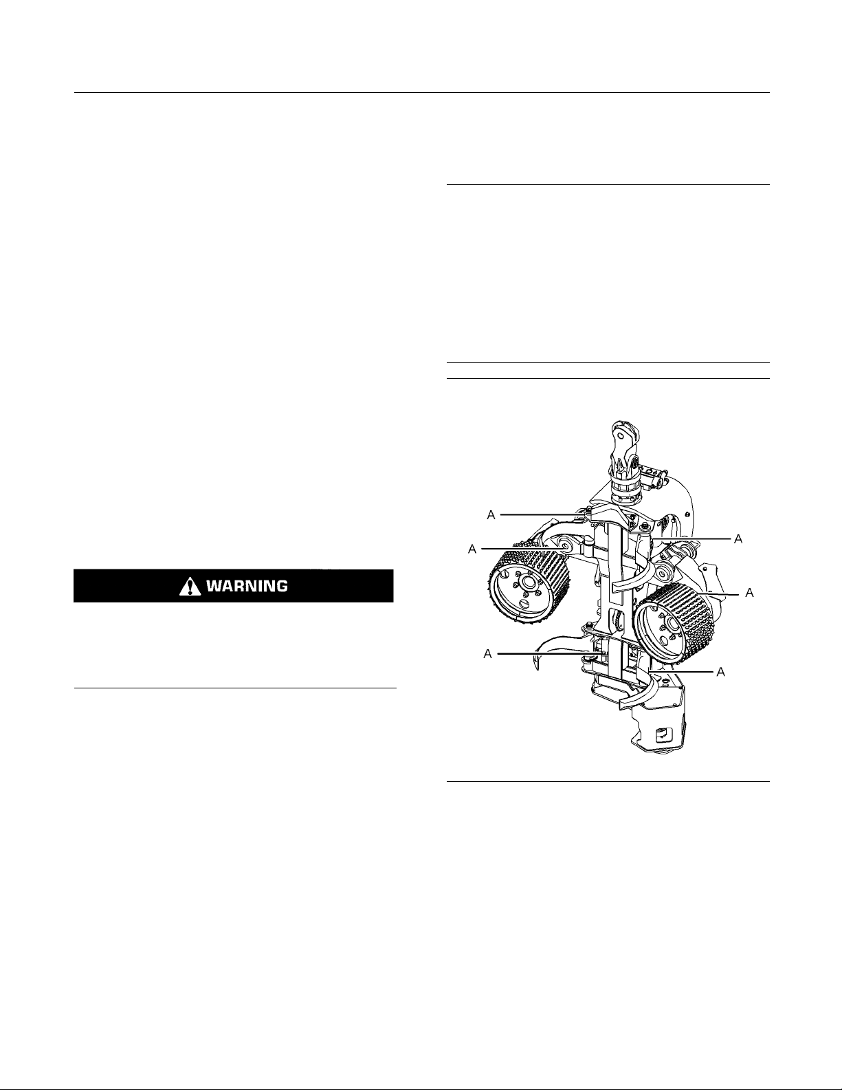
Illustration 38
Typical example of grease zerk locations. Some locations may no t
be visible. Grease all grease z erks daily.
2. Lubricate all cylinder bases (A) and rod ends
(A) grease zerks with grease. Grease zerks are
locatedonbothsidesoftheHarvesterHead.
g02977217
Turn the battery disconnect switch to the OFF
•
osition
p
Relieve the hydraulic pressure on all functions
•
y moving the joystick and control levers to
b
relieve pressure
Page 36
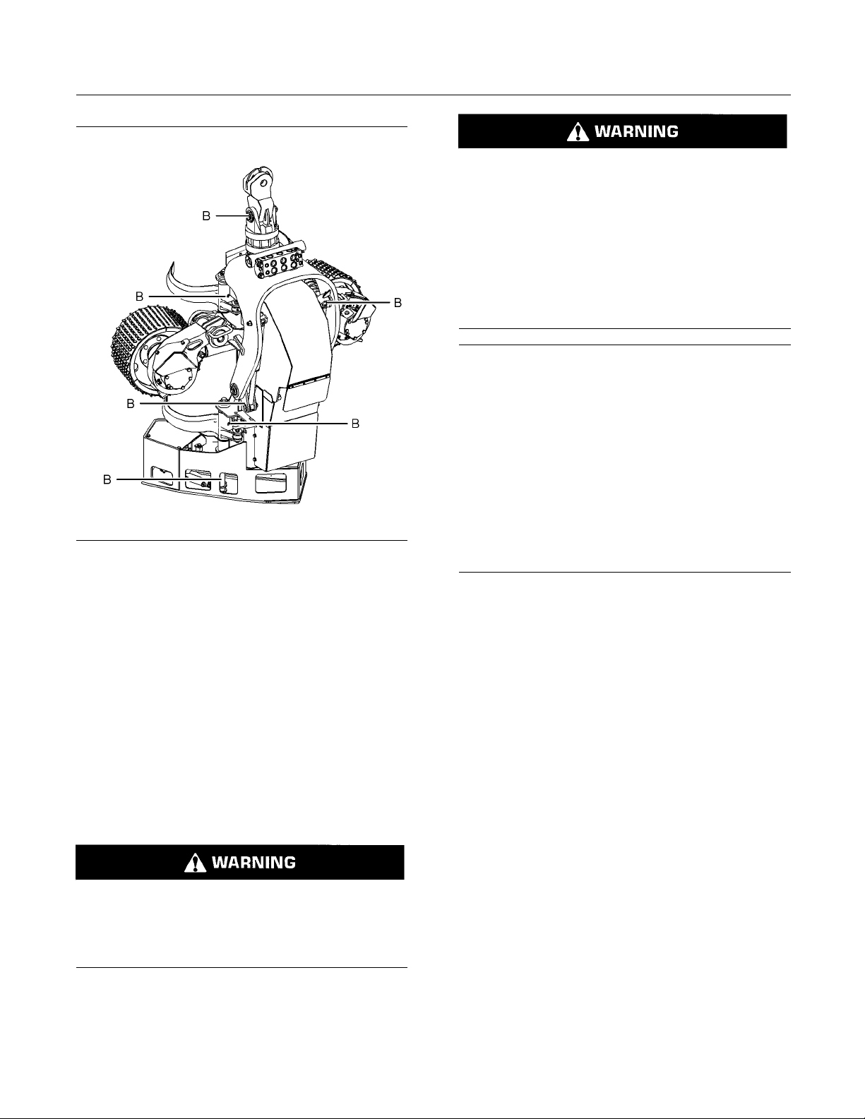
36 SEBU9062
Maintenance Section
Hydraulic Fittings - Inspect
Personal injury or death can result from improperly checking for a leak.
Always use a board or cardboard when checking
for a leak. Escaping air or fluid under pressure,
even a pin-hole size leak, can penetrate body tissue causing serious injury, and possible death.
If fluid is injected into your skin, it must be treated
immediately by a doctor familiar with this type of
injury.
NOTICE
Care must be taken to ensure that fluids are contained
during performance of inspection, maintenance, testing, adjus
to collect the fluid with suitable containers before
opening any compartment or disassembling any component co
ting, and repair of the product. Be prepared
ntaining fluids.
Illustration 39
example of grease zerk locations. Some locations may not
Typical
le. Grease all grease zerks daily.
be visib
3. Lubricate all retaining pins (B) grease zerks with
grease
of the Harvester Head.
Refer
Manual, SEBU6250, “Caterpillar Machine Lubricant
Recommendations” for information on proper
lubri
Hydr
SMCS Code: 5057-040-X6
Always perform service on the Harvester Head
m the side or the rear of the work tool.
fro
. Grease zerks are located on both sides
ence: Refer to Operation and Maintenance
cants.
aulic Fittin gs - Inspect
g02977256
i04471453
Refer to Special Publication, NENG2500, “Dealer Service Too
collect and contain fluids on Cat products.
Dispose
mandates.
1. Perform the following required steps before
l Catalog” for tools and supplies suitable to
of all fluids according to local regulations and
ming any maintenance procedure:
perfor
Secure the Harvester Head in the upright
•
•
•
•
•
•
ion with a chain
posit
Lower the Harvester Head to the ground
If equipped, engage the parking brake on the
host machine
Stop the engine on the host machine. Remove
the engine start switch key before exiting the
ine
mach
Turn the battery disconnect switch to the OFF
ition
pos
Relieve the hydraulic pressure on all functions
oving the joystick and control levers to
by m
relieve pressure
Could cause serious injury or death from improp-
ly servicing the Harvester Head.
er
rge all air from the reservoir
Pu
•
Refer to the Operation and Maintenance Manual
the host machine for additional information.
of
2. Clean and inspect areas around all hydraulic
ttings and all hydraulic hoses to insure there are
fi
no leaks.
Page 37
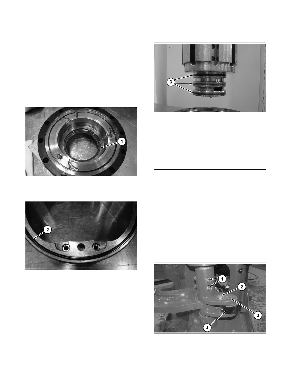
SEBU9062 37
Maintenance Section
Hydraulic Rotator Motor Seals - Replace
3. Replace any hyd
raulic fitting or hydraulic hose that
is found to be leaking.
i04664024
Hydraulic Rotator Moto r Seals
- Replace
SMCS Code: 6326-SA
Replace all seals in motor.
Illustration 40
Replace lip seal (1).
g02796412
Illustration 42
g02796424
Replace o-rings (3).
i04663936
Knife Pivot Pin - Replace
SMCS Cod
Care must be taken to ensure that fluids are contained
during performance of inspection, maintenance, testing, adjusting and repair of the product. Be prepared
to collect the fluid with suitable containers before operating any compartment or disassembling any component containing fluids.
e: 5554-KNF; 6321-KNF
NOTICE
Illustration 41
place o-ring (2)
Re
g02796415
After collecting all fluids in suitable containers, dispose
of all fluids according to local regulations and mandates.
1. In order to remove lower delimbing knife. Begin
with delimbing knives in the closed position and
with the harvester head in the HORIZONTAL
position.
Illustration 43
g02435636
2. Remove bolts (1) and (2). Remove pin (3) and
repostion cylinder (4).
Page 38
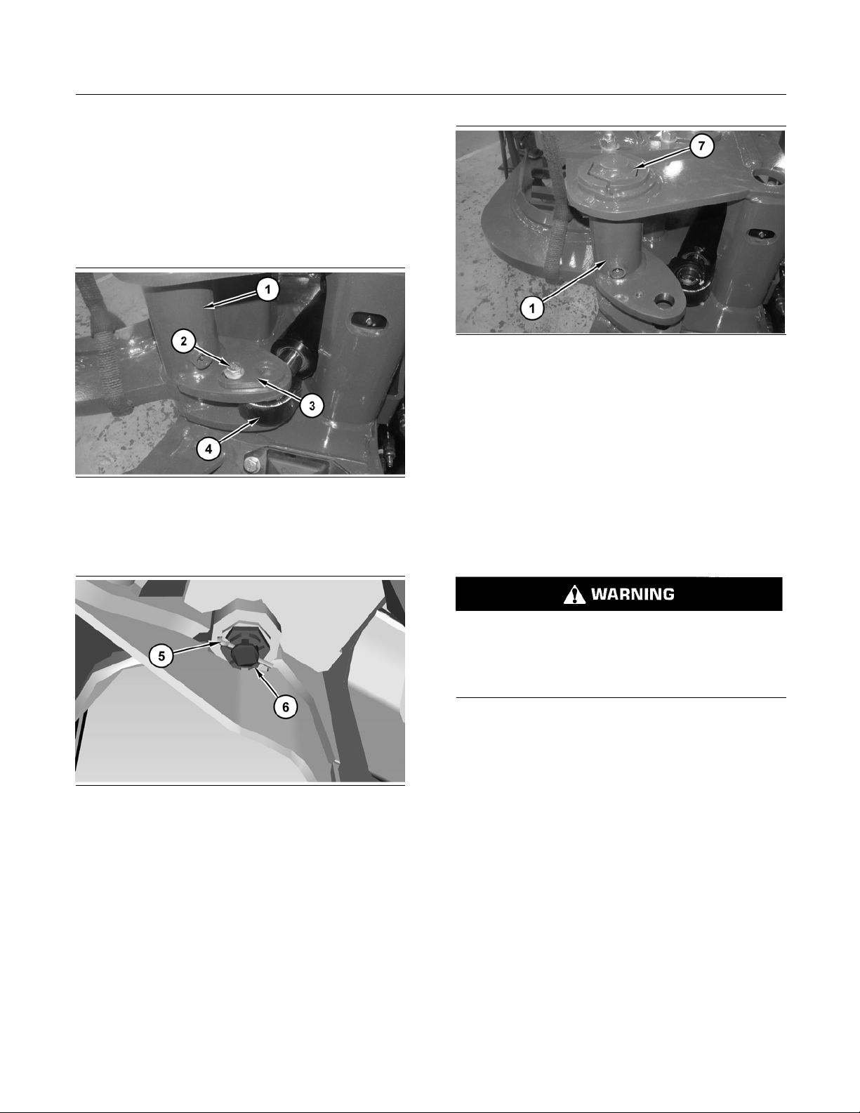
38 SEBU9062
Maintenance Section
Saw Bar - Inspect
Note: Lubricat
e pins before replacement.
3. Replace lower delimbing arm pins with new.
4. Install new lower delimbing knife pins in reverse
order of removal.
1. In order to remove upper delimbing knife,
reposition feed roller arms.
Illustr
ation 44
g02431076
2. Attach a suitable lifting device to upper delimbing
knife (1
). Remove bolt (2) and pin assembly (3).
Repostion cylinder (4).
Illustration 46
g02431077
4. Remove pin assembly (7).
5. Replace upper delimbing arm pins with new.
6. Install new upper delimbing knife pins in reverse
order of removal.
i04477834
Saw Ba r - Inspect
SMCS Code: 6327-040-BAR
Illustration 45
3. Remove cotter pin (5) and nut (6).
g02431237
Always perform service on the Harvester Head
from the side or the rear of the work tool.
Could cause serious injury or death from improperly servicing the Harvester Head.
1. Perform the following required steps before
performing any maintenance procedure:
Secure the Harvester Head in the upright
•
position with a chain
Lower the Harvester Head to the ground
•
If equipped, engage the parking brake on the
•
host machine
Stop the engine on the host machine. Remove
•
the engine start switch key before exiting the
machine
Turn the battery disconnect switch to the OFF
•
position
Relieve the hydraulic pressure on all functions
•
by moving the joystick and control levers to
relieve pressure
Page 39
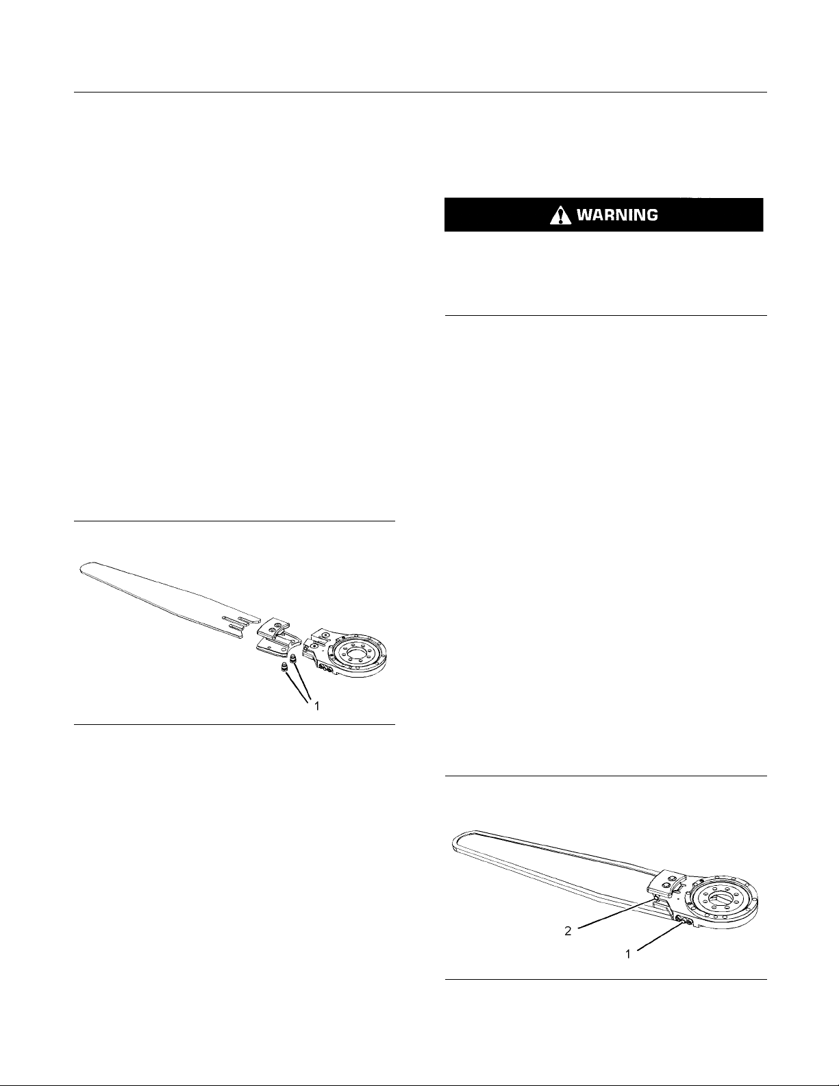
SEBU9062 39
Maintenance Section
Saw Chain - Remove/Install
Purge all air fr
•
Refer to the Operation and Maintenance Manual
of the host mac
om the reservoir
hine for additional information.
Inspect
1. Inspect the saw bar for damage such as bends,
wear, and cra
2. If the saw bar is bent or worn, repair the saw bar.
3. If the saw bar is cracked or damaged beyond
repair, replace the saw bar.
cks.
Repair
1. Refer to the manual for your specific saw bar for
the proper repair procedures.
Replace
1. Remove the saw chain. Refer to Operation
and Maintenance Manual, “Saw Chain
Remove/
Install”.
i04472534
Saw Chain - Remove/Install
SMCS Code: 6327-011-CX; 6327-012-CX
Always perform service on the Harvester Head
from the side or the rear of the work tool.
Could cause serious injury or death from improperly servicing the Harvester Head.
1. Perform the following required steps before
performing any maintenance procedure:
Secure the Harvester Head in the upright
•
position with a chain
Lower the Harvester Head to the ground
•
If equipped, engage the parking brake on the
•
host machine
Stop the engine on the host machine. Remove
•
the engine start switch key before exiting the
machine
Illustration 47
2. Loosen the guide screws (1).
3. Remove the saw bar.
4. Install the new saw bar.
5. Tighten the guide screws (1).
6. Install the saw chain. Refer to Operation
and Maintenance Manual, “Saw Chain
Remove/Install”.
g02694744
Turn the battery disconnect switch to the OFF
•
position
Relieve the hydraulic pressure on all functions
•
by moving the joystick and control levers to
relieve pressure
Purge a ll air from the reservoir
•
Refer to the Operation and Maintenance Manual
of the host machine for additional information.
Remove Chain
Illustration 48
02696436
g
Page 40
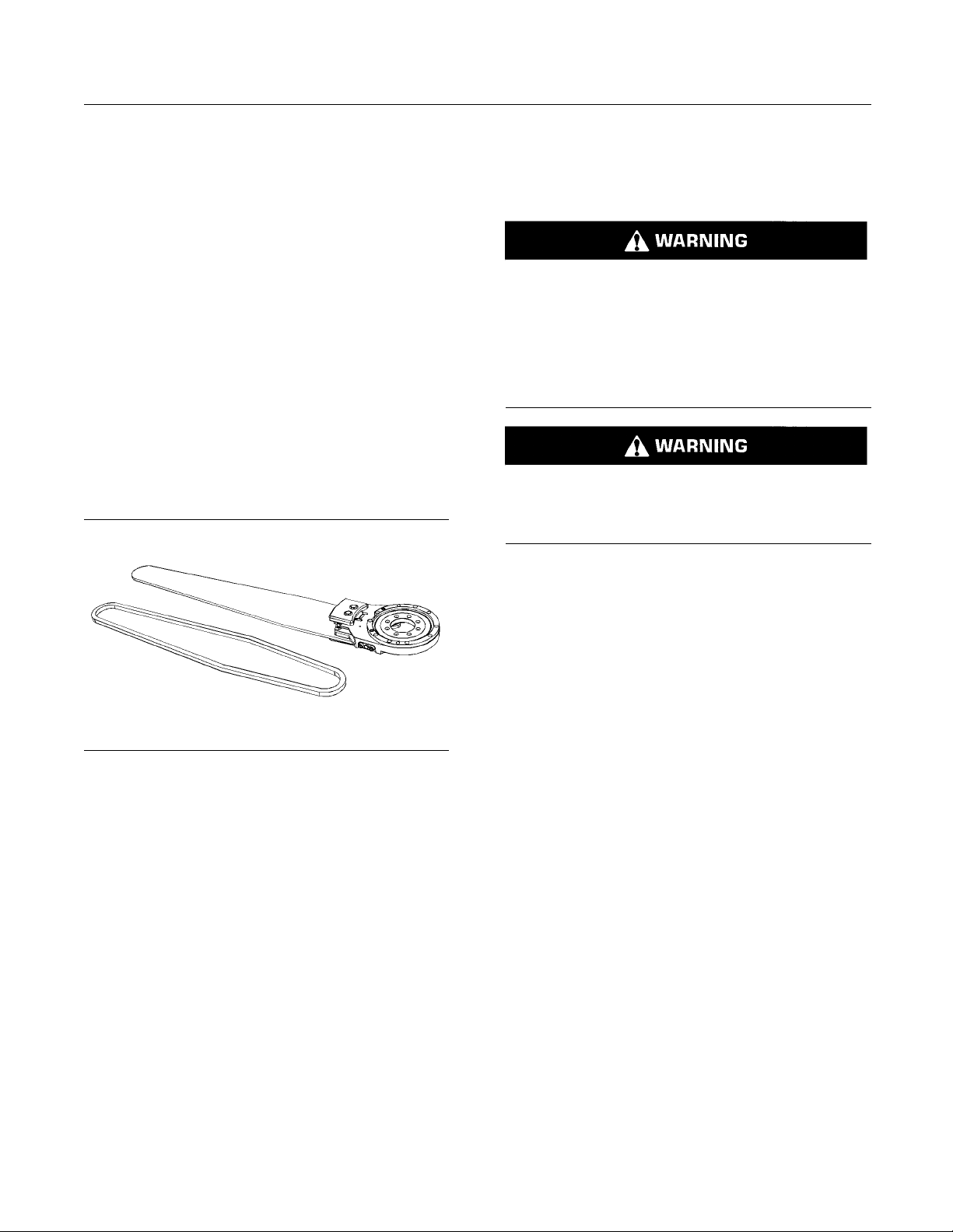
40 SEBU9062
Maintenance Section
Saw Chain - Sharpen
1. Use only hand fo
protection.
2. Press the pilo
the saw chain tensioning device.
3. Compress the
a. Whenthesawchainisonthesawbar,usethe
following p
Slowly pull the saw chain from the saw bar
•
until the te
b. When there in no saw chain on the saw bar,
use the fol
Slowly push the saw bar until the tensioning
•
device is c
4. Press the mechanical locking device (2) INWARD
to lock th
e tensioning device
rce and wear appropriate hand
t valve (1) INWARD to depressurize
tensioning device.
rocedure:
nsioning device is compressed.
lowing procedure:
ompressed.
i04477629
Saw Chain - Sharpen
SMCS Code: 6327-502-HHD
Never use dull or worn saw chains. Never use
worn or damaged saw bars.
Personal injury or death can result.
Always fol
tions and requirements regarding the proper use
and maintenance of saw chains and saw bars.
Operation of the harvester head can cause flying
debris. The flying debris can cause serious injury
or death. Stay clear of the harvester head while the
harvester head is in operation.
1. Perform the following required steps before
performing any maintenance procedure:
low the manufacturers recommenda-
Illustration 49
5. Remove the saw chain from the saw bar.
g02696463
Install Chain
1. Use only hand force and wear appropriate hand
protection.
2. Install the saw chain onto the saw bar. The cutting
edge on the saw chain must be on the top side
of the saw bar.
Note: If a new saw chain is installed, refer to the
manual for your specific saw chain for proper chain
break-in procedures.
3. Slowly pull the saw chain OUTWARD until the
mechanical locking device (2) disengages.
Secure the Harvester Head in the upright
•
position with a chain
Lower the Harvester Head to the ground
•
If equipped, engage the parking brake on the
•
host machine
Stop the engine on the host machine. Remove
•
the engine start switch key before exiting the
machine
Turn the battery disconnect switch to the OFF
•
position
Relieve the hydraulic pressure on all functions
•
by moving the joystick and control levers to
relieve pressure
Purge a ll air from the reservoir
•
Refer to the Operation and Maintenance Manual
of the host machine for additional information.
2. Remove the saw chain from the saw bar. Refer to
Operation and Maintenance Manual, “Saw Chain
- Remove/Install”.
3. Refer to the manual for your specific saw chain for
proper chain sharpening procedures.
Page 41
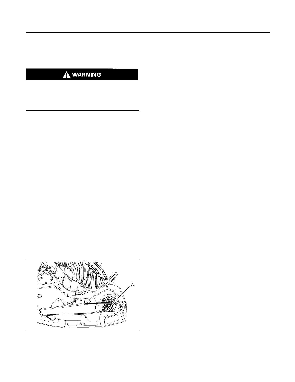
SEBU9062 41
Maintenance Section
Sprocket - Inspect
i04479609
Sprocket - In spect
SMCS Code: 4164-040
Always perform service on the Harvester Head
from the side or the rear of the work tool.
Could cause serious injury or death from improperly servicing the Harvester Head.
1. Perform the following required steps before
performing any maintenance procedure:
Secure the Harvester Head in the upright
•
position with a chain
Lower the Harvester Head to the ground
•
If equip
•
host machine
Stop the
•
the engine start switch key before exiting the
machine
Turn the battery disconnect switch to the OFF
•
position
Relieve the hydraulic pressure on all functions
•
by moving the joystick and control levers to
relie
Purge all air from the reservoir
•
Refer to the Operation and Maintenance Manual
of the host machine for additional information.
ped, engage the parking brake on the
engine on the host machine. Remove
ve pressure
Illustration 50
2. Inspect sprocket (A) for wear or damage.
3. Repair or replace the sprocket as needed.
g02659918
Page 42

42 SEBU9062
Reference Information Section
Reference Materials
Reference Information
Section
Reference Materials
i04841470
Reference Material
SMCS Code: 6320
Reference Material
Service Manual, 30014726, “PE44 Harvester
•
Head”
Special Publication, NENG2500, “Tools and Shop
•
Products Guide”
Special Publication, SEBU6250, “Machine Fluids
•
Recommendations”
Specifications, RENR3130, “Torque Specifications”
•
i04760825
Decommissioning and
Disposal
SMCS Code: 6320
When the product is removed from service, local
regulations for the product decommissioning will
vary. Disposal of the product will vary with local
regulations. Consult the nearest Prentice dealer for
additional information.
Page 43

SEBU9062 43
Index Section
Index
B
Bail Cylinde
Before Operation ................................................... 15
Burn Prevention...................................................... 11
Oils...................................................................... 11
C
Crushing Prevention and Cutting Prevention ......... 11
D
Daily Inspection ..................................................... 20
Decommissioning and Disposal ............................ 42
Delimbin
Delimbing Knife Cutting Edges - Sharpen............. 25
Delimbing Knife Cylinder Bearing - Replace ......... 27
Delimbi
E
Electrical Storm Injury Prevention ......................... 15
r and Mounting Bearings - Replace.... 24
g Knife Cutting Edges - Inspect............... 25
ng Knife Cylinder Seal - Replace............... 27
G
General Haza
Containing Fluid Spillage ................................... 10
Dispose of Waste Properly ................................. 11
Fluid Penet
Inhalation ........................................................... 10
Pressurized Air and Water ................................... 9
Trapped Pre
General Information............................................... 17
H
Harvester
Harvester Head (Bolts) - Inspect ..................... 33–34
Hydraulic Fittings - Inspect .................................... 36
Hydrauli
I
Identification Information ....................................... 19
Importa
K
rd Information .................................... 8
ration................................................ 10
ssure ................................................ 9
Head - Lubricate ................................... 35
c Rotator Motor Seals - Replace .............. 37
nt Safety Information ................................... 2
F
Feed Roller - Inspect (Motor)................................. 28
Feed Roller Arm Cylinder Bearing - Replace ........ 28
Feed R
Feed Roller Arm Pivot Pin - Replace..................... 30
Feed Roller Arm Stop - Replace............................ 31
Feed R
Feed Roller Motor Seal - Replace ......................... 32
Fire Prevention and Explosion Prevention ............ 12
For
oller Arm Cylinder Seal - Replace.............. 29
oller Cutting Edges - Inspect...................... 31
ery and Battery Cables ................................ 13
Batt
Ether .................................................................. 14
Fire Extinguisher ................................................ 14
ral .............................................................. 12
Gene
Lines, Tubes, and Hoses ................................... 14
Wiring................................................................. 13
eword ................................................................. 4
Literature Information........................................... 4
Maintenance ........................................................ 4
ration ............................................................. 4
Ope
Safety................................................................... 4
Knife Pivot Pin - Replace....................................... 37
M
Maintenance Interval Schedule ............................. 23
Maintenance Section ............................................. 22
enance Support ............................................ 22
Maint
O
Operation......................................................... 15, 20
ating the Harvester Head ........................... 20
Oper
Operation Section.................................................. 20
P
king .................................................................. 16
Par
Plate Locations and Film Locations....................... 19
Serial Number .................................................... 19
oduct Information Section .................................. 17
Pr
R
Reference Information Section .............................. 42
eference Material ................................................ 42
R
Reference Material............................................. 42
Page 44

44 SEBU9062
Index Section
Reference Mate
S
Safety Messages ..................................................... 5
Safety Secti
Saw Bar - Inspect .................................................. 38
Inspect ............................................................... 39
Repair ................................................................ 39
Replace.............................................................. 39
Saw Chain - Remove/Install .................................. 39
Install Cha
Remove Chain ................................................... 39
Saw Chain - Sharpen ............................................ 40
Specificat
Intended Use...................................................... 18
Sprocket - Inspect.................................................. 41
T
Table of Contents..................................................... 3
W
rials .............................................. 42
on ......................................................... 5
in ....................................................... 40
ions ........................................................ 17
Welding
Controls ............................................................... 22
Work Tools............................................................. 16
on Machines and Engines with Electronic
Page 45

Product and Dealer Infor mation
Note: For product identification plate locations, see the section “Product Identification Information” in the Operation
and Maintenance Manual.
Delivery Date:
Product Information
Model:
Product Identification Number:
Engine Serial Number:
Transmission Serial Number:
Generator Serial Number:
Attachment Serial Numbers:
Attachment Information:
Customer Equipment Number:
Dealer Equipment Number:
Dealer Inform atio n
Name: Branch:
Address:
Dealer Contact Phone Number Hours
Sales:
Parts:
Service:
Page 46

 Loading...