

Page 1
®
®
®
®
®
GAS
CONVEYOR OVEN
MODEL
UM1854-NAT/-LP
UM1854Q-NAT/-LP
UM1854-NATX/-LPX
Installation and
Operation
Instructions
2M-Z5649 Rev. L 10/20/2010
UM1854
Page 2

2
These symbols are intended to alert the user to the presence of
important operating and maintenance instructions in the manual
accompanying the appliance.
RETAIN THIS MANUAL FOR FUTURE REFERENCE
NOTICE
Using any part other than genuine Star factory supplied parts relieves the
manufacturer of all liability.
Star reserves the right to change specications and product design without
notice. Such revisions do not entitle the buyer to corresponding changes,
improvements, additions or replacements for previously purchased
equipment.
Due to periodic changes in designs, methods, procedures, policies and
regulations, the specications contained in this sheet are subject to change
without notice. While Star International Holdings Inc., Company exercises
good faith efforts to provide information that is accurate, we are not
responsible for errors or omissions in information provided or conclusions
reached as a result of using the specications. By using the information
provided, the user assumes all risks in connection with such use.
MAINTENANCE AND REPAIRS
Contact your local authorized service agent for service or required maintenance.
Please record the model number, serial number, voltage and purchase date in the area below and have it ready when
you call to ensure a faster service.
SAFETY SYMBOL
Model No.
Serial No.
Voltage
Purchase Date
Business
8:00 am to 4:30 p.m. Central Standard Time
Hours:
Telephone: (800) 264-7827 Local (314) 781-2777
Fax: (800) 396-2677 Local (314) 781-2714
E-mail Parts@star-mfg.com
Service@star-mfg.com
Warranty@star-mfg.com
Website: www.star-mfg.com
Service Help Desk
Authorized Service Agent Listing
Reference the listing provided with the unit
or
for an updated listing go to:
Website: www.star-mfg.com
E-mail Service@star-mfg.com
Telephone: (800) 807-9054 Local (314) 781-2777
Mailing Address: Star International Holdings Inc., Company
10 Sunnen Drive
St. Louis, MO 63143
U.S.A
3
Page 3
SPECIFICATIONS
UM1854-NAT, UM1854-LP
Gas Rating/Connection: 40,000 BTU/hr (10080 kCal/min)(703kW)
1/2" NPT male pipe connection
Gas Supply Pressure: Natural - 5-6" water column (15-30 mBar)
Propane - 11-12" water column (27.5-30 mBar)
Electrical Supply: Separate 15 Amp 110VAC, single phase, 50/60 Hz service per Oven
Approximate Weight (Single Oven with Cart): Installed - 280 Lbs (127.27 kg), Shipping - 350 Lbs (159.09 kg)
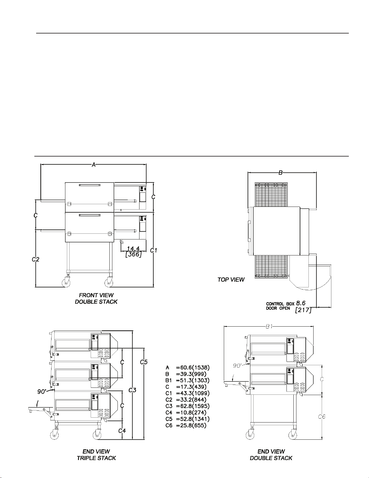
Dimensions: Width: 60.6" (153.9 cm)
Depth: 39.9" (99.82 cm) - Front Door(s) Closed
51.3" (130.3 cm) - Front Door(s) Open
Height: 43.3" (110.0 cm) - Single Oven with Stand
60.6" (153.9 cm) - Double Oven with Stand
62.8" (159.5 cm) - Triple Oven with Dolly
Recommended Minimum Clearances:
Rear of Oven to Wall 0" (0 cm)
Conveyor Extensions to Wall 6" (15.2 cm)
3
Page 4

CAUTION
GENERAL INFORMATION
This equipment is designed and sold for commercial use only by personnel trained and experienced in
its operation and is not sold for consumer use in and around the home nor for use directly by the general
public in food service locations.
First and foremost, each crate should be examined before signing the Bill of Lading to report any visible
damage by the trucker in transit and to account for the proper number of crates. If there is apparent
damage, arrangements should be made to le a claim against the carrier. Interstate Commerce
Regulations require that the claim must be initiated by the consignee. Proper and secure storage
facilities should be arranged for the oven(s) if necessary to protect it from outdoor or damp conditions
at all times before installation.
-IMPORTANT-
When you have all the crates unloaded, open the crates and remove all plastic covers. Inspect at once
for concealed damage. If anything appears to be damaged, contact the appropriate persons immediately
to le a damage claim. After completing this inspection, nish unpacking the oven. Be sure to remove
all paper protection and packing material from the unit prior to lighting.
FOR YOUR SAFETY DO NOT STORE OR USE GASOLINE OR OTHER FLAMMABLE
VAPORS AND LIQUIDS IN THE VICINITY OF THIS OR ANY OTHER APPLIANCE.
The installation of the Appliance must conform to the NATIONAL FUEL GAS CODE
"ANSI Z223.1 - LATEST EDITION" AND ALL LOCAL GAS COMPANY RULES AND
REGULATIONS.
IN CANADA INSTALLATION SHALL BE IN ACCORDANCE WITH THE CURRENT CAN/
CGA-B149.1 NATURAL GAS INSTALLATION CODE OR CAN/CGA-B149.2 PROPANE
INSTALLATION CODE AND LOCAL CODES WHERE APPLICABLE.
NOTICE
This appliance must be installed with a stand and casters designed by Star Manufacturing as part of a
complete installation. The installation must also include a connector complying with either ANSI Z21.69
or CAN/CGA-6.16 and a quick-disconnect device complying with either ANSI Z21.41 or CAN1-6.9. It
must also be installed with restraining means to guard against transmission of strain to the connector
as specied in the appliance manufacturer's instructions.
For your protection, we recommend a qualied installing agency install this appliance. They should be
familiar with gas installations and your local gas requirements. In any case, your gas company should
be called to approve the nal installation.
This appliance, its pressure regulator, and its individual shutoff valve must be disconnected from the
gas supply piping system during any pressure testing of that system at test pressures in excess of 1/2
PSIG. This appliance and its pressure regulator must be isolated from the gas supply piping system by
closing its individual manual shutoff valve during any pressure testing of the gas supply piping system
at test pressures equal to or less than 1/2 PSIG.
4
Page 5
CAUTION
PURCHASER'S RESPONSIBILITY
It is the responsibility of the purchaser:
1. To see that the gas and electric services for the oven are installed on site in accordance
with the manufacturer's specications.
2. To unload, uncrate, and install the oven in its proper location and in accordance with this
installation operation manual.
3. To see that all gas and electric services are connected properly by a qualied installer of your
choice. All such connections must be in accordance with applicable code requirements.
4. To arrange for inspection and operation check-out by an authorized service technician.
The warranty becomes effective upon verication of proper installation.
IMPORTANT SAFETY INFORMATION
Do not attempt to operate the oven until connection of utility service has been fully inspected by an
authorized service technician or a Star Service Representative. This service is required by Star in order
to assist the purchaser in proper start-up of the oven on site. Please note the specic details on the
Warranty and make certain that service connections are made to proper utility services.
The warranty shall not apply if the oven is started up and operated prior to the utilities and oven being
inspected and check-out made by an authorized service technician or a Star Service Representative.
IMPROPER INSTALLATION, ADJUSTMENT, ALTERATION, SERVICE, OR
MAINTENANCE CAN CAUSE PROPERTY DAMAGE, INJURY, OR DEATH. READ
ALL INSTRUCTIONS THOROUGHLY BEFORE INSTALLING OR SERVICING THIS
EQUIPMENT.
CAUTION
CAUTION
CAUTION
CAUTION
CAUTION
Post in a prominent location the emergency telephone number of your local gas
supplier and instructions to be followed in the event you smell gas. If the smell
of gas is detected, immediately call the emergency phone number of your local
gas company. They will have personnel and provisions available to correct the
problem.
It is required that the oven be placed under a ventilation hood to provide for
adequate air supply and ventilation.
Minimum clearances must be maintained from all walls and combustible materials.
Minimum clearances for this unit should be 0 inches from the rear (rear bumpers
provided must be in place) and 6 inches from both sides. Keep the oven free
and clear of all combustible material.
Adequate clearance for air openings to the combustion control chamber on the
right side of the oven is required. Do not obstruct the ventilation holes in the
control panels as these provide the combustion air for the burner and cooling
air for the controls.
The oven is to be operated only on the type of gas and electricity shown on the
specication plate. The burner will not operate and gas will not ow through the
burner without electric power.
5
Page 6

INSTALLATION INFORMATION
THE INSTALLATION INSTRUCTIONS CONTAINED HEREIN ARE FOR THE USE OF
QUALIFIED INSTALLATION AND SERVICE PERSONNEL ONLY. INSTALLATION OR
SERVICE BY OTHER THAN QUALIFIED PERSONNEL MAY RESULT IN DAMAGE
TO THE OVEN AND/OR INJURY TO THE OPERATOR.
Qualied installation personnel are individuals, a rm, a corporation, or a company which either in person
or through a representative are engaged in and responsible for:
1. The installation or replacement of gas piping and the connection, installation, repair, or servicing of
equipment.
2. The installation of electrical wiring from the electric meter, main control box, or service outlet to the
electric appliance.
Qualied installation personnel must be experienced in such work, familiar with all precautions required,
and have complied with all requirements of state or local authorities having jurisdiction.
LOCATION
The well-planned and proper placement of your oven will result in long-term operator convenience and satisfactory
performance.
NOTE: On gas conveyor ovens, routine servicing can usually be accomplished within the limited movement provided
by the gas hose restraint. If the oven needs to be moved further from the wall, the gas must rst be turned off and
disconnected from the oven before removing the restraint. Reconnect the restraint after the oven has been
returned to its regular position.
It is essential that an adequate air supply to the oven be maintained to provide a sufcient ow of
combustion and ventilation air. Follow these guidelines:
1. Place the oven in an area that is free of drafts.
2. Keep the oven area free and clear of all combustibles such as paper, cardboard, ammable liquids,
and solvents.
3. Do not place the oven on a curb base or seal to a wall. This will restrict the ow of air and prevent
proper ventilation to the blower motors. This condition must be corrected to prevent permanent
damage to the oven.
4. On all models, tripping of the blower motor's thermal overload device indicates an excessive ambient
temperature at the back of the oven. This condition must be corrected to avoid permanent damage
to the oven.
CAUTION
Failure to properly vent the oven can be hazardous to the health of the operator
and may result in operational problems, unsatisfactory baking, and possible
damage to the equipment.
Damage sustained as a direct result of improper ventilation will not be covered by the warranty.
6
Page 7
CAUTION
VENTILATION
A VENT IS REQUIRED: Local codes prevail. These are the "authority having
jurisdiction" as stated by the National Fire Protection Association, Inc. in NFPA
96-Latest Edition. For further ventilation information see below.
A ventilation hood is required to remove heat and cooking odors. For gas ovens, a ventilation hood is
also required to remove the products of combustion. The hood and HVAC installation must meet local
codes to gain approval by the authority having jurisdiction. Requirements may vary throughout the
country depending on the location by city, county, and state. Obtain information from the authority having
jurisdiction to determine the requirements for your installation. Obtain information and review copies
of codes or documents that will be used to inspect and approve your installation. Your ventilation hood
supplier and HVAC contractor should be contacted to provide guidance. A properly engineered and
installed ventilation hood and HVAC system will expedite approval and reduce oven maintenance costs.
Proper ventilation is the responsibility of the oven's owner.
The ventilation hood must operate in harmony with the building HVAC system. It typically requires between
750 and 2500 CFM exhaust. (The efciency of various hood designs makes it necessary to specify such
a wide range of ventilator CFM.) Make-up air must be supplied by either a hood design or the HVAC
system to avoid a negative pressure condition. This will vary with hoods from various manufacturers.
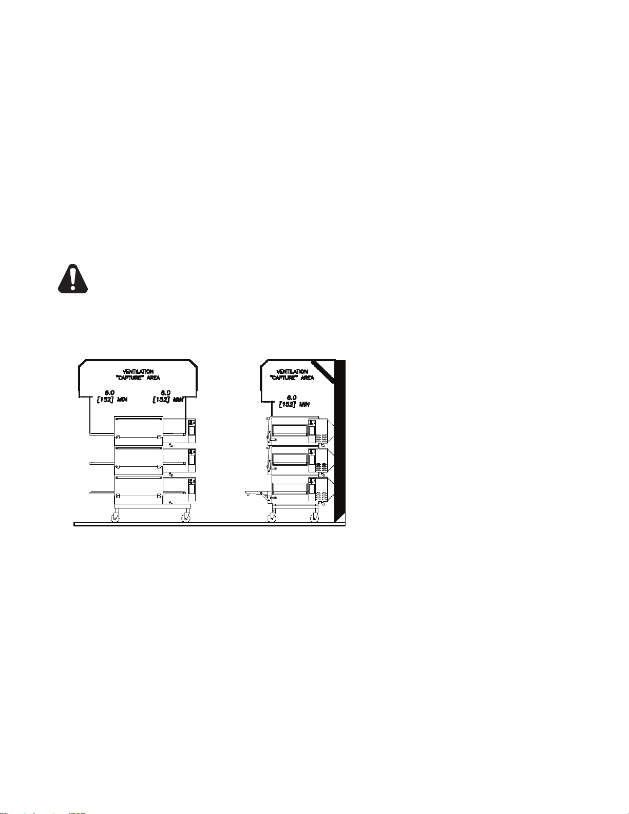
Prevent airow through the cooking tunnel. Air must NOT be directed onto the
oven's front or rear or to the sides of the cooking area.
The following drawing shows a typical installation
and is intended to be a guideline. This is not a rigid
specication. Hood dimensions and positioning
over the oven will vary with hood manufacturer.
SMOKE CANDLE TEST
In order to verify the proper function of your
ventilation system, a smoke candle test should
be done. If testing a multiple oven system, this
test should be done on the bottom oven. The
conveyor coupling should be disconnected and
the oven temperature must be set and operating
at a minimum of 480°F (249°C).
Test Procedure:
1. Wear heat-resistant gloves to prevent burns.
2. Put the smoke candle in an 8"x8"x2" cake pan.
3. Insert candle through conveyor tunnel or oven door.
(Use Star Smoke Candle 2W-Z5668.)
4. Light the fuse of the smoke candle and immediately center the pan in the oven cavity on the
conveyor belt (keeping the oven door closed).
5. Observe the smoke pattern coming out of all oven openings and the collection of this smoke by the
ventilation system.
6. All smoke from the oven must be captured by the ventilation system.
7
Page 8

GAS SUPPLY RATING AND SIZING
Calculations for pipe sizing must take into account the maximum usage rate of all other appliances in
the kitchen or one or more of the appliances will suffer from inadequate or dangerous performance. The
1/2" NPT connection for the oven is generously sized for use in the control box of the oven. However,
unless the oven installation is within 10 feet of the main building gas supply, the supply must be larger.
For each oven, a 3/4" NPT exible quick connect hose and full port gas shut-off valve is recommended
as a MINIMUM. The main pipe supplying each oven branch may need to be larger depending on the
number of appliances serviced, the number of elbows in the piping, and the pressure. This should be
sized and installed by a professional familiar with any local codes that may also affect the installation.
ACCESS CONSIDERATIONS
Locating the gas valve(s), quick connect hose(s) and electrical outlet(s) at the control box end of the
oven will allow easier access for any service visits. This improved access should make any necessary
service quicker resulting in less kitchen disruption. It will also allow easier disconnection of electricity,
gas, and restraints for cleaning around and behind the oven.
ELECTRICAL CONNECTION
Before making any electrical connections to this unit, check that the power supply is adequate for the
voltage, amperage, and phase requirements stated on the rating plate. A wiring diagram is included
herewith.
When installed, this appliance must be electrically grounded and its installation must comply with the
National Electric Code, ANSI-NFPA 70, latest version, manufacturer's installation instructions, and
applicable local municipal building codes. In Canada, all electrical connections are to be in accordance
with CSA C22.1 - Canadian Electrical Code Part 1 and/or local codes.
CAUTION
PRESSURE REGULATION AND TESTING
Each oven has been adjusted at the factory to operate with natural gas. Parts can be ordered for
conversion for use with propane.
Each oven is supplied with a regulator to maintain the proper gas pressure. The regulator is essential
to the proper operation of the oven and should not be removed. A pressure reading can be taken at one
of the 1/8" NPT test ports on the bottom or side of the combination valve. The reading should be taken
while the oven is heating up. The regulator is located on the bottom of the gas combination valve, just
inside the control box. There is no need to install an additional regulator where the oven connects to
the gas supply unless the supply exceeds the maximum.
NOTE: The supplied regulator is evaluated for a maximum gas supply pressure of
14" water column (34.5 mBar). The recommended maximum gas supply pressure
is 12" water column (29.9 mBar).
Installation must conform with local codes or, in the absence of local codes, with the National Fuel Gas
Code, NFPA54/ANSI Z223.1 - Latest Edition, the Natural Gas Installation Code CAN/CGA-B149.1 or
the Propane Installation Code CAN/CGA-B149.2 as applicable.
During pressure testing note the following:
1. The oven and its individual manual shut-off valve must be disconnected from the gas supply piping
system during any pressure testing of that system at test pressures in excess of 1/2 psig (3.45 kPa).
Turn OFF main gas shut-off valve or main gas supply line.
2. The oven must be isolated from the gas supply piping system by closing its individual manual shutoff valve during any pressure testing of the gas supply piping system at test pressures equal to or
less than 1/2 psig (3.45 kPa).
3. If incoming pressure is over 14" water column, a separate regulator for the oven must be installed
before the gas supply to the oven. For LP it must regulate pressure to 11" water column (27.1 mBar)
maximum and 6" for NAT.
8
Page 9

WARNING: To prevent damage to the control valve regulator during the initial
turn-on of gas, it is very important to open the manual shut-off valve very slowly.
After the initial gas turn-on, the manual shut-off valve must remain open except
during pressure testing as outlined in the above steps or when necessary during
service maintenance.
STACKING
The following instructions should be followed when
stacking more than one unit.
INSTRUCTIONS
Single Oven (or Bottom) Cart Install:
1. Remove door, conveyor, and nger assemblies.
2. Unbolt unit from shipping crate (2 bolts).
3. Turn unit on front as shown.
4. Slide legs into stand shelf and thread legs into
bottom of oven.
5. Install casters into bottom of legs. Place casters
with brakes to the front.
6. Position shelf as desired and fasten to legs.
7. CAREFULLY lift oven upright.
Stacked Oven Install Preparation:
1. Remove door, conveyor, and nger assemblies.
2. Unbolt unit from shipping crate (4 bolts).
3. Turn unit on front as shown.
4. Remove top of lower oven (4 screws total, 2 each
front and rear) and bolt to stacked oven base using
5/8 - 11 bolts (4 each, included).
5. Place top oven on lower unit and re-attach with
screws for top of lower oven.
6. Use restraint on lowest oven to prevent any high
loads that could tip the oven stack.
9
Page 10

RESTRAINT REQUIREMENT
HOLLOW WALL STUD
OR MASONRY WALL
A
B
C
1. The installation shall be made with a gas connector that
complies with local codes for connectors for movable
gas appliances and a quick-disconnect device that
complies with local codes for such devices in use
with gas fuel.
2. The installation of the restraint must limit the movement
of the oven(s) without depending on the connector,
the quick disconnect device, or associated piping to
limit the oven movement.
3. If the restraint must be disconnected during
maintenance or cleaning, it must be reconnected after
the oven has been returned to its originally installed
position.
OPERATING INSTRUCTIONS
DO NOT ATTEMPT TO OPERATE THE OVEN until
connection of utility service and installation has been fully
inspected (start-up check-out) by an authorized service
technician or a Star Service Technician in order to assure
the oven is properly installed and in working order. The
warranty becomes effective upon verication of
proper installation.
CAUTION
DO NOT WORK AROUND THE CONVEYOR
BELT WITH LONG HAIR, LOOSE CLOTHING,
OR DANGLING JEWELRY. GETTING
CAUGHT IN THE BELT COULD RESULT IN
DISMEMBERMENT OR FATAL INJURY.
Unless specied otherwise, conveyor travel is factory
set for left to right operation when facing the front of the
oven. If a direction change is required, refer to "DISPLAY
INFORMATION," section 3 for instructions on how to
program the controller for a direction change. In addition,
the conveyor belt must be changed to travel in the new
direction.
SAFETY OPERATING INSTRUCTIONS
The information contained in this section is provided
for the use of qualied operating personnel. Qualied
operating personnel are those who have carefully read
the information contained in this manual, are familiar
with the functions of the oven and/or have had previous
experience with the operation of the equipment described.
Adherence to the procedures recommended herein will
assure the achievement of optimum performance and
long, trouble-free service.
10
Page 11

Please take time to read the following safety
3) Press the up button ( ) to increase
or the down button ( ) to decrease
TIME or TEMPERATURE. Hold
button down for faster display
changes.
4) After five seconds, the new numbers
will be saved and the oven will display
new settings.
4) Après cinq secondes, les nouveaux
nombres seront sauvés et le four montrera
de nouveaux arrangements.
3) Tenez "vers le haut" bouton ( ) pour
augmenter ou "vers le bas" boutonnez ( )
pour diminution de le TEMPS ou
TEMPÉRATURE. Maintenez le bouton pour
des changements plus rapides.
1) Press the up and down buttons
( ) at the same time, hold for four
seconds until TIME display is blank.
2) Press the enter button ( ) to
switch between TIME and
TEMPERATURE.
Adjusting TIME and TEMPERATURE:
If burner does not light in one minute
push the power switch to the "OFF"
position and wait five minutes.
After five minutes, retry.
Push power switch "ON."
To Start:
2) Appuyez sur le bouton de "entrée" ( )
pour commuter entre le TEMPS et la
TEMPÉRATURE.
1) Tenez "vers le haut" et "vers le bas"
boutonne ( ) en même temps. Tenez
les boutons pendant quatre secondes
jusqu'à ce que l'affichage de la
TEMPS soit blanc.
Après cinq minutes, nouvelle tentative.
Si le brûleur n'allume pas en une minute,
poussée le commutateur de puissance dans
la position de "ARRÊTE" et attend 5 minutes.
Poussez le commutateur de puissance à
"MARCHE."
OFF / ARRÊTE
Ajustement du TEMPS et de la
TEMPÉRATURE:
Pour Commencer:
ON / MARCHE
SWITCH CUTOUT
IL1050
operating instructions. They are the key to the
successful operation of your Ultra-Max Conveyor
Oven.
SAFETY TIPS
For your safety, read before operating.
If you smell gas:
1. DO
NOT try to light any appliance.
2. DO NOT touch any electrical switches.
3. Use an exterior phone to call your gas supplier
immediately.
4. If
you cannot reach your gas supplier, call the
re department.
In the event of a power failure:
1. Turn all switches off.
2. DO NOT attempt to operate the oven until the
power is restored.
NOTE: In the event of a shut-down of any
kind, allow a ve (5) minute shut-off period
before attempting to restart the oven.
General Safety Tips:
1. DO NOT use tools to turn off the gas control. If
2. If the oven needs to be moved for any reason,
3. DO NOT remove the control box cover unless
the gas cannot be turned off manually do not try
to repair it. Call a qualied service technician.
the gas must be turned off and disconnected
from the unit before moving the restraint cable.
Reconnect the restraint after the oven has been
returned to its original location.
the oven is unplugged.
To adjust the time and temperature:
1. Press the DOWN and UP arrows ( ) at
the same time. Hold for four seconds until the
TIME display goes blank.
2. Press the ENTER button (
) to switch between
TIME and TEMPERATURE.
3. Press the UP arrow (
DOWN arrow (
) to decrease the TIME or
) to increase or the
TEMPERATURE. Hold either button down for
faster display changes.
4. After ve seconds, the new numbers will be saved
and the oven will display the new settings.
To turn the oven off:
1. Push the power switch to "OFF." The oven is
equipped with a cool-down feature for motor
shaft and bearing protection. This enables the
blower motor(s) to run regardless of the controller
status. The blower(s) continue to run until the
oven cools to a safe temperature.
OPERATION
To turn the oven on:
1. Push the power switch to "ON."
2. If the burner does not light in one minute, push
the power switch to the "OFF" position and wait
ve minutes.
3. After ve minutes, retry.
11
Page 12

DISPLAY INFORMATION
When operating the oven, there are different
levels of access:
1. Store Level - General employees would know
these functions and how to change them. While
the oven is running, enter this mode by holding the
DOWN and UP arrows ( ) simultaneously for
four seconds. The TIME display goes blank and the
TEMP setpoint is displayed. Adjust with the DOWN
or UP arrows. The ENTER button (
between TIME and TEMP. The parameter that can
be adjusted is displayed, the other is blank. When
TIME and TEMP are adjusted as needed, wait ve
seconds and SAVE is displayed. The values are
accepted and the controller begins controlling to these
new values. The conveyor continues to operate at
the same speed until a new value is accepted. The
temperature control output should be OFF during
changes.
2. Manager Level - This is a lock so that TIME and
TEMP cannot be changed even at the Store Level.
While the oven is running, enter this mode by holding
the DOWN and UP arrows simultaneously for 4
seconds. The TIME display goes blank and the TEMP
setpoint is displayed. Release the UP arrow and
continue to hold the DOWN arrow for an additional
4 seconds. The TEMP display shows LOC as the
TIME display shows nO, which indicates that the
TIME/TEMP parameters can be changed. af ter
reaching the STORE level. yES indicates that the
parameters cannot be changed even after entering
the STORE level. The LOC setting can be toggled
using the ENTER button ( ).
) toggles
ADDITIONAL FUNCTIONS
The conveyor belt direction and the temperature display can
be changed on the conveyor oven by a qualied technician.
To change the belt direction, the technician must reverse the
motor direction and rotate the conveyor belt for proper oven
function. A technician can also change the temperature display
from Fahrenheit to Celsius. These changes can be made by
the technician during the start-up/check-out or at a later date.
ERROR CODES
Error codes will display as ashing text messages for diagnostic
purposes. Any temperature or thermocouple error should turn
the temperature output OFF and leave the conveyor running
at the same speed. The belt error should turn the temperature
output OFF. The speed error should display when the motor is
unable to settle at the chosen speed. This might occur if a fast
speed is chosen that the motor is unable to spin fast enough
to achieve. The speed signal output will remain the same but
the display will ash the error message.
12
Page 13

BAKE TIME VERSUS TEMPERATURE
BAKE vs. DELIVERY TIME
Time to Delivery changes with product
but
Bake Time remains constant
at a steady conveyor speed.
28 (BAKE)
36 (DELIVERY)
44 (DELIVERY)
6:00 (BAKE)
7:43 (DELIVERY)
9:26 (DELIVERY)
1. Bake time is actually conveyor speed and is dened
as the time the product is actually in the oven. This is
measured by noting the time when the leading edge of
the product enters the oven and the time the leading
edge of the product leaves the oven. This is adjusted
by using the conveyor speed controller.
2. Bake temperature is adjusted by changing the setpoint
of the temperature controller to the desired bake
temperature. When the oven reaches the desired
temperature, the red dot in the lower right corner of the
temperature display will turn off and on as the controller
maintains the temperature.
3. When establishing a bake time and temperature for a
given product, the general rule shall be as the bake
time increases the bake temperature decreases and the
reverse is also true; increase temperature, decrease time.
However, there are limits to the above rule. Going to
extremes will result in a burnt exterior and raw interior or it
will result in a very light color but over-baked product.
4. Once a good bake has been established, the ne
adjustments should be made by holding either the bake
time or bake temperature constant, then varying the
other.
CONVEYOR SPEED
Bake Time (Conveyor Speed) - As stated previously, bake
time (conveyor speed) is dened as the amount of time
elapsed between the time the leading edge of the product
enters the oven and the leading edge of the product exits
the oven. Bake time is controlled by adjusting the digital
speed controller. The setting on the control panel indicates
the actual bake time.
Bake time will be the same for any size product.
TIME OF DELIVERY
The time of delivery is the amount of elapsed time between
the period when the leading edge of the product enters the
oven and the trailing edge of the product is fully discharged
and is ready to be delivered to the customer.
Time of delivery changes if the product size changes.
Tip: Train yourself not to pull the product out of the oven
when the leading edge comes out. Always wait until the entire
product is out - the product needs this time to fully bake.
13
Page 14

WARNING
CAUTION
CAUTION
MAINTENANCE INSTRUCTIONS
DISCONNECT THE POWER SUPPLY BEFORE SERVICING OR CLEANING THIS
OVEN. SAFEGUARD THE POWER SO IT CANNOT BE ACCIDENTALLY RESTORED.
FAILURE TO DO SO COULD RESULT IN DISMEMBERMENT, ELECTROCUTION,
OR FATAL INJURY. THERE IS MORE THAN ONE POWER SUPPLY CONNECTION
POINT WHEN OVENS ARE STACKED, SO MAKE SURE THAT ALL SWITCHES ARE
IN THE OFF POSITION BEFORE CLEANING OR MAINTENANCE.
No electrical components should be subjected to moisture. It is therefore important that the oven is wiped
down carefully. NEVER throw buckets of water over the oven or subject it to pressure washing from a
hose or a pressure spray. If water or other liquid is spilled on the oven, make sure that none of it has
entered the control box area before switching the oven ON. If in doubt, call your service company.
Adhere to the following warnings when cleaning or maintaining your gas conveyor oven:
1. The oven must be cool. Do not use power cleaning equipment, steel wool, or wire brushes on
stainless steel surfaces.
2. Do not use a caustic or an alkaline base cleaner on the interior of the oven. This will ruin the
aluminized nish of the oven interior.
3. When using cleaning solutions, be sure they meet local and national health standards.
If the gas oven needs to be moved, the gas must be turned off and disconnected
from the unit before moving the restraint. Reconnect the restraint after the oven
has been returned to its original location.
Follow this recommended cleaning schedule for proper oven performance:
DAILY
1. Clean the conveyor belt using a nylon brush. Allow any foreign material to drop into the crumb
pans.
2. Empty and clean the crumb pans. Use a hot water and detergent mix.
Rinse with clean water.
EVERY MONTH
1. Brush and clean the guard on the motor cooling fan.
EVERY THREE MONTHS
1. Unplug the oven and disconnect gas connections.
2. Remove the crumb pans.
3. Remove the conveyor assembly.
4. Unlatch and remove the front door. Remove all internal airow components.
5. Clean the oven interior with an appropriate oven cleaner.
6. Clean the conveyor assembly, crumb pans, and other removable components. Wash in a hot water,
detergent mix and rinse with clean water. For difcult cleaning areas, use a heavy-duty de-greaser
or oven cleaner.
7. Move the oven and clean under it. Be careful not to damage the oven's gas hose or electrical cords
when moving.
8. Reassemble the oven.
EVERY TWELVE MONTHS
A factory authorized service person should:
1. Open and clean the inside of the control box.
2. Check and tighten all electrical components.
If maintenance is required, contact your local service company, a factory representative,
or Star Manufacturing.
14
Page 15

DIRECTIONS FOR DISASSEMBLY
1. Remove crumb trays and
shelves from both ends.
4. Finish removing the conveyor
assembly from the right end of
the oven.
2. Push the spring-loaded coupling
in to disengage the pin in the
shaft. Rotate the shaft so the pin
will not go back in the coupling
slots.
5. Upper nger assembly can be
removed complete or the small
handle (left) can be used to slide
nozzle and columnating plate
out before removing the main
body.
3. Lift up the left end of the conveyor
frame so the crumb tray supports
clear the tunnel opening. Push
the conveyor frame through the
tunnel opening.
6. Upper nozzle (with slot) and
columnating plates (with tab).
Extruded holes all point in the
same direction (down toward
the conveyor).
7. The lower nger assembly can
be removed complete or the
nozzle can be slid off to reveal
the recessed columnating
plate.
8. The columnating plate also has
a slot that must align with a tab
on the nger to ensure proper
orientation. Extruded holes
point up toward the bottom of
the conveyor.
15
9. The oven body is now ready to
be wiped clean. Reassemble
the nger and conveyor parts
in the reverse order after
cleaning.
Page 16

CONVEYOR BELT TENSION
The conveyor belt of the Ultra-Max Gas Conveyor Oven
does not have a tension adjustment. If the belt becomes
too loose, a link will have to be removed to tighten. A
belt that is too tight will also cause operational problems
due to excessive drag. We suggest that you have a
qualied service technician perform this adjustment.
CAUTION
Careful consideration should be exercised prior
to removing a belt link because a belt that is
too tight will impede the smooth operation of
the conveyor.
CONVEYOR BELT LINK REMOVAL
An entire link can be removed with the conveyor
assembly either in or out of the oven. This may be
necessary as the belt stretches after continuous
use. Following are the necessary steps for
removing links:
1. Move the splice clips to either end of the oven
for easy access.
2. Unhook the splice clips using long nose
pliers.
3. Unhook
out. Do not discard the link removed as it may
be used for making spare splice clips.
4. Reconnect the inside splice clips.
5. Reconnect the outside splice clips.
6. Replace all parts removed from the oven.
7. Straighten any bent wires to ensure smooth
sprocket engagement.
the full link to be removed and slide it
Remove the outside master links on the right and left
sides of the conveyor belt. Remove the center splice
clips next.
Unhook the end loop and pull up on the link section.
Save this link as it may be used for making splice
clips.
Check the
should be up). The belt shown is the top section,
ready for left-to-right travel.
orientation of the splice clips (the hooks
16
Page 17

2M-4497-2 10/2010
The foregoing warranty is in lieu of any and all other warranties expressed or implied and constitutes the entire warranty.
FOR ASSISTANCE
Should you need any assistance regarding the Operation or Maintenance of any Star equipment; write, phone, fax or email our Service Department.
In all correspondence mention the Model number and the Serial number of your unit, and the voltage or type of gas you are using.
ALL:
* Pop-Up Toasters
* Butter Dispensers
* Pretzel Merchandisers
(Model 16PD-A Only)
* Pastry Display Cabinets
* Nacho Chip Merchandisers
* Accessories of any kind
* Sneeze Guards
* Pizza Ovens
(Model PO12 Only)
* Heat Lamps
* Pumps-Manual
Visit our Website at: www.star-mfg.com Email: service@star-mfg.com
THOROUGHLY INSPECT YOUR UNIT ON ARRIVAL
This unit has been tested for proper operation before leaving our plant to insure delivery of your unit in perfect condition. However, there are instances in
which the unit may be damaged in transit. In the event you discover any type of damage to your product upon receipt, you must immediately contact the
transportation company who delivered the item to you and initiate your claim with same. If this procedure is not followed, it may affect the warranty status of
the unit.
LIMITED
EQUIPMENT WARRANTY
All workmanship and material in Star products have a one (1) year limited warranty on parts & labor in the United States and Canada. Such warranty is limited
to the original purchaser only and shall be effective from the date the equipment is placed in service. Star's obligation under this warranty is limited to the repair
of defects without charge, by the factory authorized service agency or one of its sub-agencies. Models that are considered portable (see below) should be taken
to the closest Star service agency, transportation prepaid.
> Star will not assume any responsibility for loss of revenue.
> On all shipments outside the United States and Canada, see International Warranty.
* The warranty period for the JetStar six (6) ounce & Super JetStar eight (8) ounce series popcorn machines is two (2) years.
* The warranty period for the Chrome-Max Griddles is ve (5) years on the griddle surface. See detailed warranty provided with unit.
* The warranty period for Teon/Dura-Tec coatings is one year under normal use and reasonable care. This warranty does not apply if damage occurs to
Teon/Dura-Tec coatings from improper cleaning, maintenance, use of metallic utensils, or abrasive cleaners, abrasive pads, product identiers and
point-of-sale attachments, or any other non-food object tha comes in continuous contact with the roller coating. This warranty does not apply to the
“non-stick” properties of such materials.
> This warranty does not apply to "Special Products" but to regular catalog items only. Star's warranty on "Special Products" is six (6) months on parts
and ninety (90) days on labor.
> This warranty does not apply to any item that is disassembled or tampered with for any purpose other than repair by a Star Authorized Service Center or
the Service Center's sub-agency.
> This warranty does not apply if damage occurs from improper installation, misuse, wrong voltage, wrong gas or operated contrary to the Installation and
Operating instructions.
> This warranty is not valid on Conveyor Ovens unless a "start-up/check-out" has been performed by a Factory Authorized Technician.
PARTS WARRANTY
Parts that are sold to repair out of warranty equipment are warranted for ninety (90) days. The part only is warranted. Labor to replace the part is chargeable to
the customer.
SERVICES
NOT COVERED BY WARRANTY
PORTABLE EQUIPMENT
Star will not honor service bills that include travel time and mileage charges for servicing any products considered "Portable" including items listed below.
These products should be taken to the Service Agency for repair:
1. Travel time and mileage rendered beyond the 50 mile radius limit
2. Mileage and travel time on portable equipment (see below)
3. Labor to replace such items that can be replaced easily during a daily cleaning
routine, ie; removable kettles on fryers, knobs, grease drawers on griddles, etc.
4. Installation of equipment
5. Damages due to improper installation
6. Damages from abuse or misuse
7. Operated contrary to the Operating and Installation Instructions
8. Cleaning of equipment
9. Seasoning of griddle plates
10. Voltage conversions
11. Gas conversions
12. Pilot light adjustment
13. Miscellaneous adjustments
14. Thermostat calibration and by-pass adjustment
15. Resetting of circuit breakers or safety controls or reset buttons
16. Replacement of bulbs
17. Replacement of fuses
18. Repair of damage created during transit, delivery, &
installation OR created by acts of God
* The Model 510FD Fryer.
* The Model 526TOA Toaster Oven.
* The Model J4R, 4 oz. Popcorn Machine.
* The Model 518CMA & 526CMA Cheese Melter.
* The Model 12MC & 15MC & 18MCP Hot Food Merchandisers.
* The Model 12NCPW & 15NCPW Nacho Chip/Popcorn Warmer.
* All Hot Dog Equipment except Roller Grills & Drawer Bun Warmers.
* All Nacho Cheese Warmers except Model 11WLA Series Nacho Cheese Warmer.
* All Condiment Dispensers except the Model HPD & SPD Series Dispenser.
* All Specialty Food Warmers except Model 130R, 11RW Series, and 11WSA Series.
* All QCS/RCS Series Toasters except Model QCS3 & RCS3 Series.
* All Fast Steamer Models except Direct Connect Series.
Page 18

DSIC
SENSE 4
M.V. 3
THS 2
GND
5
1 24VDC RETURN (COMMON)
7 +24VDC
2 DIRECTION
3 ENABLE (ACTIVE LOW)
4 FAULT (ACTIVE LOW)
5 DIRECTION INDICATOR
6 COMMON
8 TACH (12 PPR)
9 VOLTAGE INPUT (SPEED)
10 +5V (USE FOR SPEED POT ONLY)
11 BRAKE (ACTIVE LOW)
12 COMMON
XF1
GM/C
TL1
TS1
TL2
20
27
28
X
X
X
12
11
10
9
8
7
1
2
3
4
5
6
13
42
29
X
X
12
M1
6
4
2
1
3
5
1
BLK
CB
24V
COM 120V
7
19
17
40
16
N
G
L1
BLK
WHT
7
6
DS
2
S1
8
30
15
25
14
34 23
26
37
26
37
TB
4
_
8 9
5
36
10
_
21
41
21
19
_
_
_
30
WHT
--
15
9
32
35
24
SV
DV
GRN
3
FS
SE
33
38
25
40
17
38
24
16
35
PLUG ON BACK OF MOTOR
IS SHOWN ROTATED 180°
12
27
29
28
42
X
34
_
23
25
33
10
CN1 T/C TYPR K
YEL(+) RED(-)
SH (SHIELD)
CN3
TO MOTOR
6 = COM
5 = ENABLE
4 = DIR
3 = SPEED
2 = COM
1 = TACH
1
CN2 (24V)
INPUT
2 = N
1 = H
CN4
CN4
OUTPUT TO
SOLENOID
3 = COM
2 = 24V
1 = N/C
1
CN2
1
CN3
OCB
SECOND GENERATION
CN1
1
CN5 TO
SMALL MOTOR
7 = SPEED (GRD)
6 = SPEED SIGNAL
5 = SPEED (5V REF)
4 = (NOT USED)
3 = TACH (GND)
2 = TACH (+5V)
1 = TACH SIGNAL
D
Page 19

1,2: AC IN
3: FG
4,5: -V OUT
6,7: +V OUT
PS
GM/C
C1
DSIC
PS
M1
OCB
TS1
TL2
TL1
CB
SE
FS
DS
S1
XF1
SV
DV
TB
T/C
PR
- GEARMOTOR & CONTROLLER
- CAPACITOR, CIRC FAN MOTOR
- DIRECT SPARK IGNITION CONTROLLER
- POWER SUPPLY, 24VDC 150W PS
- MOTOR, CIRC FAN
- OVEN CONTROL BOARD
- COOL DOWN T-STAT
- CONTROL BOX TEMP LIMIT (MAN RESET)
- COOK CHAMBER TEMP LIMIT (BULB & CAP)
- CIRCUIT BREAKER
- SPARK ELECTRODE
- FLAME SENSOR
- DIFFERENTIAL PRESSURE SWITCH
- SWITCH, MAIN
- TRANSFORMER, 24V
- SINGLE VALVE
- DUAL VALVE (COMBI)
- TERMINAL BLOCKS (2)
- THERMOCOUPLE ASSY
- POWER RESISTOR
361320
41
12
3
4
5
6
7
8
BLK
BRN
BLU
M1
C1
TL1
TL2
TS1
CB
SE
FS
32
37
26
37
TB
5
36
10
41
21
19
30
WHT
--
35
24
DV
SET VOLTAGE SWITCH
TO 115V BEFORE INSTALLING
14
34
_
23
25
33
4
T/C
PR
10
14
"H"
C
NO
NC
"L"
DS
CN1 T/C TYPR K
YEL(+) RED(-)
SH (SHIELD)
INPUT
2 = N
1 = H
CN4
CN4
1
CN2
1
CN1
D
R
MATERIAL
DR.
FINISH
TITLE
STAR MFG. INTERNATIONAL, INC.
#10 SUNNEN DRIVE, ST. LOUIS, MO. 63143, USA
TOLERANCES UNLESS OTHERWISE NOTED
FRACTIONS ±1/64 DECIMALS ±.005 ANGLES ±1°
NO REPRODUCTION OR DISCLOSURE OF ITS CONTENTS IS PERMITTED.
CK.
-
-RDLEE 01-10-02
DATE
RDL
A 08/28/02
CHANGED POWER RESISTOR
AND IT'S WIRING
RDL
B 12/09/02
ADDED PICTURE OF
DIFFERENTIAL PRESSURE SWITCH
RDL
C 11/21/03
UPDATE FOR LOW
VOLTAGE CONTROLLER
CG
D 9/23/04
UPDATED OVEN CONTROL BOARD
MODEL NO. PART NO.
DESCRIPTION OF CHANGE
THIS DRAWING CONTAINS INFORMATION CONFIDENTIAL TO STAR MFG. INT'L INC.
DR
REVISIONS
UM-1854
SK1875
DIAGRAM, GAS OVEN - 115V
LTR DATE
Page 20

1678 2345
1
8
10
29
38
26
23
22
25
27
21
24
39
13
20
17
18
16
15
14
3
4
6
9
5
7
11
12
19
31
32
2
34
33
35
36
37
STAR MANUFACTURING INTERNATIONAL, INC.
MODEL UM1854
SK1905 REV.B 2-7-06
CONTROL BOX ASSEMBLY
SOME ITEMS ARE INCLUDED FOR ILLUSTRATIVE
PURPOSES ONLY AND IN CERTAIN
INSTANCES MAY NOT BE AVAILABLE.
THIS DRAWING CONTAINS INFORMATION CONFIDENTIAL
TO STAR MANUFACTURING INTERNATIONAL, INC.
NO REPRODUCTION OR DISCLOSURE OF ITS CONTENTS IS PERMITTED.
Page 21

PARTS LIST November 22, 2010, Rev. L
Ultra-Max Gas Conveyor Oven
UM1854-NAT/LP CONTROL BOX
Fig No Part No Qty Description Application
1 G9-GC0013 1 CONTROL BOX DOOR
2 PS-Z7718 1 TIME & TEMP CONTROLLER GAS OVEN 120V
3 G9-Z5250 1 POWER SUPPLY BRACKET
4 G9-Z5251 1 GEARMOTOR BRACKET
5 G9-Z5249 1 CONTROL BOX LID
6 2T-Z5175 1 THERMOSTAT, COOL DOWN, 120°F
7 2T-Z5176 1 THERMOSTAT, HI-LIMIT, 140°F
8 2T-Z5177 1 HIGH TEMPERATURE LIMIT
9 2E-Z5206 1 10AMP CIRCUIT BREAKER
10 2E-Z5683 1 VACUUM SWITCH
11 2E-Z1858 1 LIGHTED SWITCH
2E-Z5663 2 POWER RESISTOR BRACKETS
12
2E-Z6607 1 POWER RESISTOR - 5 OHM
13 2J-Z5189 1 THERMOCOUPLE/TEMP PROBE
14 G9-Z6611 1 POWER SUPPLY - 24VDC (115V INPUT)
15 2E-Z5162 1 TRANSFORMER
16 PS-Z11800 1 KIT, IGNITION CONTROLLER
16 PS-Z11801 1 KIT, IGNITION CONTROLLER (CE & UK Versions)
17 G9-Z5661 1 ELECTRODE SET
2U-Z10407
2U-Z5171 GEARMOTOR 500:1 24V DC, mfg before Oct 2010 UM1854-LP, UM1854-NAT
18
2U-Z13292 GEARMOTOR 240:1 120VAC, mfg after Sept 2010 UM1854-LP, UM1854-NAT
2U-Z13498 GEARMOTOR 40:1 120V UM1854Q-LP, UM1854Q-NAT
19 2A-Z6534 1 COUPLING
2F-Z5173
2F-Z5660 BURNER - PROPANE
G9-Z5670 #33 ORIFICE (HI NATURAL)
G9-Z5671 #56 ORIFICE (LO NATURAL)
G9-Z5672 #50 ORIFICE (HI LP)
20
G9-Z5673 #66 ORIFICE (LO LP)
2A-Y1255
2J-Z13829 #68 ORIFICE (LO LP) HIGH ALTITUDE
21 2K-2667 1 PIPE ELBOW
22 2K-Z3381 1 PIPE NIPPLE
23 2K-Z5105 1 COMPRESSION ELBOW
24 2K-Z5106 1 COMPRESSION ELBOW
2V-Z5103 1 GAS COMBINATION VALVE - NATURAL - 24VAC
25
2V-Z5659 KIT PROPANE REGULATOR KIT
26 2V-Z5104 1 GAS SOLENOID VALVE - 24VAC
27 G9-GC0001 1 BULKHEAD FITTING
28 2V-Z5194 2 STAINLESS FLEX TUBE
29 2C-Z5195 1 CONDUIT HANGER
30 2E-Z5187 1 WIRING KIT (COMPLETE)
31 2K-Z1971 4 SPACER (.188)
32 2C-Z5427 4 SPACER (.120)
33 2C-Z0216 2 SCREW M4 (METRIC)
34 2E-Z4597 2 TERMINAL BLOCK
35 2C-Y2344 1 GROUND TERMINAL
36 2K-Y2968 1 BUSHING, CORD STRAIN RELIEF
37 2E-Z5172 1 CORD SET
38 2E-Z5181 1 CAPACITOR - FAN MOTOR
39 2V-Z5194 2 SS FLEX 3/8 X 1/2
NI 2E-Z5187 1 WIRING HARNESS, GEARMOTOR
NI 2N-Z5668 1 CANDLE, WHITE SMOKE, CONVEYOR OVEN START UP
GEARMOTOR 40:1 UM1854Q-NATX, UM1854Q-LPX
1
BURNER - NATURAL
1
#52 ORIFICE (HI LP) HIGH
1
HIGH ALTITUDE LP
ALTITUDE
(INCLUDED IN BURNER)
(INCLUDED IN PROPANE BURNER)
Page 22

1
2
3
41
4
5
6
8
7
16
17
18
19
20
21
22
23
24
25
26
30
31
32
33
34
35
36
40
38
A Star Manufacturing Company
4) After five seconds, the new numbers will be saved and the oven
will display new settings.
If burner does not lght in one minute push the power
Adjusting TIME and TEMPERATURE:
2) Press the enter button ( ) to switch between TIME
1) Press the up and down buttons (
Ý ß
) at the same time,
hold for four seconds until TEMPERATURE display goes blank.
3) Press the up button (
Ý
) to increase or the down button (ß) to
decrease TIME or TEMPERATURE. Hold button down for
switch to the"OFF" position and wait five minutes.
To Start:
Push power switch "ON".
After five minutes, retry.
and TEMPERATURE.
faster display changes.
ON
OFF
39
9
10
15
11
13
14
27
28
29
SOME ITEMS ARE INCLUDED FOR ILLUSTRATIVE
PURPOSES ONLY AND IN CERTAIN
INSTANCES MAY NOT BE AVAILABLE.
THIS DRAWING CONTAINS INFORMATION CONFIDENTIAL
TO STAR MANUFACTURING INTERNATIONAL, INC.
NO REPRODUCTION OR DISCLOSURE OF ITS CONTENTS IS PERMITTED.
STAR MANUFACTURING INTERNATIONAL, INC.
MODEL UM1854
SK1906 Rev. D 5-23-08
MAIN ASSEMBLY
Page 23

PARTS LIST September 20, 2010, Rev. L
Ultra-Max Gas Conveyor Oven
UM1854-NAT/LP MAIN ASSEMBLY
Fig No Part No Qty Description Application
1 2C-Z3780 4 CONDUIT RETAINER
2 2R-Z5188 2 LATCH KEEPER
3 2R-Z5174 2 LATCH
4 G9-Z5309 2 DOOR BRACE
5 2P-09-WB-0003 4 PLUG CAP
6 2V-Z5293 1 HANDLE TUBE
7 2R-Z5279 1 HANDLE SUPPORT (PAIR)
8 2P-Z5303 2 HANDLE INSERT PLUG
9 G9-GC0024 1 CONVEYOR WELDMENT
2A-Z6538
10
2A-Z6539 Serial Numbers before: COG450107B0011
11 2A-Z5586 1 IDLER SHAFT ASSEMBLY W/ SPROCKETS
13 2B-Z5169 1 BELT - 10’ SECTION
14 2B-Z5170 4 BELT SPLICE CLIP
15 2P-Z5168 4 BEARING
16 G9-GC0040 1 FAN INLET PLATE
17 G9-Z5338 1 FAN INLET BELL
18 2A-Z5551 4 FAN INLET SPACER
19 G9-Z5549 2 REAR BUMPER
20 G9-GC0041 1 REAR COVER
21 PS-Z8749 1 BLOWER MOTOR HEAT SHIELD KIT (115V)
22 2B-Z5607 1 REAR FAN GUARD
23 2C-Z5380 1 RESTRAINT EYEBOLT
24 2C-Z3350 2 HALF CLAMP
25 2C-Z5427 4 SPACER
26 2K-H5417 1 BUSHING
27 G9-Z5281 1 PAN STOP
G9-Z11231
28
G9-Z5282 before serial no. COG541007B0011
G9-Z11232
29
G9-Z5283 before serial no. COG541007B0011
30 G9-Z5219 2 TUNNEL SHROUD
31 2V-Z5573 1 DRAFT TUBE
32 G9-Z5574 1 DRAFT TUBE HOSE
33 2V-Z5575 1 HIGH LIMIT TUBE
34 G9-Z5618 1 DRAFT TUBE CLAMP
35 G9-GC0045 1 FLAME BAFFLE
36 2C-Z5182 4 THUMB SCREW
37 2C-Z5179 1 PLUNGER SETSCREW
38 2P-Z1735 1 PLUG CAP
39 2M-Z5569 1 INSTRUCTION LABEL
40 2C-6349 4 SCREW #8X3/8 B THP STL NP
41 G9-GC0029 1 DOOR ASSEMBLY, FRONT
1
IMPORTANT: WHEN ORDERING, SPECIFY VOLTAGE OR TYPE GAS DESIRED PAGE
1
INCLUDE MODEL AND SERIAL NUMBER OF
Some items are included for illustrative purposes only and in certain instances may not be available.
1 DRIVE SHAFT ASSEMBLY W/ SPROCKETS
1 CRUMB TRAY, NARROW
1 CRUMB TRAY, WIDE
Serial Number COG450107B0011 or after
on or after serial no. COG541007B0011
on or after serial no. COG541007B0011
Page 24

3
6
7
8
1
2
4
5
SOME ITEMS ARE INCLUDED FOR ILLUSTRATIVE
PURPOSES ONLY AND IN CERTAIN
INSTANCES MAY NOT BE AVAILABLE.
THIS DRAWING CONTAINS INFORMATION CONFIDENTIAL
TO STAR MANUFACTURING INTERNATIONAL, INC.
NO REPRODUCTION OR DISCLOSURE OF ITS CONTENTS IS PERMITTED.
STAR MANUFACTURING INTERNATIONAL, INC.
MODEL UM1854
SK1908 Rev. A 3/5/07
FINGER ASSEMBLY
Page 25

PARTS LIST September 20, 2010, Rev. L
Ultra-Max Gas Conveyor Oven
UM1854-NAT/LP FINGER ASSEMBLY
Fig No Part No Qty Description Application
1 G9-Z5516 1 LOWER FINGER BAFFLE
2 G9-GC0037 1 LOWER FINGER DIVERTER ASSEMBLY
3 G9-GC0035 1 LOWER FINGER WELDMENT
4 G9-GC0043 1 LOWER COLUMNATING PLATE
5 G9-Z5432 1 LOWER-FULL NOZZLE, PLATE
6 G9-Z5433 1 UPPER-FULL NOZZLE, PLATE
7 G9-GC0055 1 UPPER COLUMNATING PLATE ASSY
8 G9-GC0044 1 FINGER, UPPER - ASSY
1
IMPORTANT: WHEN ORDERING, SPECIFY VOLTAGE OR TYPE GAS DESIRED PAGE
1
INCLUDE MODEL AND SERIAL NUMBER OF
Some items are included for illustrative purposes only and in certain instances may not be available.
 Loading...