

Page 1
ELECTRICAL
MODEL VOLTS WATTS AMPS PHASE WIRING
SS-4
SS-4
SS-4
SS-4D
SS-4D
SS-4D 240
120 450
208
240
120
208
338
450
450
338
450
3.8
1.6
1.9
3.8
1.6
1.9 SINGLE
SINGLE 14 AWB Cu
SINGLE
SINGLE
SINGLE
SINGLE
FIELD
GAUGE
14 AWB Cu
14 AWB Cu
14 AWB Cu
14 AWB Cu
14 AWB Cu 75°C
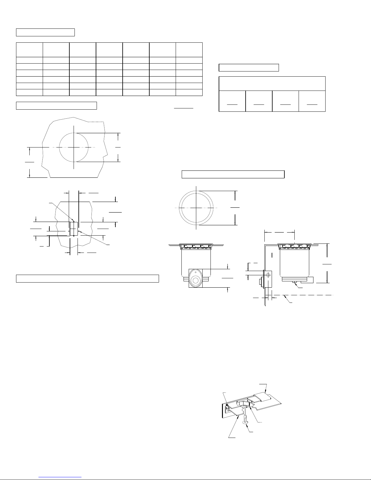
CUTOUT DETAILS
7
(178)
7 1/4
(184)
TOP CUTOUT
2 3/8
(60)
#32 DRILL
2 HOLES
4 15/16
(125)
TEMP.
RATING
75°C
75°C
75°C
75°C
75°C
INCHES
(MM)
INSTALLATION INSTRUCTIONS
BUILT-IN ROUND FOOD WARMERS
MODELS SS-4 (D)
CLEARANCES
SUGGESTED CLEARANCES FROM
UNIT TO THE NEAREST SURFACE
BACK SIDE BOTTOM FRONT
1 1
(25)
(25) (216)
8 1/2
SEE CONDITIONS OF ACCEPTABILITY BELOW
WHEN CONTROL BOX IS LOCATED BELOW THE
UNIT, FRONT CLEARANCE CAN BE 2 INCHES.
NOTE: DEPENDING ON THE INSTALLATION,
CLEARANCES CAN BE CHANGED UPON
FURTHER EVALUATIONS TO UL STANDARDS.
PRODUCT DIMENSIONS
8 1/4
(210)
NOTE: * CONTROL MUST NOT
BE MOUNTED IN THIS HIGH
TEMPERATURE AREA.
4
(102)
1 7/8
(48)
3 3/16
(81)
#19 DRILL
2 HOLES
3 7/16
(87)
1
(25)
FRONT PANEL CUTOUT
INSTALLATION INSTRUCTIONS
UNIT MUST BE INSTALLED IN AN ALL METAL COUNTER.
THE INSTALLATION OF RECOGNIZED COMPONENT UNITS
REQUIRES ADDITIONAL EVALUATIONS TO UNDERWRITERS
LABORATORIES INC. STANDARDS.
INSTALLER MUST MEET CONDITIONS OF ACCEPTABILITY
OUTLINED BELOW UPON INSTALLATION:
1. This appliance shall be installed in an all metal counter
with suitable wiring and control enclosures conforming to
national and local electrical codes.
2. Electrical component temperatures, including wiring, within
and surrounding the appliance must be monitored in the end
use installation for suitability.
3. Electrical grounding of all dead metal parts must be
reliably connected to the grounding means of the appliance
and must comply with the requirements outlined in
appropriate Underwriters Laboratories Inc. classification,
national and local electrical codes.
4. Increased clearances are required if storage of
combustible materials is in close proximity to this appliance.
5. Unit shall be accessible for servicing from the bottom.
6. The name/rating plate information shall be accessible.
7. For water and waste connections: This appliance is to
be installed to comply with the applicable federal, state or
local plumbing codes.
TO FABRICATE:
1. Lay out "cutout" dimensions on countertop and front apron.
2. Lay out and fabricate control panel holes in counter
apron using the control box as a template.
3. Cut out and/or drill holes as required in countertop
and apron.
4. Unit must be accessible for servicing from the bottom.
7 1/4
(184)
*
1
(25)
4 7/16
(113)
1/2 NPT
7/8
(22)
TO INSTALL:
1. Locate warmer and control box over countertop cutout. Pass
control through opening, then mount control electrical box to
the rear of the apron.
2. Apply a bead of silicone adhesive/sealant to the gasket
supplied on the underside of the warmer flange then seat the
warmer onto the countertop. Properly position.
3. From underneath, insert a screwdriver into "slots" on the
wellslok frame and twist the "ears" outward to secure the
flange tightly to the countertop (see detail above).
4. Mount the control panel to the front of the counter apron
using the screws supplied.
RECOMMENDATION: Units with drains should be installed
with a union for ease of service.
WARMER FLANGE
GASKET
WELLSLOK
SCREWDRIVER
COUNTERTOP
METAL SHIELD
9 1/2
(241)
(D MODELS ONLY)
WELLS/BLOOMFIELD * VERDI, NV
37122-1 REV (-)
 Loading...