

Page 1
WELLS BLOOMFIELD, LLC
2 ERIK CIRCLE, P. O. Box 280 Verdi, NV 89439
telephone: 775-689-5707
fax: 775-689-5976
www.wellsbloomfield.com
6 0 0
INSTALLATION INSTRUCTIONS
PART # 86280
RETROFIT COTHERM THERMOSTAT
Standard Brewers
Kit #86280 retrofits existing metal-shell thermostat with new hi-tech
resin-bodied thermostat.
PREPARATION:
1. Disconnect brewer from electric power and allow to cool.
Shut off water supply to brewer.
2. Remove top, front and/or back panels as required for
access to thermostat.
3. Disconnect wiring from old thermostat. Loosen two
screws holding thermostat to tank cover.
4. Remove thermobulb gland nut from tank cover. Withdraw
thermobulb from fitting. Discard thermostat assembly.
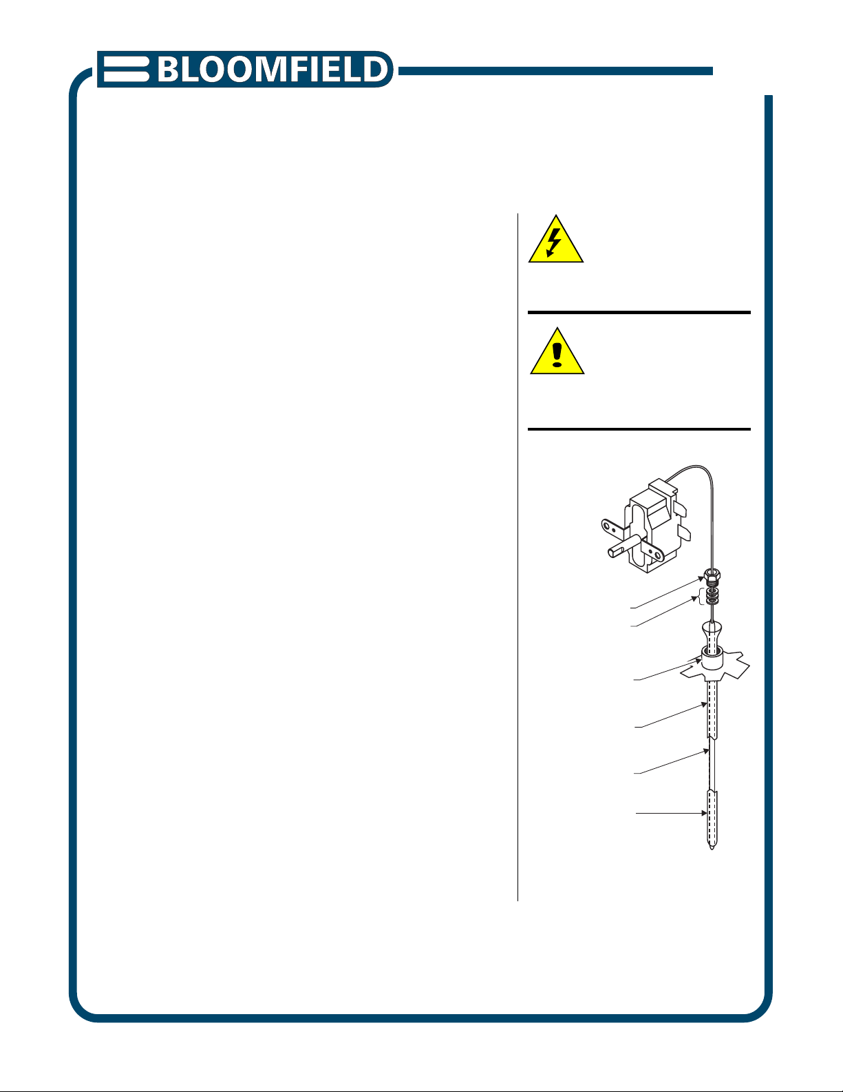
INSTALLATION:
1. Insert bulb well into fitting on tank cover. Be sure well is
fully seated in fitting.
2. Insert thermobulb into bulb well. Be sure bulb is inserted
to the extreme bottom of the well.
3. Carefully insert capillary seal components into tank fitting.
IMPORTANT: Tighten gland nut only enough to prevent
leaks. Over-tightening is not necessary.
4. Mount thermostat body to tank bracket. Reconnect wiring.
5. Reconnect brewer to electrical and water supplies.
Test brewer for proper operation.
Refer to page 2 for temperature adjustment procedure.
Upon completion, reinstall access panels.
CAUTION:
SHOCK HAZARD
Unplug brewer from electric power
before beginning this procedure.
CAUTION:
BURN HAZARD
Allow brewer to cool before
proceeding.
GLAND NUT
CAPILLARY SEAL
TANK FITTING
BULB WELL
THERMOBULB
INSERT BULB
FULLY INTO
BULB WELL
Fig. 1 Thermobulb Installation
PRINTED IN UNITED STATES OF AMERICA
p/n 76697 Rev. A ECN-13394
1 of 2
I
600 080211 cps
Page 2
CAUTION:
ELEVATION (feet above seal level)
0
500
1,000
1,500
2,000
2,500
3,000
3,500
4,000
4,500
5,000
5,500
6,000
6,500
TEMP. (ºF)
195
200
205
210
190
IDEAL
BREWING
TEMPERATURE
RANGE
MAXIMUM SAFE
TEMPERATURE
SETTING
BOILING
POINT OF
WATER
SHOCK HAZARD
These procedures involve
exposed electrical circuits.
These procedures are to be
performed by qualified
technical personnel only.
NOTE:
Optimum brewing temperature
range is 195ºF to 205ºF (90ºC
to 96ºC).
IMPORTANT:
A mechanical thermostat will
maintain temperature within
±5ºF. To prevent boiling water
in the brewer, thermostat should
be adjusted to a maximum
temperature equal to the local
boiling temperature minus 5ºF.
TEMPERATURE ADJUSTMENT
NOTE: This is a typical adjustment procedure for a standard
displacement brewer. Your exact procedure may vary depending
on the method of adding cold water to the water heater.
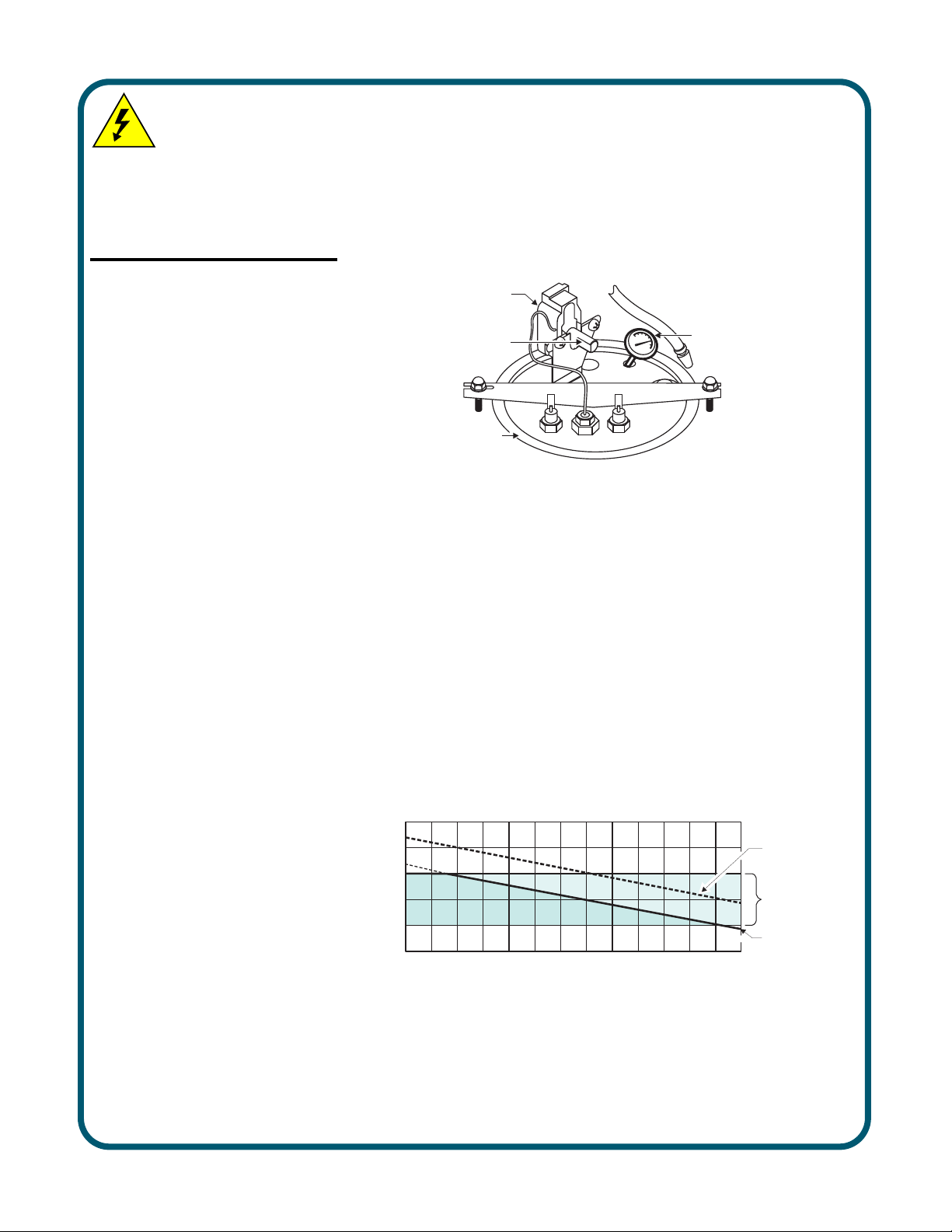
1. Disconnect brewer from electric power. Remove top panel.
2. Pull vent tube out of tank lid and insert a thermometer of
known accuracy in vent hole.
THERMOSTAT
ADJUSTING
SHAFT
VENT
DIAL-TYPE
THERMOMETER
IN VENT HOLE
TANK LID
ASSEMBLY
Fig. 2 Checking and Adjusting Brew Temperature
3. Place an empty container under brew chamber.
Reconnect brewer to electrical power. Energize brewer.
Press TANK HEATER switch ON where applicable.
4. Press BREW switch OR pour one decanter (64 oz.) of cold
water into pour-over opening. When READY TO BREW light
glows (or HEAT light goes dark), read temperature displayed
on thermometer.
5. Adjust thermostat by turning shaft;
clockwise increases temperature
counter-clockwise decreases temperature.
NOTE: 1/8 turn = approximately 10ºF.
Refer to Table 1 below for proper brewing temperature based
on altitude.
600 76697 Instr Retro Cotherm Thermo
Table 1 Boiling Temperature by Altitude
6. Upon completion, remove thermometer and reinstall vent tube.
2 of 2
 Loading...