

Page 1
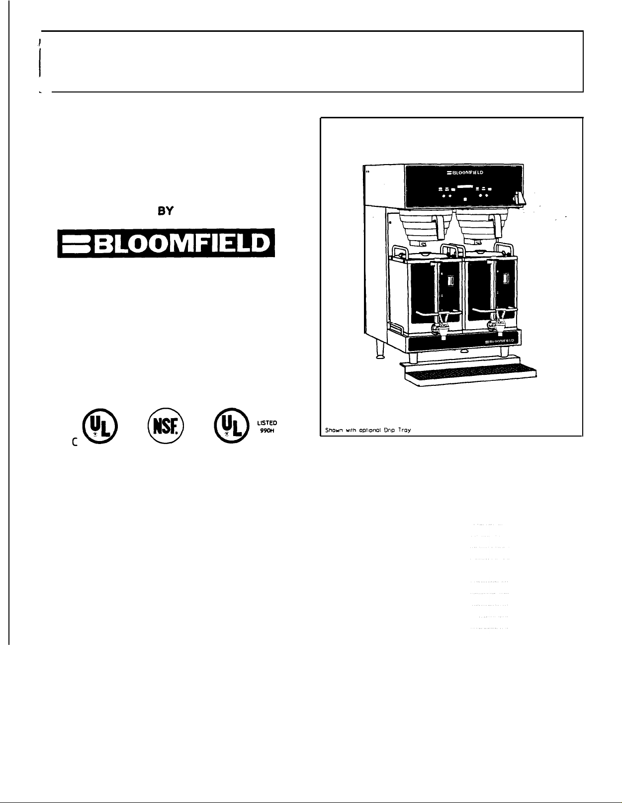
DUAL HEADED SATELLITE BREWER
1/2, 1, and 1 112 gallon brew with New Digital Display System
Bloomfield Models:
-MANUFACTURED
Bloomfield Industries
2 Erlk Circle
P. 0. BOX 280
Verdi, NV 89439
U.S.A.
Fax (800) 358-5142
Ph (702) 345-0444
SS2-BD 8 SS2-AD
Introduction
General Layout Data Sheet
Features
Warranty
Safety
Installation Instruction
Leveling the Unit
Plumber’s lnstallation Instruction
Electrician’s lnstallation Instructions
73386 Rev (A)
TABLE OF CONTENTS
Page 1
Page 2
Page 3
Page 4
Page 5
Page 6
Page 6
Page 6
Page 7
Initial installation Instructions
Brewing Instructions
Bypass Valve Adjustment
Adjustment Instructions
Exploded View (Part 1)
Parts Identification (Part 1)
Exploded View (Part 2)
Parts ldentification (Part 2)
Ordering/Service Procedure
Wiring Diagram
Printed in February, 1998
Page 7
Page 8
Page 8
Page 9
Page 10
Page 11
Page 12
Page 13
Page 14
Page 15
Page 2

INTRODUCTION
BLOOMFIELD MODELS: SS2-BD 8 SS2-AD
HI-QUALITY DUAL SATELLITE COFFEE BREWER
WITH INDEPENDENT HOT WATER DRAW FAUCET
Thank you for purchasing a Bloomfield Coffee Brewer. You will achieve maximum
performance from this unit if you familiarize yourself with- its many outstanding features.
Please take a few minutes to read through the owner’s manual. Proper installations is
very important if maximum performance and satisfaction are to be achieved.
have any difficulties, consult your nearest Bloomfield Authorized Distributor. They have
the required expertise to provide the proper advice and assistance.
Distributor is unable to assist you, please contact the factory directly.
Please be certain the electrical connections are compatible, as improper connections
could damage the Brewer and void the warranty.
Safe and satisfactory operation of your Bloomfield Brewer depends to a great extent
upon its proper installation.
in accordance with these printed instructions and applicable electrical codes. The
performance and safety of the Brewer can be greatly impaired if it is altered in any
way, or if installation deviates from the instructions printed herein, and will not
be covered under any warranty service agreement.
This Coffee Brewer must be installed without alteration and
If the Bloomfield
If you
.
This Bloomfield Brewer has been designed with adjustment flexibility to cover a
wide spectrum of customer needs.
1
r
Page 3
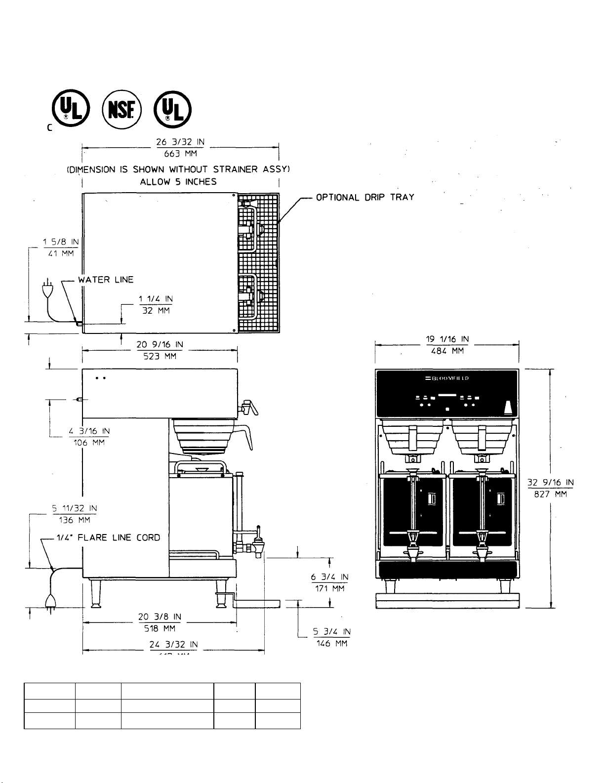
GENERAL LAYOUT DATA
BLOOMFELD 1/2, 1 & 1 1/2 GALLON
DUAL SATELLITE COFFEE BREWER
MODEL: 882 SERES
ELECTRICAL SPECIFICATIONS
MODEL WATTS VOLTS HZ AMPS
SS2-BD 6155 120/240 50/60 27.0
SS2-AD 5655 120/208 50/60 27.0
2
Page 4

FEATURES
MODELS SS2-AD & SS2-BD DUAL SATELLITE COFFEE BREWER WITH HOT WATER FAUCET,
manufactured by Bloomfield industries Inc., Is designsd to brew 3 portions of 1/2, 1 & 1 1/2
Gallons of coffee on each side at the press of a switch and to hold hot beverage at the
correct temperature for serving.
0
Operates on 1201240 Volts, 30 Amps, 6155 Watts. 50/60 Hz service for SS2-BD and
120/208 Volts, 30 Amps, 5655 Watts, 50/60 Hz service for SS2-AD.
0
Requires a water flow rate of 1 gallon (4 Itr) per minute at a minimum pressure of 30
PSI. (2.0 bars).
0,
Dual 3 Portion Brew (1/2 ,1 & 1 1/2 Gallons) at the press of a switch.
0
Consistent extraction on all 3 portions of brew through various flow systems which
includes unique hot water bypass system.
0
Absence of any hot surfaces.
0
Unit will NOT Brew unless a Satellite Is in place.
0
Hot water faucet mounted on the front of the brewer allows draw off of hot water for
hot beverages or for rinsing purposes at anytlme without affecting the coffee brew
volume.
0
Adjustable non-skid rubber feet on brewer for easy leveling.
0
Exclusive “water spray disc’ where water flows gently and uniformly over the coffee grounds,
causing a floating action and complete saturation of all coffee grounds.
0
Adjustable coffee quality timer light which flashes at end of approved coffee holding time.
0
OPTIONAL Drip Tray.
0
Fully Electronically Controlled:
0
Precise Temperature Control
0
Precise Volume and Timing Control
o Each volume Individually programmable if required
0
After hours mode with saves energy and increases componet life
0
Safety feature Includes monitoring of each operation
0
Double Brew prevention
0
Brew count Information
0
Teflon color coded wiring, keyed to color tabs at connection points.
0
Unit size requires minimal counter space.
0
OPTIONAL Satellite Docking Station
0
UL, CUL & NSF Listed (UL & CUL: E9253) (NSF: Standard 4)
0
Manufactured in USA
3
Page 5

FEATURES
MODELS ss2-AD & ss2-BD DUAL SATELLITE COFFEE BREWER WITH HOT WATER FAUCET,
manufactured by BloomfIeld Industries Inc.,
Gallons of coffee on each side at the press of a switch and to hold hot beverage at the
correct temperature for servlng.
0
Operates on 1201240 Volts, 30 Amps, 6155 Watts, 50/60 Hz service for SS2-BD and
1201208 Volts, 30. Amps, 5655 Watts, 50/60 Hz service for SS2-AD.
0
Requires a water flow rate of 1 gallon (4 Itr) per minute at a minimum ‘pressure of 30
PSI. (2.0 bars).
Is designed to brew 3 portions of 1/2, 1 & 1 1/2 _
0.
0
0
0
0
0
0
0
0
0
Dual 3 Portion Brew (l/2 ,1 8 1 1/2 Gallons) at the press of a switch.
Consistent extraction on all 3 portions of brew through various flow systems which
includes unique hot water bypass system.
Absence of any hot surfaces.
Unit will NOT Brew unless a Satellite is in place.
Hot water faucet mounted on the front of the brewer allows draw off of hot water for
hot beverages or for rinsing purposes at anytime without affecting the coffee brew
volume.
Adjustable non-skid rubber feet on brewer for easy leveling.
Exclusive “water spray disc’ where water flows gently and uniformly over the coffee grounds,
causing a floating action and complete saturation of all coffee grounds.
Adjustable coffee quality timer light which flashes at end of approved coffee holding time.
OPTIONAL Drip Tray.
Fully Electronically Controlled:
0
Precise Temperature Control
o Precise Volume and Timing Control
o Each volume individually programmable if required
o After hours mode with saves energy and increases componet life
o Safety feature includes monitoring of each operation
o Double Brew prevention
o Brew count information
0
Teflon color coded wiring, keyed to color tabs at connection points.
0
Unit size requires minimal counter space.
0
OPTIONAL Satellite Docking Station
0
UL, CUL & NSF Listed (UL & CUL: E9253) (NSF: Standard 4)
0
Manufactured in USA
3
Page 6

WARRANTY POLICY
All electrical products manufactured by Wells/Bloomfield are warranted against defects
In material and workmanship by our authorized service agents with:
0
One (1) year replacement part warranty
0
One (1) year on labor
0
All genuine Wells/Bloomfield replacement parts are warranted for ninety (90) days
from date of purchase on non-warranty equipment.
‘only to replacements of the defective part.
Any use of non-genuine Bloomfield
parts completely voids any warranty. .
Labor includes the cost of travel time and Is limited to a sixty (60) mile radius
(or up to a maximum of one hour) to the nearest authorized service agency or one of
It’s sub-service agencies.
This service will be provided on the customers premises
for non-portable models. All labor shall be performed during regular working hours.
Overtime premium will be charged to the buyer.
In addition to this warranty policy are the following exceptions:
Dispensers (i.e., tea and coffee) carry ninety (90) day parts replacement only.
A.
This parts warranty is limited
‘-
Warranty does not Include any coverage for:
Resetting the safety thermostats, circuit breakers, overload protectors, or fuse
replacements unless warranted conditions are caused.
All problems due to operation at voltage other than specified on equipment
nameplates - conversion to voltage other than marked on unit Is the customer’s
responsibility.
All problems due to electrical connections not made in accordance with electrical
code requirements and wiring diagrams supplied with the equipment.
All problems due to inadequate water supply, such as fluctuating, high or low
water pressure, etc.
All problems due to mineral/calcium deposits, or contamination from chlorides
and or chlorines. De-liming Is considered a preventative maintenance function
and not covered by warranty.
Replacement of Items subject to normal wear which Include such Items as baskets,
grids, switch panels, and thermocouples.
adjustment of electronics or replacement of fuses.
Installation, labor, and job check-outs are not considered warranty.
.
Normal maintenance functions Including
Page 7

THIS WARRANTY IS THE COMPLETE AND ONLY WARRANTY, EXPRESS OR IMPLIED IN LAW
OR FACT, INCLUDING BUT NOT LIMITED TO WARRANTIES OF MERCHANTABILITY OR FITNESS
FOR ANY PARTICULAR PURPOSE, AND/OR FOR DIRECT, INDIRECT OR CONSEQUENTIAL
DAMAGES IN CONNECTION WITH WELLS/BLOOMFIELD PRODUCTS. This warranty is void if it
is determined that upon inspection by an authorized Wells/Bloomfield dealer/distributor that
the equipment has been modified, misused, misapplied, Improperly installed, or damaged In
transit or by fire, flood or act of nature.
has been removed or service is performed by unauthorized personnel..
It also does not apply if the serial nameplate
NOTE:. A Warranty Statement and Complete Service Agency Listing with Warranty exclusions
is provided with each unit.
BREWER WARRANTY IS VOID IF:
Other than genuine Bloomfield replacement parts are used.
Brewer is connected to voltage that doesn’t agree w/specifications on serial plate.
Recommended Bloomfield servicing procedures are not followed.
_
SAFETY
Knowledge of proper procedures is essential to the safe operation of electrically energized
equipment.
potential hazards, the following 4 signal words are used throughout this chapter.
DANGER
severe personal injury, death, or substantial property damage in the event the
statement is ignored.
in accordance with generally accepted product safety labeling guidelines for
- Danger is used to indicate the presence of a hazard which will cause
WARNING - Warning is used to Indicate the presence of a hazard which can cause
severe personal injury, death, or substantial property damage in the event the
statement is ignored.
CAUTION- Caution is used to Indicate the presence of a hazard which will or can
cause minor personal injury, or property damage in the event the statement Is
ignored.
NOTE
information which is important, but not hazard related.
NOTE
hardware.
Hazard Communication Standard (HCS)
the use of chemical products.
bold face letters followed by the abbreviation (HCS). See the Hazard Communication
Standard (HCS) Manual for the appropriate Material Safety Data Sheet(s) (MSDS).
- Note Is used to notify personnel of installation, operation or maintenance
- This piece of equipment is made in the USA and has American sizes on
All metric conversions are approximate and can vary in size.
- The procedures in this chapter may include
These chemical products will be highlighted with
5
Page 8

INSTALLATION INSTRUCTION
READ THIS COMPLETELY BEFORE STARTING THE INSTALLATION
CAUTION: DO NOT plug In or energize this unit until lnstallation lnstructions are read
A
and followed.
To enable the installer to make a quality installation and minimize installation time, the
following suggestions and tests should be done before the actual unit installation is
begun. .
Damage to the Brewer will occur If the Instructions are not followed.
LEVELING THE UNIT
Set Coffee Brewer in operating location and level.
that the Brewer be level when It is standing In its proper operation position. A spirit level
should be placed on the top of the Brewer, at the edge, as a guide when making level
adjustments.
that support the unit.
CAUTION:
will result In movement of Brewer which can cause personal Injury and/or damage to
the Brewer.
Level the unit from left to right and front to back by turning the adjustable feet
Rubber feet must be Installed on each leg of the unit. Failure to do so
It is very important for proper operation
PLUMBER’S INSTALLATION INSTRUCTION
must be installed to comply with the Basic Plumbing Code of the
Building Officials and Code Administrators International, Inc (BOCA) and the Food Service
Sanitation Manual of the Food and Drug Administration. (FDA)
Flush water line before connecting to Brewer.
WATER line.
Bloomfield recommends 1/4" copper tubing for installation of less than 25 feet and
3/8” for more than 25 feet from the 1/2” water supply line.
water line connection.
Brewer should be connected to COLD
Do Not use a saddle valve for
A water shut-off valve should be installed on the incoming water line in a convenient
location.
The Brewer must be installed on a water line with a flowing pressure between 30 PSI and
70 PSI.
does not fall into this range, varies greatly, or exceeds 70 PSI at anytime.
A
We recommend the use of a Water Strainer to help prevent deposits in the Brewing System.
A pressure regulator must be installed in the water supply line, If water pressure
CAUTION: If local codes require a back flow preventor, a water hammer arrestor
(Part no. 9012-44) MUST be Installed between the back flow preventor and the Brewer.
The Back flow preventor should be Installed as close to the Incoming water source
as possible. Failure to comply could cause damage to the Brewer.
8
Page 9

ELECTRICIAN’S INSTALLATION INSTRUCTIONS
WARNING ELECTRICAL SHOCK HAZARD: Brewer must be properly grounded to
prevent possible shock hazard.
a ground.
The unit requires a dedicated power source capable of supplying: 1201240 Volt A.C. 50/60
Hertz, (4) wire, Single Phase, 30 Amp Service for Model SS1-BD and 1201206 Volt A.C. 50/60
Herts, (4) wire, Single Phase, 30 Amp Service for Model SS1-AD.
Electrical shock will cause death or serious Injury.
D0 NOT assume a plumbing Iine will provide such
INITIAL INSTALLATION INSTRUCTIONS..
CAUTION: Initial. Installation should be performed by a qualified Installer or qualified
service technician.
Electrician’s and Plumber’s Instructions should be followed carefully before proceeding
with initial Installation Instructions.
Be sure all electrical and plumbing connections are secure and leak proof.
DO NOT CONNECT POWER TO UNIT WITH SATELLITES IN PLACE.
Improper Installation will damage the Brewer and void warranty. .
With Power Connected, “Bloomfield” will display momentarily and Brewer will “Beep”.
Press Power Switch.
NOTE:
Fill time for tank is approximately 13 minutes, unit fills tank until water level is 1/8”
above level probe tip.
a “NO WATER SENSED” error is displayed.
NOTE:
instruction.
and debris.
When tank is filled ,
Insert Satellites.
Allow 30 minutes for initial water heat up.
When tank water is up to desired Brew temperature, the “Tank Heater” LED will turn off.
NOTE:
the inlet Solenoid is actuated. This prevents volume differances to the initial Brew caused
by water expansion.
NOTE:
The Brewer is now ready for use.
Inlet solenoid will energize and tank will begin to fill. “Filling’ will display.
If tank is not full within 20 minutes, the unit will shut down and
if a ‘No Water Sensed’ error is displayed, unplug Brewer. See plumber’s installation
If plumbing and water pressure is correct, check inlet solenoid for function
“Tank Heater’ LED will turn on and “HEATING” is displayed.
Check Satellite alignment and make sure Satellite LEDS are on.
Time will vary with incoming water temperature.
Before brewing and after initial Heat-up, draw water from the Hot Water Faucet until
Brewer will not function unless a Satellite is properly positioned on the Brewer.
3
7
Page 10

BREWING INSTRUCTIONS
Select Portion 1/2, 1 or 1 1/2 gallon.
Place a single filter paper in Brew Chamber and add Coffee.
ounce of Coffee per quantity Brew)
stop location.
Press Brew Switch to start brewing.
preset at factory
Press the “Brew Stop’ switch if for any reason there is a need to stop the brewing cycle
before its completion.
flash.
Check Brew Volume.
adjustments in the Volume.
Repeat for all portions.
NOTE: Hot water bypass is factory set to energize only in the 1 1/2 gallon position. However,
it can be energized in all positions, see PROGRAM MANUAL.
Also removing the Satellite will stop the brew cycle.
- to change see PROGRAM MANUAL.
This stops water flow to the Brew Chamber and Satellite light will
See “Changing Brew Settings” on the PROGRAM MANUAL for any
Slide Brew basket into rails, pushing it to full back
This starts the Quality Timer. Light ‘for each Satellite
(see below for recommended
BYPASS VALVE ADJUSTMENT
Disconnect Brewer from power source.
Remove Satellites, Brew Chamber and plug buttons on Front Panel
.
NOTE:
the two plug button holes.
With an alien wrench or flat screwdriver, turn bypass adjustment clockwise to decrease, counterclockwise to increase volumn.
percent.
Replace plug buttons and brew chambers and connect brewer to power source.
Replace Satellites, select portion and check volumn.
NOTE:
to be adjusted, see PROGRAM MANUAL.
RECOMMENDED COFFEE AMOUNT per BREW
To Brew 1/2 Gallon, use 2.25 oz (64 g)
To Brew 1 Gallon, use 4.50 or (128 g)
To Brew 1 1/2 Gallon, use 8.40 oz (240 g)
NOTE:
Bypass valve adjustments are behind front panel and are reached through
Adjust in small increments. 1/32’ can change volumn serveral
Any adjustment to the bypass valves will change the total volumn. Brew time will have
This may vary depending on the type of Coffee and individual taste requirements.
WARNING Make sure water has completely stopped dripping before removing the
Brew Chamber.
Hot water in the Brew Chamber will cause serious burns.
a
Page 11

Pressing the Item key brings the user to the settings for volume #2, #3, and so on until #6. Recall that volumes #1,2 and 3
correspond to the ½ gallon, 1 gallon and 1½ gallon selections for the left satellite, and that volumes #4, 5 and 6 correspond to the ½
gallon, 1 gallon and 1½ gallon selections for the right satellite.
Setting Symmetric Brew Settings
After completing the volume settings for the left batch, or if the left batch settings are skipped, we come to the option:
• Set L=R? Y/N Selecting Y will copy all of the left side settings to the right side.
The next menu item is Change R. Vols? which can take you into right side batch settings, that can be programmed different from
left side.
Changing the Timer for Coffee Quality Indication
The coffee quality indicators (satellite LEDs) will turn on once a brew has been completed, and will stay on for a specified amount
of time before flashing. A flashing satellite LED is an indication that the coffee should be re-brewed.
• QualityTime: 30m
This time is adjustable from 30 minutes to 180 minutes.
If the satellite is removed or reinstalled, the LED will turn off until another brew of coffee is made.
NOTE: If a brew is cancelled, the Satellite indicator will flash since the amount of time to properly brew was not
correct.
After-Hours Options
The After-Hours mode is intended to increase the temperature range in which to maintain the water. This will reduce the rate in
which the relay contacts will wear out. After hours mode is entered after an adjustable amount of time. First, a menu item is
displayed to enable/disable After -Hours:
• After -Hours: On
By default, After -Hours is enabled. After-Hours can be disabled/re-enabled using the (+) or (-) key. If After Hours is Off
(disabled), then the following menu item is skipped when the Item key is pressed, moving on to Timer menu functions. If After Hours is enabled, the delay time after the last brew before entering into After -Hours mode is displayed:
• Delay Time: 3h
The default delay time is 3 hour s, but is adjustable to between 1 hour and 5 hours. Adjusting the
Timer
To save energy and extend component life, a timer is used to select the day and time in which the brewer will automatically shutoff and restart. It is primarily a management decision on when the brewer will be used. By default, the timer is turned off:
9
Page 12

10
Page 13

EXPLODED VIEW (Part
SS2 SERIES
2)
12
Page 14

PARTS IDENTIFICATION
(SS2 TANK ASSY & PLUMBING)
ITEM SERVICE #
40 8541-120 VALVE SOLENOID 120V 1
41 8043-5 STRAP HOLD DOWN ASSY 1
42 8043-47 SCREW PAN 10-32 X 1 LG 1
43 8043-12 GASKET SPRAY HEAD 1
44 8812-57 FITTING UNION 1/4X1/4 1
45 8710-10 NUT HEX BR 7/16-20X1/8 1
46 8572-20 TUBE INLET ASSY 1
47 8551-53 WASHER SS 035X7/16IDX3/40D 1
48 8783-1 FAUCET HOT WATER 1
49 9102-8 ELBOW 1/4 FPT/HOSE 1
50 82114 PROBE 8783MCD 1
51 82115 GROMMET 1/4 ID TRANSLUCENT 2
52 82390 GROMMET 375 ID TRANSLUCENT 1
53 83385 TUBE INLET 1
54 83152 ELBOW SPRAYER 1/4 ID 2
55 TANK WLD ASSY SS2 1
56 83287 ELEMENT 3000W 230V 2
57
58 8706-160 CONNECTOR 1
59 83309 GASKET TANK HEATER SS2 2
60
61 83311 FILL TUBE 90DEG BEND SS2 1
62 83312 THERMOSTAT HI-LI MIT DBL POLE 1
63 83318 PLUG TANK LID 510 DIA A 2
64 83319 PLUG TANK LID 298 DIA 1
65 83320 PLUG TANK LID 687 DIA 1
66 83325 TANK LID WELDED ASSY SS2 1
67 83314 TUBE TANK TO VALVE SS2 2
68 67662 FTG BARB 3/8 TO HOSE 1
69 66575 VALVE SHUTOFF DRAIN 1
70 83379 FTG ADAPTOR 3/8 TO 5/8-18 1
71 83380 TUBE ASSY 3/8 COPPER DRAIN 1
72 83381 KIT DRAIN VALVE ASSY 1
73 83359 WASHER FLARE TANK DRAIN 1
74 83358 PLUG TANK DRAIN 1
75 83357 NUT TANK DRAIN PLUG 1
76 6043-506 NUT ACR SS 8-32 2
77 8043-11 ELBOW OUTLET 2
78 83384 TUBE VENT EXTENSION 2
79 8783-23 TUBE VENT 1
80 82729 VALVE DISPENSING ADJUST 4
81 83382 TUBE TANK TO FAUCET 1
82 BRACKET BYPASS VALVE 2
83 82148 WASHER LOCK 1
84 65001 SCREW 10-32 X 1/2 4
85 55485 NUT 1/4-20 (PACK OF 100) 1
86 D20002-3 SCREW 10-32 2
87 82741 FTG STAND PIPE 2
88 8812-70 WASHER BEVELLED 2
89 8043-30 WASHER SI LI CONE 2
90 83147 WASHER GYLON 2
91 82739 NUT STAND PIPE 2
92 83388 VALVE BYPASS ADJUSTMENT 2
93 83313 PROBE THERMISTOR 1
94 83414 SHIELD HI-LI MIT THERMOSTAT 1
95 83415 NUT 6-32 X 1 LG 2
BRACKET SOLENOID VALVE SS2 1
BRACKET BYPASS VALVE TNK SS2 2
DESCRIPTION QTY
13
Page 15

WIRING DIAGRAM
(MODELS:
SS2-BD & SS2-AD)
I I I I
I -
1 ma
I
I
15
 Loading...