

Page 1
672
OWNERS MANUAL
for
SS2 - SERIES
DUAL SATELLITE
COFFEE BREWERS
with
ELECTRONIC
PROGRAMMABLE
CONTROL
and
INTERNALLY HEATED
SATELLITE SERVERS
MODELS:
9520 9520FB
9521 9521FB
Includes:
Installation
Operation
Use & Care
Servicing Instructions
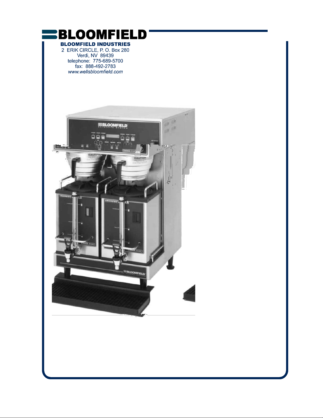
Model 9520 Dual Satellite Brewer
p/n 74345 Rev. J ECN-12887 M672 050825 cps
with optional
3901 Drip Tray
PRINTED IN UNITED STATES OF AMERICA
Page 2

NOTE: For your protection, please note that equipment in
this shipment was carefully inspected and packaged by
skilled personnel before leaving the factory. Upon acceptance of this shipment, the transportation company assumes
full responsibility for its safe delivery.
IF SHIPMENT ARRIVES DAMAGED:
1. VISIBLE LOSS OR DAMAGE: Be certain that any
visible loss or damage is noted on the freight bill
Page 3
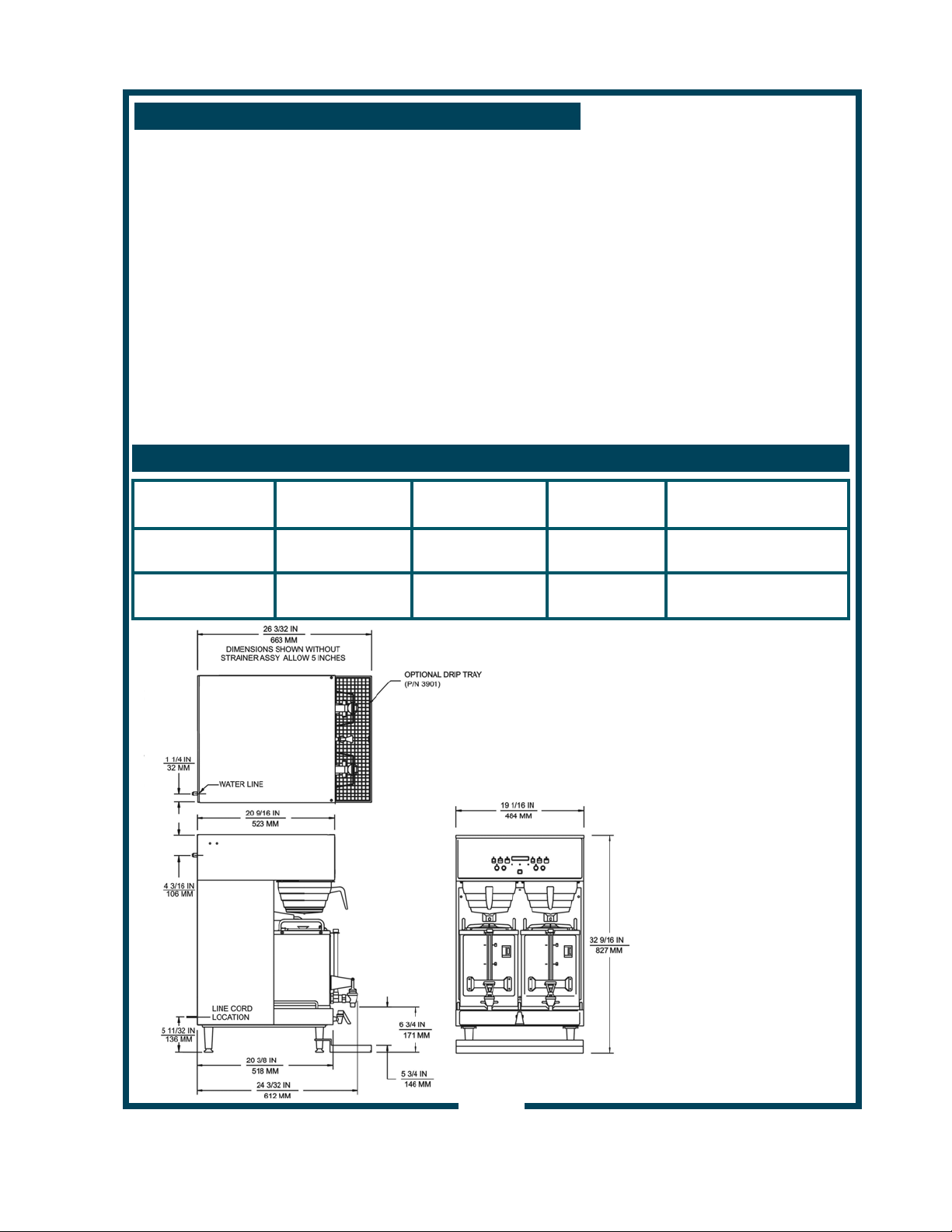
TABLE OF CONTENTS
Thank You for purchasing this
WARRANTY STATEMENT xi
SPECIFICATIONS 1
FEATURES & OPERATING CONTROLS 2
PRECAUTIONS & GENERAL INFORMATION 4
AGENCY APPROVAL INFORMATION 4
INSTALLATION 5
OPERATING INSTRUCTIONS 7
CLEANING INSTRUCTIONS 10
PROGRAMMING INSTRUCTIONS 12
TROUBLESHOOTING SUGGESTIONS 17
SERVICING INSTRUCTIONS 18
EXPLODED VIEWS / PARTS LISTS 20
WIRING DIAGRAM 24
Bloomfield Industries appliance.
Proper installation, professional
operation and consistent
maintenance of this appliance will
ensure that it gives you the very
best performance and a long,
economical service life.
This manual contains the
information needed to properly
install this appliance, and to use,
care for and maintain or repair the
appliance in a manner which will
ensure its optimum perf ormance.
SPECIFICATIONS
MODEL VOLTS WATTS AMPS POWER
9520
9520FB
120/208 VAC
50/60 Hz 1ø
5655W 27A not provided
CORD
9521
9521FB
672 74345 Owners Manual Dual Satellite 9520/9521
120/240 VAC
50/60 Hz 1ø
6680W 28A not provided
Model 9520FB shown
Others are similar
1
Page 4
FEATURES AND OPERATING CONTROLS
Fig 1. SS-2 Satellite Brewing System Features & Operating Controls
2
Page 5

FEATURES AND OPERATING CONTROLS (continued)
Brewer
Adjustable Legs
Brewing Controls
Connector
Digital Readout
Bypass Nozzle
Hot Water Faucet
Nameplate
Power Key
Power Switch
Brew Chamber
Brew Chamber
Wire Rack
Satellite
Brew-Thru Lid
Connector
Handles
Nameplate
Serving Faucet
Sight Glass
Drip Tray (optional)
Allows brewer to be leveled. Also allow clearance for cleaning
underneath brewer.
Start or stop brew and select brew volume. Right and left section
are independent. Also, used to program brewer in programming
mode.
Connects to satellite. Allows satellite heater to be energized.
Allows brewer to sense that a satellite is in place.
Displays information pertaining to brew cycle and status.
Displays programming information in programming mode.
Dilution water flows into satellite from here.
Hot water dispensed here. Mounted in base on FB models.
Lists manufacturer, model and serial number.
Also lists voltage and wattage rating of brewer.
Controls brewer ON MODE and OFF MODE.
Located on lower right rear of brewer. Turns main power to
brewer ON or OFF .
Holds coffee grounds during brew cycle.
Holds paper filter and coffee ground s in pr oper position in brew
chamber.
Allows entry of brewed coffee and dilution water into satellite.
Minimizes splashing in the event satellite is tipped.
Connects to brewer. Allows heater to be energized. Allows
brewer to sense that a satellite is in place.
Allow the satellite to be safely carried.
Lists manufacturer, model and serial number.
Also lists voltage and wattage rating of satellite.
Fresh coffee dispensed from satellite here.
Check the level of coffee remaining here.
Optional drip tray catches drips and spills from serving faucet.
Easily removed for cleaning.
672 74345 Owners Manual Dual Satellite 9520/9521
3
Page 6
GENERAL INFORMATION AND PRECAUTIONS
WARNING:
Electric
Shock hazard
All servicing requiring
access to non-insulated
electrical components
must be performed by a
factory authorized
technician.
DO NOT open any
access panel which
requires the use of tools.
Failure to follow this
warning can result in
severe electrical shock.
CAUTION:
Burn Hazard
Surfaces of this brewer
can be hot and can
cause burns on contact.
This appliance is intended for use in commercial establishments
only.
This appliance is intended
for human consumption. No other use is
by the manufacturer or its agents.
Operators of this appliance must be familiar with the appliance use,
limitations and associated restrictions. Operating instructions must be
read and understood by all persons using or installing this appliance.
Cleanliness of this appliance is essential to good sanitation. Read and
follow all included cleaning instructions and schedules to ensure the
safety of the food product.
Surfaces of the brewer, brew basket and satellite can be hot to the
touch, and may cause burns on contact.
Disconnect the brewer from electrical power before performing any
maintenance or servicing.
DO NOT submerge satellites in water.
DO NOT splash or pour
water over, onto or into any controls, control panel or wiring.
Any procedure which requires the use of tools must be performed by a
qualified technician.
This manual is considered to be a permanent part of the appliance.
This manual and all supplied instructions, diagrams, schematics, parts
breakdown illustrations, notices and labels must remain with the
appliance if it is sold or moved to another location.
This appliance is made in the USA. Unless otherwise noted, this
appliance has American sizes on all hardware.
to brew hot beverage, specifically coffee,
recommended or authorized
672 74345 Owners Manual Dual Satellite 9520/9521
E9253
E9253
STD 4
AGENC Y APPROVAL I NFORMATIO N
This dual satellite brewing system is listed under E9253
and listed under E9253.
This dual satellite brewing system meets NSF Standard 4 only when
installed and maintained per the instructions in this manual.
4
Page 7
INSTALLATION INSTRUCTIONS
INSTALL LEGS
The brewer is provided with adjustable legs and rubber feet. Be
sure the legs are securely screwed into the base of the brewer, and
that the rubber feet are properly installed.
LEVEL THE UNIT
The adjustable legs allow the brewer to be leveled. Set the brewer
in its ultimate operating location and check for level with a spirit
level Adjust the brewer for level from front-to-rear, and from sideto-side. Be sure all four feet rest firmly on the counter.
PLUMBER’S INSTALLATION INSTRUCTIONS
IMPORTANT:
This equipment must be installed in accordance with the Basic
Plumbing Code of the Building Officials and Code Administrators
International (BOCA), and the Food Service San itation Manual of
the Food and Drug Administration (FDA). Also, this equipment installation must comply with all local codes and ordinances.
Brewer must be installed on a water line with a full-flow pressure
between 20 psi and 90 psi.
NOTE: If water pressure varies greatly, or exceeds 90 psi at any
time, a water pressure regulator must be installed. Plumbing
installer must supply the regulator.
Brewer must be connected to a potable water supply. Bloomfield
recommends not less than 1/4” copper tubing for installations of 12’
or less, and not less than 3/8” copper tubing for installations
exceeding 12’. Brewer must be connected to a COLD water line.
NOTE: DO NOT use a saddle tap for this water line connection.
A shut-off valve must be installed between the main water supply
and the brewer. Plumbing installer must supply the shut-off valve.
A 1/4-turn ball valve is recommended.
Bloomfield recommends the use of a water strai n er to help prevent
deposits in the brewing system.
Flush the water line before connecting to the brewer.
ELECTRICIAN’S INSTALLATION INSTRUCTIONS
Brewer requires a dedicated single-phase circuit:
Model 9520 120/208 Volt AC, 50/60 Hz 3-Wire + gnd
5655 Watts 30 Amps
Model 9521 120/240 Volt AC, 50/60 Hz 3-Wire + gnd
6156 Watts 30 Amps
672 74345 Owners Manual Dual Satellite 9520/9521
NOTE:
To enable the installer to make
a quality installation and to
minimize installation time, these
tests and suggestions should
be completed before the actual
installation is begun.
CAUTION:
Hazard from
Unstable Equipment
Rubber feet must be installed
on each leg of the brewer.
Legs must be adjusted so that
all four feet rest firmly on the
counter. Failure to properly in stall the feet can result in movement of the brewer, which can
cause personal injury and/or
damage to the brewer.
SCREW INTO
BREWER
FRAME
Fig. 2 Adjustable Legs
ADJUST
FOR
HEIGHT
ATTACH
RUBBER
FEET
CAUTION:
Electric Shock
Hazard
Brewer must be properly
grounded to a reliable earth
ground to prevent possible
shock hazard. Do not assume
a plumbing line will provide
such a ground. Electrical shock
may cause serious injury.
5
Page 8

INSTALLATION INSTRUCTIONS (continued)
IMPORTANT:
Initial set-up must be performed
by a qualified installer or
qualified service technician.
Improper set-up will damage the
brewer and void the warranty.
DO NOT CONNECT POWER
TO BREWER WITH
SATELLITES IN PLACE.
NOTE: If “NO WATER
SENSED” error message is
displayed:
* Disconnect brewer from
electrical power.
* Review Plumber’s
Installation Instructions
* Check inlet solenoid for
debris and verify proper
operation
NOTE: Brewer will not operate
unless a satellite is properly
positioned on the brewer.
INITIAL SET-UP INSTRUCTIONS
Plumber’s and Electrician’s installation procedures must be
completed before proceeding with the set-up.
Be sure all electrical connections are secure, and that all
plumbing connections are secure and leak-proof.
1. CHECK BREWER FOR PROPER CONFIGURATION
Make sure spray disk gaskets are in place INSIDE of spray
heads.
Make sure spray disks are properly installed.
Check hot water faucet for proper operation and leaks.
2. START BREWER OPERATION
With the satellite servers removed, press the POWER
SWITCH to ON.
When power is first applied to the brewer, the display will
read “BLOOMFIELD” briefly, and a “beep” will sound.
Press the POWER key on the front panel. The inlet valve will
energize and the tank will begin filling. The display will read
“Filling…” Fill time for the tank is approximately 13 minutes.
If water is not sensed at the water level probe within 20
minutes, the brewer will shut down and the display will read
“NO WATER SENSED” error message.
When tank has filled, TANK HEAT LED will glow and display
will read “Heating…”.
Slide satellites into position. Make sure satellites are properly
aligned and the SATELLITE LEDs are lit.
Allow 30 minutes for initial water heat-up. Time will vary with
incoming water temperature. When the tank water is up to
the Precise Temperature for Brewing™, the TANK HEAT
LED will turn off.
3. FINAL CHECKS
After initial heat-up and before brewing, draw water from the
hot water faucet until the inlet solenoid actuates. This will
prevent volume differences to the initial brew caused by
water expansion.
Verify brew water temperature. It should be 198ºF ±5ºF.
Check and adjust water delivery volumes.
Disconnect brewer from electrical power. Inside top of the
brewer for leaks. Reassemble brewer and reconnect power.
672 74345 Owners Manual Dual Satellite 9520/9521
6
Page 9
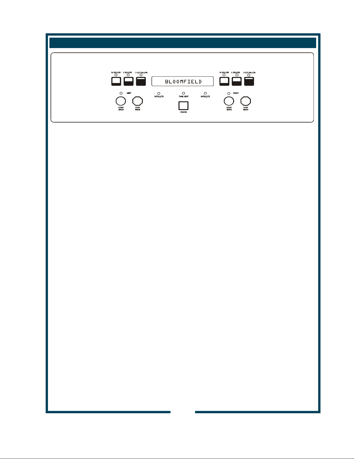
Fig. 3 Control Panel
OPERATING INSTRUCTIONS
GETTING STARTED
Check the brewer and satellites:
Check that the brewer is clean and the drip tray (if used)
is empty.
Check that the satellites are empty and clean with lids
properly installed.
Check the spray heads:
Remove the brew chambers. Check the spray heads. Verify
that the spray disks are clean and properly installed. Verify
that the gaskets are properly installed inside the spray heads.
Check the brew chambers:
Check that the brew chamber is clean.
Check that the wire basket is properly installed in the
brew chamber.
DAILY START-UP
Press POWER KEY to enter ON mode:
Brewer water tank will begin filling. The message FILLING
will be displayed.
When the tank is full, TANK HEAT LED will glow, and the
message HEATING is displayed indicating that the tank
heater is ON.
When the tank is filled and up to temperature, time and date are
displayed. The brewer is ready to operate.
672 74345 Owners Manual Dual Satellite 9520/9521
NOTE:
If water is not sensed at the
water level sensor within 20
minutes:
Heater will be disabled
Error message NO WATER
SENSED will be displayed
7
Page 10

OPERATING INSTRUCTIONS (continued)
Fig. 4 Operating Controls
Fig. 5 Brew Basket
CAUTION:
Burn Hazard
Basket and contents are
hot to the touch and may
cause burns on contact.
BREWING COFFEE
Prepare the Brew Baskets:
Make sure the wire rack is properly installed in each brew
chamber.
Insert one (1) Bloomfield paper filter into each brew chamber.
Make sure the filter is p roper ly supported by the wire rack.
Add a measured amount of grounds to each brew basket.
Gently shake the basket to level the grounds.
Slide one brew chamber under each brew head.
Insert Satellites:
Slide one satellite under each brew chamber until it is fully
seated.
When the satellite is properly installed, SATELLITE LED for
left or right side will glow.
Select Brew Volume:
Press either the 1/2 GALLON , 1 GALLON or 1-1/2 GALLON
key. The corresponding LED will glow.
Start the Brew:
Press either the right or left START BREW key. The LED for
the selected side will glow.
NOTE: The brew can be cancelled at any time by pressing
the BREW STOP key.
At the end of the brew, the brewer will beep. When the TANK
HEAT LED goes out, the brewer is ready to run another brew
cycle.
Empty the Brew Basket:
Discard the grounds and the paper filter. Rinse the brew
chamber under clear water.
Page 11

OPERATING INSTRUCTIONS (continued)
9
Page 12

CLEANING INSTRUCTIONS
CLEANING INSTRUCTIONS
CAUTION:
Burn Hazard
Brewing and serving
temperatures of coffee are
extremely hot.
Hot coffee will cause
serious skin burns.
WARNING:
Electric
Shock
Hazard
DO NOT immerse or
submerge satellites. Fluid
may saturate the insulation
and short-circuit the
receptacle connectors.
Electric shock may cause
injury and property
damage.
IMPORTANT:
DO NOT use steel wool, sharp
objects, or caustic, abrasive or
chlorinated cleansers to clean
the brewer, brew baskets or
satellites.
PROCEDURE: Clean Coffee Brewer
PRECAUTIONS: Press POWER key to OFF.
Allow brewer to cool.
FREQUENCY: Daily
TOOLS: Mild Detergent, Clean Soft Cloth or Sponge
Bristle Brush
1. Press POWER key to OFF.
Allow brewer to cool.
2. Remove satellites.
3. Remove and empty brew baskets.
4. Remove spray disks and gaskets from spray heads
5. Wipe inside of spray head and area around spray head with a
soft clean cloth or sponge moistened with clean water.
6. Wash spray disks in a sink using w arm water and a mild
detergent. A bristle brush may be used to clear clogged
spray holes. Rinse spray disks with clean water and allow to
air dry.
7. Wash brew baskets in a sink using warm water and a mild
detergent. A bristle brush may be used to clean around the
wire rack. Rinse with clean water and a llow to air dry. Be
sure wire racks are properly installed.
8. Remove and drain the drip tray. Rinse in a sink under warm
running water. Allow to air dry, then reinstall on brewer.
9. Wipe exterior of brewer and satellites with a soft clean cloth
or sponge moistened with clean water.
10. Reinstall gaskets INSIDE brew heads, then reinstall spray
disks.
11. Reinstall brew chambers.
12. Reinstall satellites.
Procedure is complete
672 74345 Owners Manual Dual Satellite 9520/9521
10
Page 13

CLEANING INSTRUCTIONS (continued)
PROCEDURE: Clean Satellite
PRECAUTIONS: Drain Satellite before Cleaning
FREQUENCY: Twice Weekly
TOOLS: Sight Glass Brush, Sanitizer
Soft Clean Cloth, Bucket
1. Remove and drain satellites.
2. Place 1 packet of Sanitizer into 2-1/2 gallons of warm tap
water. Pour approximately 1 gallon of sanitizer solution into
each satellite. Allow to stand for 2 minutes.
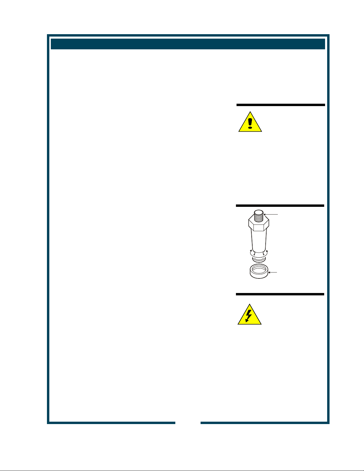
3. Remove the shield cap (large vent) on top of the sight glass.
NOTE: It is not necessary to remove the sight glass unless it
is broken and replacement is required.
4. Run the sight glass brush up and down through the sight
glass at least 10 times.
5. Reinstall and tighten the shield cap.
6. Drain sanitizer solution from satellite into the bucket.
7. Disassemble faucet. Brush clean with sanitizer solution.
Reassemble faucet.
8. Install satellite on brewer.
9. Rinse satellites: With an empty brew chamber in place, press
the BREW key and run 1 full cycle into each satellite.
10. Drain water from satellites.
Procedure is complete
CAUTION:
Burn Hazard
Brewing and serving
temperatures of coffee are
extremely hot.
Hot coffee will cause
serious skin burns.
WARNING:
Electric
Shock
Hazard
DO NOT immerse or
submerge satellites. Fluid
may saturate the insulation
and short-circuit the
receptacle connectors.
Electric shock may cause
injury and property
damage.
IMPORTANT:
DO NOT use steel wool, sharp
objects, or caustic, abrasive or
chlorinated cleansers to clean
the satellites.
672 74345 Owners Manual Dual Satellite 9520/9521
11
Page 14

Fig. 7 Function Keys
NOTE:
Time is held in memory and is
battery-backed. Clock change
should only be necessary for
daylight saving time, or if the
brewer is moved to another
time zone.
For advanced programming
features and instructions, refer
to PROGRAMMING MANUAL,
p/n 74346.
This brewer can be
programmed with a personal
computer.
Please contact your Bloomfield
Representative for details
NEW MENU SETTINGS
Menu Program:
Press POWER key to enter OFF mode.
Press and hold 3rd & 6th keys for 3 seconds
Advance thru menus by pressing the 1st key
Advance thru items by pressing the 3rd key
To exit, press 2nd key
Clock Settings:
Press POWER key to enter ON mode
Press 3rd & 4th keys at the same time
Check Tank Temperature:
Press POWER key to enter ON mode
Press 3rd & 6th keys at the same time
Page 15

PROGRAMMING INSTRUCTIONS (continued)
FEATURES
1. Energizing the Brewer: Turn the brewer on by pressing the
POWER key. The brewer will start to fill the tank with the
message on the screen “filling…”. With the proper water
supply the tank should be filled in about 2½ minutes. Once
PRECISE BREWING
TEMPERATURE™:
The brew cycle will not start
until the water in the tank is at
the proper temperatur e.
If START BREW key is pressed
and held for 3 seconds during
“Brew Wait” the brew will
proceed immediately.
Note: the following safety
features prevent multiple
unattended brews:
When the BREW LED is on or
flashing, repeated pressing of
the START BREW switch will be
ignored, (there will be a beep
each time it is pressed).
A Brew will only be activated or
put in Brew Wait when the
BREW LED is off.
Only one brew can be stored in
“Brew Wait” at a time.
13
Page 16

PROGRAMMING (continued)
ON/OFF – Normal Operation
(Non Automatic Timer):
To turn the brewer OFF, press
the POWER key: 2 beeps will be
heard and the brewer will be
turned OFF, indicated by all
lights being off.
To turn the brewer ON, press
the POWER key: 2 beeps will
sound, all lights will flash once,
then the POWER LED will glow.
NOTE: The HEAT LED will glow
if the water temperature is too
low when the brewer is turned .
5. View Water Temperature in Tank: To view the water
temperature on the screen, the brewer must be ON, and not
brewing or in the filling mode. Press and hold the 4th key,
and depress the 6th key. The actual water temperature will
be displayed for 3 seconds.
6. ON/OFF – Automatic Timer Feature:
The factory programmed Satellite Brewer has the automatic
timer turned off. To set the automatic timer, refer to “Time
Functions” Menu. If the Automatic Timer feature is
programmed off, the brewer can be turned on and off by
pressing the POWER key, as noted at left.
When the Automatic Timer feature is programmed ON the
Brewer will turn on and off automatically, at a programmed
time, Monday to Friday; with a separate on and off
programmed time schedule for Saturday and Sunday.
Temporarily Overriding the Automatic On/Off function:
While in the automatic timed OFF mode, the brewer can be
started by depressing the POWER key. The brewer will
remain on until the automatic programmed OFF time, when it
will turn off and resume normal automatic timed functioning.
Similarly, if turned OFF during the automatic timed ON mode
the brewer will remain OFF until the next programmed ON
time, when it will turn on and resume normal automatic timed
functioning.
14
Page 17

PROGRAMMING (continued)
7. Automatic Start-Up in Previous Mode:
If the Satellite Brewer automatic timer is OFF (the factory
setting) and power is disconnected, the brewer will start up
when power is restored, in the mode it had been in prior to
the power disconnection. If the Satellite Brewer has the
timer setting ON and power is disconnected, the brewer will
start up in the mode that it should be in at the time the power
is restored.
8. Brew Volume:
The Brewer can have up to 3 different brew volumes on each
side. When a volume other than the standard, or first brew
volume, is selected, the Brewer will complete that volume
and then automatically reset to the standard, or first brew
volume.
To view, press the individual volume key. The brew volume
will be displayed on the screen for 3 seconds. If there is
no brew volume for a specific key, the screen will read “no
volume prog”, (i.e. no volume programmed).
9. Clock
Time – Battery Backup. The Satellite Brewer has a battery
backup system which will maintain the proper time during
power failures, or when the brewer is unplugged (even for
very prolonged periods of time). Normally there will not be a
need to set the time except for Daylight Saving Time
changes, or moving the brewer to different time zones.
10. Changing Day and Time: To change time, in the OFF
mode, press the 2nd key twice followed by the 1st key twice
to access the time change mode. In the time change mode
he screen will read “Day:” followed by the current day
setting. Use the 6th key to advance the day, or the 5th key
to reverse.
When day has been properly set, press the 3rd key. The
screen will now read “Time:” with the set time on the screen,
the hour and am or pm flashing. Use the 6th key to advance
the hour, or the 5th key to reverse, making sure that the am
or pm is correct.
When the hour and am/pm is correctly set, press the 3rd key,
and the screen will read “Time:” with the set time on the
screen, minutes flashing. As previously, use the 5th or 6th
keys to adjust the minutes, and press the 3rd key when
complete. The Brewer will return to the off mode. (Changing
672 74345 Owners Manual Dual Satellite 9520/9521
time can also be done in the regular programming mode.)
Brew Volume
The 1st key is the Standard
Brew Volume.
When a brew volume other
than standard brew volume is
selected, the Brewer will
complete that brew then return
to the standard brew volume
automatically.
15
Page 18

PROGRAMMING (continued)
The factory programming has
the After Hours™ mode turned
OFF.
While in the After Hours mode,
the POWER LED will flash
continuously.
Keypadlock™ deters unauthorized
operation of the brewer. This
feature is OFF in the standard
factory settings.
12. After Hours™: The After Hours™ can be programmed to
come on from 1 to 6 hours after the last brew. When the
Brewer goes into the After Hours™ mode, the water in the
tank will be allowed to drop from the normal brewing
temperature and will reheat less frequently – this feature
saves energy and extend component life. When a START
BREW key is pressed the Brewer automatically reverts back
to normal operation, heating the water to the Precise
Temperature for Brewing™ (PTB™), before starting the
brew. (The POWER LED will be on continuously and the
BREW LED will flash until the correct water temperature is
reached.)
13. Pulse or Pre-Infusion Volume Options: If a particular brew
volume has utilized the pulse or pre-infusion option, that
volume will be displayed with an asterisk (*) after the volume.
As an example “Volume#2*” would indicate that the second
programmed brew volume has utilized the pulse or
pre-infusion program options.
14. Keypadlock™: If the Keypadlock™ feature is activated,
there will be no response by the brewer when the keys are
pressed (except for the beep after a key is pressed).
To temporarily “unlock” the keypad, press and hold the 2nd
key for 6 seconds. A beep will sound, indicating the keypad
is temporarily “unlocked”, — a brew can be initiated, etc.
The keypad will remain unlocked until the brew is completed,
then automatically return to keypadlock™ mode. If a brew is
not initiated 60 seconds after “unlocking”, the system will time
out and return to the “locked” position.
15. View Filter Statistics: To view filter statistics, from the OFF
mode, press and hold the 6th key, and touch the 3rd key to
viewTotal Water Volume (TotalVol.) Touch the 3rd key again
to view the filter life (FltrLife:). The percentage of the filter
that has been used will be displayed.
672 74345 Owners Manual Dual Satellite 9520/9521
16
Page 19

TROUBLESHOOTING SUGGESTIONS
DESCRIPTION OF PROBLEM POSSIBLE CAUSE SUGGESTED REMEDY
No lights or heat Unit not plugged in or circuit
Restore electric power
breaker tripped
Power switch OFF Turn power switch ON
No heat Hi-limit safety tripped Allow brewer to cool, verify water
level, reset hi-limit
Brewer overflows Water level probe corroded Clean water level probe
Poor ground connection Verify ground connection
Dirt in inlet valve or valve
Replace inlet valve
damaged
Brew valve damaged Replace brew valve
Brew chamber overflows Too many paper filters or wrong
filter used.
Chamber discharge hole
Use one genuine Bloomfield
paper filter per brew
Clean brew chamber
plugged
Improper programming Correct programming
Heats slow Connected to wrong voltage Verify supply voltage
Scale build-up on heating
De-lime hot water tank
elements
Damaged heating elem ent Replace element
Slow to fill Insufficient water pressure Brewer must be operated on a
dedicated water line. Other
equipment on line may be
robbing water volume.
Plugged water line strainer Clean strainer
Satellite does not heat Not properly seated Seat satellite in receptacle
Fuse blown Correct problem, replace fuse
Damaged satellite receptacle or
wiring
Determine/repair damage to
satellite
Damaged brewer recepta cle Repair/replace receptacle
Satellite shorts out Wet insulation Disassemble satellite, allow
to dry completely before
reassembly
Poor coffee quality Improper programming Correct programming
672 74345 Owners Manual Dual Satellite 9520/9521
Also:
Keep brewer and servers clean.
Install a taste and odor filter in water supply, and replace
cartridges regularly.
Use a quality coffee with a consistent roast. Use proper grind and
amount of coffee per brew.
17
Page 20

SERVICING INSTRUCTIONS
CAUTION -
CHEMICAL BURN
HAZARD
Deliming chemicals are caustic.
Wear appropriate pr ote ctive
gloves and goggles during this
procedure.
Never siphon deliming
chemicals or solutions by
mouth.
This operation should only be
performed by qualified and experienced service personnel.
IMPORTANT: DO NOT spill,
splash or pour water or deliming
solution into or over any internal
component other than the inside
of the water tank.
IMPORTANT: DO NOT allow
any internal components to
come into contact with t he
deliming solution. Take care to
keep all internal components
dry.
NOTE: Repeat steps 4 and 7
as required to remove all buildup.
PROCEDURE: Delime the Water Tank
PRECAUTIONS: Disconnect brewer from electric power.
Allow brewer to cool.
FREQUENCY: As required (Brewer slow to heat)
TOOLS: Deliming Solution
Protective Gloves, Goggles & Apron
Mild Detergent, Clean Soft Cloth or Sponge
Bristle Brush, Bottle Brush
Large Sink (or other appropriate work area)
1. Disconnect brewer from the electrical supply.
2. Remove the brewer top panel, then remove the tank lid
assembly. Do not disconnect the tank assembly at this
time.
3. Siphon all water from the hot water tank.
4. Mix 10 gallons of deliming solution according to the
manufacturer’s directions. Carefully pour the deliming
solution into the water tank. Lower the lid assembly back
onto the tank. Allow to sit for 30 minutes, or as directed by
the chemical manufacturer.
5. At end of soaking period, reconnect brewer to electrical
power. Install the brew chamb er without f ilte r pa per or
grounds. Place an empty satellite under the brew
chamber. Force a 1-1/2 gallon brew:
a. Press the 1-1/2 gallon key
b. Press the brew key, then press and hold the brew key
until a brew is initiated.
Empty the satellite and repeat for the other side.
6. Disconnect brewer from electrical power and allow to cool.
7. Remove lid assembly from tank.
a. Using a stiff bristle brush, scrub internal components to
remove lime and calcium build-up.
b. Thoroughly rinse internal components of lid assembly
with clear water.
c. Store lid assembly in a safe location.
8. Using a stiff bristle brush, scrub exposed portions of the
heating element and the inside surfaces of the tank to
remove lime and calcium build-up.
9. Siphon all solution from the tank.
672 74345 Owners Manual Dual Satellite 9520/9521
18
Page 21

SERVICING INSTRUCTIONS (continued)
10. Reinstall tank lid assembly into hot water tank. Make sure
the lid gasket is properly in place, then reinstall the hold down clamps.
11. Remove spray disks and gaskets. Rinse both brew heads
with clean water. Using a stiff brush, scrub spray disk to
remove any lime or calcium build-up. Reinstall gaskets
and spray disks.
13. Reconnect brewer to electrical supply .
14. Install the brew chamber without filter paper or grounds.
15. Place an empty satellite under the brew chamber. Run at
least five 1-1/2 gallon brew cycles and discard all water
generated at the end of each cycle.
Repeat for the other side.
16. Rinse satellite with clean water. Reinstall one empty
satellite under each brew chamber.
Brewer is ready to use.
NOTE: Normally, silicone
hoses do not need to be
delimed. Should deliming
hoses become necessary,
Bloomfield recommends
replacing the hoses.
672 74345 Owners Manual Dual Satellite 9520/9521
19
Page 22

EXPLODED VIEW CABINET AND EXTERIOR COMPONENTS
20
Page 23

PARTS LIST - CABINET AND EXTERIOR COMPONENTS
672 74345 Owners Manual Dual Satellite 9520/9521
21
Page 24

EXPLODED VIEW INTERIOR COMPONENTS
22
Page 25

PARTS LIST - INTERIOR COMPONENTS
23
Page 26

EXPLODED VIEW WIRING DIAGRAM
24
672 74345 Owners Manual Dual Satellite 9520/9521
Page 27

SATELLITE EXPLODED VIEW, PARTS LIST & WIRING DIAGRAM
ITEM PA RT NO. DESCRIPTION QTY
1 83863 TANK LID ASSY 1
2 83099 HANDLE, SATELLITE TOP 2
5 SCREW, 8 -32x3/8“ BL K OXIDE 8
6 STIFFENER BRACKET, LEFT 1
7 83558 T OPCOVER, SAT ELLITE 1
8 FRAME, DECAF (PART OF #9) 1
9 83092 DOOR, DECAF 1
10 83112 FAUCET w/SIGHT GLASS, 10“ 1
8600-17 SHIELD CAP
10.01 1
8700-25 J CAP WASHER
10.02 1
10.03 8705-11 C SIGHT GLASS 1
10.04 8600-20 SHIELD ASSY 1
10.05 870 5-11 B BASE WASHER 1
10.06 8705-1 16 SHIELD BASE 1
10.08 8600-26 C-RING 1
10.09 8600-27 WING NUT 1
10.10 8700-25 L SEAT C UP 1
10.20 8705-11 D SHANK ASSY
12 84326 HANDLE GUARD, FAUCET 1
13 83172 RECEPTICAL, WIRED ASSY 1
14 83114 EL EMENT, HEATER, 45W 1
15 83117 TANK INSULATION 1
16 83057 BAS E, POLYPROPYLENE 1
17 PLATE STIFFENER 1
18 WELDEMENT, SATELLITE BODY 1
19 TANK SUB ASSY w/FITTINGS 1
20 T AP E, GLASS CLOTH .33
21 THREADLOCK, RED A/R
22 8705-26 SEAL, DRAIN FITTING 2
23 TAPE, TE FLO N 1.74
24 LABEL, SATELLITE 1
25 SCREW, PAN PHL 8-32x1/2“ 4
26 STIFFENER BRACKET, RIGHT 1
27 SCREW, T RS PHL SS 10-32x3/8“ 4
28 8705-33 O-RING 1
30 WASHER #1 0 4
33 8942-92 NUT, KEP SS 8-32 3
34 83132 LABEL, CAUTION “DO NOT IMMERSE...” 1
25
Page 28

Bloomfield Industries, Inc.
Division of Carrier Commercial Refrigeration
In US and Canada
Telephone: 775-689-5700
Fax:
Fax:
888-492-2783
800-356-5142 ()
for orders only
website: www.wellsbloomfield.com
 Loading...