

Page 1
WELLS BLOOMFIELD, LLC
2 ERIK CIRCLE, P. O. Box 280 Verdi, NV 89439
telephone: 775-689-5703
fax: 775-689-5976
www.wellsbloomfield.com
OWNERS MANUAL
HYDRO-SURGE
PW-106
INSTALLATION
USE & CARE
591
Model
Includes
This manual is considered to be part of the appliance and is to be given to the OWNER or
MANAGER of the restaurant, or to the person responsible for TRAINING OPERATORS of
this appliance. Additional manuals are available from your WELLS DEALER.
THIS MANUAL MUST BE READ AND UNDERSTOOD BY ALL PERSONS U S ING OR
INSTALLING THIS APPLIANCE. Contact your WELLS DEALER if you have any
questions concerning installation, operation or maintenance of this equipment.
p/n 305486 Rev. B ECN-13380 M591 071101 cps
IMPORTANT: DO NOT DISCARD THIS MANUAL
PRINTED IN UNITED STATES OF AMERICA
Page 2

LIMITED WARRANTY STATEMENT
Unless otherwise specified, all commercial cooking
equipment manufactured by WELLS BLOOMFIELD, LLC is
warranted against defects in materials and workmanship for
a period of one year from the date of original installation or
18 months from the date of shipment from our factory,
whichever comes first, and is for the benefit of the original
purchaser only.
THIS WARRANTY IS THE COMPLETE AND ONLY
WARRANTY, EXPRESSED OR IMPLIED IN LAW OR IN
FACT, INCLUDING BUT NOT LIMITED TO, WARRANTIES
OF MERCHANTABILITY OR FITNESS FOR ANY
PARTICULAR PURPOSE, AND/OR FOR DIRECT,
INDIRECT OR CONSEQUENTIAL DAMAGES IN
CONNECTION WITH WELLS BLOOMFIELD PRODUCTS.
This warranty is void if it is determined that, upon inspection
by an authorized service agency, the equipment has been
modified, misused, misapplied, improperly installed, or
damaged in transit or by fire, flood or act of God. It also
does not apply if the serial nameplate has been removed, or
if service is performed by unauthorized personnel. The
prices charged by Wells Bloomfield for its products are
based upon the limitations in this warranty. Seller’s
obligation under this warranty is limited to the repair of
defects without charge by a Wells Bloomfield factory
authorized service agency or one of its sub-service
agencies. This service will be provided on customer’s
premises for non-portable models. Portable models (a
device with a cord and plug) must be taken or shipped to
the closest authorized service agency, transportation
charges prepaid, for service. In addition to restrictions
contained in this warranty, specific limitations are shown in
the Service Policy and Procedure Guide. Wells Bloomfield
authorized service agencies are located in principal cities.
This warranty is valid in the United States and Canada and
void elsewhere. Please consult your classified telephone
directory, your foodservice equipment dealer or contact:
Service Department, Wells Bloomfield, LLC
P.O. Box 280, Verdi, Nevada 89439
phone (775) 689-5707 or fax (775) 689-5976
for information and other details concerning warranty.
SERVICE POLICY AND PROCEDURE GUIDE and ADDITIONAL WARRANTY EXCLUSIONS
1. Resetting of safety thermostats, circuit breakers, over
load protectors, and/or fuse replacements are not
covered by this warranty unless warranted conditions
are the cause.
2. All problems due to operation at voltages or phase
other than specified on equipment nameplates are
not covered by this warranty.
Conversion to correct voltage and/or phase must be
the customer’s responsibility.
3. All problems due to electrical connections not made
in accordance with electrical code requirements
and wiring diagrams supplied with the equipment are
not covered by this warranty.
4. Replacement of items subject to normal wear, to
include such items as knobs, light bulbs; and, normal
maintenance functions including adjustments of
thermostats, adjustment of micro switches and
replacement of fuses and indicating lights are not
covered by warranty.
5. Damage to electrical cords and/or plug due to exposure
to excessive heat are not covered by this warranty.
6. Full use, care, and maintenance instructions supplied
with each machine. Noted maintenance and
preventative maintenance items, such as servicing and
cleaning schedules, are customer responsibility. Those
miscellaneous adjustments noted are customer
responsibility. Proper attention to preventative
maintenance and scheduled maintenance procedures
will prolong the life of the appliance.
7. Travel mileage is limited to sixty (60) miles from an
Authorized Service Agency or one of its sub-service
agencies.
8. All labor shall be performed during regular working
hours. Overtime premium will be charged to the buyer.
9. All genuine Wells replacement parts are warranted for
ninety (90) days from date of purchase on nonwarranty equipment. This parts warranty is limited only
to replacement of the defective part(s). Any use of
non-genuine Wells parts completely voids any
warranty.
10. Installation, labor, and job check-outs are not
considered warranty and are thus not covered by this
warranty.
11. Charges incurred by delays, waiting time or operating
restrictions that hinder the service technician’s ability to
perform service are not covered by warranty. This
includes institutional and correctional facilities.
591 p/n 305486 OwM PW-6 Power-Surge
SHIPPING DAMAGE CLAIM PROCEDURE
NOTE: For your protection, please note that equipment in
this shipment was carefully inspected and packaged by
skilled personnel before leaving the factory. Upon
acceptance of this shipment, the transportation company
assumes full responsibility for its safe delivery.
IF SHIPMENT ARRIVES DAMAGED:
1. VISIBLE LOSS OR DAMAGE: Be certain that any
visible loss or damage is noted on the freight bill or
express receipt, and that the note of loss or damage is
signed by the delivery person.
2. FILE CLAIM FOR DAMAGE IMMEDIATELY:
Regardless of the extent of the damage.
3. CONCEALED LOSS OR DAMAGE: if damage is
unnoticed until the merchandise is unpacked, notify the
transportation company or carrier immediately, and file
“CONCEALED DAMAGE” claim with them. This
should be done within fifteen (15) days from the date
the delivery was made to you. Be sure to retain the
container for inspection.
Wells Bloomfield cannot assume liability for damage or loss
incurred in transit. We will, however, at your request, supply
you with the necessary documents to support your claim.
xi
Page 3

TABLE OF CONTENTS
WARRANTY xi
SPECIFICATIONS 1
FEATURES & OPERATING CONTROLS 2
PRECAUTIONS & GENERAL INFORMATION 3
AGENCY LISTING INFORMATION 3
INSTALLATION 4
OPERATION 5
CLEANING INSTRUCTIONS 6
TROUBLESHOOTING SUGGESTIONS 7
EXPLODED VIEW 8
WIRING DIAGRAM 8
PARTS & SERVICE 9
CUSTOMER SERVICE DATA 9
INTRODUCTION
Thank You for purchasing this Wells Bloomfield appliance.
Proper installation, professional operation and consistent maintenance of this appliance will ensure that
it gives you the very best performance and a long, economical service life.
This manual contains the information needed to properly install this appliance, and to use and care for
the appliance in a manner which will ensure its optimum performance.
SPECIFICATIONS
MODEL VOLTS
1ø
120 VAC 60 Hz 1/3 6.0 NEMA 5-15P
PW-106
PW-106 is shipped wired for 120VAC, 60Hz.
* 120VAC 60Hz unit may be converted to 240VAC 60Hz by reconfiguring motor wiring and replacing
power supply cord. Note: This conversion is not UL Listed.
591 p/n 305486 OwM PW-6 Power-Surge
** Export unit only
230/240 VAC * 60Hz 1/3 3.0 not provided
220 VAC ** 50Hz 1/3 3.0 not provided
CYCLES MOTOR HP AMPS POWER SUPPLY
CORD
4' LONG
1
Page 4
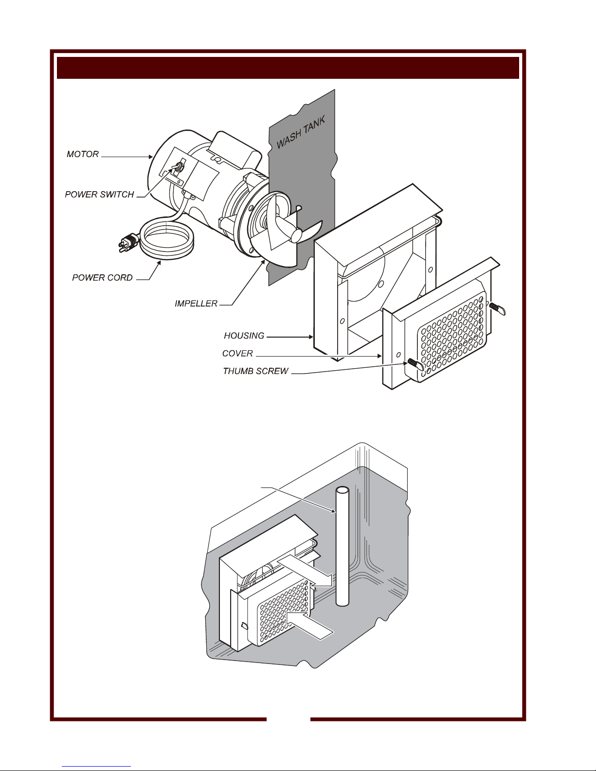
FEATURES & OPERATING CONTROLS (continued)
Fig. 1 Features and Operating Controls
Note: unit is shown partially disassembled for clarity
OVERFLOW
(by others)
WATER LEVEL
DISCHARGE
SUCTION
Fig. 2 PW-106 Operation
591 p/n 305486 OwM PW-6 Power-Surge
2
Page 5

PRECAUTIONS AND GENERAL INFORMATION
This appliance is intended for use in commercial establishments
only.
This appliance is intended
other use is
agents.
Operators of this appliance must be familiar with the appliance use,
limitations and associated restrictions. Operating instructions must be
read and understood by all persons using or installing this appliance.
Cleanliness of this appliance is essential to good sanitation. Read and
follow all included cleaning instructions and schedules to ensure the
safety of the food product.
Disconnect this appliance from electrical power before performing any
maintenance or servicing.
Exposed surfaces of this appliance can be hot to the touch and may
cause burns.
Impeller blades are sharp:
DO NOT operate the unit unless the cover is properly installed.
Use care when cleaning the impeller.
The technical content of this manual, including any wiring diagrams,
schematics, parts breakdown illustrations and/or adjustment
procedures, is intended for use by qualified technical personnel.
Any procedure which requires the use of tools must be performed by a
qualified technician.
This manual is considered to be a permanent part of the appliance.
This manual and all supplied instructions, diagrams, schematics, parts
breakdown illustrations, notices and labels must remain with the
appliance if it is sold or moved to another location.
This appliance is made in the USA. Unless otherwise noted, this
appliance has American sizes on all hardware.
recommended or authorized by the manufacturer or its
to assist in cleaning cooking utensils. No
WARNING:
ELECTRIC
All servicing requiring
access to non-insulated electrical components must be
performed by a factory authorized technician.
DO NOT open any access
panel which requires the use
of tools. Failure to
follow this warning can
result in severe electrical
shock.
SHOCK HAZARD
CAUTION:
RISK OF
DAMAGE
DO NOT connect or
energize this appliance
until all installation
instructions are read and
followed. Damage to the
appliance will result if
these instructions are not
followed.
CAUTION:
CUT HAZARD
Impeller blades are sharp.
DO NOT operate the unit
unless the cover is properly
installed.
Use care when cleaning the
impeller.
This appliance is
only.
591 p/n 305486 OwM PW-6 Power-Surge
U Listed under UL File E27255 for 120VAC 60Hz
AGENCY LISTING INFORMATION
E27255
3
Page 6

INSTALLATION
NOTE: DO NOT discard
the carton or other packing
materials until you have
inspected the appliance for
hidden damage and tested it
for proper operation.
Refer to SHIPPING DAMAGE
CLAIM PROCEDURE on the
inside front cover of this
manual.
WARNING:
RISK OF INJURY
Installation procedures must
be performed by a qualified
technician with full knowledge
of all applicable electrical and
plumbing codes. Failure can
result in personal injury and
property damage.
IMPORTANT:
This appliance must be
plugged into a properly
grounded receptacle.
120VAC units require a
NEMA 5-15R receptacle
240VAC units require a
NEMA 6-15R receptacle.
Contact a licensed electrician
to install and connect a proper
receptacle.
IMPORTANT:
Damage due to being
connected to the wrong
voltage or phase is NOT
covered by warranty.
IMPORTANT:
DO NOT run Hydro-Surge dry.
Operating the unit dry will
damage the seals and allow it
to leak.
UNPACKING & INSPECTION
Carefully remove the appliance from the carton. Remove all
protective plastic film, packing materials and accessories from the
Appliance before connecting electrical power or otherwise performing
any installation procedure.
Carefully read all instructions in this manual and the Installation
Instruction Sheet packed with the appliance before starting any
installation.
Read and understand all labels and diagrams attached to the
appliance.
Carefully account for all components and accessories before
discarding packing materials. Store all accessories in a convenient
place for later use.
COMPONENTS
1 ea MOTOR ASSEMBLY
1 ea GASKET, TANK TO MOUNTING PLATE
1 ea PUMP HOUSING ASSEMBLY
1 ea COVER
HARDWARE and LITERATURE
INSTALLATION
IMPORTANT: Layout, installation and any conversion to be performed
by a qualified service technician only.
Layout mounting holes per Installation Instruction. After completing
cutout operations, carefully deburr all holes.
NOTE: Hydro-Surge unit is designed to mount on the LEFT side of the
wash tank. If mounting to the right side:
a. Rotate motor until switch is accessible from the front.
b. Remove and reinstall motor connector box cover so that switch
markings are right-side-up.
NOTE: Hydro-Surge part no. 20621 is shipped from the factory wired
for 120 volts AC, 60 Hz. If unit is to be used for 240 volts:
a. Purchase part no. 50434 240 VAC power cord.
b. Reconfigure motor wiring connections per motor label as
required for 240 VAC.
c. Install 240VAC power cord. Be sure to tighten strain relief.
IMPORTANT: 240V conversion is not UL Listed.
Apply a thin bead of food-grade silicone sealant to one face of the
gasket, then apply gasket to the mounting plate of the motor assembly.
Apply a thin bead of food-grade silicone sealant to the exposed face of
the gasket, then assemble the motor and pump housing to the wash
tank. Test impeller to be sure it rotates without contacting the pump
housing. Adjust as necessary. Bolts need be only tight enough to
prevent leaks. Over-tightening is not necessary
Install the cover. Thumbscrews need only be finger-tight.
Fill wash tank. Plug unit into a appropriate receptacle and test for
proper operation.
591 p/n 305486 OwM PW-6 Power-Surge
4
Page 7

OPERATION
OPERATION
Place items to be washed in the wash tank
Fill wash tank to a depth of 10", or up to the level of the overflow, with
hot tap water.
NOTE: If using a detergent, a low-foaming detergent is recommended.
Turn the power switch ON. Allow the unit to operate as long as
necessary to remove food particles.
Hydro-Surge cleans by the scrubbing action of fast-moving water. If
cleaning a large number of items, rotate the items frequently so that
each spends some time nearest the Hydro-Surge discharge.
SUGGESTIONS
Inspect each item for thorough cleaning. Additional hand cleaning may
be necessary to insure complete food removal.
If detergent is used, items must be rinsed with clean water prior to use.
CAUTION:
CUT HAZARD
Impeller blades are sharp.
DO NOT operate the unit
unless the cover is properly
installed.
IMPORTANT:
DO NOT run Hydro-Surge
dry. Operating the unit dry
will damage the seals and
allow it to leak.
591 p/n 305486 OwM PW-6 Power-Surge
5
Page 8

CLEANING INSTRUCTIONS
CAUTION:
CUT HAZARD
Turn power switch OFF and
disconnect unit from electric
power before cleaning.
CAUTION:
CUT HAZARD
Impeller blades are sharp.
DO NOT operate the unit
unless the cover is properly
installed.
Use care when cleaning the
impeller.
PREPARATION Turn power switch OFF
Unplug from electrical power
Drain wash tank
FREQUENCY Daily, or as needed
TOOLS Bottle Brush, Soft Bristle Brush
Soft Cloth or Sponge
CLEANING
1. Turn power switch OFF and unplug unit. Drain wash tank.
2. Remove cover. Store thumb screws for later use.
3. Using brushes, clean in, around and behind impeller. Remove any
mop strings or other fibers from impeller shaft.
4. Clean all accessible area s of the pump housing.
5. Check impeller for free rotation. Reassemble cover.
6. Wipe motor, power switch and power cord with a soft cloth
dampened with clean water.
7. Plug unit into receptacle.
Procedure is complete.
591 p/n 305486 OwM PW-6 Power-Surge
6
Page 9

TROUBLESHOOTING SUGGESTIONS
SYMPTOM PROBABLE CAUSE SUGGESTED REMEDY
No power to unit Unit unplugged or circuit breaker
tripped
Plug unit into appropriate
receptacle
Reset circuit breaker
Unit will not run Power switch off Turn switch ON
Internal overload tripped Allow motor to cool
Damaged power cord Replace power cord
Damaged power switch Replace switch
Damaged motor Replace motor
Trips internal overload Impeller jammed Clean impeller. Be sure impeller
is not binding on pump housing.
Impeller damaged Replace impeller
Motor improperly wired Motor must be wired per the
attached label for the electrical
supply voltage.
Mounting plate-to-motor screws
Tighten mounting plate screws
loose
Damaged motor Replace motor
Leaks at pump shaft Damaged pump seal Replace seal
Leaks at mounting Mount bolts loose Tighten mounting blots
591 p/n 305486 OwM PW-6 Power-Surge
Gasket damaged Replace gasket.
7
Page 10

EXPLODED VIEW
WIRING DIAGRAM
120 VAC 60 Hz
Standard Configuration
240 VAC 60 Hz
Conversion
NOTE:
This conversion is not
UL Listed.
591 p/n 305486 OwM PW-6 Power-Surge
8
Page 11

DESCRIPTION PART NO.
The following parts are available through your Authorized Wells
Service Agency:
SERVICE & REPAIR
IMPELLER 55898
GASKET, TANK TO MTG PLATE 55899
SEAL, PUMP 55902
PUMP HOUSING 55906
THUMB SCREW 55907
COVER, PUMP 55911
VOLTAGE CONVERSION
IMPORTANT:
This appliance is
CORD SET 240 VAC 60 Hz 50434
MOTOR 220 VAC 50 Hz 60263
U Listed for 120 VAC 60 Hz only.
PARTS & SERVICE
IMPORTANT: Use only
factory authorized service
parts and replacement
filters.
For factory authorized
service, or to order factory
authorized replacement parts,
contact your Wells authorized
service agency, or call:
Wells Bloomfield, LLC
2 Erik Circle
P. O. Box 280
Verdi, NV 89439
Service Parts Dept.
phone: (775) 689-5707
fax: (775) 689-5976
Service Parts Department can
supply you with the name and
telephone number of the
WELLS AUTHORIZED
SERVICE AGENCY
nearest you.
RESTAURANT _____________________________ LOCATION _____________
INSTALLATION DATE ________________________ TECHNICIAN ___________
SERVICE COMPANY ________________________________________________
ADDRESS ___________________________ STATE ______ ZIP__________
TELEPHONE NUMBER (_____)_____-_________
EQUIPMENT MODEL NO. _______________
591 p/n 305486 OwM PW-6 Power-Surge
EQUIPMENT SERIAL NO. _______________
VOLTAGE: (check one) 120 220 240
CUSTOMER SERVICE DATA
please have this information available if calling for service
9
Page 12

Genuine Parts
Protect - YOU - All - Ways
SERVICE TRAINING - QUALITY SERVICE
CUSTOMER SATISFACTION
Commercial Food Equipment Service Association
Wells Bloomfield proudly supports CFESA
Commercial Food Equipment Service Association
SERVICE TRAINING - QUALITY SERVICE
CUSTOMER SATISFACTION
WELLS BLOOMFIELD, LLC
2 ERIK CIRCLE, P. O. Box 280 Verdi, NV 89439
telephone: 775-689-5703
fax: 775-689-5976
www.wellsbloomfield.com
PRINTED IN UNITED STATES OF AMERICA
 Loading...