

Bloomfield MOD-400, MOD-400D, MOD-400T, MOD-400TD, MOD-400TDM Installation Instructions Manual
Page 1
ELECTRICAL
VOLTS WATTSMODELS
MOD-400
MOD-400
MOD-400T
MOD-400T
ALL MODELS WITH A 'D' OR 'DM'
240
208
4800
4960
SUFFIX HAVE THE SAME ELECTRICAL
AMPS PER LINE 3 PHASE
11.2208 3600
13.0
14.5
17.8240 6600
11.2
13.0
14.5
17.8 11.3
AMPS
SINGLE
L3L2L1
PHASE
7.5
8.7
9.8
17.3
20.0
23.8
27.5
SPECIFICATIONS AS THE STANDARD
FIELD WIRING GAUGE
3 PHASE
12 AWB Cu
12 AWB Cu
12 AWB Cu
12 AWB Cu
TEMP.
1 PHASE
10 AWB Cu
10 AWB Cu
8 AWB Cu
8 AWB Cu
RATING
75°C
75°C
75°C
75°C
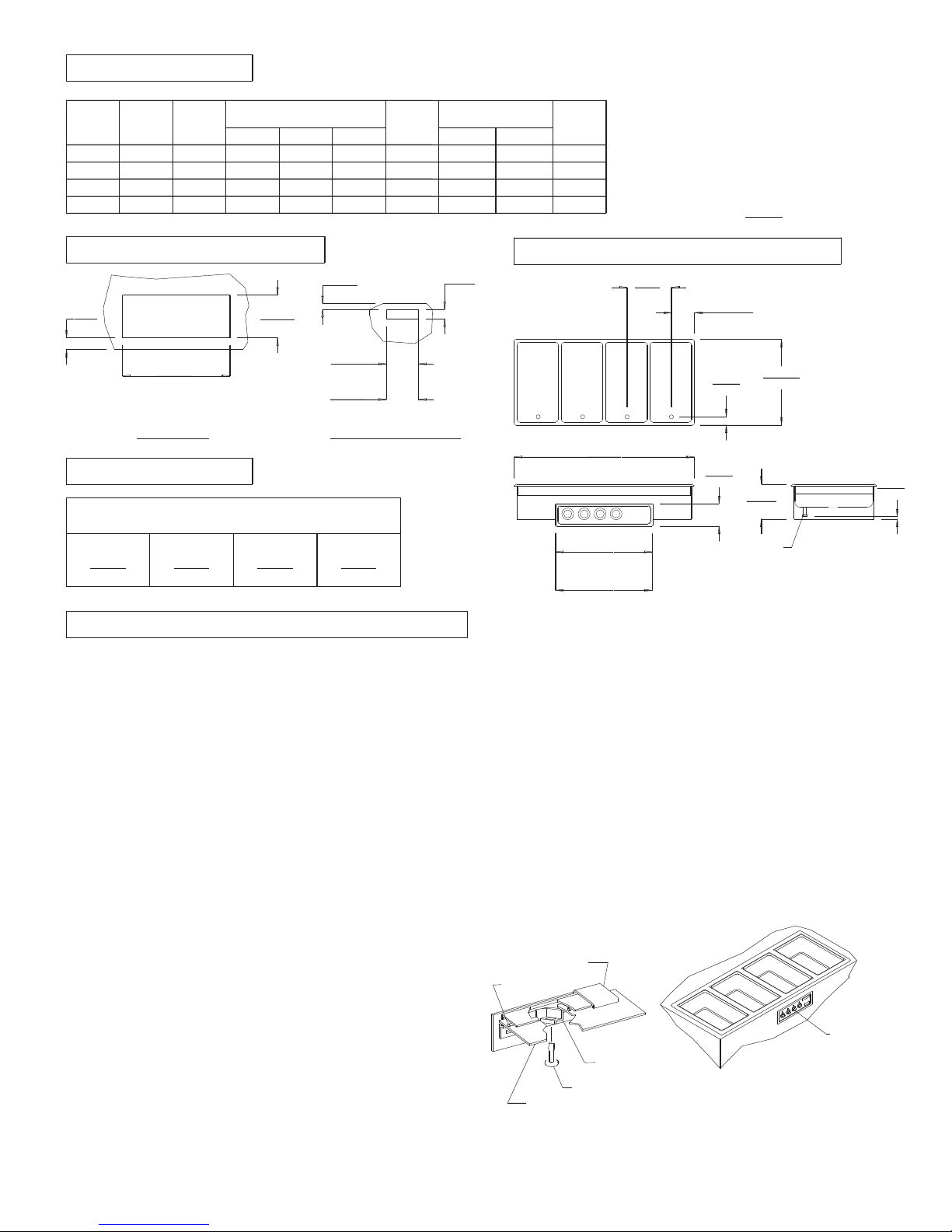
MOD-400 AND MOD-400T MODELS
INSTALLATION INSTRUCTIONS
BUILT-IN MODULAR WARMERS
MOD 400 SERIES (D, TD, TDM)
INCHES
(MM)
CUTOUT DETAILS
3 1/8
(79)
6
(152)
56 1/2
(1435)
22 1/2
(572)
'T' MODELS
16 7/8
(430)
33 7/8
(860)
FRONT PANEL CUTOUTTOP CUTOUT
CLEARANCES
MINIMUM CLEARANCE REQUIRED FROM
UNITS TO THE NEAREST SURFACE
BACK SIDE BOTTOM FRONT
1 1 6 3/4 6
(25) (25) (171) (152)
INSTALLATION INSTRUCTIONS
NOTE: MOD-400 UNITS ARE SHIPPED THREE PHASE AND
ARE FIELD CONVERTIBLE TO SINGLE PHASE. THE DRAIN
MANIFOLD WITH 1" INTERNAL NPT VALVE IS SUPPLIED
FOR DM AND TDM MODELS ONLY.
INSTALLER MUST MEET CONDITIONS OF ACCEPTABILITY
OUTLINED BELOW UPON INSTALLATION:
1. Required Installation Clearances:
Wooden and Metal Installation: DO NOT install closer than
6 inches to front wall, 1 inch to back and side walls, and
6 3/4 inches to a surface below the unit.
2. Unit shall be accessible for servicing from the bottom.
3. If storage is to be used underneath the unit, it is
recommended that a baffle be placed 8 1/2 inches below
the unit to avoid contact with elevated temperatures.
TO FABRICATE:
1. Layout "cutout" dimensions on countertop and front
apron.
2. Layout and fabricate control panel holes in counter
apron using the control box as a template.
3. Cut out holes.
4. Unit shall be accessible for servicing from the bottom.
TO INSTALL:
IMPORTANT - DO NOT disconnect "lead wires" from the
Master Control Panel when making installation.
1. Tilt and pass Control Panel and electrical box through
countertop cutout, then through apron cutout. Lower
modular section into countertop cutout and position.
RECOMMENDATION: Before final seating of modular section
to countertop, apply a bead of silicone adhesive/sealant
to underside of gray gasket material supplied on mounting
flange.
2. From underneath, insert screwdriver into "slots" in
Wellslok frame and twist "ears" outward (clockwise) as
required to secure flange tightly to countertop.
3. Mount Control Box to apron cutout as shown in drawing.
PRODUCT DIMENSIONS
5
(127)
57 1/2
(1461)
18
(457)
35
(889)
4. Mount Control Panel onto electrical box using screws
supplied.
TO PLUMB:
1. A drain manifold complete with valve is supplied on all
Model "DM" and "TDM" units. Location of valve handle is at the
discretion of the fabricator. Install and tighten pipe plug in
one end of the manifold.
2. Warmers with 'D" suffix are supplied with individual 1/2''
female N.P.T. drains.
3. Connect 1'' drain connection to suitable drain line.
TO WIRE:
1. Final connection is accomplished by bringing proper power
supply leads (see 'wiring requirements' label) through conduit
knockout to terminal block supplied within the Master Control
Panel. Check nameplates for voltage and phase.
2. Do not connect to a circuit operating at more than 150
volts to ground.
NOTE: INSTALLATION MUST MEET LOCAL PLUMBING AND
ELECTRICAL CODES.
WARMER FLANGE
GASKET
SCREWDRIVER
COUNTERTOP
WELLS/BLOOMFIELD * VERDI, NV
(356)
WELLSLOK
14
'T' MODELS
7 3/4
(197)
2 1/4
(57)
6 1/4
(159)
IMPORTANT:
MOUNT APPLIANCE SO THAT BOTH
THE CONTROL PANEL AND DRAIN
MANIFOLD ARE LOCATED TO THE
FRONT OF THE FIXTURE.
23 5/8
(600)
9 3/4
(248)
1/2 INCH
INTERNAL N.P.T.
'D' MODELS ONLY
37099-4 REV (-)
MASTER
CONTROL
PANEL
1 3/4
(44)
 Loading...