

Page 1
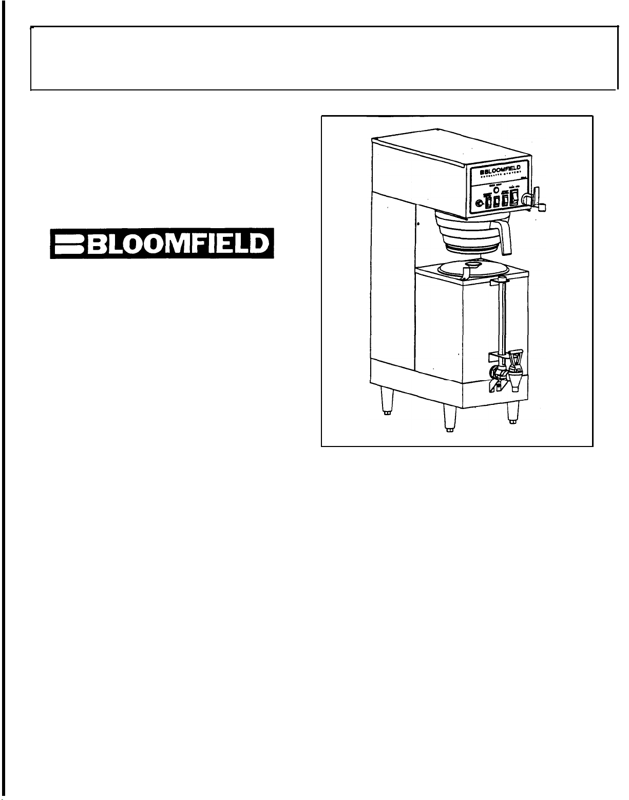
1/2, 1, AND 1 1/2 GALLON SATELLITE BREWER
BLOOMFIELD MODEL #9107A & 9107AW
BY
BLOOMFIELD INDUSTRIES
2 ERIK CIRCLE
P.O.BOX 280
VERDI, NV 89439
U.S.A.
FAX (800) 356-5142
PH (702) 345-0444
PRE INSTALLATION INSTRUCTION
PLUMBER‘S INSTALLATION INSTRUCTIONS
ELECTRICIAN’S INSTALLATION INSTRUCTIONS
INITIAL OPERATING INSTRUCTIONS
BREWING INSTRUCTIONS
TIMER ADJUSTMENT INSTRUCTIONS
BY-PASS ADJUSTMENT INSTRUCTIONS
EXPLODED VIEW
PARTS LIST
WIRING DIAGRAM 9107A
WIRING DIAGRAM 9107AW
72403 Rev (A)
TABLE OF
Printed in April, 1996
CONTENTS
PAGE 2
PAGE 2
PAGE 3
PAGE 3
PAGE 4
PAGE 4
PAGE 5
PAGE 8
PAGE 7
PAGE 8
PAGE 9
Page 2
INSTALLATION INSTRUCTlON
READ THIS COMPLETELY BEFORE STARTING THE INSTALLATION
WARNING: DO NOT plug In or energize this unit until installation instructions are read
and followed.
To enable the installer to make a quality installation and hold delay time to a minimum,
the following suggestions and tests should be done before the actual unit installation is
begun.
LEVELING THE UNIT
Set Coffee Brewer In operating location and level.
important that the unit be level when it is standing in its proper operation position
A spirit level should be place on the top plate of the unit, at the edge, as a guide
when making level adjustments. Level the unit from left to right and front to back by
turning the adjustable feet that support the unit.
For proper unit operation, It is very
PLUMBER’S INSTALLATION INSTRUCTION
NOTE:
Building Officials and Code Administrators international, inc (BOCA) and the Food Service
Sanitation Manual of the Food and Drug Administration. (FDA)
Flush water line before connecting to Brewer. Brewer should be connected to COLD
WATER line
NOTE:
3/8’ for more than 25 feet from the 112’ water supply line.
A water shut-off valve should be installed on the Incoming water Iine in a convenient
location.
Unit must be installed on a water line with a flowing pressure between 20 PSI and 90 PSI.
if water pressure does not fail into this range or varies greatly, a pressure regulator
should be installed in the water supply line.
To delay build-up of lime deposits in water tank, we recommend the use of a Water
Strainer.
This equipment must be installed to comply with the Basic Plumbing Code of the
Bloomfield recommends 1/4’ copper tubing for installation of less than 25 feet and
Page 3

ELECTRICIAN’S INSTALLATION lNSTRUCTlONS
WARNING Brewer must be properly grounded to prevent possible shock hazard.
DO NOT assume a plumbing line will provide such a ground.
Unit requires a dedicated power source capable of supplying: 115/208 Volt, AC.,
50/60 Hertz, (4) wire, 20 Amp Service.
The unit is shipped from the factory with a power cord and cap
NOTE: Make sure tank heater switch on front panel Is in OFF position. Bottom portion of
switch rocker should be pressed in.
element and void warranty.
-Failure to turn off the element’ will damage the
INITIAL OPERATING INSTRUCTIONS
NOTE: Operations should be performed by a qualified Installer.
Electrician’s and Plumber’s instructions should be followed carefully before
proceeding with Initial Operating instructions.
Be sure ail electrical and plumbing connections are tight.
Make sure Tank Heater Switch on Front Panel is still in OFF position.
Place empty Satellite under the Brewer.
Press Brew Start Switch to initiate brewing cycle. This will energize the
solenoid and will begin filling the tank.
only).
Press Brew Stop Switch when water begins to flow from spray disc.
Turn Tank Heater Switch to ON position.
Allow 30 minutes for initial water heat up.
temperature.
When tank water Is up to proper temperature, the green READY TO BREW light will
be ill.
NOTE: During the initial heat-up, some water may drip from spray disc. This is normal.
Brewer is ready for use.
(Approximately 3 Cycles for initial fill
Time will vary with incoming water
3
Page 4

BREWING INSTRUCTIONS
Place filter paper in Brew Chamber and add Coffee. Slide Brew basket into rails,
pushing it to full back stop location.
bypass to flow behind the filter.
Press Brew Switch to initiate brewing cycle.
Make sure drip-out is complete before removing Brew Chamber.
if for any reason there is a need to stop the brewing cycle before its completion,
press the “Brew Stop’ switch. This stops water flow to the Brew Chamber. The timing
cycle is also canceled and timer resets to start.
Make sure paper is properly located for
Check Volume.
below.
NOTE:
Inlet water is controled by .35 GPM flow control in solenoid.
To change the volume quantity, see ‘Timer Adjustment Instructions’
TIMER ADJUSTMENT INSTRUCTIONS
NOTE:
This Brewer was Pre-Adjusted at 1/2, 1, or 1 1/2 Gallons of Coffee.
Following to be done if it is necessary to fine tune the timer to match brewed
quantity.
All operating controls are accessible to Top Cover only.
1. Unplug power at source.
2. Remove the Top Cover by removing two (2) #8 Screws.
3. Adjust the setting on the timer on the left side of the unit.
4. Replace Top Cover
Operations should be performed by a qualified installer.’
Brews11/2 Gallon
(238 To 358 Seconds)
Brews1Gallon
(135 To 255 Seconds)
Brews 1/2 Gallon
(45 To 185 Seconds)
to13/4
Gallons
Page 5

BY-PASS ADJUSTMENT
The by-pass in the unit is factory pre-adjusted for proper extraction & volume.
However, If the by-pass valve must be readjusted due to:
Coffee bed from rising above the filter paper and flooding into the finished
brew.
Necessary re-adjustment to aid in setting the level of finished brew strength
for local coffee drinking quality.
Follow the instructions below:
WARNING:
before removal of any panel or replacement of any component.
1. Remove the two (2) screws holding the Top Cover.
2. Locate the By-Pass Valve in the front of the tank.
3. Turn screw on top of the By-Pass Valve clockwise to open and counter-clockwise to
close.
4. Replace Top Cover
NOTE:
Turn off the Tank Heater Switch and disconnect power supply to Brewer
Slide Cover back and up to remove.
Timer may have to be readjusted for correct dispenser amount.
Page 6

Page 7

PARTS IDENTIFICATION (MODEL
NOS. 9107A & 9107AW)
ITEM SERVICE # DESCRIPTION QTY.
1 8543-52 SCREW PHL SS 8 X 3/8 14
2 82502 BASE WELDED ASSY 1
3 8812-57 FTG STRAIGHT UNION 1
4 82491 COVER BASIN 1
5 8043-28 NUT HEX BR HTG ELEM 2
6 8551-30 FTG-STAIGHT FEMALE TO MALE 1
7 8812-73 CLIP WIRE RACK 1
8 8043-47 SCREW HOLD DOWN STRAP 1
9 8043-5 HOLD DOWN STRAP 1
10 8543-23 NUT TINNERMAN 8-32 14
11 8706-160 FTG STRAIGHT MALE MALE 2
12 8812-55 FTG ELBOW 1
13 8752-5 TUBE COPPER STRAIGHT 1
14 3-100 SCREW THERMOSTAT 2
15 9102-8 FTG ELBOW TUBING 1
16 82241 CONNECTOR VENT TUBE 1
17 82387 CHAMBER BREW 1
18 8707-34 SWITCH WMR LGT (9107AW ONLY) 1
19 82400 TUBE TANK TO SPRAY HEAD 1
20 8043-11 ELBOW OUTLET 1
21 82504 BASIN WELDED ASSY 1
22 8543-69 BUSHING HEYCO 1
23 82215 GASKET SPRAY HEAD 1
24 8543-44 DISC SPRAYER STD 1
25 82392 SWITCH ROTARY W/HARNESS 1
26 8707-55 SWITCH ROCKER BREW 1
27 51253 NUT HEX 1/4-20 (9107AW ONLY) 1
28 8718-31 LIGHT PILOT GREEN 1
29 8812-40 SWITCH NORM ON/OFF 1
30 82395 SWITCH LTD TANK HTR 1
31 8551-250 FAUCET ASSY 1
32 8551-100A WASHER FAUCET 1
33 8551-100B WASHER TOOTH FAUCET 1
34 8551-100C NUT FAUCET 1
35 8706-9 RACK WIRE CHAMBER 1
36 8707-3 SCREW BREW CHAMBER 1
37 82388 FILL TUBE ASSY 1
38 8707-2 HANDLE BREW CHAMBER 1
39 82501 TUBE SI LI CONE 312 ID 1
40 82390 GROMMET FILL TUBE 1
41 82394 VALVE BYPASS ADJ 1
42 82396 GROMMET BYPASS 1
43 82397 KNOB 1
44 82498 BRACKET BYPASS VALVE 1
45 82506 BRACKET TANK SUPPORT 1
46 82391 VALVE SOLENOID 35 GPM 1
47 8540-4 TUBE COPPER 90* BEND 1
46 8540-6 COIL HOT-WATER 1
49 8043-30 GASKET ELEMENT HTG 4
50 8514-26 VALVE NEEDLE 1
51 8941-21 NUT BRASS WATER COIL 2
52 9102-37 TUBE COPPER TO FAUCET 1
53 8043-11 ELBOW OUTLET 1
54 8512-51 THERMOSTAT 1
55 8706-20 TUBE VENT LONG 2
56 8512-41 WASHER THERMO SEAL 1
ITEM SERVICE # DESCRIPTION QTY.
57 82495 TANK COVER ASSY 1
58 8043-12 GASKET TANK COVER 1
59 82398 ELEM HTG 4000W 1
60 8043-506 NUT ACORN 2
61 8942-92 NUT KEP 8-32 17
62 82402 TANK WELDED ASSY 1
63 82409 PANEL FRONT 1
64 9102-20 BASE COVER ASSY 1
65 8572-18 WARMER 100W (9107AW ONLY) 1
66 8703-26 RETAINER WARMER (9107AW ONLY) 1
67 82297 BOTTOM PLATE ASSY 1
68 9102-49 BRACKET FAUCET 1
69 8552-50 THERMOSTAT HI-LIMIT 1
70 82505 BODY WELDED ASSY 1
71 82401 TIMER ADJ 1
72 8516-1500 LEG BLACK 4
73 8552-18 TERMINAL BLOCK 1
74 SA 9052 STRAINER 1
75 54137 FTG FLEX CONDUIT 1
76 8718-5 CORD ASSY 1
77 82516 BREW CHAMBER ASSY 1
78 82514 TUBE COPPER INLET 1
79 9102-58 TUBE COPPER TANK INLET 1
80 8551-53 WASHER SS UNION 1
81 8710-10 NUT HEX UNION 1
82 D 0002-3 SCREW N10-32 FAUCET BRK 2
83 18-126 NUT 1/4-20 2
84 82589 BRACKET. TANK SUPPORT 1
85 55455 NUT HEX N8-32 1
Page 8

8
Page 9

9
 Loading...