

Page 1

INTEGRITY SERIES
SATELLITE
COFFEE BREWING SYSTEM
OWNER’S MANUAL
OPERATING INSTRUCTIONS
MAINTENANCE INSTRUCTIONS
AND PARTS LISTS
71252
9102-M
MODEL
9102 Auto w/Faucet 120V
9104 Auto w/Faucet 115/230
BLOOMFIELD INDUSTRIES
2 ERIK CIRCLE, P.O. BOX 280
VERDI, NEVADA 89439
FAX (800) 356-5142
Page 2
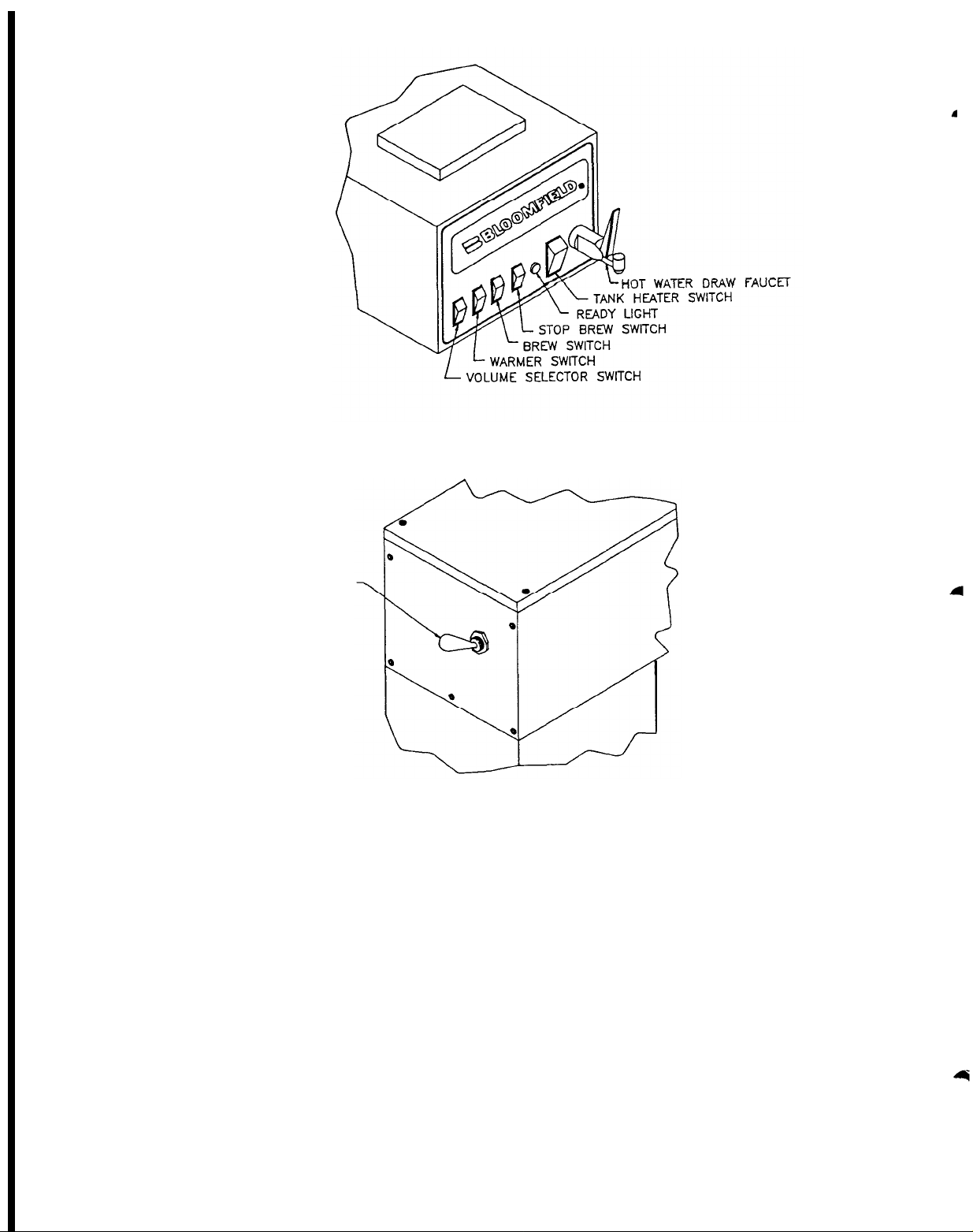
(Figure 1)
FRONT
VIEW
FAUCET
REAR
MAIN POWER SWITCH
(Figure 2)
The
INTEGRITY BREWERS
have
been
flexibility to cover a wide spectrum of
Adjustments on the running thermostat and inlet timer are simple
adjustments
COVERED UNDER ANY WARRANTY SERVICE AGREEMENT.
Brewers must
instructions
easily
accomplished by the purchaser,
be installed in accordance with installation
in the owner's manual for the warranty to be valid.
VIEW
designed with
customer
adjustment
needs.
but NOT
WARNING: DO
INSTALLATION INSTRUCTIONS ARE READ AND FOLLOWED.
NOT
PLUG IN OR
ENERGIZE
THIS
UNIT
UNTIL
Page 3
WARNING:
DO NO PLUG IN OR ENERGIZE THIS UNIT UNTIL INSTALLATION
INSTRUCTIONS ARE READ AND FOLLOWED.
ELECTRICAL INSTALLATION
IMPORTANT: Prior to starting
the electrical hook-up, check
power source and electrical
receptacle for proper single
phase voltage supply.
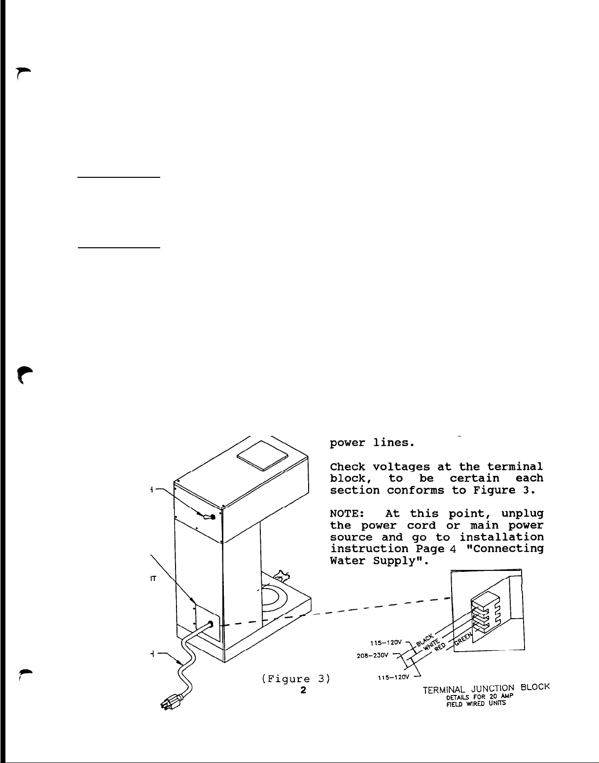
Figure
3 details:
Models 9104 Unit with 3 wire
plus ground requires: 120/208
Volt or 115/230 Volt A.C. 60
HZ.,
Wire,
Single Phase, (3) Three
20 AMP service.
Models 9102 Unit with 2 wire
plus ground, is equipped, (from
the factory),
with power cord
and plug attached. It requires
120 Volt, A.C., 60 Hz., Single
phase (2) Two wire, grounded,
15 AMP service.
CAUTION: DO NOT CONNECT TO A
THREE (3) PHASE POWER SOURCE OR
ANY OTHER THAN AS NOTED IN
FIGURE 3, AS DAMAGES TO THE
UNIT CAN OCCUR THAT ARE NOT THE
RESPONSIBILITY OF
THE
MANUFACTURER OF THE UNIT.
IMPORTANT:
For Power supply,
use #12AWG wire suitable for 75
degrees C.
ONLY.
Wire, plug and connector
must be
Use copper wire
supplied by
the
ELECTRICIAN, for 20 AMP. units.
1.
Recheck at this point, the
Main Power Switch and the
Tank Heater Switch on the
unit front panel must be
in the OFF position.
2.
For
units
electrician
requiring
installed
power cord, remove two (2)
screws from rear access
panels of
brewer
for
access to the installation
junction block.
All wiring must be
accordance with
local
electrical codes.
Do not assume the GREEN earth
ground wire can be used as a
neutral.
The GREEN earth
ground is a protection circuit
not intended as part of the
MASTER SWITCH
ACCESS DOOR
TO TERMINAL BLOCK
CONNECTIONS FOR
115/23OV
POWER CORD SUPPLIED WITH
120V, 15A UNiTS ONLY
.
Page 4

GUIDE TO THE INITIAL INSTALLATION
AND TANK FILLING SEQUENCE
NOTE:
THIS UNIT IS PROVIDED
WITH FOUR (4) 4 INCH LEGS.
THESE LEGS ARE TO BE INSTALLED
ON UNIT BY SCREWING THEM INTO
THE
THREADED
HOLES ON
THE
BOTTOM PLATE.
LEVELING THE UNIT
This is a
installation operation
must
ignored.
not be
For proper unit oper-
ation, it is
very
important
that
overlooked or
very
important
that the unit be level when it
is standing in its installed
location.
The 4 inch legs provided with
the unit can be adjusted to
correctly level unit.
NOTE:
THIS FOLLOWING PROCEDURE
MUST BE PERFORMED TO INITIALLY
FILL WATER TANK.
STEP 1.
Check
the
Main
switch, to be sure it
is in the "OFF" position.
The switch is
located on the rear
upper panel of the
unit.
It must remain
"OFF" until the tank
filling procedure has
been read
and
followed.
STEP 2.
CHECK
HEATER
THAT
SWITCH,
TANK
LOCATED ON FRONT OF
BREWER IS IN "OFF"
POSITION.
STEP 5.
STEP 6.
STEP 7.
STEP 8.
STEP 9.
STEP 10.
STEP 11.
Turn brew selection
switch,
on
front
panel of unit to the
1 gallon position.
Slide brew chamber
into place and place
an
empty
satellite
container on warmer.
CHECK THAT FAUCET IS
CLOSED.
Turn on
water
and
electric at source.
Turn on main power
switch
on back of
brewer.
Press
switch,
brew
wait
start
(2)
minutes and repeat.
Water
flowing
chamber
third
should
from brew
during
cycle
start
the
indicating the tank
is filled with water.
After
remove,
water
empty
stops,
and
replacethe satellite
container under the
brew chamber.
Follow
instructions
for initial brewing
cycle set-up
operation
and
guide.
Page (5).
STEP 3.
STEP 4.
Connect
source to unit.
electrical
(SEE
INSTRUCTIONS - PAGE
2) l
Connect water supply
to
unit.
(SEE
INSTRUCTIONS - PAGE
(4)) -
3
Page 5
CONNECTING WATER SUPPLY LINE TO UNIT
4
Complete the electrical installation
before starting the water connections.
WARNING:
DO NOT PLUG IN OR ENERGIZE THIS UNIT UNTIL
INSTALLATION INSTRUCTIONS ARE READ AND
FOLLOWED.
IMPORTANT: Flush water line until
water runs clear before installing water
line to filter and the unit. Machine
should be connect to COLD WATER LINE.
Before starting water hook-up, check to
be sure the power cord of the unit is
unplugged, or main power source is off.
Unit must be installed on a water line
with a flowing pressure between 20 PSI
and 90 PSI. If water pressure does not
fall into this range, or varies
greatly, a pressure regulator should be
installed.
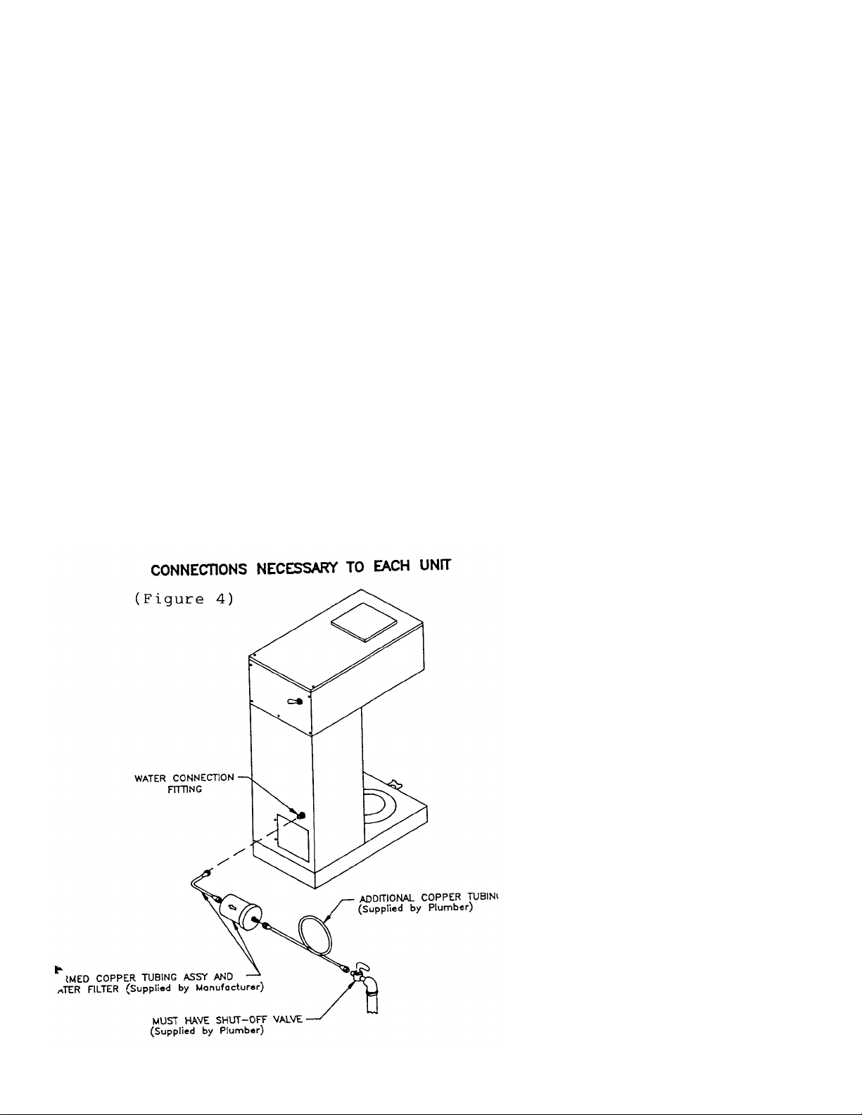
AUTOMATIC BREWERS are supplied with
water line filter which has to be
installed between the machine and water
supply line.
For installation, use 1/4" copper
tubing and fittings. A water shut-off
valve must be installed in the supply
line (not included). For connecting of
the brewer to water supply line, refer
to Figure No. 4.
NOTE: Water line connections to
machine must conform to local codes.
After water hook-up is completed,
continue to follow installation
instructions, page 3 "Guide to the
Initial Installation and Tank Filling
Sequence" to finish the installation
and set-up the unit for brewing cycle.
The National Sanitation Foundation
requests a provision be made in the
incoming water line for flexibility.
This is necessary to allow tilting or
moving the machine for proper cleaning
underneath, etc. A tightly coiled
length of copper tubing located on
either side of the water strainer
would help comply with this request.
Page 6

INITIAL BREWING CYCLE SET-UP AND OPERATION GUIDE
This unit is now connected to
water
supply
electric power source.
and to
the
Check
that installations have been
made as described in electrical
and
water
supply
connection
instruction.
1.
Complete each step in the
following sequence:
A.
Check that main power
switch is
II ON II
and
unit is connected to
power source.
heater
remain
switch
"OFF"
Tank
must
until
STEP "F".
B.
Check
that
brew
selector switch is in
the 1 gallon mode.
C.
Check
that
brew
chamber is in place
and an
satellite
empty
container
is under it with its
faucet CLOSED.
D.
Take
an
decanter
under
faucet
faucet
l/2
water.
hot
and
drawing off
decanter of
This avoids
"spitting"
and
empty
hold
water
open
from
faucet due to trapped
air in
the
water
coil.
E.
Turn "ON" the main
power switch, located
on
upper
back of
brewer.
F.
Now turn
the tank
heater switch to the
"ON"
position.
Switch is located on
the front upper panel
of unit.
2.
3.
4.
Water in the tank will
start heating.
Initial
heating time is
approximately
minutes,
brewer model.
15 to 25
depending on
The GREEN
Ready to Brew light will
turn on when water reaches
brewing temperature.
When GREEN Ready to Brew
light turns ON, Press Brew
Start switch.
Hot Water
will start flowing out of
the brew
chamber,
indicating that the tank
is full of water.
After
water stops flowing from
brew chamber, remove and
empty
container,
the satellite
and place it
back under brew chamber,
with faucet closed.
(Be
sure the brew selector
switch is set for 1 gallon
brewing).
Repeat
STEP 3...after
water stops flowing, you
should have approximately
128 ounces
brim
full
slightly over
of water (2
decanters or
l/2 a
satellite container). If
after completion
of the
cycle you do not have 128
ounces of water,
proceed
as follows:
A.
Check water
supply
line pressure.
BREWER WILL
NOT
OPERATE PROPERLY IF
THE LINE PRESSURE IS
BELOW 20 PSI.
(You
may obtain your PSI
pressure by inserting
a
gauge in
the
incoming water line
supplying the unit.)
5
Page 7
Brew Vol.
Number change
Mark change
on Timer Dial
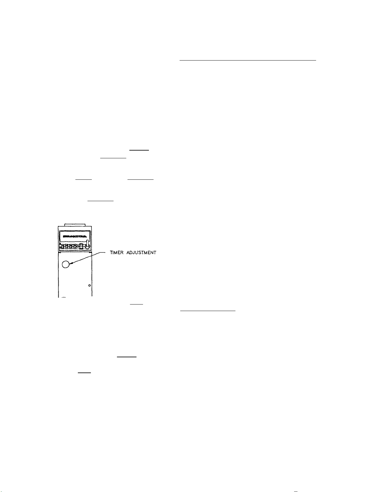
B. Remove Brew Chamber and the
satellite container from
brewer, also the timer
adjustment plug button, (the
2" diameter plug) located on
upper left hand side of
front panel. This allows
access to timer adjustment
knob. Nominal timer setting
for all 3 brew volume
ranges is #4.
C. Turn timer adjusting knob:
switch
Setting
1/2 gal.
1 gal
1 1/2 gal.
1-
on Timer Dial
Plate
11 oz.
22 oz.
33 oz.
1-
Plate
3 oz.
5 1/2 oz.
8 oz.
D. Replace brew chamber and the
empty satellite container with
faucet closed. Set brew selector
switch at 1 gal. and start a brew
cycle.
1. CLOCKWISE: to a higher
number, to increase volume.
2. COUNTER-CLOCKWISE:
to lower number to decrease
volume.
CAUTION!
The timer is very
sensitive, so make
adjustments one (1) mark at
a time!
Approximate changes in
the ounces of water
delivered when knob is
rotated (1) one number
(example #5 to #6) or (1)
one mark (ea. division
between numbers), is as
specified.
E. Check for 128 oz. (1 gal.) water
delivery volume. Repeat
adjustment procedure until
desired water volume (128 oz.) is
achieved during a brew cycle.
F. After water volume has been checked
for proper delivery, check
temperature of brewing water as
follows:
- Ready to Brew light is on
- Run a brew cycle of water and
check the temperature of water with
a thermometer
- Proper operating temperature from
Brew Chamber should be 190 F +/- 5
at mid cycle.
- If thermostat needs adjustment
refer to "Operating Thermostat
Adjustment" Page 9.
BREWING OF COFFEE
Depending on the brewer model, the
brewing capacities are 1/2 - 1 gal.
(9102) and 1-1 1/2 gal. (9104). The
brewing procedure is the same for
either model. Always check the brew
selector switch to be sure it is in the
brew mode you desire.
6
Page 8
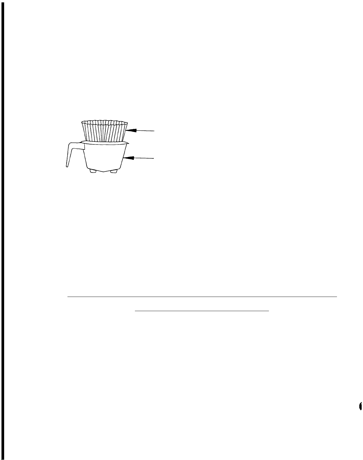
1.
Remove brew chamber from
unit and place
paper
chamber.
filter
Add your choice
of ground coffee.
one (1)
into
brew
Shake
brew chamber to level off
the
coffee,
slide brew
chamber into place.
3.
4.
When GREEN Ready to Brew
light is on, press the
Brew Start switch.
When
coffee stops flowing from
the
brew
chamber the
freshly brewed coffee is
ready.
Remove brew chamber and
discard paper filter and
coffee grounds.
2.
paper filter
brew chamber
Place an empty satellite
container
chamber.
under
brew
Make sure faucet
is closed.
IMPORTANT:
Always use an
empty satellite container
when
starting a
brew
cycle.
5.
When GREEN Ready to Brew
light turns ON again, the
brewer it
ready
another brewing cycle.
6.
To keep the coffee hot,
the brewer is
equipped
with a warmer which is
activated by a
switch
located on the upper front
panel.
glow,
A RED light will
indicating that
warmer is "ON1'.
IMPORTANT:
1. Warmer should be turned
off when not in use.
2.
DO NOT leave empty satel-
lite on warmer that is
"ON" .
3.
DO NOT leave coffee on
warmer over night.
for
BY-PASS:
Model 9104 Uses A By-Pass Valve During Brewing
SET UP AND ADJUSTMENT
The unit leaves the factory
with the By-Pass Valve set at
the 25% by-pass volume which is
the smaller of the flow set
gauges,
however, if
the
location has:
A. Softened Water:
1.
supplied by their
community water source or
2. their own water softener,
7
or
B. The finished brew is too
strong; when:
1.
the correct amount of
coffee grounds is used,
approximately 6 to 8 ounces
and,
2.
the correct volume (128
ounces) of water flows into the
satellite,
Page 9
a
the by-pass valve must be readjusted or opened toward the
larger gauge and size which is
approximately a 50% by-pass of
water volume.
Re-adjustment
of the by-pass
valve prevents the coffee bed
from rising above the filter
paper
finished brew.
and flooding into the
Re-adjustment
also aids in setting the level
of finished brew strength for
local coffee drinking quality.
NOTE:
NEVER BE MADE UNLESS SOFT WATER
CONDITION EXISTS OR AN ADJUST-
MENT FOR COFFEE STRENGTHS IS TO
BE MADE.
WARNING:
THIS ADJUSTMENT MUST
Turn
off
the Tank
Heater Switch and disconnect
power supply to
removal of
Brewer before
any
panel or
replacement of any component.
Remove the two (2) screws
1.
holding the top panel.
Slide panel back and up to
remove.
Lift Water Basin Pan (#7)
2.
and move aside.
Remove
3.
(#16)
counter-clockwise
soft water valve
and
turn
screw
enough
to accept large Flow Set
Gauge.
Replace soft water valve
4.
in brewer.
Replace water basin and
5.
top cover.
Plug in Brewer and turn on
6.
Tank Heater Switch.
NOTE:
Brewing time should be
between 6 and 8 minutes. If
brew time exceeds 8 minutes
after opening valve to 50% open
soft
water
valve
1/8
turn
further and re-time brew cycle.
If brew time still exceeds 8
minutes,
contact
Bloomfield
Industries.
WIRE GAUGE
USE DRILLS OR WIRES OF THE DlAMETERS
SPECIFIED. TO ADJUST BY-PASS SETTlNGS
BY-PASS
25%
BY-PASS VALVE
-/
3/64 DIA I
FLOW SET GAUGES
L
FLOW SET GAUGE
8
BY-PASS
50%.
11/64 DIA
Page 10

IMPORTANT: UNIT MUST BE DISCONNECTED FROM ELECTRICAL SOURCE
BEFORE ANY SERVICE
IS PERFORMED.
FRONT PANEL REMOVAL
To remove the front panel for
service,
remove (6) screws and
lift panel away from body.
BASE COVER/WARMER ELEMENT REMOVAL
Remove
cribed above).
front panel
Loosen faucet
(as des-
support bracket screws and drop
bracket to provide clearance.
Slide base cover forward to
disengage
upward.
clips
Warmer
and
lift
element is
attached to underside of dome
shape by a retaining bracket.
and nut.
sequence.
Reinstall in reverse
Adjust
Faucet
bracket with satellite resting
on warmer.
Bracket end should
just touch faucet shank.
FRONT VIEW
FRONT PAN EL
3.
Slide cover back and lift
off.
4. Turn Thermostat adjusting
shaft.
ments
ature,
clockwise
temperature.
Clockwise adjust-
INCREASES temper-
and
counter-
DECREASES
For proper
operation of the unit and
optimum
extraction of
coffee, thermostat should
cycle off between
195 F
and 205 F.
5. Reconnect power to brewer.
To check temperature, unit must
be energized:
B.
Using a
mercury
thermometer:
1. Remove brew chamber and
spray head.
2.
Leave empty satellite on
lower warmer, with cover
off,
and faucet closed.
3. When ready light comes ON,
press brew button
4. A stream of hot water will
come out of brewer.
the
thermometer
stream
bulb of
into
and
read
Place
the
the
the
temperature.
5. If
previous
desired
necessary,
steps
temperature is
repeat
until
achieved.
SLIDE
FOR’WRD
OPERATINGTHERMOSTATADJUSTMENT
Whenever running
adjustment becomes
thermostat
necessary,
proceed as follows:
A.l. Check that power to brewer
is disconnected.
2. Remove two (2) screws from
top cover.
9
IMPORTANT:
should be
Tank
thermostat
adjusted so
that
water temperature never exceeds
205 F.
REAR
VIEW
-
THEMOSTAT
r
I
ADJUSTING SHAFT
Page 11

TIMER ADJUSTMENT
Timer adjustments are made with
the brew selector switch in the
1 gallon position. These units
are equipped with an adjustable
timer to permit brewing l/2 -
1 gallons or 1 or 1 l/2 gallons
with
the
flip of a
brew
selector switch, depending upon
brewer
model.
Refer to
detailed instructions on Timer
Adjustments - Page 6 - items
"B" through "E".
Remove brew chamber.
1.
2. Remove timer adjuster plug
button.
3.
To INCREASE time of water
flow, turn timer adjusting
knob
clockwise.
DECREASE time of
To
water
flow, turn timer adjusting
knob counter-clockwise.
Replace plug button and
4.
brew chamber.
TIMER ADJUSTMENT
Slide cover back.
3.
cover aside.
4.
Disconnect
water
hose, elbow, vent tube and
inlet
pan.
5.
Disconnect
elbow
Remove basin pan.
from basin
flare
fitting on the following
tubing assemblies:
A. Tube assembly: needle
valve to tank cover - dis-
connect at needle valve.
B.
Tube assembly:
cover to faucet.
Discon-
nect at faucet valve.
6.
Disconnect wires
thermostat.
7.
Disconnect wires
heating element.
On 120
Volt unit also disconnect
wires from the high limit
control.
8.
Loosen center
screw on
tank hold down bracket.
Remove hold down bracket
9.
by
sliding
slotted end
the
off
locking stud.
Remove cover assembly from
10.
tank by lifting it out.
Set
inlet
nut
tank
from
from
short
the
TO REPLACE TIMER ASSEMBLY
Disconnect cord from elec-
1.
trical
outlet/turn
off
power source.
Remove front panel.
2.
Remove timer knob and the
3.
three (3) screws holding
timer to bracket.
Disconnect timer wires.
4.
5. Replace
timer
following
reverse procedures.
TO REPLACE WATER COIL AND/OR
HEATING ELEMENT ASSEMBLY
1. Disconnect unit from power
supply and shut off water.
Open faucet momentarily,
to relieve pressure.
2.
Remove two (2) screws from
rear of top cover.
TO REMOVE
HEATING
ELEMENT
ASSEMBLY
1. Remove tank lid assembly
- see steps 1 through 10 of
"To
Replace
Heating
Element Assembly".
2. Remove two (2) hex nuts
and pull out
elements from
heating
mounting
holes in cover.
TO REMOVE WATER COIL ON WATER
FAUCET MODEL
TO REMOVE WATER COIL ASSEMBLY
Remove tank
1.
lid -
see
steps 1 through 10.
Remove both copper tubing
2.
assemblies fromwater coil
fittings.
3.
Remove
two
(2)
nuts
holding water coil to tank
lid assembly.
10
Page 12

NOTE:
On the Model 9104 it is
necessary to remove the tank
heating element before removing
the water coil.
TO REPLACE THERMOSTAT
1. Disconnect power supply to
brewer.
2.
Remove two (2) screws from
rear of top cover.
3.
Slide cover back.
Set
cover aside.
4.
Disconnect
wires
from
thermostat.
5. Loosen two
securing
(2)
thermostat to
screws
bracket.
6. Loosen and remove jam nut
from
fitting,
securing
thermostat capillary line
into the top of the cover.
7.
Lift out the thermostat
capillary
sensing
bulb
from the cover.
IMPORTANT:
thermostat
When remounting a
capillary
sensing
bulb through the cover, be sure
a new seal washer
below
capillary
capillary
the
fitting on
line.
line
is placed
Push
through
the
the
the
cover until the fitting seats.
Tighten the capillary locking
nut enough to insure no water
leakage.
Extreme tightening is
not necessary.
When replacing heating element
assembly or water coil,
should
gaskets.
list.)
also
replace
(Refer to parts
Before
setting
you
the
the
cover assembly to the tank,
make sure the tank cover gasket
is
properly
seated in
the
flange of the cover.
TO REPLACE READY LIGHT
1. Disconnect cord from electrical
outlet/turn
off
power source.
2.
Using thin screw driver,
pry out pilot light from
mounting hole, disconnect
leads.
3.
Replace pilot light fol-
lowing reverse procedure.
TO REPLACE WARMER AND BREW
SWITCHES
1. Disconnect cord from electrical
outlet/turn
off
power source.
2.
Using thin screw driver,
pry
out
switch
from
mounting hole, disconnect
leads.
3.
Replace switch following
reverse procedure.
TO REPLACE SOLENOID VALVE AND
WATER CUSHION TUBE ASSEMBLY
1. Disconnect cord from electrical
outlet/turn
off
power source.
2.
Turn off water supply.
3.
Remove
water
connection
and hex nut holding inlet
fitting into back of unit.
4.
Remove front panel.
5.
Remove
the flare
connection from the "T"
top outlet and gently move
tubing aside.
6.
Pull
solenoid
forward
slightly and lift up to
release
mounting
disengage
it
from
bracket
inlet
the
and
fitting
from hole in back panel.
7.
Carefully pull
assembly
out to
access to
solenoid
wiring
gain
and
rubber tube.
8.
Remove
wires
from
solenoid.
9.
Remove rubber tube.
10.
Solenoid
assembly
with
water cushion tube can now
be removed for complete
servicing.
11.
Replace assembly by fol-
lowing reverse procedure.
TO REPLACE TANK
1. Disconnect cord from electrical
outlet/turn
off
power source.
2.
Turn off water supply and
remove
water
connection
11
Page 13

from
inlet
fitting on
back of brewer.
Position
3.
drain
fitting
over drain facility and
unscrew
CAUTION!
drain
WATER MAY BE
cap.
HOT.
4.
Remove
back panel,
the
projects,
the
lower
through which
drain
by removing the
body
fitting
two (2) screws.
5.
Remove
the
basin
back
panel panel, by removing
the five (5) screws and
carefully drop downward,
make sure wiring to main
switch is protected and
not subject to damage.
6.
Proceed
#2
with
through
operations
# 10 ,
described in "TO REPLACE:
WATER
MENT",
7.
Remove the two (2) nuts
COIL/HEATING
Page 10.
ELE-
securing tank retaining
brackets to tank screws.
Remove the two (2) nuts
a.
securing the two (2) tank
retaining
basin
bottom.
brackets to
Remove
brackets.
9.
Rotate
tank
counter-clockwise,
the left) 90
until
drain
assembly
(l/4
turn)
tube is
(to
centered on slot in tank
mounting tray.
out
carefully,
Then lift
making
sure drain tube passes
through
slot and clears
needle valve.
10. Assemble
in
reverse
sequence.
HI-LIMIT TEMPERATURE,
SAFETY
CONTROLS
MODEL 9102-120 V, 15 AMP UNIT
This
model
has a
self
resetting control, mounted on
the
tank
cover,
automatically
and will
"OPEN"
when
normal tank temperatures have
been
when
exceeded,
tank
has
and
sufficiently
"RESET"
cooled down.
1. Disconnect cord from electrical
outlet/turn
off
power source.
Remove two (2) screws from
2.
rear of
top
cover
and
slide cover aside.
Remove wires from Hi-Limit
3.
Control,
mounted
under
clip on tank cover.
4.
Slide
from under
Hi-Limit
clip
Control
and
replace with new control.
Make sure that there is
sufficient
tension
from
the clip to insure proper
contact between tank cover
and bottom of Hi-Limit
Control.
5. Reconnect wires.
NOTE:
IF TERMINALS OR WIRING
APPEARS DISCOLORED
FROM
HEATING, REPLACE TERMINAL
ON NON-OXIDIZED WIRE ENDS.
MODEL
9104-115/230
V, 20 AMP
UNITS
This
model
resetable
has a
control,
against the tank body.
automatically
"OPEN"
manually
mounted
It will
when
normal tank temperatures have
been
exceeded,
but must be
manually reset to restore elec-
trical
heating,
continuity
for
when tank has suffi-
tank
ciently cooled down.
RESETTING THE HI-LIMIT SAFETY
CONTROL
1.
Pry
out the small plug
button in the front panel
of the body.
2. Using a non-electrically
conductive dowel or rod,
(i.e.
eraser
end of a
wooden pencil) press the
small reset button located
in
the
center of
the
12
Page 14

control.
sufficiently cooled down,
the control will "SNAP" to
the
restore power to the tank
heater.
3.
Replace plug button.
REPLACEMENT
CONTROLS
1.
Disconnect
power source.
Remove body front panel,by
2.
removing
and
lifting panel
from body.
3.
Loosen
bracket
Control,
slide assembly from its
mounting bracket.
Disconnect
4.
safety control.
Remove
5.
Limit Control on bracket,
as shown in Figure
using the screws and nuts
originally supplied.
If tank has
"ON"
position
OF
HI-LIMIT
brewer
six (6) screws
screw
with
holding
Hi-Limit
to the unit, and
wires
and
replace Hi-
and
from
away
from
"A"
CLEANING THE SPRAY HEAD
1. Remove brew chamber.
2. Rotate spray head ears out
of locking cup by pushing
up as you rotate it out of
locking groove.
3.
Clean lime and wipe oil
from both sides of spray
head, being sure all spray
head holes are fully open.
4.
Clean
entire area
over
brew chamber with a damp
cloth.
5. Replace spray head, being
sure spray head gasket is
in place in cup.
Spray
head tabs must be in the
UP position.
Rotate fully
into locking grooves.
6. Reinstall bracket assembly
into its mounting bracket
and position the face of
the
safety
control
directly against the side
of the tank, so control is
firmly
Tighten
touching
mounting
tank.
screw,
making sure that Hi limit
Control is
still
-tight
against tank body.
7. Replace front panel.
13
Page 15

HOT WATER FAUCET SYSTEM PARTS LIST
REF
PART NO.
DESCRIPTION
1
8551
-
250 FAUCET (INCLUDES
#2
, #3 &.
#4 )
2
8551
-
100A
WASHER
3
8551
-
100B
7/16
EXTERNAL TOOTH LOCK WASHER
4
8551
-
100C
HEX LOCK NUT
5
9102
-37
FAUCET TUBE ASSEMBLY
6
9102
-58
FORMED I
NLET TUBE ASSEMBLY
7
8551
-30
1/4
MALE FLARE x
1/8
FPT FITTING
8
8514
-26
NEEDLE VALVE
9
9102
-25
OUTLET TUBE ASSEMBLY
10
8704
-25
WATER CUSHION TUBE ASSEMBLY
11
8812
-57
UNION,
1/4
FLARE
12
9102
-56
COUPLING,
1/4
FEMALE FLARE
13
9102
-55
TEE.
1/4
FLARE (M
-M-F) 14
9102
-38
WATER TUBE ASSEMBLY
15
9102
-8
ELBOW, PIPE TO HOSE
16
8541
-
120 SOLENOID VALVE ASSEMBLY
17
8706
-
102 REDUCER ADAPTOR
18
9012
-24
TEE,
1/4
FLARE x
3/8
MPT
19
8766
-2
WATER INLET HOSE
20
8540
-30
ELBOW
21
8540
-6
HOT WATER COIL ASSEMBLY
22
8043
-30
GASKET
23
8941
-21
7/16
-20 x
3/16
THICK BRASS LOCK NUT
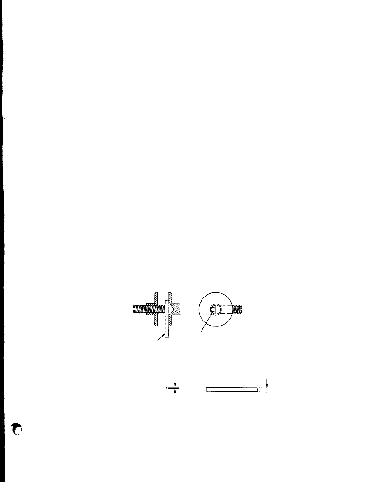
1. 8551-275 Repair Kit (sold as
Kit only)
A.
I
Handle (Color
- Red) B. I
Valve —
Stem C. I
Valve Disc
D.
Kit "0"Ring
- #6. 7, & 8
E. Contains
Tee Nut
G.
I
Guide H. I
Bushing
Instruction Card (Not Shown)
2.
8551-275B Str
eam Straightener (Not Shown)
3.
8551-100A Washer Rubber
4.
8551-100B 7/16
External Tooth Lock Washer
5.
8551-100C Hex. Lock Nut
SEALS AVAILABLE
6.
8551-200B "0"
Ring Stem Seal
5/16
Outside Dia.
7.
8551-200A "0"
Ring Seal
1/4
Outside Dia.
8.
8551-200C
"0"
Ring Spout Seal
3/8
Outside Dia.
C.
8551-275A Valve Disc
TOOL AVAILABLE
9.
8551-200E Adaptor Tool
— Service Wrench
NOTE :
FOR COMPLETE FAUCET ASSEMBLY, ORDER PART NO. 8551-250
INCLUDES ITEMS 1, 2, 3 AND 4.
HOT WATER FAUCET REPLACEMENT LIST
Ref. No. Part No. Description
14
Page 16

THERMOSTAT AND TANK COVER
IDENTIFICATION AND REPLACEMENT INFORMATION
PARTS LISTING FOR TANK COVER ASSEMBLY
REF. NO. PART NO. DESCRIPTION MODELS
1 8512-51 THERMOSTAT ALL
2 8043-11 OUTLET ELBOW ALL
3 8706-20 VENT TUBE ALL
4 8706-6 INLET ELBOW ALL
5 8514-68 TANK COVER SUB ASSEMBLY ALL
6 3-100 #6-32 x 1/4 ROUND HEAD SCREW ALL
7 8043-83 HI-LIMIT THERMOSTAT 9102
8 8543-73 #4-40 x 1 1/2 PAN HEAT SCREW ALL
9 8543-74 #4-40 HEX NUT ALL
10 8706-68 WATER INLET TUBE ALL
11 8760-44 HEATING ELEMENT, 240V-4200 WATTS 9104
12 9102-9 HEATING ELEMENT, 120V-1675 WATTS 9102
13 8043-30 HEATING ELEMENT GASKET ALL
14 8043-12 TANK COVER GASKET ALL
15 8540-6 HOT WATER COIL ALL
16 8941-21 7/16 HEX NUT ALL
17 8043-28 1/2-20 HEX NUT ALL
18 8512-41 SEAL WASHER ALL
15
Page 17

COMPLETE SPARE TANK COVER ASSEMBLIES
(2C)
Seal Ring
(FOR PARTS LIST SEE PAGE 19)
PART NO. DESCRIPTION MODEL
9102-300 Tank Cover Assembly, 1675 W/120V with Water Coil 9102
9104-300 Tank cover Assembly, 4200 W/240V with Water Coil 9104
All parts are mounted to cover
COLD WATER ENTRANCE SOLENOID VALVE PART NO. 8541-120
(Consist of Valve and Flow Control)
SOLENOID VALVE REPLACEMENT PARTS
(For Black Coil Valve)
(No Parts Sold Separately)
(1) 8541-120CS Coil Assembly - 120V
(2) 8541-120K Solenoid Repair Kit
Vacuum Pac consist of :
(2A) Spring
(2B) Plunger
(2C) Seal Ring
(2) 8541-120JS Solenoid Repair Kit
Vacuum Pac consist of :
(2A) Spring
(2B) Plunger
(3) 8541-120KS Solenoid Repair Kit
Vacuum Pac consist of :
(2A) Spring
(2B) Plunger
(2C) Seal Ring
(2D) Service Wrench
(3A) Flow Control
(4) 8541-120F (5A) Flow Control
(5) 8541-120WS (20) Service Wrench
16
Page 18

17
Page 19

REF NO.
PART NO.
REPLACEMENTS PARTS LIST
All Models
DESCRIPTION
MODEL(S)
USED ON
1
2
3
4
5
6
7
8
9
10
11
12
13
8543-52
8593-17
8593-18
9102-4
8201-5
8540-30
9102-18
8043-47
8043-5
8543-23
8593-27
9104-l
9102-l
Screw,
#8x 3/8" LG
Hinged Cover
Hinge Wire
Basin Cover
Nut, #10-24x 3/8" Hex
Elbow -
Plastic
Basin Pan Sub-Assembly
Screw, #l0-32 x l", LG
Hold Down Strap Assembly
Tinnerman Nut
Switch, Main
Switch, Main
Back Panel, Basin
ALL
ALL
ALL
ALL
ALL
ALL
ALL
ALL
ALL
ALL
9102
9104
ALL
14
15
16
17
18
19
20
21A
21B
3-100 Screw,
8706-111
8706-26
8706-188
9104-15
9102-480
8043-13
9102-7
9104-7
Screw,
By-Pass Valve
Connector Tube
"T" By-Pass Tube Assembly
Tube, Water outlet
Spray Elbow
Basin Welded Assembly
Basin Welded Assembly
#6-32 x l/4", LG
By-Pass Adj.
18
ALL
9104
9104
9104
9104
9102
ALL
9102
9104
Page 20

REF NO.
PART NO.
DESCRIPTION
MODEL(S)
USED ON
22
23
24
25
26
27
28
29
30A
30B
31
32
33
8543-69
8543-42
8543-44
9102-27
8707-28
8707-34
8718-31
8812-79
8707-34
8528-40
8551-250
8551-1OOA
8551-100B
Bushing, Plastic
Gasket,
Sprayer, Disc.
Switch, Vol Select
Switch, Brew
Switch, Warmer
Pilot Light, Green
Switch, Stop
Switch,
Switch, Tank Heater
Faucet,
Washer, Rubber
Lock washer, 7/16" I.D.
Spray Head
Tank Heater
Hot Water
ALL
ALL
ALL
ALL
ALL
ALL
ALL
ALL
9102
9104
ALL
ALL
ALL
34
35
36
37
38
39
40
41
42
43
44
8551-1OOC
8706-9
8707-3
8707-2
9102-57
8766-2
9102-8
8710-10
8812-57
9102-56
9102-55
Nut, 7/16-20, Faucet
Wire Rack
Screw,
Handle
Brew Chamber Only
Water Inlet Hose
Brass Fitting Elbow
Nut, #7/16-20, Inlet
Fitting
Fitting, Water Inlet
Fitting,
Fitting, Tee
#l0-32 x 5/16", LG.
Coupling
19
ALL
ALL
ALL
ALL
ALL
ALL
ALL
ALL
ALL
ALL
ALL
Page 21

REF NO.
PART NO.
DESCRIPTION
MODEL(S)
USED ON
45
46
47
48
49
50
51
52
53
54
55
9102-38
Tubing Assembly -
Inlet/Solenoid
8704-25
8706-102
8541-120
9012-24
9102-9
Cushion Tube Assembly
Fitting, Reducer
Solenoid Valve, 120V
Fitting, Tee
Tank Element, 1675 Watts,
120v
8540-4
Tubing Assembly, Inlet
9102-9 Tubing Assembly, Sol/N.
Valve
8540-6
8043-30
8514-26
Hot Water Coil Assembly ALL
Gasket,
Element/Water Coil
Needle Seat Valve
ALL
ALL
ALL
ALL
ALL
9102
9104
ALL
ALL
ALL
56
57
58
59
60
61
62
63
64
65
8914-21
8551-30
9102-58
9102-37
8043-11
8512-51
8706-20
8512-41
8043-28
8706-6
Nut, #7/16-20, Water Coil
Brass Fitting - Pipe/Flare
Tubing Assembly - N.
Valve/Coil
Tubing Assembly -
Faucet/with Coil
Outlet Elbow
Thermostat - R.S.
Vent Tube
Seal Washer, Thermostat
Nut, #l/2-20, Element
Inlet Elbow
20
ALL
ALL
ALL
ALL
ALL
ALL
ALL
ALL
ALL
ALL
Page 22

REF NO. PART NO. DESCRIPTION MODEL(S)
USED ON
66 8514-68 Tank cover - S/A ALL
67 8043-83 Hi-Limit Thermo 9102
68 8043-12 Gasket, Tank Cover ALL
69 8543-73 Screw, #4-40 hex ALL
70 8543-74 Nut, #4-40 11/2" Lg ALL
71 8706-68 Water Inlet Tube ALL
72 8760-44 Tank Element, 4200W, 240V 9104
73 8043-506 Acorn Nut, #8-32 ALL
74 8942-92 Nut, Hex Keps, #8-32 ALL
75 9102-23 Bracket, Tank Mtg. ALL
76 9102-32 Tank Assembly ALL
77 8593-44 Drain Cap ALL
78 6440-1 Seal, Drain Tube ALL
79 9102-34 Front Panel - Auto. ALL
80 8706-75 Plug Button - Large ALL
81 8033-60 Plug Button - Small ALL
82 9102-20 Base Cover ALL
83 8572-18
84 8704-20 Retainer, Warmer Element ALL
85 6440-57 Nut, #1/4-20 Hex ALL
86 9102-16 Bottom Panel Assembly ALL
87 6407-10 Screw, #10-32 x 1/4", Lg ALL
88 9102-49 Faucet Support ALL
Warmer Element, 100 W, 120 V ALL
89 8861-16 Nut Hex, Keps, #6-32 9104
21
Page 23

REF NO.
PART NO. DESCRIPTION
MODEL(S)
USED ON
90
91
92
93
94A
94B
95
96
97
98
99
100
8552-50
7200-6x
8718-48
8861-23
9102-35
9104-35
9102-28
8516-1500
8552-18
616-5
9102-22
8574-10
Hi-Limit Thermo., Manual
Reset
Screw,
8-32 x 5/16 Lg
Bracket, Hi-Limit
Screw,
#8 x 3/8", Lg
Body & Base S.A.
Body & Base S.A.
Timer,
12OV, with Dial &
Knob
Leg,
Black Plastic, 4" Lg.
Terminal Block
Screw,
Cover,
#6-32 x 3/4", Lg.
Base Back
Back Cover - Electrical
9104
9104
9104
ALL
9102
9104
ALL
ALL
9104
9104
ALL
9104
101
102
103
104
105
SA 9052
9102-53
35-210
6407-15
9102-41
Strainer
Back Cover - Electrical
Cord Grip - Heyco
Cord & Cap Assembly
Brew Chamber Assembly
22
ALL
9102
9102
9102
ALL
Page 24

23
Page 25

REPLACEMENT PARTS LIST
REF. NO.
PART NO.
DESCRIPTION
1
9105-2 SATELLITE COVER ASSEMBLY
REF. NO.
PART NO.
DESCRIPTION
12
8600-17 SHIELD CAP
MODEL NO. 9105 SATELLITE
REPLACEMENT PARTS LIST
MODEL NO. 9105 SATELLITE
2 9105-21 BODY AND TANK WELD ASSEMBLY
3 9105-10 SHOULDER SCREW
4 7200-6X #8-32 x 5/16 PN. P. SS
5 9105-17 WASHERS, BELLEVILLE
6 9105-5 LATCH, SATELLITE COVER
7 8705-2 NYLON WASHER
8 9105-15 BUTTON-LATCH STOP
9 9105-11 HANDLE
10 9102-22 BUSHING
11 9105-20 FAUCET AND SIGHTGLASS ASSEMBLY
REPLACEMENT PARTS LIST
FOR FAUCET ASSY. ONLY - PART NO. 9105-20
13 8700-25 J CAP WASHER
14 8600-20 GAUGE SHIELD (ALUMINUM)
15 8600-22 SHIELD GLASS
16 8705-11 B BASE WASHER
17 8705-11 G SHIELD BASE
18 8600-24 SHANK ASSEMBLY
19 8705-11 L UPPER ASSEMBLY-BLACK BONNET
20 8700-25 L SEAT CUP
21 9105-30 FAUCET BODY
22 9105-25 FAUCET BODY ASSEMBLY
24
Page 26

REPLACEMENT PARTS LIST
MODEL NO. 9106 WARMER
REF NO. PART NO. DESCRIPTION
1 9102-49 FAUCET SUPPORT BRACKET
2 6407-19 SCREW, #10-32 x 1/4 LONG
5 8765-8 LABEL
4 6710-23 ON-OFF SWITCH. 120V
5 9106-4 BOTTOM PLATE SUB-ASSY
6 8543-52 SCREW, #8 x 3/8
7 8033-55 LEG LEVELER
8 8033-56 LEVELER CAP
9 8201-5 HEX. NUT, #10-32 x 1/4
10 8703-26 RETAINER
11 8572-18 HEATING ELEMENT
12 9106-7 TOP AND BODY SUB-ASSY
13 35-210 CORD GRIP
14 8841-8 CORD AND CAP ASSY
25
Page 27

Warranty
BREWER WARRANTY IS VOID IF:
For a period of one (1) year
from date of installation, all
Other than genuine Bloomfield
replacement parts are used.
defective parts on Bloomfield
equipment will be replaced free
of charge, providing parts did
not become defective through
accident, neglect,
installation,
mishandling or
improper
damage in transit. The service
necessary to
replace these
Brewer is plugged into voltage
other than specified on serial
plate.
Recommended Bloomfield
vicing
procedures
are not
ser-
followed.
defective parts will also be
free of charge, provided this
service
is performed by an
authorized BLOOMFIELD service
station,
wherever
authorized
service is available.
How to Order -
Individual uses and owners must order replacement parts thru
their distributors or the local authorized service station.
Terms -
Prices,
terms, designs,
materials,
weights,
specifications and dimensions for equipment or parts are subject
to change without notice.
Service Information
that contained in this manual, call Bloomfield’s toll free number
(800) 621-8556.
Be
prepared to give the Model and Serial Numbers of your brewer,
- To obtain service assistance in addition to
as well as the problem and the trouble-shooting steps already
taken,
to the service technician when calling for assistance.
26
 Loading...