

Page 1
WELLS BLOOMFIELD, LLC
2 ERIK CIRCLE, P. O. Box 280 Verdi, NV 89439
telephone: 775-689-5707
fax: 775-689-5976
www.wellsbloomfield.com
600
INSTALLATION INSTRUCTIONS
SOLENOID VALVE RETROFIT KIT NUMBERS
84571 84572 84575 84574
86606 86644 86650
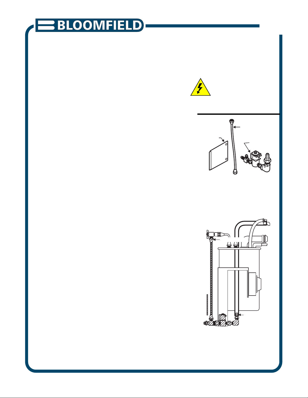
1. REMOVE EXISTING SOLENOID (See figs. 1 and 2)
a. Disconnect brewer from electric power and shut off water
supply.
For brewers with faucet, open faucet to bleed off water
pressure.
b. Remove TOP PANEL, FRONT PANEL and SOLENOID
ACCESS DOOR.
c. Disconnect wires to solenoid.
Remove silicone SUPPLY HOSE from solenoid.
d. For brewers with faucet, disconnect FAUCET SUPPLY
TUBE from solenoid and faucet shut-off valve.
Discard this tube.
e. Remove BRASS NUT from INLET FITTING.
Lift solenoid / timer / bracket assembly from mounting clip.
f. Loosen screws on bottom of solenoid and separate solenoid
from bracket.
Remove solenoid and fittings from cabinet.
Reinstall bracket on mounting clip.
CAUTION:
ELECTRIC SHOCK
HAZARD
Unplug brewer before beginning
conversion.
ACCESS
DOOR
Fig. 1
NOTE: TYPICAL INSTALLATION
SHOWN. ALL INSTALLATIONS ARE
SIMILAR. DETAILS MAY VARY.
DISCONNECT
FAUCET SUPPLY TUBE
BRACKET
ACCESS DOOR
Fig. 2
REMOVE SHADED COMPONENTS
* SOLENOID ACCESS DOOR
* SOLENOID AND FLOW CONTROL
* INLET FITTING, TEE & ADAPTERS
FAUCET
SUPPLY TUBE
SOLENOID
ASSEMBLY
TIMER
SILICONE SUPPLY HOSE
DISCONNECT
PRINTED IN UNITED STATES OF AMERICA
p/n 75909 Rev. A ECN-13394 I 600 080211 cps
1 of 3
Page 2
CAUTION:
ELECTRIC SHOCK
HAZARD
Unplug brewer before beginning
conversion.
SOLENOID
Fig. 3
ROUTE HOSES
AS SHOWN
INSTALL SPLIT BUSHING
Fig. 4
SWIVEL
NUT
BRAIDED
HOSE
ASSEMBLY
SPLIT
BUSHING
ACCESS
DOOR
JUMPER
WIRE
BUTTON
PLUG
TOP VIEW
2. INSTALL NEW SOLENOID (See figs. 3, 4 and 5)
a. For brewers with faucet, attach faucet supply BRAIDED
HOSE to SOLENOID.
Push the hose fully onto the bypass outlet (the side
without a solenoid coil).
b. Assemble the SOLENOID to the new ACCESS DOOR.
Coil should be at the bottom as shown in fig. 3.
c. Route the silicone SUPPLY TUBE through the 3rd hole
(from the front) then out the access door opening.
Attach tube to SOLENOID. Push the tube fully onto the
controlled outlet (the side with the solenoid coil).
d. For brewers with faucet, route the BRAIDED HOSE
through the 1st hole (from the front). Connect the flare
SWIVEL NUT to the end of the braided hose. Rotate
the FAUCET SHUT-OFFVALVE as needed
(approximately 45º) and connect the swivel nut to the
valve. Verify all connections are tight.
e. Assemble the ACCESS DOOR / SOLENOID to the
cabinet. Connect wiring to the solenoid.
f. Turn water supply ON. Check for leaks.
g. Insert BUTTON PLUG in the hole formerly occupied by the
inlet fitting.
h. Reinstall TOP PANEL and FRONT PANEL.
Reconnect unit to electric power and test for proper operation.
ROTATE FAUCET
SHUT-OFF VALVE 45º
ATTACH PLASTIC
HOSE TO OUTLET
WITH SOLENOID:
* PUSH HOSE
FULLY AGAINST
VALVE BODY
ATTACH BRAIDED HOSE
TO OUTLET WITHOUT
SOLENOID (BYPASS):
* PUSH HOSE METAL
FITTING FULLY AGAINST
VALVE BODY
Fig. 5
600 p/n 75909 Instr Retro Solenoid Valve
2 of 3
Page 3

Fig. 6 FAUCET HOSE INSTALLATION AND REMOVAL
KIT IDENTIFICATION
KIT NO. 84571
120 volt coffee brewer.
Solenoid 1 x .75 gpm
KIT NO. 84572
120 volt coffee brewer with faucet.
Solenoid 1 x .75 gpm plus faucet bypass
KIT NO. 84574
240 volt brewer
Solenoid 1 x .75 gpm
KIT NO. 84575
240 volt coffee brewer with faucet.
Solenoid 1 x .75 gpm plus faucet bypass
KIT NO. 86644
120 volt coffee brewer with faucet.
Solenoid 1 x .50 gpm plus faucet bypass
600 p/n 75909 Instr Retro Solenoid Valve
KIT NO. 86606
120 volt tea brewer
Solenoid 1X .60 gpm and 1X .19 gpm
KIT NO. 86650
120 volt coffee brewer with faucet.
Solenoid 1 x .15 gpm plus faucet bypass
BYPASS
OUTLET
WHITE CLINCH
RING
METAL FITTING
PRESS CLINCH RING TOWARD
METAL FITTING TO RELEASE
3 of 3
 Loading...