

Bloomfield 1222 Owner's Manual
10 Sunnen Drive
St. Louis, MO 63143
telephone: 314-678-6336
fax: 314-781-2714
www.wellsbloomfield.com
712
OWNERS MANUAL
for
HOT WATER
DISPENSER
2 GALLON MODELS:
1222
1222CA
5 GALLON MODELS:
1225
1226
Includes:
Installation
Operation
Use & Care
Servicing Instructions
Model 1222 Dispenser
2M-76580 Rev. I M712 110215
NOTE: For your protection, please note that equipment in
this shipment was carefully inspected and packaged by skilled
personnel before leaving the factory.
Upon acceptance of this shipment, the transportation
company assumes full responsibility for its safe delivery.
IF SHIPMENT ARRIVES DAMAGED:
1. VISIBLE LOSS OR DAMAGE: Be certain that any
visible loss or damage is noted on the freight bill
or express receipt, and that the note of loss or damage
is signed by the delivery person.
2. FILE CLAIM FOR DAMAGE IMMEDIATELY:
Regardless of the extent of the damage.
3. CONCEALED LOSS OR DAMAGE: if damage is
unnoticed until the merchandise is unpacked, notify the
transportation company or carrier immediately, and
le “CONCEALED DAMAGE” claim with them. This
must be done within fteen (15) days from the date
the delivery was made to you. Be sure to retain the
container for inspection.
Wells Bloomeld cannot assume liability for damage or loss
incurred in transit. We will, however, at your request, supply
you with the necessary documents to support your claim.
WARRANTY STATEMENT
SERVICE POLICY AND PROCEDURE GUIDE
ADDITIONAL WARRANTY EXCLUSIONS
SHIPPING DAMAGE CLAIMS PROCEDURE
1. Resetting of safety thermostats, circuit breakers,
overload protectors, or fuse replacements unless
warranted conditions are the cause.
2. All problems due to operation at voltages other than
specied on equipment nameplates; conversion to
correct voltage must be the customer’s responsibility.
3. All problems due to electrical connections not made in
accordance with electrical code requirements and
wiring diagrams supplied with the equipment.
4. Replacement of items subject to normal wear, to
include such items as knobs and light bulbs. Normal
maintenance functions including adjustment of
thermostats, microswitches, and replacement of fuses
and indicating lights are not covered under warranty.
5. All problems due to inadequate water supply, such as
uctuating, or high or low water pressure.
6. All problems due to mineral/calcium deposits, or
contamination from chlorides/chlorines. De-liming is
considered a preventative maintenance function and is
not covered by warranty.
All electrical equipment manufactured by WELLS
BLOOMFIELD, LLC is warranted against defects in materials
and workmanship for a period of one year from the date of
original installation or eighteen (18) months from the date of
shipment from our factory, whichever comes rst, and is for
the benet of the original purchaser, except that:
a. airpots carry a 30 day parts warranty only.
b. dispensers; i.e., tea and coffee carry a 90 days parts
warranty only, excludes decanters.
THE FOREGOING OBLIGATION IS EXPRESSLY GIVEN
IN LIEU OF ANY OTHER WARRANTIES, EXPRESSED
OR IMPLIED, INCLUDING ANY IMPLIED WARRANTY OF
MERCHANTABILITY OR FITNESS FOR A PARTICULAR
PURPOSE, WHICH ARE HEREBY EXCLUDED.
WELLS BLOOMFIELD, LLC SHALL NOT BE LIABLE FOR
INDIRECT, INCIDENTAL OR CONSEQUENTIAL DAMAGES
OR LOSSES FROM ANY CAUSE WHATSOEVER.
This warranty is void if it is determined that upon inspection
by an Authorized Service Agency that the equipment has
been modied, misused, misapplied, improperly installed, or
damaged in transit or by re, ood or act of God.
It also does not apply if the serial nameplate has been
removed or unauthorized service personnel perform service.
The prices charged by Bloomeld Industries for its products
are based upon the limitations in this warranty. Seller’s
obligation under this warranty is limited to the repair of
defects without charge by a Bloomeld Authorized Service
Agency or one of its sub-agencies. This service will be
provided on customer’s premises for non-portable models.
Portable models (a device with a cord and plug) must be
taken or shipped to the closest Authorized Service Agency,
transportation charges prepaid, for services.
In addition to restrictions contained in this warranty, specic
limitations are shown below (Additional Warranty Exclusions).
Bloomeld Industries Authorized Service Agencies are located
in principal cities.
This warranty is valid in the United States and void elsewhere.
Please consult your classied telephone directory or your food
service equipment dealer; or, for information and other details
concerning warranty, write to:
Service Parts Department
Wells Bloomeld, LLC
10 Sunnen Drive, St. Louis, MO 63143
Phone: (314) 678-6336... Fax: (314) 781-2714
7. Full use, care and maintenance instructions are supplied
with each machine. Those miscellaneous adjustments
noted are customer responsibility. Proper attention will
prolong the life of the machine.
8. Travel mileage is limited to sixty (60) miles from an
authorized Service Agency or one of its sub-agencies.
9. All labor shall be performed during normal working hours.
Overtime premium shall be charged to the customer.
10. All genuine Bloomeld replacement parts are warranted
for ninety (90) days from date of purchase on non-
warranted equipment. Any use of non-genuine
Bloomeld parts completely voids any warranty.
11. Installation, labor and job check-out are not considered
warranty.
12. Charges incurred by delays, waiting time or operating
restrictions that hinder the service technicians ability
to perform services are not covered by warranty.
This includes institutional and correctional facilities.
xi
712 p/n 2M-76580 1222_1225_1226 Owmers Manual
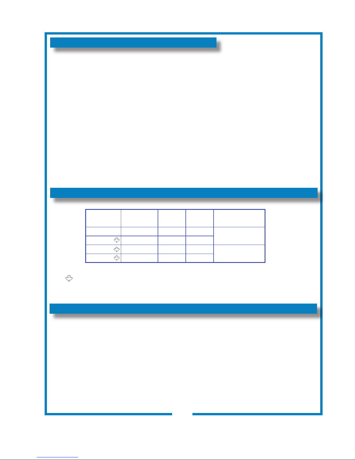
TABLE OF CONTENTS
WARRANTY STATEMENT xi
SPECIFICATIONS 1
FEATURES & OPERATING CONTROLS 2
PRECAUTIONS & GENERAL INFORMATION 3
AGENCY LISTING INFORMATION 3
INSTALLATION INSTRUCTIONS 4
OPERATION 6
CLEANING INSTRUCTIONS 7
TROUBLESHOOTING SUGGESTIONS 8
SERVICING INSTRUCTIONS 9
Deliming Instructions 12
EXPLODED VIEW & PARTS LIST 13
WIRING DIAGRAMS 16
SPECIFICATIONS
MODEL
1222 120 1800 15
1222CA 120 1500 12.8
1225 208 4000 19
1226 240 4000 16.5
VOLTS
1ø 50/60Hz 1ø
WATTS
AMPS
Thank You for purchasing this
Wells Bloomeld appliance.
Proper installation, professional
operation and consistent
maintenance of this appliance will
ensure that it gives you the very
best performance and a long,
economical service life.
This manual contains the
information needed to properly
install this appliance, and to use,
care for and maintain or repair the
appliance in a manner which will
ensure its optimum performance.
POWER SUPPLY
CORD
NEMA 5-15P
NEMA 6-30P
Meets Canadian standards
APPLICABILITY
This manual applies to the following Wells Bloomeld products:
1222 2-Gallon Hot Water Dispenser
1222CA 2-Gallon Hot Water Dispenser
1225 5-Gallon Hot Water Dispenser
1226 5-Gallon Hot Water Dispenser
712 p/n 2M-76580 1222_1225_1226 Owmers Manual
1
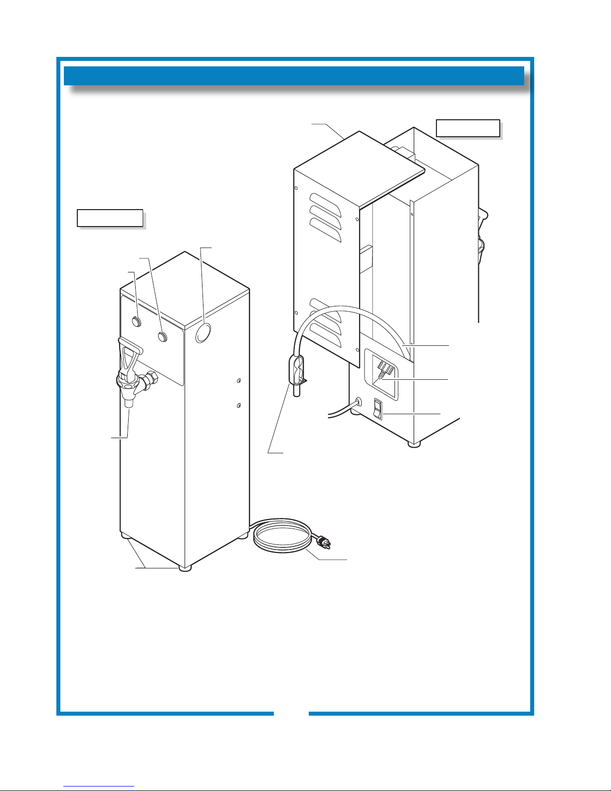
FEATURES AND OPERATING CONTROLS
HOT
WATER
REAR COVER
FLEXIBLE
DRAIN LINE
WATER SUPPLY
CONNECTION
TANK HEATER
SWITCH
POWER LITE
READY LITE
DISPENSE
FAUCET
RUBBER
GRIP FEET
POWER CORD
THERMOSTAT
ACCESS
FRONT VIEW
REAR VIEW
DRAIN LINE
TUBING CLAMP
IL2081
2
712 p/n 2M-76580 1222_1225_1226 Owmers Manual
PRECAUTIONS AND GENERAL INFORMATION
E9253
E9253
WARNING: ELECTRIC SHOCK HAZARD
All servicing requiring access to non-insulated components must be performed by qualied
service personnel. Do not open any access panels which require the use of tools.
Failure to heed this warning can result in electrical shock.
WARNING: INJURY HAZARD
All installation procedures must be performed by qualied personnel with full knowledge of all
applicable electrical and plumbing codes. Failure could result in property damage and
personal injury.
WARNING: ELECTRIC SHOCK HAZARD
Hot Water Dispenser must be properly grounded to prevent possible shock hazard.
DO NOT assume a plumbing line will provide such a ground. Electrical shock will cause death
or serious Injury.
WARNING: BURN HAZARD
This appliance dispenses very hot liquid. Serious bodily injury from scalding can occur from
contact with dispensed liquids.
This appliance is intended for commercial use only.
This appliance is intended for use to dispense heated
water. No other use is recommended or authorized by the
manufacturer or its agents.
This appliance is intended for use in commercial establishments,
where all operators are familiar with the appliance use,
limitations and associated hazards. Operating instructions and
warnings must be read and understood by all operators and
users.
Except as noted, this piece of equipment is made in the USA
and has American sizes on hardware. All metric conversions are
approximate and can vary in size.
The following trouble shooting, component views and parts lists
are included for general reference, and are intended for use by
qualied service personnel.
This manual should be considered a permanent part of this
appliance. The manual must remain with the appliance if it is
sold or moved to another location.
AGENCY LISTING INFORMATION
CAUTION:
EQUIPMENT DAMAGE
DO NOT plug in or energize this
appliance until all Installation
Instructions are read and followed.
Damage to the dispenser will
occur if these instructions are not
followed.
CAUTION:
BURN HAZARD
Dispensed liquid is VERY HOT
and can cause burns.
CAUTION:
BURN HAZARD
Exposed surfaces of the
appliance may be HOT to the
touch and can cause burns.
This dispenser is and listed under le E9253.
This dispenser meets
operated and maintained in accordance with the enclosed
instructions.
712 p/n 2M-76580 1222_1225_1226 Owmers Manual
Standard 4 only when installed,
STANDARD 4
3
INSTALLATION
READ THIS CAREFULLY BEFORE STARTING THE INSTALLATION
IMPORTANT:
To enable the installer to make
a quality installation and to
minimize installation time, the
following suggestions and tests
should be done before the
actual unit installation is started:
CAUTION:
EQUIPMENT DAMAGE
DO NOT plug in or energize this
appliance until all Installation
Instructions are read and
followed. Damage to the
dispenser will occur if these
instructions are not followed.
CAUTION:
UNSTABLE
EQUIPMENT HAZARD
It is very important for safety
and for proper operation that
the dispenser is level and
stable when standing in its nal
operating position. Provided
adjustable, non-skid legs must
be installed at each corner
of the unit. Failure to do so
will result in movement of the
dispenser which can cause
personal Injury and/or damage
to appliance.
NOTE: Water supply inlet line
must meet certain minimum
criteria to insure successful
operation of the dispenser.
Bloomeld recommends 1/4”
copper tubing for installation of
less than 12 feet and 3/8” for
more than 12 feet from a 1/2”
water supply line.
REFER TO EXPLODED VIEWS PAGE 14 FOR COMPONENT
NAMES/NUMBERS.
Unpack the unit. Inspect all components for completeness and
condition. Ensure that all packing materials have been removed
from the unit.
LEVELING THE UNIT
Two Gallon Dispenser is NOT provided with adjustable legs. Be
sure dispenser is placed on a solid level surface with all four feet
touching the surface.
Five Gallon Dispenser is provided with adjustable legs. Verify
that an adjustable leg is installed at each corner of the brewer.
Set Brewer in its operating location. Level the Brewer. A spirit
level should be placed on the top of the unit, at the edge, as a
guide when making level adjustments. Level the unit from left to
right and front to back by turning the adjustable feet. Be sure all
four feet touch the counter to prevent tipping.
PLUMBER’S INSTALLATION INSTRUCTIONS
Dispenser should be connected to a POTABLE WATER, COLD
WATER line. Flush water line before connecting to appliance.
DO NOT use a saddle valve with a self-piercing tap for the water
line connection. Such a tap can become restricted by waterline
debris. For systems that must use a saddle tap,
main water supply and drill a 3/16” (minimum) tap for the saddle
connection, in order to insure an ample water supply. Remember
to ush the line prior to installing the saddle.
The dispenser must be installed on a water line with average
pressure between 20 PSI and 90 PSI. If your water pressure
exceeds 90 PSI at anytime, a pressure regulator must be
installed in the water supply line to limit the pressure to not more
than 90 PSI in order to avoid damage to lines and solenoid.
A water shut-off valve should be installed on the incoming water
line in a convenient location (Use a low restriction type valve,
such as a 1/4-turn ball valve, to avoid loss of water ow thru the
valve.
shut off the
4
712 p/n 2M-76580 1222_1225_1226 Owmers Manual
 Loading...