

Page 1

DoPLnoInduction
Touch Control
Domino Induktion
Sensorstaten
MIS 3200 X
,QVWUXFWLRQV0DQXDOV
*HEUDXFKVDQOHLWXQJ
*% FR DE
PT FL
DA
Page 2

Page 3
ENGLISH
DOMINO INDUCTION
TOUCH CONTROL
OPERATING INSTRUCTIONS BOOK
GB
Page 4

Page 5

CONTENTS
1. WARNINGS……………………………………………………… 3
1.1 For installation……………………………………………….. 3
1.2 For cooking…………………………………………………… 3
2. INSTALLATION……………… ………… ………… ………… …. 5
2.1 Instruction for the installer…………………………………… 5
2.2 Instruction for the user……………………………………..... 6
2.3 Key panels…………………………………………………..... 8
3. FUNCTIONS
……………………………………………………... 9
3.1 ON/OFF switching of cooking zone …………………...…... 9
3.2 Cooking levels ……………………………………………..…10
3.3 Residual heat indication ………………………………….… 10
3.4 Key lock………………….………………………………….….10
3.5 Break indication …………………………………………….…10
3.6
Timer function ……………………………………………….11
3.7 Lo Temp – function (presently only for induction)………… 11
3.8 Booster……………………………………..………………..... 11
3.9 General errors …………………………………….………… 12
4. TECHNICAL DATA……………………………………………. 14
1
Page 6

2
Page 7

1.WARNINGS
Read these instructions for use carefully. This is the only way to use the hob correctly
and safely.
Keep the assembly instructions, the instructions for use and the technical data sheet
for the appliance in a safe place.
Check the hob immediately after unpacking it. If any damage has been caused during
transport, do not connect the appliance.
1.1 Important for installation
Connections must only be made by authorized and qualified personnel. If there
is any damage due to incorrect connections, any type of guarantee will no
longer be valid.
The electrical system must be equipped with an appropriate earth connection
system.
The material and glues used for the kitchen unit must resist a temperature of
min.100°C.
WARNING
Before any operation:
Disconnect the hob from the electrical mains.
Make sure that the hob is cold.
Do not try to repair the hob on your own, contact a qualified service centre.
1.2 For cooking
This appliance has been specifically designed for domestic use. The hob must only
be used for preparing food dishes.
Do not touch cooking zones that are overheated. BURN HAZARD!!! Keep out of
children’s reach. The afterheat indicator warns if zones are overheated.
Never place inflammable objects on the hob. FIRE HAZARD!!!
The power supply cable for electrical appliances must never touch hot cooking zones.
Cable insulation and the hob might get damaged.
The cooking zone and pan bottom must always be dry.
3
Page 8

If there are breaks, cracks or splits in the ceramic glass, there is a risk of shortcircuiting. Immediately switch off the appliance. Contact the technical assistance
service.
If the hob switches off by itself and it cannot be used, it is necessary to disconnect it
immediately from the electrical system and contact the technical assistance service.
Any repair operations carried out incorrectly are a high risk. Risk of electric
shocks!!! Repairs must only be carried out by qualified and specialized technical
personnel.
Rough surfaces on pans and frying pans scratch ceramic glass. Check pans.
For special pans, follow the manufacturer’s instructions.
Never place hot pans or frying pans on the control panel, on the display area or the
frame. This might cause damage!!!
Salt, sugar and sand scratch ceramic glass. Do not use the hob as a work surface or
for placing anything.
Hard or pointed objects accidentally falling on the hob may cause damage. Do not
place these objects on the hob.
Sugar and other food with high sugar content will damage the hob. Any spilt food
must be removed immediately with a scraper for glass.
Warning!!! The scraper
for glass has a sharp blade. (OPTIONAL fig. 6 )
The following damage will not affect the correct functioning or the stability of
the ceramic glass.
• The formation of gelatinous residues due to melted sugar or food with a high
sugar content.
• Scratches due to salt, sugar or sand grains or rough pan bottoms.
• Metal colour from pan use or after using unsuitable detergents.
• Opaque decoration after using unsuitable detergents.
Only use warm water with an alkaline product. Do not use corrosive or abrasive
products, as they might cause the formation of opaque areas.
4
Page 9

2.INSTALLATION
All operations relative to installation ( electric connection ) should be carried out by
personnel in conformity with the rules in force,
As for the specific instructions, see part pertaining to the installer,
2.1 Instructions for the installer ( fig. 4 )
The present instructions are turned to the skilled installer as a guide to installation,
regulation and maintenance in compliance with the laws and the rules in force.
Should a build-in oven or any other appliance producing heat be fitted directly
under a glass ceramic cook-top with TOUCH CONTROL, THE APPLIANCE
(oven) AND THE GLASS CERAMIC COOK.TOP MUST BE PROPERLY
INSULATED, so that the heat produced by the oven, measured on the right side
of the bottom of the cook-top, is lower than 60°c. Disregard of the precaution
could cause the working of the TOUCH CONTROL system.
The appliance is provided to be built in a work-top as shown the relative figure
4. When there is accessible cupboard space underneath the cook top, a
partition made of insulating material (wood or the like) must be inserted
between the cook top and the space below. This partition must be at least 10
mm from the underside of the cook top tray.
Positioning
Spread the sealing agent all the perimeter. (for cut dimensions, see fig. 2)
Lock the appliance on the work-top with brackets, taking into consideration the
thickness of the work-top (fig. 1).
Electrical connections ( fig. 3 )
Before carrying out any electrical connection, be sure that;
- the characteristics of the electrical system meet the specifications of the plate
located at the bottom of the work-top;
- the electrical system is provided with effective ground in compliance with the
rules and the provisions of the law in force.
The ground is binding according to the law.
If you wish a direct connection to the line, it is necessary to interpose a single-pole
switch, with a minimum opening between the contacts of 3mm, suitable for the load
indicated in the plate and in conformity with the rules in force ( the yellow/green
ground cable should not be interrupted by the switch).
The single-pole switch should be easily accessible with appliance installed.
Note: The manufacturer declines all responsibility if the above and the usual
safety rules are not followed.
5
Page 10
2.2 Instructions for the user
Receptables ( fig. 5)
We suggest receptacles with a flat bottom, having same or slightly higher diameter
than the one of the heating area.
Receptacles should not have rough bottoms in order to avoid scratches on the
heating surface.
Use only saucepans and frying pans with a sturdy, preferably thick bottom. This is
particularly important when preparing food requiring high cooking temperatures, such
as fried foods. If the bottom of the pan is not perfectly flat, the food takes loger to
cook and uses up more energy. The best heat transfer is obtained when the
saucepan and burner are the same size.
The induction cooking method rapidly transfers the energy needed for cooking directly
to the pan, so the cook top surface remains cold but the pan heats up. The result is a
fast, cost-effective and accurate cooking method. This type of cook top can be used
with enamelled steel or stainless steel pans; it is not suitable for use with glass,
ceramic or aluminium pans( unless a special magnetic base plate is used.
Limits of pot detection function
The following table shows the limits of the pot detection as they are tested
with cast iron
Nominal diameter of coil Limit of pot detection
(switches ON)
Ø 145 mm
Ø 90 mm
Ø 210 mm
Ø 135 mm
Integrated pot detection
Each one the cooking zones is equipped with a pot detection function. The pot
detection prevents a cooking zone from turning on without a pot being put on it. And
the cooking zone turns off as soon as the pot is taken away from it. The cooking zone
is turned off automatically after a certain time when a cooking level is set but there is
no pot put on it.
The pot needs to be made of magnetisable material. The pot detection of the
induction module depends on the pot and the material it is made of.
6
Page 11

IMPORTANT
Ƈ Avoid overflows of liquid, therefore when to boil or heat liquid, reduce the
heating supply;
Ƈ at the end of cooking, take again the cooking surface, disconnect the electric
power supply immediately.
If you find even a slight break on the cooking surface, disconnect the electric power
supply immediately.
Manteinance
First of all remove leftovers and grease from the cooking surface with the special
scraper ( optional, fig. 5).
After that clean the heating area as best as possible with a paper towel and SIDOL,
STAHLFIX or other similar products, then rinse again with water and dry with a clean
cloth.
Pieces of aluminium paper and plastic material which have unintentionally melted,
sugar or highly sacchariferous leftovers must be removed immediately from the
cooking area with the special scraper (optional, fig. 5) to avoid any possible damage
to the surface of the cook-top.
Never use abrasive sponges or irritating chemical detergents such as oven sprays or
spot removers.
Protection against excess temperature
The generator as well as the coils have integrated functions protecting against excess
temperature.
Inside the power board a temperature sensor controls the temperature of the heat
sink to protect the devices.
Soiling on the glass ceramic surface
Soiling, normally food stuffs and/or water can – however, not necessarily –
be mistaken as a key touch. Also, dampness in thin layers (film, streaks) may
cause this effect. Especially with larger quantities there is a chance that
none, one, several or all keys can, thus, be mistaken as touched briefly or
permanently. In this respect, soiling can, for a short period, lead to alterations
of settings which can just as well be generated by an operator. In case of
such an alteration e. g. activation of a cooking zone, the entire Touch Control
is disconnected after max. 10 sec (due to permanent operation detection).
This implies that the „activating“ effect on the sensors
caused by the soiling remains basically unchanged for as long as 10 sec.
7
Page 12
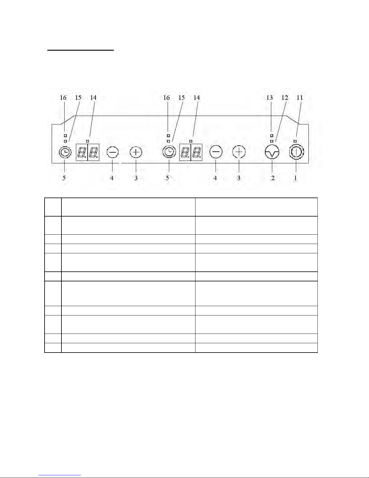
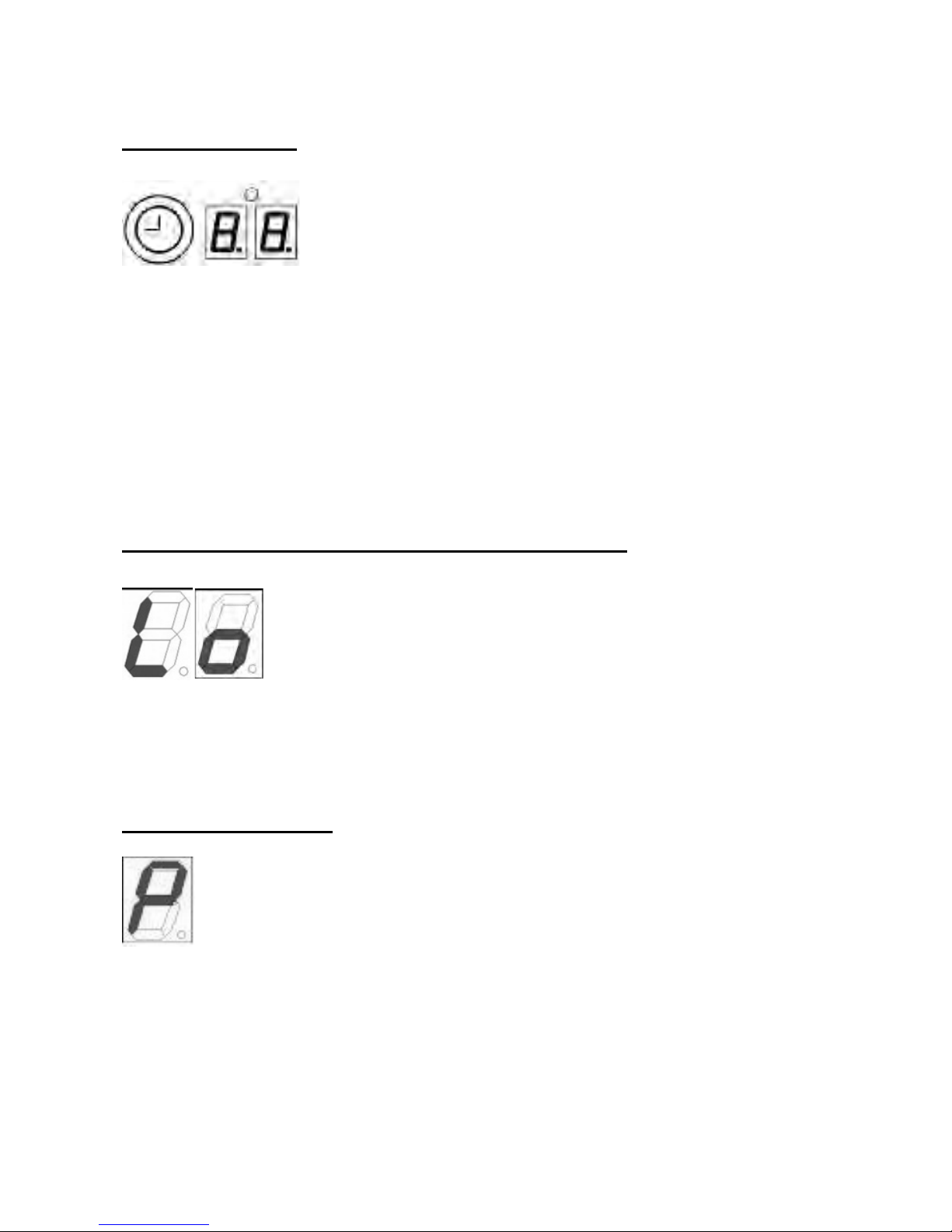
2.3 KEY PANEL:
Overview and description
Picture 1: Touch Domino incl. all keys, displays and LEDs
1 ON/OFF switch press for 1sec to switch control
unit ON/OFF
2 Multi-circuit / Special key e.g. key lock, break, dual-circuit,
triple-circuit
3 Plus increase cooking level
4 Minus reduce cooking level
5 Timer / Cooking zone special
function
Timer, dual-circuit, triple-circuit (if
no timer available)
11 Power LED
12 LED general special function 1 Cooking zone locked, dual-circuit
13 LED general special function 2 Triple-circuit
14 Timer LED Programming timer or cooking
level
15 LED Cooking zone special fct. 1 Cooking zone locked, dual-circuit
16 LED Cooking zone special fct. 2 Triple-circuit
8
Page 13

3.FUNCTIONS
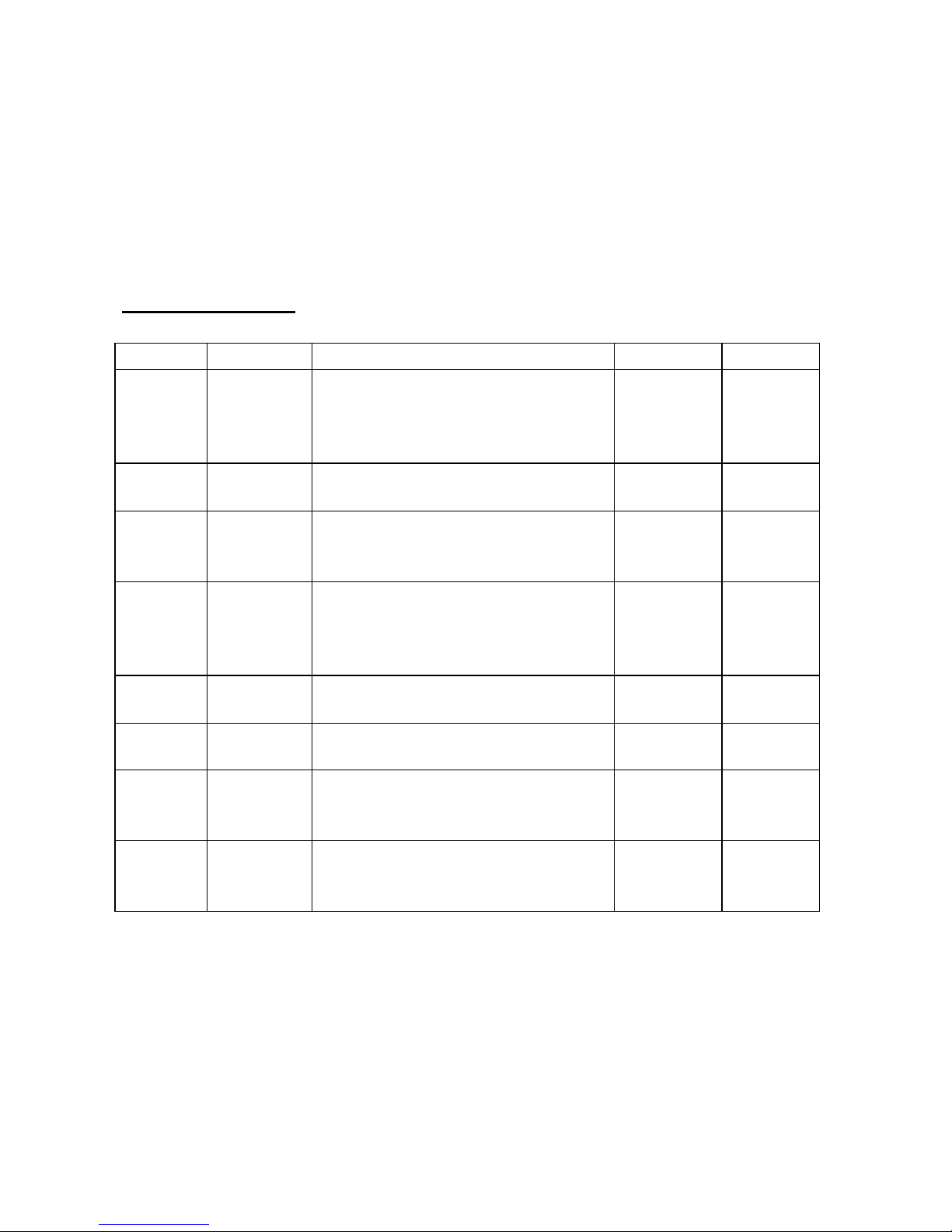
3.1 ON/OFF switching of cooking zone
By pressing the ON/OFF key for 1 sec (key no. 1) the Touch Control changes
from OFF mode into standby mode emitting a short buzzing signal as well as
a visible „0“ on the cooking zone display. Instead of „0“ the cooking zone
display can also show an „H“ meaning „hot cooking surface” or, alternatively,
an „E“ meaning “error”. If no key is touched within the 10 sec after activating
the standby mode, the Touch Control unit changes back into OFF mode.
While activated or in standby mode the electronics may be reset, at any time,
into OFF mode by simply touching the ON/OFF key. During operation, the
OFF function always has priority , i. e. even if several keys are touched
simultaneously, the control unit would switch off. The Touch Control unit can
still be switched off, even though the Key-Lock function (see 2.10) had been
activated.
ON/OFF switching of a cooking zone
ON switching
A cooking zone can be directly activated via the corresponding plus / minus
keys while in standby or active mode, unless the cooking zone had not been
set by the optional timer programming (see 2.13).
Starting position: Cooking zone is in OFF mode. Display: „0“: If starting
out with the „+“ key, the cooking stage display moves from „0“ up to „5“. If
starting out with the „-“ key, the cooking stage display moves from „0“ up
to „9“ (i. e. the highest configurated cooking stage available).
While pressing the „+“ or „-“ key, the cooking stage is increased /
reduced automatically. The time difference occurring during changing
from one stage to another is about 0.5 sec. The buzzer only emits an
audible signal at the first change of cooking stages. Once the highest or
lowest stage is reached, the cooking stage remains there (limit stop).
Only releasing the key and touching again results in skipping this limit
stop. („0“ Å „9“ or „9“ Å „A“). Even if no automatic heat-up function or
booster function is available for the relevant cooking zone, changing from
9 to 0 is not possible.
OFF switching
A cooking zone can be switched off in the following way:
by pressing the „+“ and the „-“ keys of the desired cooking zone
simultaneously
by selecting cooking zone „0“ for the desired cooking zone by pressing
the „-“ key.
9
Page 14
3.2 Cooking levels
As a standard, there are 9 cooking levels with the digits „1“ to „9“ on the
display.
„A“ for automatic heat-up function, „P“ for booster or the symbol for „no pot”
are only displayed on the right or on the single display serving a cooking
zone
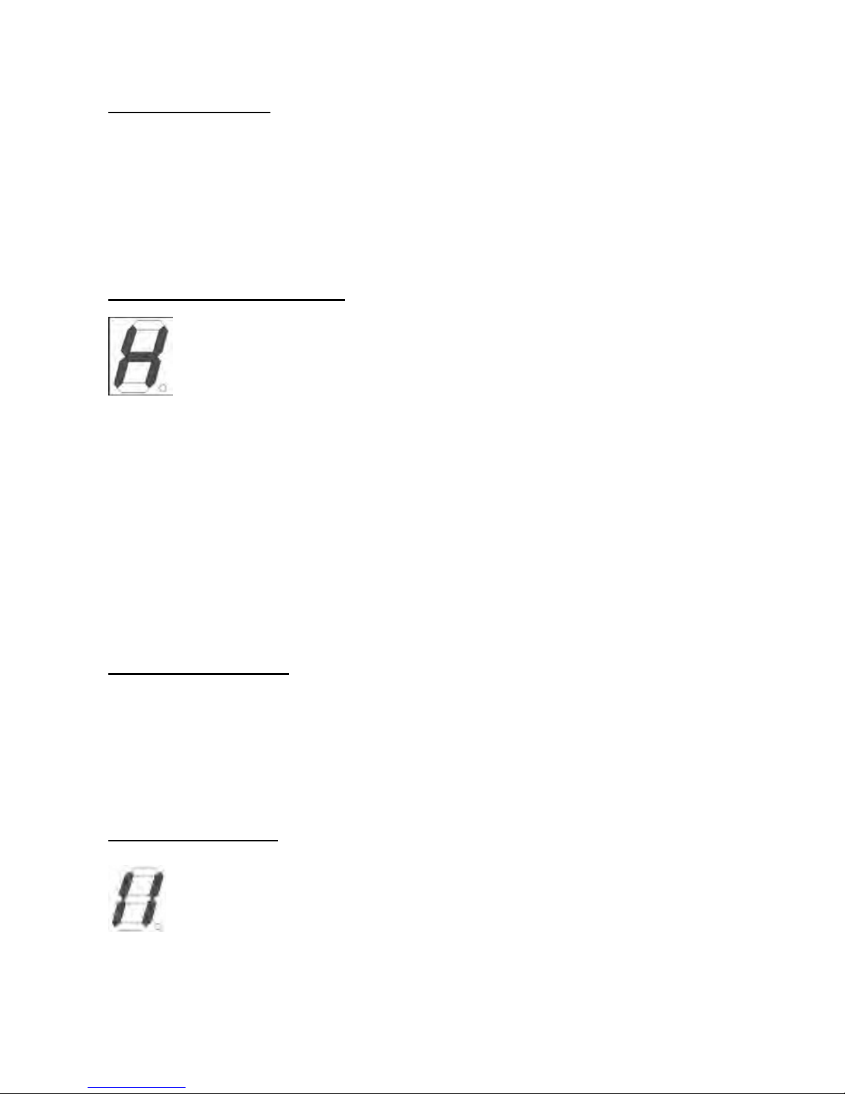
3.3 Residual heat indication
A hot cooking zone is indicated by an „H“
Overheat control for induction cooking zones
In principle, the induction works intrinsically safe.
The induction electronics provide temperature sensors at each cooking zone
being located
below the glass ceramic surface to monitor temperatures. Further
temperature sensors along
the heat sink protect the electronics itself against overheating.
This causes the „P“ symbol to flash on the relevant display indicating that the
booster request cannot be dealt with currently.
3.4 Key-lock function
LED 12 serves as display of the key-lock status. In this case locking and
unlocking can be done by pressing the minus key and the special function
key (key no.2 ) of a cooking zone at the same time. This also works for
locking at one cooking zone and unlocking at another and vice versa.
Switching OFF via the ON/OFF key is also possible in locked conditions.
3.5 Break indication
While at least one cooking zone is working, the cooking zones can
be switched off by touching the general special key (key no. 2) for
more than 1 sec.
The break mode can last for max. 10 min.
10
Page 15
3.6 Timer function
The timer function module provides a timer for each of
both cooking zones of a Touch Control.
All timers are countdown timers. The optional setting range is between 1 and
99 minutes. After the timer is set, it counts backwards in minute steps down
to 0. Then, a visible and audible alarm signal is emitted.
As for a cooking zone related mode, the corresponding cooking zone is
disconnected automatically upon expiry of the timer.
Before operating a timer, the Touch Control is to be switched into at least
standby mode via the ON/OFF key. Switching off the Touch Control disables
the cooking zone related timer, programmed egg timers continue running.
3.7 Lo Temp – function (presently only for induction)
The Lo Temp function is supposed to keep cooked meals
warm on top of a cooking zone.
The operator can activate it by selecting a cooking stage
between 0 and 1 resulting in both cooking zone displays to show the symbol
„Lo“ (see above). If the cooking stages are reduced by holding the minus
key, the Low-temp cooking stage is stopped. Another touch would be
necessary to switch to stage 0.
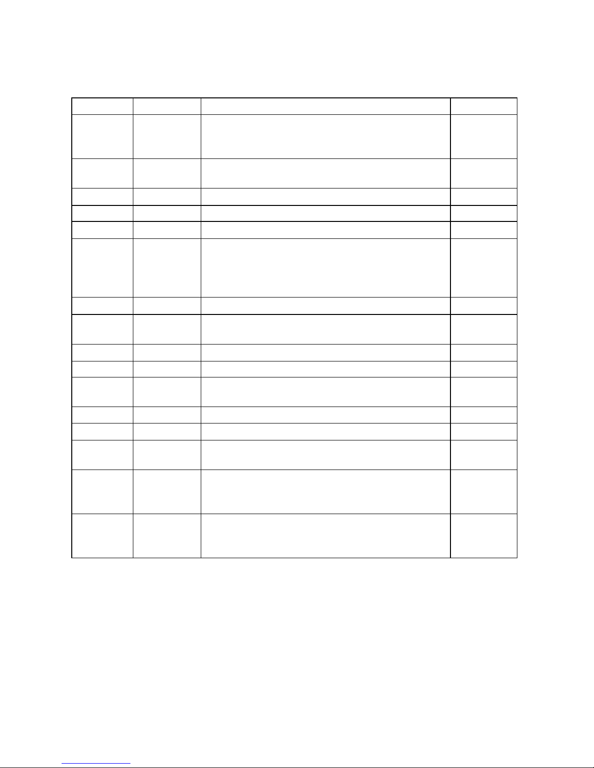
3.8 Booster activation
All induction cooking zones have a booster function.
The booster allows a particularly speedy heating of the food stuffs,
thus, helping the operator to save time.
No booster key available in the system:
Cooking zone must be set to the highest possible level :
Release of „+“ or „-“ key. Another touch on the „+“ key activates the booster
function. The corresponding cooking stage display shows a static „P“ symbol.
11
Page 16
For safety reasons the booster function of each cooking zone is only
available for a limited period of 10 min.
Pressing the minus key while the booster function is activated results in
disconnecting the same. Pressing the „+“ key has no effect on it.
The max. permissible output per induction power board is 3700 W.
3.9 General errors
Priority Display Description Lag-time System
1 U400 Blind connection of control.
Directly located at radiant
heating element or reported via
LIN (induction)
1 sec all
2 Er31 Invalid or no configuration
available
1 sec induction
3 Er47 Interference on LIN Bus. A
necessary participant
does not respond
1 sec induction
4 Er36 Short-circuit of temperature
sensor of TC(all) or of
power board (only rad. heat.
element)
10 sec all
5 Er39 Wrong programming options
(fuses, lockbits)
1 sec all
6 Er20 Defective controller flash.
Checking total incorrect
1 sec all
7 Er37 Faulty feedback of shift register
signals to the
segment or relay activation
1 sec all
8 Er22 Faulty keyboard: at least one
key has invalid
level
10 sec all
12
Page 17
Cooking zone specific errors
Priority Display Description System
1 E5 LIN Bus communication error. Most
probably diagnosed by the Touch
Control unit and indicated as Er47
Induction
2 E5 Defective controller flash. Incorrect
checking total
Induction
3 E5 Wrong programming options Induction
4 E5 Incorrect EEPROM checking total Induction
5 E5 Unclear EEPROM data Induction
6 U400 Overvoltage 400V (becomes general error
with Touch Control as
soon as indicated by at least one induction
cooking zone)
Induction
7 E5 Error mains voltage signal Induction
8 E7 Sub LIN error between filter and power
board
Induction
9 E6 5V short circuit with power board Induction
10 E6 12V too low for power board Induction
11 E6 Defective temperature sensor on cooling
element
Induction
12 E6 Faulty mains hold pulse Induction
13 E9 Defective coil detector Induction
14 E2 Overheated coil detector (diagnosed by
induction)
Induction
15 „Blitz“ Permanent operation (minim. 10 sec) upon
switching a cooking zone
off
all
16 „Blitz“ Permanent operation (minim. 10 sec)
without switching a
cooking zone off
all
13
Page 18
E2 Overheating
E5 Exchange filter board
E6 Exchange power board
E7 Unknown error, cannot be clearly identified
E9 Exchange temperature sensor
4 Technical data
Rated voltage and current
nominal voltage: 220-240 V
nominal frequency: 50-60 Hz
The power of a power board is limited to 3700 W.
Use only rubber cable type H05VV-F; the cross-setion on the wires must be
3x1.5mm.
Stand-by consumption of the generator
Max. 0,6 W (not including user interface).
Nominal power and diameters of coils
Diameter Nominal power Boost power
Ø 145 mm
1400 W 1800 W
Ø 210 mm
2300 W 3200 W
diameter nominal power boost power
14
Page 19

Fan control
Integrated cooling of the generator
The cooling is integrated within the plastic housing of the generator. The
operation of the fan is controlled by the temperature which is measured at
the heat sink. Then fan switches on, when a certain temperature is reached
and switches to a higher speed when the second temperature limit is
reached.
Start lower speed 45°C
Start higher speed 55°C
Temperature control of cooking zones
The residual heat indicator contributes to the protection of the user. The
residual heat indication switches on with an „H“ as soon as a certain
temperature underneath the glass ceramic is reached.
And it switches off again as soon as the temperature decreases under a
certain level.
Threshold „ON“ residual heat indicator 65°C + 5K
Threshold „OFF“ residual heat indicator 60°C – 5K
15
Page 20
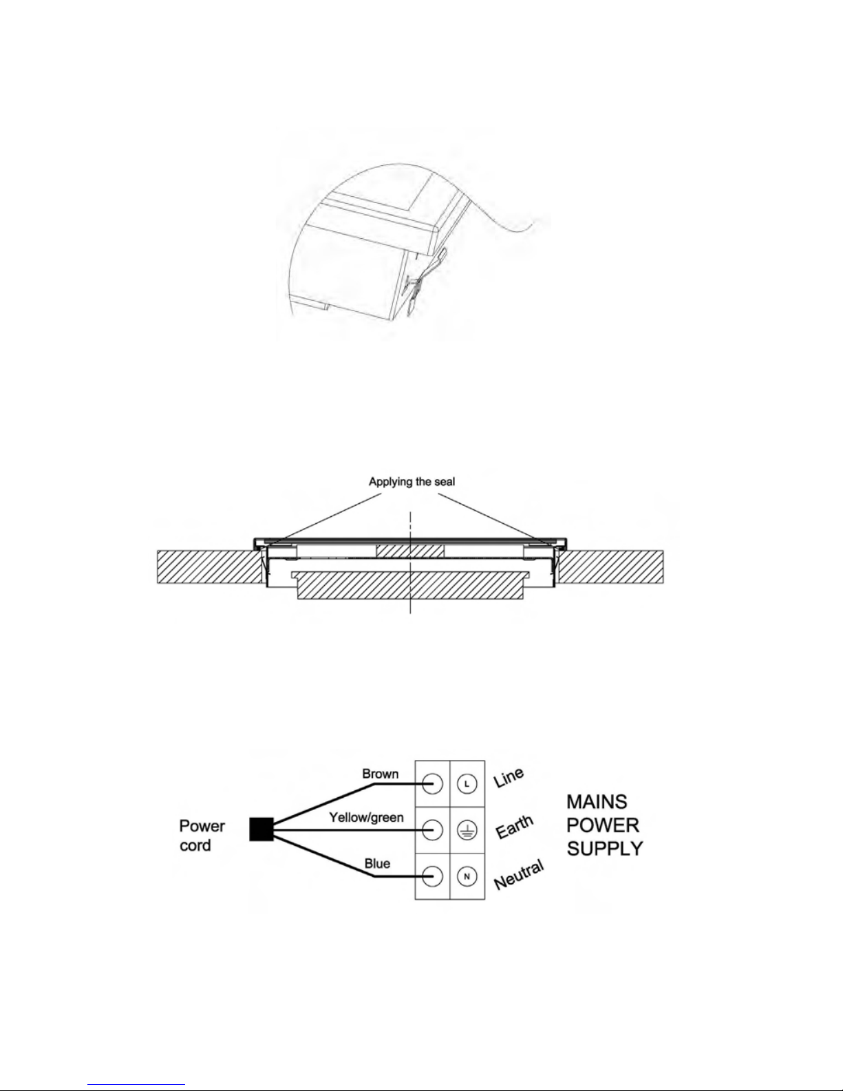
Fig.1
Fig.2
Fig.3
16
Page 21
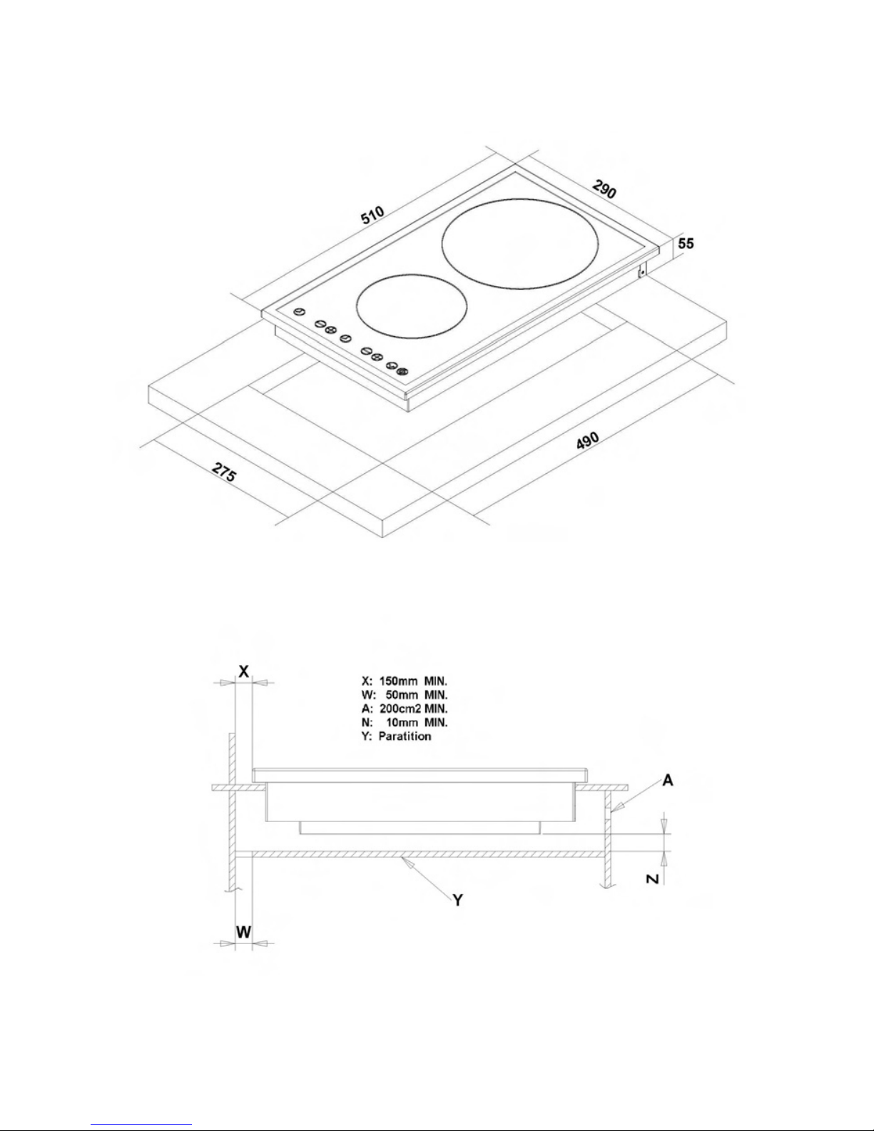
Fig.4
17
Page 22
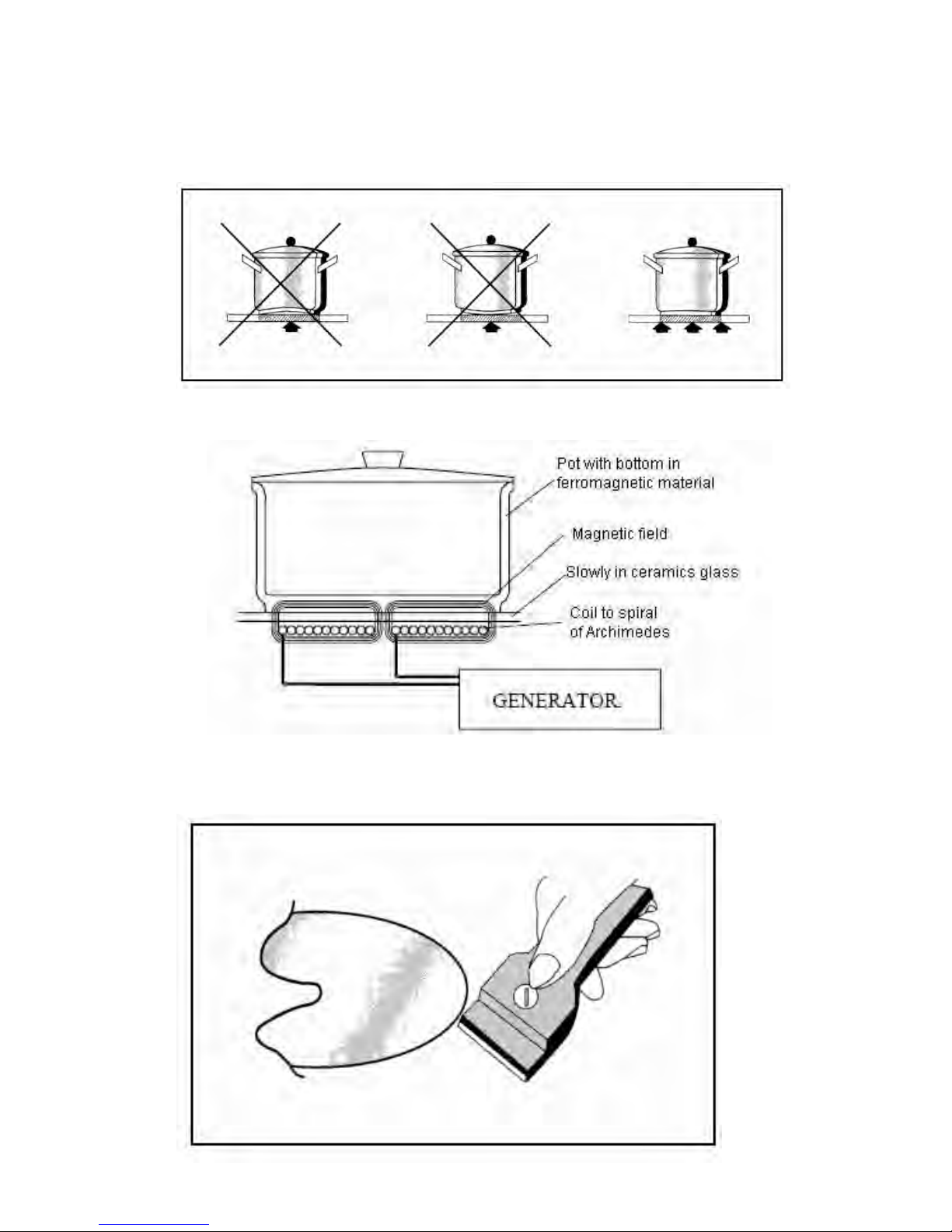
Fig.5
Fig.6
18
Page 23

FRANÇAIS
DOMINO INDUCTION
COMMANDE SENSITIVE
MANUEL D’UTILISATION
F
R
Page 24

Page 25

TABLE DES MATIÈRES
1. AVERTISSEMENTS……………………………………………………… 23
1.1 Pour l’installation……………………………………………….. 23
1.2 Pour la cuisson…………………………………………………… 23
2. INSTALLATION…………………………………………………... 25
2.1Instructions pour l'installateur…………………………………… 25
2.2Instructions pour l’utilisateur…………………………………… 26
2.3Bandeau de commande……………………………………………..... 29
3. FONCTIONS……………………………………………….……... 30
3.1Commande Marche/Arrêt de la zone de cuisson ………………...... 30
3.2 Niveaux de cuisson …………………………………………….......… 31
3.3 Indication de chaleur résiduelle …………………………………..… 31
3.4 Verrouillage des touches………………….………………………..…. 31
3.5 Indication de pause ………………………………....................….… 32
3.6
Fonction minuterie ………………………………………….....……. 32
3.7 Fonction Basse temp. (disponible uniquement pour l'induction).... 32
3.8Fonction d’appoint……………………………………......................... 33
3.9 Erreurs générales …………………………………….…………........ 33
4. DONNÉES TECHNIQUES…………………………………………….... 36
21
Page 26

22
Page 27

1.AVERTISSEMENTS
Veuillez lire ces instructions d’utilisation attentivement. Il s’agit de la seule façon
d’utiliser la table de cuisson correctement et en toute sécurité.
Conserver soigneusement les instructions de montage, les instructions d’utilisation et
la fiche technique de l'appareil.
Inspecter la table de cuisson immédiatement après l'avoir déballée. Si des
dommages ont été occasionnés durant le transport, ne pas connecter l’appareil.
1.1 Important pour l’installation
Les raccordements doivent uniquement être effectués par le personnel agréé et
qualifié. En cas de dommages dus à des raccordements inadaptés, tout type de
garantie ne sera plus valable.
Le système électrique doit être muni d’un système d’installation électrique
adapté de mise à la terre.
Les matériaux et colles utilisées pour l’élément de cuisine doivent résister à
une température minimale de 100 °C.
AVERTISSEMENT
Avant toute utilisation :
Déconnecter la table de cuisson du réseau d'alimentation électrique.
S’assurer que la table de cuisson est froide.
Ne pas essayer de réparer la table de cuisson par vous-même ; contacter un
centre de service qualifié.
1.2 Pour la cuisson
Cet appareil a été conçu spécifiquement pour l'usage domestique. La table de
cuisson doit uniquement servir à préparer des denrées alimentaires.
Ne pas toucher les zones de cuisson surchauffées. RISQUE DE BRÛLURE !!! Tenir
hors de la portée des enfants. L’indicateur de chaleur résiduelle indique si les zones
sont surchauffées.
Ne jamais poser d’objets inflammables sur la table de cuisson. RISQUE D’INCENDIE
!!!
23
Page 28

Le câble d’alimentation des appareils électriques ne doit jamais entrer en contact
avec les zones de cuisson chaudes. L’isolation du câble et la table de cuisson
pourraient être abîmés.
La zone de cuisson et le bas des récipients doivent toujours être secs.
Si vous observez des cassures, fêlures ou fissures sur la surface vitrocéramique, il y
a un risque de court-circuit. Éteindre l’appareil immédiatement. Contacter le service
d’assistance technique.
Si la table de cuisson s'éteint par elle-même et ne peut être utilisée, il convient de la
déconnecter du système électrique immédiatement et de contacter le service
d’assistance technique.
Toutes réparations réalisées incorrectement présentent un risque important. Risque
de décharges électriques !!! Les réparations sont réservées au personnel technique
qualifié et spécialisé.
Les surfaces rugueuses sur les casseroles et poêles rayent la surface céramique.
Inspecter les récipients.
Pour les récipients spéciaux, suivre les instructions du fabricant.
Ne jamais poser de casseroles ou poêles chaudes sur le bandeau de commande, la
zone d'affichage ou le cadre. Ceci pourrait occasionner des dommages !!!
Le sel, le sucre et le sable rayent la surface céramique. Ne pas utiliser la table de
cuisson comme surface de travail ou de rangement.
Les objets durs ou pointus qui pourraient tomber sur la table de cuisson par accident
pourraient occasionner des dommages. Ne jamais poser de tels objets sur la table de
cuisson.
Le sucre et autres aliments à forte teneur en sucre abîmeront la table de cuisson.
Tout déversement de nourriture doit être nettoyé immédiatement à l’aide d'un grattoir
pour verre.
Avertissement !!! Le grattoir pour verre est muni d’une lame
affûtée. (EN OPTION fig. 6)
Les dommages suivants n’auront aucun effet sur le bon fonctionnement ou la
stabilité de la surface vitrocéramique.
• La formation de résidus gélatineux due à du sucre fondu ou des aliments à
forte teneur en sucre.
• Rayures dues aux grains de sel, sucre ou sable ou aux fonds rugueux des
récipients.
• Couleur métallique due à l’utilisation de récipients ou suite à l’emploi de
détergents inadaptés.
• Décoloration opaque suite à l'utilisation de détergents inadaptés.
24
Page 29

Utiliser uniquement de l’eau chaude avec un produit alcalin. Ne pas utiliser de
produits corrosifs ou abrasifs car ils pourraient entraîner la formation de zones
opaques.
2.INSTALLATION
Toutes les opérations relatives à l’installation (raccordement électrique) doivent être
effectuées par le personnel conformément aux réglementations en vigueur.
En ce qui concerne les instructions spécifiques, voir la section destinée à
l’installateur.
2.1 Instructions pour l’installateur (fig. 4)
Les instructions ci-dessous sont adressées à l’installateur qualifié en tant que guide à
l’installation, la réglementation et la maintenance conformément aux lois et normes
en vigueur.
S’il est prévu qu’un four intégré ou un autre appareil générant de la chaleur soit
installé directement sous la plaque de cuisson vitrocéramique à COMMANDE
SENSITIVE, L'APPAREIL (four) ET LA PLAQUE DE CUISSON
VITROCÉRAMIQUE DOIVENT ÊTRE ISOLÉS CORRECTEMENT de manière à ce
que la chaleur émanant du four, mesurée sur le côté droit du dessous de la
plaque de cuisson soit inférieure à 60 °C. La négligence de cette précaution
pourrait affecter le fonctionnement du système de COMMANDE SENSITIVE.
L’appareil est conçu pour être intégré dans une plaque de cuisson comme
l’indique la figure relative numéro 4. S’il y a de l’espace dans le placard situé en
dessous de la plaque de cuisson, une cloison de matière isolante (bois ou
similaire) doit être insérée entre la plaque de cuisson et l'espace situé en
dessous. Cette cloison doit se trouver au moins 10 mm en dessous du support
de la plaque de cuisson.
Positionnement
Étaler l'agent d'étanchéité tout autour du périmètre. (pour les dimensions de découpe,
voir fig. 2)
Fixer l’appareil à la plaque de cuisson à l’aide d'attaches, en prenant l’épaisseur de la
plaque de cuisson en considération (fig. 1).
Raccordements électriques (fig. 3)
Avant d’exécuter tout raccordement électrique, s’assurer que :
25
Page 30

- les paramètres du système électrique satisfont les spécifications du support situé
en dessous de la plaque de cuisson ;
- le système électrique est fourni avec un dispositif de mise à la terre efficace
conformément aux réglementations et dispositions prévues
par la loi en
vigueur.
La mise à la terre a force obligatoire selon la loi.
Si vous souhaitez établir un raccordement direct à la ligne, il est nécessaire
d’interposer un interrupteur unipolaire avec une ouverture minimale entre les contacts
de 3 mm, adapté pour la charge indiquée sur la plaque et conforme aux
réglementations en vigueur (le câble jaune/vert de mise à la terre ne doit pas être
interrompu par l'interrupteur).
L’interrupteur unipolaire doit être facilement accessible une fois l’appareil installé.
Remarque : Le fabricant décline toute responsabilité si les instructions cidessus ainsi que les règles de sécurité conventionnelles ne sont pas
respectées.
2.2 Instructions pour l’utilisateur
Récipients (fig. 5)
Nous conseillons des récipients au fond plat dont le diamètre est identique ou
légèrement supérieur à celui de la zone chauffante.
Le fond des récipients ne doit pas être rugueux afin d'éviter de rayer la surface
chauffante.
Utiliser uniquement des casseroles et poêles dont le fond est solide et épais de
préférence. Ceci est particulièrement important lors de la préparation de denrées
nécessitant des températures de cuisson élevées, telles que les aliments frits. Si le
fond du récipient n'est pas parfaitement plat, la nourriture est plus longue à cuire et
utilise plus d'énergie. Le transfert optimal de chaleur est obtenu lorsque la casserole
et le brûleur sont de la même taille.
La méthode de cuisson par induction transfère rapidement l’énergie nécessaire à la
cuisson directement au récipient si bien que la surface de la plaque de cuisson reste
froide mais le récipient chauffe. On obtient ainsi une méthode de cuisson rapide,
rentable et précise. Ce type de plaque de cuisson est adapté à des récipients en
acier émaillé ou en inox ; il ne convient pas pour les casseroles en verre, en
céramique ou en aluminium (à moins d’utiliser un socle magnétique spécial).
Limites de la fonction de détection des récipients
Le tableau suivant indique les limites de détection des récipients lorsqu'ils
sont testés avec des ustensiles en fonte.
26
Page 31

Diamètre nominal de la bobine Limite de détection des récipients
(interrupteurs activés)
Ø 145 mm
Ø 90 mm
Ø 210 mm
Ø 135 mm
Détection intégrée des récipients
Chaque zone de cuisson est munie d’une fonction de détection des récipients. La
détection des récipients évite qu’une zone de cuisson ne se mette en marche sans
qu’un récipient soit posé dessus. De même, la zone de cuisson s’éteint dès que le
récipient est retiré. La zone de cuisson est éteinte automatiquement au bout d’un
certain temps si un niveau de cuisson est défini mais qu'il n'y a pas de récipient posé
dessus.
Le récipient doit être composé de matériaux magnétisables. La détection des
récipients du module à induction dépend du récipient et de sa matière.
IMPORTANT
Ƈ Éviter les déversements de liquides ; réduire la chaleur livrée lorsque vous
souhaitez faire bouillir ou chauffer un liquide.
Ƈ En fin de cuisson, si vous observez la moindre fissure sur la surface de
cuisson, déconnecter l’alimentation électrique immédiatement.
Entretien
Commencer par nettoyer les résidus et la graisse de la surface de cuisson à l’aide
d'un grattoir spécial (en option, fig. 5).
Ensuite, bien nettoyer la surface de cuisson avec un essuie-main en papier et du
SIDOL, STAHLFIX ou d'autres produits similaires, puis rincer à nouveau à l'eau et
sécher avec un chiffon propre.
Les morceaux de papier d’aluminium et les matières plastiques ayant été fondus
involontairement, le sucre ou les résidus saccharifères doivent être nettoyés de la
zone de cuisson immédiatement à l’aide du grattoir spécial (en option, fig. 5) afin
d’éviter tout dommage éventuel de la surface de la plaque de cuisson.
Ne jamais utiliser d’éponges abrasives ni de détergents chimiques irritants tels que
des produits de nettoyage pour les fours ou des détachants.
Protection contre les températures excessives
Le générateur ainsi que les bobines sont équipés de fonctions intégrées contre les
températures excessives.
27
Page 32

À l’intérieur de la platine d’alimentation se trouve un capteur de température qui
commande la température du dissipateur de chaleur en vue de protéger les
dispositifs.
Salissures sur la surface vitrocéramique
Les salissures, habituellement des résidus alimentaires et/ou de l’eau,
peuvent éventuellement être confondues avec une commande sensitive.
Aussi, l'humidité en couches fines (film, traînées) pourrait produire cet effet.
Pour de grandes quantités en particulier, il se peut qu'aucune, une, plusieurs
ou toutes les touches puissent donc être confondues et activées brièvement
ou de manière permanente. À cet égard, les salissures peuvent entraîner
des modifications à court terme des réglages qui pourraient aussi bien être
définis par un opérateur. Dans le cas d'une modification telle que l'activation
d'une zone de cuisson, toute la Commande sensitive est déconnectée au
bout de 10 sec au maximum (en raison de la détection permanente de
fonctionnement). Ceci implique que l’effet « d’activation » sur les capteurs
dû
aux salissures demeure fondamentalement inchangé pendant 10 secondes.
28
Page 33

2.3 BANDEAU DE COMMANDE :
Aperçu et description
Image 1 : Domino sensitif comprenant toutes les touches, écrans et voyants lumineux.
1 Interrupteur Marche/Arrêt appuyer pendant 1 sec pour
allumer ou éteindre l’unité de
commande
2 Touche multi-circuit / spéciale par ex. verrouillage des touches,
pause, double circuit, triple circuit
3 Plus augmente le niveau de cuisson
4 Moins réduit le niveau de cuisson
5 Fonction Minuterie / Zone de cuisson
spéciale
Minuterie, double circuit, triple
circuit (s'il n’y a pas de minuterie)
11 Voyant lumineux de puissance
12 Voyant lumineux, fonction spéciale
générale 1
Zone de cuisson verrouillée,
double circuit
13 Voyant lumineux, fonction spéciale
générale 2
triple circuit
14 Voyant lumineux de la minuterie Minuterie de programmation ou
niveau de cuisson
15 Voyant lumineux, fonction spéciale
zone de la cuisson spéciale 1
Zone de cuisson verrouillée,
double circuit
16 Voyant lumineux, fonction spéciale
zone de la cuisson spéciale 2
Triple circuit
29
Page 34

3. FONCTIONS
3.1 Commande Marche/Arrêt de la zone de cuisson
En appuyant sur la touche Marche/Arrêt pendant 1 sec (touche numéro 1), la
Commande sensitive passe du mode Arrêt au mode stand-by, émet un bref
bruit sourd et affiche un « 0 » sur l'écran de la zone de cuisson. Au lieu du
« 0 », la zone de cuisson peut également afficher un « H » qui signifie
« surface de cuisson chaude » ou bien un « E » pour « erreur ». Si aucune
touche n’est enfoncée au cours des 10 sec suivant l'activation du mode
stand-by, l'unité de commande sensitive passe à nouveau en mode Arrêt.
Le système électronique, lorsqu'il est activé ou en mode stand-by, peut être
réinitialisé à tout moment en passant en mode Arrêt en appuyant simplement
sur la touche Marche/Arrêt.
En cours de fonctionnement, la fonction Arrêt est toujours prioritaire, même
si plusieurs touches sont activées simultanément, et l'unité de commande
s'éteindra.
L’unité de Commande sensitive peut toujours être éteinte, même si la
fonction Verrouillage des touches (voir 2.10) a été activée.
Commande Marche/Arrêt d’une zone de cuisson
Mettre en marche
Une zone de cuisson peut être activée directement par les touches
plus/moins correspondantes en mode stand-by ou actif sauf si la zone de
cuisson n’avait pas été définie dans la programmation optionnelle de la
minuterie (voir 2.13).
Position de départ : La zone de cuisson est en mode Arrêt. Affichage :
« 0 » : En commençant par la touche « + », l'écran indiquant la phase de
cuisson va de « 0 » à « 5 ». En commençant par la touche « - », l'écran
indiquant la phase de cuisson va de « 0 » à « 9 » (c’est-à-dire la phase
de cuisson configurée la plus élevée disponible).
En appuyant sur la touche « + » ou « - », la phase de cuisson est
augmentée/diminuée automatiquement. La différence de temps entre les
passages d'une phase à une autre est d'environ 0,5 sec. La sonnerie
n’émet qu’un signal audible au premier changement de phase de
cuisson. Une fois que le niveau le plus haut ou le plus bas est atteint, la
phase de cuisson reste la même (limite atteinte). Il n’est possible de
dépasser la limite qu’en relâchant la touche puis en appuyant dessus à
nouveau. (« 0 » à « 9 » ou « 9 » à « A »). Même la zone de cuisson en
question n'est pas munie d'une fonction mise en marche automatique ou
d'appoint, il n’est pas possible de passer de 9 à 0.
30
Page 35

Éteindre
Une zone de cuisson peut être éteinte de la manière suivante :
en appuyant simultanément sur les touches « + » et « - » de la zone de
cuisson souhaitée.
en sélectionnant le niveau « 0 » pour la zone de cuisson souhaitée en
appuyant sur la touche « - ».
3.2 Niveaux de cuisson
Selon la norme, il y a 9 niveaux de cuisson numérotés de « 1 » à « 9 » à
l’écran.
Les symboles « A » pour la fonction de mise en marche automatique, « P »
pour la fonction d'appoint ou le symbole pour « pas de récipient » sont
uniquement affichés sur la droite ou sur l'écran unique correspondant à une
zone de cuisson.
3.3 Indication de chaleur résiduelle
Une zone de cuisson chaude est indiquée par un « H ».
Commande de surchauffe pour les zones de cuisson à induction
En principe, l'induction est une méthode de sécurité intrasèque.
Le système électronique comprend des capteurs de température pour
chaque zone de cuisson située
en dessous de la surface vitrocéramique afin de surveiller les températures.
D’autres capteurs de température le long
du dissipateur de chaleur protègent les composants électroniques contre la
surchauffe.
Ceci fait clignoter le symbole « P » sur l'écran correspondant et indique que
la demande d’appoint ne peut être satisfaite actuellement.
3.4 Fonction de verrouillage des touches
Le voyant 12 indique le statut du verrouillage des touches. Ainsi, le
verrouillage et déverrouillage peuvent être effectués en appuyant sur la
touche moins et la touche de fonction spéciale (touche numéro 2) d'une zone
de cuisson à la fois. La même méthode s'applique si vous souhaitez
verrouiller une zone de cuisson et en déverrouiller une autre et vice versa.
31
Page 36

Vous pouvez également éteindre au moyen de la touche Marche/Arrêt
lorsque le système est verrouillé.
3.5 Indication de pause
Pendant l’utilisation d'au moins une zone de cuisson, toutes les
zones peuvent être éteintes en activant la touche spéciale générale
(touche numéro 2) pendant plus d'une seconde.
Le mode pause peut durer 10 min maximum.
3.6 Fonction minuterie
La fonction minuterie fournit une minuterie pour
chacune des deux zones de cuisson à Commande
sensitive.
Toutes les minuteries sont des minuteries à rebours. L'intervalle de définition
optionnelle se situe entre 1 et 99 minutes. Une fois la minuterie réglée, elle
compte à rebours en minutes jusqu’à 0. Ensuite un signal visible et audible
sera émis.
En ce qui concerne le mode lié à une zone de cuisson, la zone
correspondante est automatiquement déconnectée à l'expiration de la
minuterie.
Avant d’utiliser une minuterie, il convient de faire passer la Commande
sensitive au moins en mode stand-by au moyen de la touche Marche/Arrêt.
Le fait d'éteindre la Commande sensitive désactive la minuterie liée à la zone
de cuisson, les minuteurs programmés continuant à fonctionner.
3.7 Fonction Basse temp. (disponible uniquement pour l'induction)
La fonction Basse temp. est sensée tenir les plats cuisinés
au chaud sur une zone de cuisson.
L’opérateur peut l'activer en sélectionnant une phase de
cuisson entre 0 et 1, de telle sorte que les deux écrans des zones de cuisson
afficheront le symbole « Lo » (voir ci-dessus). Si les phases de cuisson sont
32
Page 37

réduites en maintenant la touche moins enfoncée, la phase de cuisson
Basse temp. sera interrompue. Il faudrait activer une autre commande pour
passer à la phase 0.
3.8 Activation de la fonction d’appoint
Toutes les zones de cuisson à induction disposent d’une fonction
d’appoint.
Cette dernière permet de faire chauffer les denrées alimentaires
particulièrement vite, ce qui aide l'opérateur à gagner du temps.
Aucune touche d’appoint n’est disponible sur le système :
La zone de cuisson doit être réglée au niveau le plus haut possible :
relâcher la touche « + » ou « - ». Le fait d'appuyer à nouveau sur la touche
« + » active la fonction d'appoint. L’écran de la phase de cuisson
correspondant indique un symbole statique « P » .
Pour des raisons de sécurité, la fonction d'appoint de chaque zone de
cuisson n'est disponible que pendant 10 min.
Le fait d’appuyer sur la touche moins alors que la fonction d’appoint est
activée entraîne sa désactivation. Le fait d’appuyer sur la touche « + » n’a
aucun effet ici.
La puissance de sortie maximale acceptable pour une platine d’alimentation
à induction est de 3700 W.
3.9 Erreurs générales
Priorité Affichage Description temps de
décalage
Système
1 U400 Raccordement aveugle de la
commande. Situé directement
au niveau de
l’élément radiant
ou rapporté via LIN (induction)
1 sec tous
2 Er31 Configuration invalide ou non
disponible
1 sec induction
3 Er47 Interférence sur le Bus LIN. Un
participant nécessaire ne répond
pas
1 sec induction
33
Page 38

4 Er36 Court-circuit du capteur de
température de CS (tous) ou de
la platine d'alimentation (élément
radiant seulement)
10 sec tous
5 Er39 Mauvaises options de
programmation (fusibles,
lockbits)
1 sec tous
6 Er20 Indications lumineuses
défectueuses du dispositif de
commande Total de vérification
incorrect
1 sec tous
7 Er37 Rétroaction défectueuse des
signaux de mémoire temporisée
en raison de l’activation de
segments ou de relais
1 sec tous
8 Er22 Clavier défectueux : au moins
une des touches n’est pas au
bon niveau
10 sec tous
Erreurs spécifiques aux zones de cuisson
Priorité Affichage Description Système
1 E5 Erreur de communication du Bus LIN. Très
probablement diagnostiquée par l'unité
de commande sensitive et indiquée par
Er47
Induction
2 E5 Indications lumineuses défectueuses du
dispositif de commande Total de
vérification incorrect
Induction
3 E5 Mauvaises options de programmation Induction
4 E5 Vérification incorrecte du total EEPROM Induction
5 E5 Données EEPROM vagues Induction
6 U400 Surtension 400 V (devient une erreur
générale avec la Commande sensitive dès
qu'elle est signalée par une zone de
cuisson à induction)
Induction
7 E5 Erreur de signal du réseau d’alimentation
électrique
Induction
34
Page 39

8 E7 Erreur Sub LIN entre le filtre et la platine
d’alimentation
Induction
9 E6 Court-circuit de 5 V avec la platine
d'alimentation
Induction
10 E6 12 V trop bas pour la platine d’alimentation Induction
11 E6 Capteur de température de l’élément de
refroidissement défectueux
Induction
12 E6 Maintien défectueux de l’impulsion du
réseau d’alimentation
Induction
13 E9 Détecteur à bobine défectueux Induction
14 E2 Détecteur à bobine surchauffé
(diagnostiquée par induction)
Induction
15 „Blitz“ Fonctionnement continu (min. 10 sec) en
éteignant une zone de cuisson
tous
16 „Blitz“ Fonctionnement continu (min. 10 sec)
sans éteindre de zone de cuisson
tous
E2
Surchauffe
E5 Changer la platine de filtre
E6 Changer la platine d’alimentation
E7 Erreur inconnue, impossible à identifier avec
précision
E9 Changer le capteur de température
35
Page 40

4 Données techniques
Tension et courant nominaux
tension nominale : 220-240 V
fréquence nominale : 50-60 Hz
La puissance d’une platine d'alimentation est limitée à 3700 W.
Utiliser uniquement un câble en caoutchouc de type H05VV-F ; la section
transversale des fils doit être de 3x1,5 mm.
Consommation du générateur en stand-by
0,6 W max. (interface utilisateur exclue).
Puissance nominale et diamètres des bobines
Diamètre Puissance nominale Puissance d’appoint
Ø 145 mm
1400 W 1800 W
Ø 210 mm
2300 W 3200 W
diameter nominal power boost power
Commande du ventilateur
Refroidissement intégré du générateur
Le refroidissement est intégré au boîtier plastique du générateur. Le
fonctionnement du ventilateur est commandé par la température qui est
mesurée au niveau du dissipateur de chaleur. Ensuite, le ventilateur se met
en marche si une certaine température est atteinte et passe à une vitesse
supérieure lorsque la deuxième limite de vitesse est atteinte.
Vitesse basse de démarrage 45 °C
Vitesse haute de démarrage 55 °C
36
Page 41

Commande de température des zones de cuisson
L’indicateur de chaleur résiduelle contribue à la protection de l’utilisateur.
L’indication de chaleur résiduelle affiche un H lorsqu'une certaine
température est atteinte sur la surface vitrocéramique.
Elle s'éteint de nouveau dès que la température descend en dessous d'un
certain niveau.
Seuil « Marche » indicateur de chaleur résiduelle 65 °C + 5 K
Seuil « Arrêt » indicateur de chaleur résiduelle 60 °C - 5 K
37
Page 42

Fig.1
Fig.2
Fig.3
Pose du joint
Marron
Jaune/vert
Bleu
Ligne
Terre
Neutre
RÉSEAU D’ALIMENTATION
ÉLECTRIQUE
Cordon
d’alimentation
38
Page 43

Fig.4
X: 150mm MIN.
W: 50mm MIN.
A: 200cm
2
MIN.
Y: Cloison
39
Page 44

Fig.5
Fig.6
GÉNÉRATEUR
Récipient dont le fond est en
matériau ferromagnétique
Champ magnétique
Doucement dans la vitre
céramique
Bobine en spirale d’Archimède
40
Page 45

DEUTSCH
DOMINO INDUKTION
SENSORTASTEN
BEDIENUNGSANLEITUNG
DE
Page 46

Page 47

INHALT
1. WARNHINWEISE 45
1.1 Installation 45
1.2 Bedienung 45
2. INSTALLATION 47
2.1Hinweise für den Installateur 47
2.2Hinweise für den Benutzer 48
2.3Bedienfeld 50
3. FUNKTIONEN 51
3.1Kochzone ein- und ausschalten 51
3.2Kochstufen 52
3.3Restwärmeanzeige 52
3.4Tastensperre 52
3.5Pause 53
3.6Timer 53
3.7Warmhalten (nur bei Induktion) 53
3.8Schnellkochen 54
3.9 Allgemeine Fehler 54
4. TECHNISCHE DATEN 56
43
Page 48

44
Page 49

1. WARNHINWEISE
Lesen Sie diese Bedienungsanweisung aufmerksam durch. Nur so können Sie Ihr
Kochfeld richtig und sicher bedienen.
Bewahren Sie die Montageanleitung, die Bedienungsanleitung und das technische
Datenblatt zum Gerät an einem sicheren Ort auf.
Überprüfen Sie das Kochfeld gleich nach dem Auspacken. Falls das Gerät beim
Transport Schaden genommen haben sollte, schließen Sie es nicht an.
1.1 Wichtige Hinweise zur Installation
Elektrogeräte dürfen nur von autorisierten und qualifizierten Personen
angeschlossen werden. Falls Schäden durch falschen Anschluss verursacht
werden, erlöschen sämtliche Garantien.
Das elektrische System muss ordnungsgemäß geerdet sein.
Sämtliche verwendeten Materialien und Klebeverbindungen müssen einer
Temperatur von mindestens 100 °C standhalten.
WARNUNG
Vor der Ausführung jedweder Arbeiten:
Trennen Sie das Kochfeld von der Stromversorgung.
Vergewissern Sie sich, dass das Kochfeld abgekühlt ist.
Versuchen Sie nicht, das Kochfeld selbst zu reparieren. Wenden Sie sich an ein
qualifiziertes Servicecenter.
1.2 Hinweise zum Kochen
Dieses Gerät wurde speziell für den Einsatz zuhause konzipiert. Das Kochfeld darf
nur zum Zubereiten von Speisen eingesetzt werden.
Berühren Sie keine stark aufgeheizten auch Zonen. VERBRENNUNGSGEFAHR!!!
Halten Sie Kinder von dem Gerät fern. Die Restwärmeanzeige warnt vor stark
aufgeheizten Kochzonen.
Stellen Sie niemals brennbare Gegenstände auf das Kochfeld. BRANDGEFAHR!!!
Netzkabel von Elektrogeräten dürfen niemals in Kontakt mit heißen Kochzonen
geraten. Die Kabelisolierung und das Kochfeld können beschädigt werden.
45
Page 50

Kochzonen und Böden von Kochgeschirr müssen grundsätzlich trocken sein.
Falls Brüche, Spalte oder Risse in der Glaskeramik auftreten, besteht
Kurzschlussgefahr. Schalten Sie das Gerät sofort aus. Wenden Sie sich an den
technischen Kundendienst.
Falls sich das Kochfeld von selbst ausschaltet und nicht wieder benutzt werden kann,
muss es sofort von der Stromversorgung getrennt und der technische Kundendienst
gerufen werden.
Sämtliche nicht ordnungsgemäß ausgeführten Reparaturen stellen ein hohes
Sicherheitsrisiko dar. Stromschlaggefahr!!! Reparaturen dürfen nur von
qualifizierten und spezialisierten Technikern ausgeführt werden.
Raue Böden von Töpfen und Pfannen können die Glaskeramik verkratzten. Schauen
Sie sich Ihr Kochgeschirr vorher genau an.
Bei speziellem Kochgeschirr halten Sie sich an die Anweisungen des Herstellers.
Stellen Sie niemals Kochgeschirr auf das Bedienfeld, den Anzeigebereich oder den
Rahmen. Dies kann zu Beschädigungen führen!!!
Salz, Zucker und Sand verkratzten die Glaskeramik. Missbrauchen Sie das Kochfeld
nicht als Arbeitsplatte oder zum Abstellen von Gegenständen.
Harte und spitze Gegenstände können das Kochfeld schwer beschädigen, wenn sie
darauf fallen. Halten Sie solche Gegenstände vom Kochfeld fern.
Zucker und Lebensmittel mit hohem Zuckeranteil können das Kochfeld beschädigen.
Verschüttete Lebensmittel müssen sofort mit einem Glaskratzer entfernt werden.
Warnung!!! Der Glaskratzer ist extrem scharf. (optional, Abbildung 6)
Folgende Dinge beeinflussen Funktionalität und Stabilität der Glaskeramik
nicht:
• Bildung von gallertartigen Rückständen durch geschmolzenen Zucker oder
durch Lebensmittel mit einem hohen Zuckeranteil.
• Durch Salz, Zucker, Sandkörner oder raue Geschirrböden verursachte
Kratzer.
• Metallische Verfärbungen durch Geschirrböden oder nicht geeignete
Reinigungsmittel.
• Verfärbungen durch ungeeignete Reinigungsmittel.
Zum Reinigen verwenden Sie lediglich warmes Wasser mit geringen Mengen
eines leicht alkalischen Reinigungsmittels. Verwenden Sie keine ätzende
Reinigungsmittel oder Scheuermittel; diese können zu Verfärbungen führen.
46
Page 51

2. INSTALLATION
Sämtliche Installationstätigkeiten (elektrischer Anschluss) sollten von Personen
ausgeführt werden, die über die entsprechenden Bestimmungen informiert sind.
Spezielle Hinweise finden Sie im folgenden Abschnitt für den Installateur.
2.1 Hinweise für den Installateur (Abbildung 4)
Die nachstehenden Hinweise richten sich an den erfahrenen Installateur und
informieren über Installation, Einstellung und Wartung. Sämtliche Arbeiten müssen in
Übereinstimmung mit den gültigen Vorschriften und Normen ausgeführt werden.
Wenn ein Einbauofen oder ein anderes Wärme erzeugendes Gerät direkt unter
einem glaskeramischen Kochfeld mit Sensortasten eingebaut wird, muss das
Gerät (Ofen) und das glaskeramische Kochfeld ordnungsgemäß so isoliert
werden, dass die durch den Ofen hervorgerufene Erwärmung (gemessen an der
rechten Seite an der Unterseite des Kochfeldes) 60 °C nicht übersteigt. Bei
Nichteinhaltung kann es zu Fehlfunktionen der Sensortasten kommen.
Das Gerät ist zum Einbau in eine Arbeitsplatte vorgesehen; siehe Abbildung 4.
Falls sich ein Schrank oder eine sonstige Ablagemöglichkeit unterhalb des
Kochfeldes befindet, muss das Kochfeld durch eine isolierende Schicht aus
einem geeigneten Material (z. B. Holz) vom Stauraum darunter getrennt werden.
Zwischen Stauraum und Unterkante des Kochfeldes muss ein Abstand von
mindestens 10 mm eingehalten werden.
Platzierung
Verteilen Sie das Dichtungsmittel auf der gesamten Fläche. (Ausschnittmaße finden
Sie in Abbildung 2)
Fixieren Sie das Gerät mit Klammern an der Arbeitsplatte, beachten Sie dabei die
Stärke der Arbeitsplatte (Abbildung 1).
Elektrische Anschlüsse (Abbildung 3)
Bevor Sie elektrische Verbindungen herstellen, sorgen Sie für Folgendes:
- Die Charakteristiken des elektrischen Systems stimmen mit den Angaben
auf dem Typenschild am Boden des Kochfeldes überein.
- Das elektrische System ist in Übereinstimmung mit den gültigen
gesetzlichen Bestimmungen und Normen geerdet.
Die ordnungsgemäße Erdung ist gesetzlich vorgeschrieben.
Sofern Sie das Gerät direkt mit der Stromversorgung verbinden möchten, müssen Sie
einen einpoligen Schalter mit einem minimalen Kontaktabstand von 3 mm
zwischenschalten. Dieser Schalter muss den auf dem Typenschild angegebenen
Lastwerten sowie den gültigen Vorschriften entsprechen (das gelb-grüne
Erdungskabel sollte nicht vom Schalter unterbrochen werden).
Der einpolige Schalter sollte bei installiertem Gerät leicht erreichbar sein.
47
Page 52

Hinweis: Der Hersteller haftet nicht bei Nichteinhaltung der obigen und
üblichen Sicherheitsvorschriften.
2.2 Hinweise für den Benutzer
Kochgeschirr (Abbildung 5)
Wir empfehlen Kochgeschirr mit einem flachen Boden, das denselben oder einen
etwas größeren Durchmesser als die jeweilige Kochzone aufweist.
Vermeiden Sie Kochgeschirr mit rauen Böden, damit die Glaskeramik nicht verkratzt.
Verwenden Sie ausschließlich Kochgeschirr mit einem stabilen, vorzugsweise dicken
Boden. Dies ist besonders bei der Zubereitung von Nahrungsmitteln wichtig, bei
denen es auf hohe Temperaturen ankommt - zum Beispiel beim Braten und Frittieren.
Falls der Boden des Kochgeschirrs nicht absolut eben ist, braucht die Zubereitung
länger, der Energieverbrauch steigt. Die beste Wärmeübertragung erreichen Sie,
wenn Geschirr und Kochzone denselben Durchmesser aufweisen.
Beim Induktionskochen wird die nötige Energie direkt in das Kochgeschirr übertragen.
Dabei bleibt die Oberfläche des Kochfeldes kühl, weil sich lediglich das Kochgeschirr
aufheizt. Das Ergebnis ist eine schnelle, kostengünstige und saubere Zubereitung.
Sie können Ihr Kochfeld mit emailliertem Stahl- oder Edelstahlgeschirr verwenden.
Kochgeschirr aus Glas, Keramik oder Aluminium ist nicht geeignet, sofern es nicht
über eine spezielle, magnetische Bodenplatte verfügt.
Grenzen der Geschirrerkennung
Die folgende Tabelle zeigt die Grenzen der Geschirrerkennung. Geprüft
wurde mit Gusseisen.
Nenndurchmesser der Spule Grenze der Geschirrerkennung
(eingeschaltet)
Ø 145 mm
Ø 90 mm
Ø 210 mm
Ø 135 mm
Integrierte Geschirrerkennung
Jede einzelne Kochzone ist mit einer Geschirrerkennungsfunktion ausgestattet. Die
Geschirrerkennung vermeidet das Einschalten einer Kochzone, wenn kein Geschirr
darauf steht. Zusätzlich schaltet sich die Kochzone automatisch ab, sobald das
Geschirr herunter genommen wird. Die Kochzone schaltet sich nach einer
bestimmten Zeit automatisch ab, wenn eine Kochstufe vorgewählt, jedoch kein
Geschirr darauf gestellt wurde.
Das Geschirr muss aus magnetisierbarem Material bestehen. Die Geschirrerkennung
des Induktionsmoduls hängt von Geschirrtyp und Geschirrmaterial ab.
48
Page 53

WICHTIG
Ƈ Vermeiden Sie ein Überlaufen von Flüssigkeiten beim Kochen oder
Erhitzen; verwenden Sie eine geringere Temperatureinstellung.
Ƈ Nach Beendigung des Kochens schalten Sie das Gerät ab.
Falls Sie auch nur kleinste Beschädigungen der Kochfeldoberfläche feststellen
sollten, schalten Sie den Strom sofort ab.
Wartung und Pflege
Zunächst entfernen Sie mit dem speziellen Kratzer (optional, Abbildung 5) sämtliche
Rückstände von der Oberfläche des Kochfeldes.
Anschließend reinigen Sie die Kochfeldoberfläche so gut wie möglich mit einem
Papiertuch, SIDOL, STAHLFIX oder einem ähnlichen Produkt. Danach spülen Sie mit
klarem Wasser nach und trocknen die Oberfläche mit einem sauberen Tuch.
Aluminiumfolie, geschmolzene Kunststoffe, Zucker oder stark zuckerhaltige
Rückstände müssen unverzüglich mit dem speziellen Kratzer (optional, Abbildung 5)
entfernt werden, damit es nicht zu Beschädigungen des Kochfeldes kommt.
Benutzen Sie niemals Scheuerschwämme oder aggressive Chemikalien wie
Ofensprays oder Fleckentferner.
Schutz gegen übermäßige Erwärmung
Sowohl Generator als auch Spulen verfügen über integrierte Schutzschaltungen
gegen übermäßige Erwärmung.
Im Inneren des Gerätes befindet sich ein Temperatursensor, der das Gerät vor
Überhitzung schützen.
Verschmutzungen der glaskeramischen Oberfläche
Verschmutzungen durch Lebensmittel und/oder Wasser können in
Ausnahmefällen ungewollte Tastenbetätigungen auslösen. Dieser
unerwünschte Effekt kann auch durch Feuchtigkeit ausgelöst werden.
Gerade bei großflächigen Verschmutzungen besteht die Möglichkeit, dass
ein bis mehrere Tasten versehentlich ausgelöst und kurz oder dauerhaft
betätigt werden. Daher können Verschmutzungen kurzzeitig zu
Veränderungen der Einstellungen führen: Das Gerät kann nicht zwischen
ungewollten und gewollten Betätigungen unterscheiden. Wenn das Gerät
eine permanente Tastenbetätigung (zum Beispiel das Einschalten einer
Kochzone) feststellt, werden die Sensortasten nach maximal 10 Sekunden
automatisch deaktiviert. Dies setzt jedoch voraus, dass die Aktivierung der
Sensortasten durch Verschmutzungen mindestens 10 Sekunden lang erfolgt.
49
Page 54

2.3 BEDIENFELD:
Überblick und Beschreibung
Bild 1: Touch Domino mit sämtlichen Tasten, Anzeigen und LEDs
1 Ein-/Ausschalter Zum Ein- und Ausschalten 1
Sekunde lang gedrückt halten
2 Multizone-/Spezialtaste z. B. Tastensperre, Pause,
Doppelzone, Dreifachzone
3 Plus Kochstufe erhöhen
4 Minus Kochstufe vermindern
5 Timer/Kochzone-Spezialfunktion Timer, Doppelzone, Dreifachzone
(wenn kein Timer verfügbar)
11 Betrieb-LED
12 Spezialfunktion-LED 1
Kochzonensperre,
Doppelzone
13 Spezialfunktion-LED 2 Dreifachzone
14 Timer-LED Programmtimer oder Kochstufe
15 Spezialfunktion-LED 1 Kochzonensperre, Doppelzone
16 Spezialfunktion-LED 2 Dreifachzone
50
Page 55

3. FUNKTIONEN
3.1 Kochzone ein- und ausschalten
Wenn Sie die Ein-/Austaste (Taste Nummer 1) eine Sekunde lang gedrückt
halten, werden die Sensortasten aktiviert und ein kurzes Tonsignal ist zu
hören. Gleichzeitig wird eine „0“ im Display der Kochzone angezeigt. An
Stelle der „0“ kann im Display der Kochzone auch ein „H“ für „heiß“ angezeigt
werden. Außerdem kann auch ein „E“ erscheinen, das „Fehler“ (Englisch:
Error) bedeutet. Falls Sie innerhalb von 10 Sekunden nach dem Aktivieren
der Sensortasten keine weiteren Tasten betätigen, schalten sich die
Sensortasten wieder ab.
Über die Ein-/Austaste können Sie die Sensortasten jederzeit zurücksetzen
und abschalten - egal, ob diese aktiviert sind oder sich im
Bereitschaftsmodus befinden. Im Betrieb genießt das Ausschalten
grundsätzlich höchste Priorität. Das bedeutet, dass sich das Gerät sofort
ausschaltet, auch wenn mehrere Tasten gleichzeitig berührt werden. Die
Sensortasten lassen sich grundsätzlich auch dann ausschalten, wenn die
Tastensperre (siehe 2.10) aktiviert wurde.
Kochzone ein- und ausschalten
Einschalten
Eine Kochzone kann direkt über die entsprechenden Plus-/Minustasten
eingeschaltet werden (bei aktiven Sensortasten oder im Standbymodus),
sofern die jeweilige Kochzone nicht über die Timerprogrammierung (optional,
siehe 2.13) belegt wurde.
Ausgangsposition: Die Kochzone ist ausgeschaltet. Anzeige: „0“:
Wenn Sie nun die „+“-Taste berühren, werden die Kochstufen von
„0“ bis „5“ durchgeschaltet. Wenn Sie zuerst die „-“-Taste berühren,
werden die Kochstufen von „0“ bis „9“ (also bis zur höchsten
Kochstufe) durchgeschaltet.
Wenn Sie die Tasten „+“ oder „-“ gedrückt halten, werden die
Kochstufen automatisch erhöht oder vermindert. Der Sprung zur
nächsten Stufe erfolgt nach jeweils einer halben Sekunde. Allerdings
wird nur bei der ersten Kochstufenänderung ein Tonsignal
ausgegeben. Sobald die höchste oder niedrigste Stufe erreicht ist,
bleibt die Kochstufe unverändert. Diese Sperre lässt sich nur
überwinden, indem Sie die Taste loslassen und danach erneut
berühren. („0“ Å „9“ oder „9“ Å „A“). Auch wenn eine Kochzone keine
automatische Aufheiz- oder Schnellkochfunktion ermöglicht, ist es
nicht möglich, von Stufe 9 auf Stufe 0 zu springen.
51
Page 56

Ausschalten
Sie können eine Kochzone auf folgende Weisen ausschalten:
Durch gleichzeitiges Drücken der Tasten „+“ und „-“ der jeweiligen
Kochzone.
Indem Sie die Kochstufe der gewünschten Kochzone durch Drücken
der „-“-Taste auf „0“ einstellen.
3.2 Kochstufen
Grundsätzlich verfügt Ihr Kochfeld über neun Kochstufen, die mit den Ziffern
„1“ bis „9“ im Display angezeigt werden.
Die Buchstaben „A“ (für automatisches Aufheizen) und „P“ (Schnellkochen)
sowie das Symbol für „kein Geschirr“ werden nur rechts oder im
Einzeldisplay einer Kochzone angezeigt.
3.3 Restwärmeanzeige
Eine heiße Kochzone wird durch ein „H“ gekennzeichnet.
Überhitzungsschutz für Induktionskochzonen
Im Prinzip arbeitet das Induktionsverfahren eigensicher.
Die Induktionselektronik überwacht jede Kochzone mit Hilfe von
Temperatursensoren, die sich unterhalb der Glaskeramik befinden. Weitere
Temperatursensoren an den Kühlblechen schützen die Elektronik vor
Überhitzung.
Bei Überhitzungsgefahr blinkt das Symbol „P“ in der zutreffenden Anzeige
und zeigt damit an, dass derzeit kein Schnellkochen möglich ist.
3.4 Tastensperre
Die LED 12 zeigt den Status der Tastensperre an. Sie können eine
Kochzone sperren oder freigeben, indem Sie die Minustaste und die
spezielle Funktionstaste (Taste Nummer 2) einer Kochzone gleichzeitig
betätigen. Auf diese Weise können Sie unterschiedliche Kochzonen sperren
oder freigeben.
Mit der Ein-/Austaste können Sie eine Kochzone auch dann ausschalten,
wenn diese gesperrt ist.
52
Page 57

Wenn mindestens eine Kochzone in Betrieb ist, können Sie die
Kochzonen vorübergehend abschalten, indem Sie die Spezialtasten
(Taste Nummer 2) länger als eine Sekunde gedrückt halten.
Diese Pause kann bis zu 10 Minuten dauern.
3.6 Timer
Die Timerfunktion bietet einen Timer für jede einzelne
Kochzone, die mit den Sensortasten bedient werden
kann.
Sämtliche Timer zählen von einer vorgegebenen Zeit bis auf Null zurück. Sie
können Zeiten zwischen 1 und 99 Minuten einstellen. Nachdem der Timer
gesetzt wurde, zählt er in Minutenschritten bis auf 0 herunter. Danach wird
ein optisches und akustisches Alarmsignal ausgegeben.
Wenn ein Timer für eine Kochzone eingestellt wurde, wird die jeweilige
Kochzone nach Ablauf des Timers automatisch ausgeschaltet.
Bevor Sie einen Timer einstellen können, müssen Sie die Sensortasten über
die Ein-/Austaste zumindest in den Standbymodus schalten. Beim
Abschalten der Sensortasten werden sämtliche Kochzonen-Timer
abgeschaltet; eventuell programmierte Eier-Timer laufen jedoch weiter.
3.7 Warmhalten (nur bei Induktion)
Mit der Warmhaltefunktion können Sie bereits gekochte
Speisen warm halten.
Dies erreichen Sie, indem Sie eine Kochstufe zwischen 0
und 1 auswählen: Dadurch wird im Display der Kochzone das Symbol „Lo“
(siehe oben) angezeigt. Wenn Sie die Kochstufe durch Gedrückthalten der
Minustaste weiter reduzieren, wird die Warmhaltefunktion aufgehoben. Um
auf Stufe 0 zu schalten, müssen Sie die Taste noch einmal berühren.
53
3.5 Pause
Page 58

Sämtliche Induktionskochzonen verfügen über eine
Schnellkochfunktion.
Die Schnellkochfunktion ermöglicht ein besonders schnelles
Erhitzen und spart dadurch Zeit.
Wenn keine spezielle Schnellkochtaste vorhanden ist:
Stellen Sie die Kochzone zunächst auf die höchstmögliche Stufe ein.
Lassen Sie die Tasten „+“ oder „-“ los. Ein weiterer Druck auf die „+“-Taste
aktiviert die Schnellkochfunktion. Als Kochstufe wird das Symbol „P“
angezeigt.
Aus Sicherheitsgründen kann die Schnellkochfunktion der einzelnen
Kochzonen maximal 10 Minuten lang genutzt werden.
Wenn Sie bei aktivierter Schnellkochfunktion die Minustaste drücken, wird
die Schnellkochfunktion abgeschaltet. Das Drücken der „+“-Taste hat keinen
Effekt.
Pro Induktionschaltung kann eine maximale Leistung von 3700 Watt erreicht
werden.
3.9 Allgemeine Fehler
Priorität Anzeige Beschreibung Verzögerungszeit System
1 U400 Falscher Anschluss der
Steuerung. Aktives
Heizelement oder per LIN
(Induktion).
1 Sek. alle
2 Er31 Falsche oder keine
Konfiguration
1 Sek. Induktion
3 Er47 Störung am LIN-Bus. Eine
erforderliche Komponente
reagiert nicht.
1 Sek. Induktion
4 Er36 Kurzschluss am TC-
Temperatursensor (alle)
oder an der
Leistungsplatine (nur
aktives Heizelement).
10 Sek. alle
5 Er39 Falsche
Programmierungsoptionen
1 Sek. alle
54
3.8 Schnellkochen
Page 59

(Sicherungen, Sperrbits).
6 Er20 Defekter Controller.
Prüfsummenfehler.
1 Sek. alle
7 Er37 Falsche Rückmeldung
oder verschobene
Registersignale
hinsichtlich Segment- oder
Relais-Aktivierung.
1 Sek. alle
8 Er22 Tastenfehler: Falscher
Pegel bei mindestens
einer Taste.
10 Sek. alle
Kochzonen-spezifische Fehler
Priorität Anzeige Beschreibung System
1 E5 LIN-BUS-Kommunikationsfehler.
Wahrscheinlich durch Sensortasteneinheit
erkannt und als Er47 angezeigt.
Induktion
2 E5 Defekter Controller. Prüfsummenfehler. Induktion
3 E5 Falsche Programmierungsoptionen. Induktion
4 E5 EEPROM-Prüfsummenfehler Induktion
5 E5 Unklare EEPROM-Daten Induktion
6 U400 400 Volt-Unterspannung (wird zu
allgemeinem Sensortasten-Fehler, wenn
durch mindestens eine
Induktionskochzone angezeigt).
Induktion
7 E5 Fehlerhaftes Netzspannungssignal Induktion
8 E7 Sub-LIN-Fehler zwischen Filter und
Leistungsplatine
Induktion
9 E6 5 Volt-Kurzschluss an Leistungsplatine Induktion
10 E6 12 V zu niedrig für Leistungsplatine Induktion
11 E6 Defekter Temperatursensor am Kühlkörper Induktion
12 E6 Fehlerhafter Netz-Haltepuls Induktion
13 E9 Defekte Spulenerkennung Induktion
55
Page 60

14 E2 Überhitzte Spulenerkennung (durch
Induktion erkannt)
Induktion
15 „Blitz“ Dauerbetätigung (mindestens 10
Sekunden) nach Abschalten einer
Kochzone
alle
16 „Blitz“ Dauerbetätigung (mindestens 10
Sekunden) ohne Abschalten einer
Kochzone
alle
E2 Überhitzung
E5 Filterplatine tauschen
E6 Leistungsplatine tauschen
E7 Unbekannter Fehler, kann nicht eindeutig
identifiziert werden
E9 Temperatursensor tauschen
4 Technische Daten
Nennspannung und Strom
Nennspannung: 220 - 240 V
Nennfrequenz: 50 - 60 Hz
Die maximale Leistung einer Leistungsplatine ist auf 3700 Watt beschränkt.
Ausschließlich Kautschukkabel vom Typ H05VV-F verwenden,
Leitungsquerschnitt 3 x 1,5 mm.
Generator-Stromverbrauch im Bereitschaftsmodus
Maximal 0,6 Watt (ausschließlich Bedienfeld).
56
Page 61

Nennleistung und Spulendurchmesser
Durchmesser Nennleistung Schnellkochleistung
Ø 145 mm
1400 W 1800 W
Ø 210 mm
2300 W 3200 W
Lüftersteuerung
Integrierte Generatorkühlung
Eine Kühlungsvorrichtung ist in das Kunststoffgehäuse des Generators
integriert. Der Lüfter wird durch einen Temperatursensor am Kühlkörper
gesteuert. Der Lüfter schaltet sich ein, wenn eine bestimmte Temperatur
erreicht wird und schaltet auf eine höhere Stufe, wenn eine zweite
Temperaturgrenze überschritten wird.
Schwellwert niedrige Geschwindigkeit: 45 °C
Schwellwert hohe Geschwindigkeit: 55 °C
Kochzonen-Temperatursteuerung
Die Restwärmeanzeige trägt zum Schutz des Benutzers bei. Die
Restwärmeanzeige schaltet sich ein und zeigt ein „H“ an, sobald unterhalb
der Glaskeramik eine bestimmte Temperatur erreicht wird.
Die Anzeige schaltete sich wieder aus, nachdem die Temperatur um einen
bestimmten Wert gefallen ist.
Einschalt-Schwellwert Restwärmeanzeige: 65 °C +5 K
Ausschalt-Schwellwert Restwärmeanzeige: 60 °C - 5 K
57
Page 62

Abbildung 1
Abbildung 2
Abbildung 3
Dichtung anbringen
Braun
Gelb/grün
Blau
Phase
Erde
Nullleiter
NETZSTROMVERSORGUNG
Netzkabel
58
Page 63

Abbildung 4
X: Mind. 150mm
W: Mind. 50mm
A: Mind. 200cm
2
Y: Teilung
59
Page 64

Abbildung 5
Abbildung 6
GENERATOR
Topf mit ferromagnetischem
Boden
Magnetfeld
Glaskeramik
Archimedes-Spule
60
Page 65

PORTUGUÊS
DOMINO INDUCTION
CONTROLO DIGITAL
MANUAL DE INSTRUÇÕES DE
FUNCIONAMENTO
PT
Page 66

Page 67

ÍNDICE
1. AVISOS……………………………………………………… 65
1.1 Para instalação…………………………………………….. 65
1.2 Para cozedura……………………………………………… 65
2. INSTALAÇÃO…………………………………………………. 67
2.1Instruções para o instalador………………………………… 67
2.2Instruções para o utilizador………………………………… 68
2.3Painéis das teclas…………………………………………..... 70
3. FUNÇÕES……………………………………………………... 71
3.1Comutação ON/OFF (LIGAR/DESLIGAR) da área de cozedura..... 71
3.2 Níveis de cozedura ……………………………………………72
3.3 Indicação do calor residual …………………………………. 72
3.4 Bloqueio………………….………………………………….….72
3.5 Indicação de interrupção ………………………………….… 73
3.6
Função temporizador …………………………………….....73
3.7Função Lo Temp (actualmente apenas para indução) ……73
3.8Aquecimento rápido…………………………………….…. 74
3.9 Erros gerais …………………………………….………… 74
4. DADOS TÉCNICOS……………………………………………. 77
63
Page 68

64
Page 69

1.AVISOS
Leia estas instruções para utilização cuidadosa. Este é o único modo de utilizar a
placa de maneira correcta e segura.
Guarde as instruções de montagem, as instruções de utilização e a folha de dados
técnicos do equipamento num local seguro.
Verifique imediatamente a placa, após desempacotá-la. Se ocorreu qualquer dano
durante o transporte, não ligue o equipamento.
1.1 Importante para a instalação
As ligações devem ser feitas apenas por pessoal autorizado e qualificado. Se
ocorrer algum dano por ligações incorrectas, ficará invalidado qualquer tipo de
garantia.
O sistema eléctrico deve ser equipado com um sistema de ligação à terra
adequado.
As colas e os materiais utilizados para a unidade de cozinha devem resistir a
temperaturas de no mínimo 100ºC.
AVISO
Antes de qualquer operação:
Desligue a placa das tomadas eléctricas.
Certifique-se que a placa esteja fria.
Não tente reparar a placa por conta própria, contacte o dentro de assistência a
clientes qualificado.
1.2 Para cozedura
Este equipamento foi concebido especificamente para uso doméstico. A placa deve
ser utilizada apenas na preparação de alimentos.
Não toque nas áreas de cozedura que estão sobreaquecidas. RISCO DE
QUEIMADURA!!! Mantenha fora do alcance das crianças. O indicador pósaquecimento avisa se as áreas estão sobreaquecidas.
Nunca pouse objectos inflamáveis sobre a placa. RISCO DE INCÊNDIO!!!
O cabo de alimentação para equipamentos eléctricos nunca devem tocar nas áreas
de cozedura quentes. O isolante do cabo e a placa podem ficar danificados.
65
Page 70

A área de cozedura e o fundo da panela devem estar sempre secos.
Se houver quebras, rachaduras ou fendas na vitrocerâmica, existe risco de curtocircuito. Desligue imediatamente o equipamento. Contacte o serviço de assistência
técnica.
Se a placa se desligar sozinha e não puder ser utilizada, é necessário desligá-la
imediatamente do sistema eléctrico e contactar o serviço de assistência técnica.
Qualquer reparação efectuada de modo incorrecto é de alto risco. Risco de
choques eléctricos!!! As reparações devem ser realizadas apenas por pessoal
técnico especializado e qualificado.
Superfícies ásperas nos tachos ou frigideiras riscam a vitrocerâmica. Verifique os
tachos.
No caso de tachos especiais, siga as instruções do fabricante.
Nunca coloque tachos ou frigideiras quentes no painel de controlo, na área do visor
ou na estrutura. Isto pode causar danos!!!
Sal, açúcar e areia riscam a vitrocerâmica. Não utilize a placa como uma superfície
de trabalho ou para colocar algo.
Objectos duros ou pontiagudos que caiam acidentalmente na placa podem causar
danos. Não pouse estes objectos sobre a placa.
O açúcar ou outros alimentos com alto teor de açúcar danificarão a placa. Qualquer
alimento derramado deve ser removido imediatamente com um raspador para vidro.
Aviso!!! O raspador para vidro possui uma lâmina afiada. (OPCIONAL
fig. 6)
Os seguintes danos não afectarão o funcionamento adequado ou a
estabilidade da vitrocerâmica.
• A formação de resíduos gelatinosos devido ao açúcar derretido ou de algum
alimento com alto teor de açúcar.
• Riscos devidos ao sal, açúcar ou grãos de areia ou tachos de fundo áspero.
• Coloração do metal por utilização do tacho ou após uso de detergentes
inapropriados.
• Decoração opaca após uso de detergentes inapropriados.
Utilize apenas água morna com um produto alcalino. Não utilize produtos
abrasivos ou corrosivos, pois podem causar a formação de zonas opacas.
66
Page 71

2.INSTALAÇÃO
Todas as operações relativas à instalação (ligação eléctrica), devem ser efectuadas
por pessoal em conformidade com as normas em vigor.
Para as instruções específicas, consulte o capítulo referente ao instalador.
2.1 Instruções para o instalador ( fig. 4 )
As presentes instruções são dirigidas ao instalador qualificado como um guia para
instalação, regulação e manutenção em conformidade com as leis e regras em vigor.
Um forno incorporado ou qualquer outro equipamento que produz calor pode
estar adaptado directamente sob uma placa de vitrocerâmica com CONTROLO
DIGITAL. O EQUIPAMENTO (forno) E A PLACA VITROCERÂMICA DEVEM
ESTAR ADEQUADAMENTE ISOLADOS, para que o calor produzido pelo forno,
medido no lado direito inferior da placa, seja inferior a 60ºC. A não observância
da precaução pode provocar o funcionamento do sistema de CONTROLO
DIGITAL.
O equipamento é concebido para ser embutido numa bancada conforme
mostra a figura relacionada 4. Quando houver espaço acessível no armário por
debaixo da placa, deve ser inserida uma divisória feita de material isolante
(madeira ou afins) entre a placa e o espaço inferior. Esta divisão deve estar,
pelo menos, a 10 mm da parte inferior do tabuleiro da placa.
Posicionamento
Estenda o agente de vedação por todo o perímetro. (para dimensões de corte, ver
fig. 2)
Firme o equipamento na bancada com os suportes, levando em consideração a
espessura da bancada (fig. 1).
Ligações eléctricas (fig. 3)
Antes de realizar qualquer ligação eléctrica, certifique-se que:
- as características do sistema eléctrico estão conforme as especificações da
placa localizada no fundo da bancada;
- o sistema eléctrico está provido de uma ligação de terra efectiva, em
conformidade com as regulamentos e disposições da lei em vigor.
A ligação à terra é efectuada de acordo com a lei.
Se quiser uma ligação directa à linha, é necessário interpor um interruptor de pólo
único, com uma abertura mínima de 3mm entre os contactos, apropriado para a
carga indicada na placa e em conformidade com os regulamentos em vigor (o fio de
terra amarelo/verde não deve ser interrompido pelo interruptor).
O interruptor de pólo único deve ser de fácil acesso depois do equipamento estar
instalado.
67
Page 72

Nota: O fabricante não se responsabiliza se o atrás mencionado e se as regras
de segurança normais não forem observados.
2.2 Instruções para o utilizador
Recipientes (fig. 5)
Sugerimos recipientes com um fundo plano, com o mesmo diâmetro ou ligeiramente
superior ao da respectiva área de cozedura.
Os recipientes não devem ter fundos ásperos, afim de evitar riscos na superfície de
aquecimento.
Utilize apenas tachos e frigideiras com um fundo reforçado, de preferência espesso.
Isto é particularmente importante quando estiver a preparar alimentos que requerem
altas temperaturas para a cozedura, tais como os fritos. Se o fundo do tacho não for
perfeitamente plano, o alimento demora mais tempo para cozinhar e consome mais
energia. É obtida uma melhor transferência de calor quando o tacho e o queimador
são do mesmo tamanho.
O método de cozedura por indução transfere rapidamente a energia necessária para
a cozedura directamente para o tacho, por isso a superfície da placa permanece fria,
mas o tacho aquece. O resultado é um método de cozedura rápido, económico e
preciso. Este tipo de placa pode ser utilizada com tachos de aço esmaltado ou aço
inoxidável; não é apropriada para a utilização com tachos de vidro, cerâmica ou
alumínio (a não ser que seja utilizada uma placa de base magnética especial).
Limites da função de detecção do tacho
A tabela seguinte mostra os limites de detecção do tacho, já que são
testados com ferro fundido
Diâmetro nominal do disco
Limite de detecção do tacho
(LIGA)
Ø 145 mm
Ø 90 mm
Ø 210 mm
Ø 135 mm
Detecção do tacho integrado
Cada uma das áreas de cozedura está equipada com uma função de detecção do
tacho. A detecção do tacho impede que uma área de cozedura ligue sem que nela
esteja colocado um tacho. E a área de cozedura desliga-se logo que o tacho seja
retirado. A área de cozedura desliga-se automaticamente após um certo tempo,
quando um nível de cozedura é definido, mas não se encontra sobre ela qualquer
tacho.
O tacho tem que ser feito de material magnetizável. A detecção do tacho do módulo
de indução depende do tacho e do material de que é fabricado.
68
Page 73

IMPORTANTE
Ƈ Quando estiver a ferver ou a aquecer líquidos, evite o seu derramamento,
reduzindo o fornecimento de calor;
Ƈ no final da cozedura, para utilizar novamente a superfície da cozedura,
desligue imediatamente o fornecimento eléctrico.
Se encontrar, ainda que seja uma leve rachadura na superfície de cozedura, desligue
a alimentação eléctrica imediatamente.
Manutenção
Antes de tudo, remova restos de comida e gordura da superfície de cozedura com o
raspador especial (opcional, fig. 5).
Depois disso, limpe a área de aquecimento o melhor possível com toalha de papel e
SIDOL, STAHLFIX ou outros produtos similares, depois lave novamente com água e
seque com um pano limpo.
Pedaços de papel alumínio e material plástico que tenham derretido acidentalmente,
açúcar ou restos altamente sacaríferos devem ser removidos imediatamente da área
de cozedura com o raspador especial (opcional, fig. 5), para evitar qualquer possível
dano a superfície da placa.
Nunca utilize esponjas abrasivas ou detergentes químicos irritantes, tais como os
pulverizadores para fornos ou removedores de salpicos.
Protecção contra temperatura excessiva
O gerador, bem como os discos possuem funções integradas de protecção contra
temperatura excessiva.
Dentro do quadro de alimentação um sensor de temperatura controla a temperatura
do dissipador para proteger os dispositivos.
Sujidade na superfície vitrocerâmica
A sujidade, normalmente de alimentos cozinhados e/ou água pode – não
necessariamente – ser confundida com uma tecla digital. Do mesmo modo,
humidade em camadas finas (película, riscos) podem causar este efeito.
Especialmente com quantidades maiores, existe uma probabilidade de que
nenhuma, uma, várias ou todas as teclas possam, por isso, ser confundidas,
assim como tocadas breve ou permanentemente. Por isso, a sujidade pode,
por um curto período, levar a alterações de definições que podem apenas,
também, ser feitas por um operador. No caso de uma tal alteração, por
exemplo, activação de uma área de cozedura, todo o Controlo Digital é
desligado após no máx. 10 seg. (devido à detecção de operação
permanente). Isto implica que o efeito “activação” nos sensores
causado pela sujidade, permaneça basicamente inalterado durante 10 seg.
69
Page 74

2.3 PAINEL DAS TECLAS:
Vista geral e descrição
Figura 1: Domino Digital, incl. todas as teclas, visores e LEDs
1 Interruptor ON/OFF pressione durante 1 seg para
comutar a unidade de controlo
entre ON/OFF
2 Tecla Especial / Multicircuito ex: bloqueio, interrupção,
circuito-duplo, circuito-triplo
3 Mais aumenta o nível de cozedura
4 Menos reduz o nível de cozedura
5 Temporizador / Área de cozedura
especial
função
Temporizador, circuito-duplo,
circuito-triplo (se não existir
temporizador disponível)
11 LED de alimentação
12 LED da função especial geral 1 Área de cozedura bloqueada,
circuito-duplo
13 LED da função especial geral 2 Circuito-triplo
14 LED do Temporizador Temporizador de programação
ou nível de cozedura
15 LED da função especial da área de
cozedura 1
Área de cozedura bloqueada,
circuito-duplo
16 LED da função especial da área de
cozedura 2
Circuito-triplo
70
Page 75

3.FUNÇÕES
3.1 Comutação ON/OFF (LIGAR/DESLIGAR) da área de cozedura
Ao pressionar a tecla ON/OFF durante1 seg (tecla nº 1), o Controlo Digital
altera do modo OFF para o modo de espera emitindo um sinal sonoro breve,
bem como um “0” visível no visor da área de cozedura. Ao invés do “0”, o
visor da área de cozedura também pode exibir um “H”, que significa
“superfície de cozedura quente” ou, em alternativa, um “E”, que significa
“Erro”. Se nenhuma tecla for tocada dentro de 10 seg. após a activação do
modo de espera, a unidade de Controlo Digital volta para o modo OFF.
Quando activada ou no modo de espera, a electrónica pode ser redefinida, a
qualquer momento, para o modo OFF, pelo simples toque na tecla ON/OFF.
Durante o funcionamento, a função OFF tem sempre prioridade, isto é,
mesmo que diversas teclas sejam tocadas simultaneamente, a unidade de
controlo desligará. A unidade de Controlo Digital pode ainda ser desligada,
mesmo que a função Bloqueio (consultar 2.10) tenha sido activada.
Comutação ON/OFF de uma área de cozedura
Comutação ON (LIGAR)
Uma área de cozedura pode ser directamente activada através das teclas
correspondentes mais/menos enquanto no modo de espera ou no modo
activo, a menos que a área de cozedura não tenha sido definida pela
programação do temporizador opcional (consultar 2.13).
Posição de início: A área de cozedura está no modo OFF. Visor: „0“: Se
iniciar com a tecla “+“, o visor da fase de cozedura move de “0“ até “5“.
Se iniciar com a tecla “-“, o visor da fase de cozedura move de “0“ até
“9“ (isto é, a fase de cozedura disponível configurada mais alta).
Quando pressionar a tecla “+” ou “-“, a fase de cozedura é aumentada /
reduzida automaticamente. A diferença de tempo que ocorre durante a
mudança de uma fase para a outra é de cerca de 0,5 seg. O vibrador de
sinalização apenas emite um sinal audível na primeira mudança das
fases de cozedura. Uma vez que a fase mais alta ou mais baixa seja
atingida, a fase de cozedura permanece ali (paragem limite). Apenas
libertar a tecla e tocar novamente leva a saltar esta paragem limite. (“0“
Å “9“ ou “„9“ Å “A“). Se não estiver disponível qualquer função de
aquecimento automático ou função de aquecimento rápido para uma
área de cozedura relevante, a mudança de 9 para 0 não é possível.
71
Page 76

Comutação OFF (DESLIGAR)
Uma área de cozedura pode ser desligada do seguinte modo:
pressionando simultaneamente as teclas “+” e “-“ da área de cozedura
desejada.
seleccionando a área de cozedura “0” para a área de cozedura
desejada, pressionando a tecla “-“.
3.2 Níveis de cozedura
Como padrão, existem 9 níveis de cozedura com os dígitos “1” a “9” no visor.
“A” para a função de aquecimento automático, “P” para aquecimento rápido
ou o símbolo para “sem tacho” apenas são exibidos na direita ou no visor
isolado que controla uma zona de cozedura.
3.3 Indicação de calor residual
Uma área de cozedura quente é indicada por um “H”
Controlo de sobreaquecimento para áreas de cozedura por indução
Em princípio, a indução funciona intrinsecamente segura.
A electrónica de indução fornece sensores de temperatura em cada área de
cozedura estando localizados
por debaixo da superfície de vitrocerâmica para monitorar temperaturas.
Outros sensores de temperatura ao longo
do dissipador protegem a própria electrónica do sobreaquecimento.
Isto faz com que o símbolo “P” pisque no respectivo visor indicando que o
pedido de aquecimento rápido não pode ser actualmente satisfeito.
3.4 Função de bloqueio
O LED 12 funciona como visor do estado de bloqueio. Neste caso, o
bloqueio e o desbloqueio podem ser feitos pressionando, ao mesmo tempo,
a tecla menos (-) e a tecla de função especial (tecla nº 2) de uma área de
cozedura. Isto também funciona para bloquear uma área de cozedura e
desbloquear outra e vice-versa.
Também é possível a DESLIGAR através da tecla ON/OFF
(LIGAR/DESLIGAR) em condições de bloqueio.
72
Page 77

3.5 Indicação de interrupção
Enquanto, pelo menos, uma área de cozedura estiver a funcionar,
as áreas de cozedura podem ser desligadas ao tocar na tecla
especial geral (tecla nº 2) durante mais de um segundo.
O modo de interrupção pode durar no máx. 10 min.
3.6 Função temporizador
O módulo da função temporizador fornece um
temporizador para cada uma das duas áreas de
cozedura de um Controlo Digital.
Todos os temporizadores são temporizadores decrescentes. A definição
opcional varia entre 1 e 99 minutos. Depois do temporizador ser definido, ele
conta de forma reversa em espaços de um minuto até 0. Em seguida, é
emitido um sinal de alarme visível e audível.
Assim, para um modo relacionado de área de cozedura, a área de cozedura
correspondente é automaticamente desligada quando expirar o
temporizador.
Antes de funcionar com um temporizador, o Controlo Digital deve ser
comutado para, pelo menos, o modo de espera através da tecla ON/OFF.
Desligar o Controlo Digital desactiva o temporizador relativo à área de
cozedura, os temporizadores ‘egg’ programados continuam a funcionar.
3.7 Função – Lo Temp (actualmente apenas para indução)
A função Lo Temp destina-se a manter quentes os
alimentos cozinhados em cima de uma área de cozedura.
O utilizador pode activá-la seleccionando uma fase de
cozedura entre 0 e 1 surgindo em ambos os visores da área de cozedura
para mostrar o símbolo “Lo” (ver acima). Se as fases de cozedura forem
reduzidas ao segurar a tecla menos, a fase de cozedura Low-temp (Baixa
temperatura) pára. Será necessário outro toque para comutar para a fase 0.
73
Page 78

3.8 Activação do aquecimento rápido
Todas as áreas de cozedura por indução possuem a função
aquecimento rápido.
O aquecimento rápido permite um aquecimento particularmente
rápido dos alimentos, permitindo, dessa forma, que o utilizador poupe
tempo.
Não existe tecla de aquecimento rápido no sistema:
A área de cozedura deve estar definida para o nível mais alto possível:
Libertação da tecla “+” ou “-”. Outro toque na tecla “+” activa a função
aquecimento rápido. O visor da fase de cozedura correspondente mostra um
símbolo “P” estático.
Por razões de segurança, a função de aquecimento rápido de cada área de
cozedura está apenas disponível por um período limitado de 10 min.
Ao pressionar a tecla menos enquanto a função de aquecimento está activa
faz com que a mesma seja desligada. Ao pressionar a tecla “+” não tem
qualquer influência sobre isso.
A saída máx. permitida por quadro de alimentação para indução é 3.700 W.
3.9 Erros gerais
Priori
dade
Visor Descrição Retarda
mento
Sistem
a
1 U400 Ligação cega do controlo.
Directamente localizada no
radiante
elemento de aquecimento ou
referido via LIN (indução)
1 seg todos
2 Er31 Configuração inválida ou não
disponível
1 seg indução
3 Er47 Interferência sobre o Bus LIN.
Um participante necessário
não responde
1 seg indução
4 Er36 Curto-circuito do sensor de
temperatura de TC (todos) ou do
quadro de alimentação (apenas
10 seg todos
74
Page 79

elemento de aquec. rad.)
5 Er39 Opções de programação
erradas (fusíveis, lock bits)
1 seg todos
6 Er20 Flash de controlador defeituoso.
Verificação total incorrecta
1 seg todos
7 Er37 Retroacção avariada de sinais
de registo de mudança para a
activação do relé ou segmento
1 seg todos
8 Er22 Teclado avariado: pelo menos
uma tecla possui nível
inválido
10 seg todos
Erros específicos da área de cozedura
Priorid
ade
Visor Descrição Sistema
1 E5 Erro de comunicação do Bus LIN Mais
provavelmente diagnosticado pela unidade
de
Controlo Digital e indicado como Er47
Indução
2 E5 Flash de controlador defeituoso.
Verificação total incorrecta
Indução
3 E5 Opções de programação erradas Indução
4 E5 Verificação total de EEPROM incorrecta Indução
5 E5 Dados da EEPROM não limpos Indução
6 U400 Sobrevoltagem 400 V (torna-se erro geral
com o Controlo Digital logo que
indicado por, pelo menos, uma área de
cozedura por indução)
Indução
7 E5 Erro de sinal da voltagem de alimentação Indução
8 E7 Erro sub LIN entre o filtro e o quadro de
alimentação
Indução
9 E6 Curto-circuito de 5V com o quadro de
alimentação
Indução
10 E6 12V demasiado baixo para o quadro de
alimentação
Indução
11 E6 Sensor de temperatura avariado no
elemento de refrigeração
Indução
12 E6 Impulso retentor de alimentação avariado Indução
75
Page 80

13 E9 Detector de disco defeituoso Indução
14 E2 Detector de disco sobreaquecido
(diagnosticado por indução)
Indução
15 “Blitz“ Funcionamento permanente (mínimo 10
seg) após desligar uma área de cozedura)
todos
16 “Blitz“ Funcionamento permanente (mínimo 10
seg) sem desligar uma
área de cozedura
todos
E2
Sobreaquecimento
E5 Substituir filtro do quadro
E6 Substituir quadro de alimentação
E7 Erro desconhecido, não pode ser claramente
identificado
E9 Substituir sensor de temperatura
76
Page 81

4 Dados Técnicos
Corrente e tensão atribuídas
voltagem nominal: 220-240 V
frequência nominal: 50-60 Hz
A potência de um quadro de alimentação está limitada a 3.700 W.
Utilize apenas cabo de borracha do tipo H05VV-F; a secção transversal nos
fios deve ser de 3 x 1,5mm.
Consumo de reserva do gerador
Máx. 0,6 W (não incluindo o interface do utilizador).
Potência nominal e diâmetro dos discos
Diâmetro Potência nominal
Potência para
aquecimento rápido
Ø 145 mm
1400 W 1800 W
Ø 210 mm
2300 W 3200 W
diâmetro potência nominal potência de aumento
Controlo de ventoinha
Refrigeração integrada do gerador
A refrigeração está integrada dentro do compartimento plástico do gerador.
O funcionamento da ventoinha é controlado pela temperatura que é medida
no dissipador. A ventoinha liga quando é alcançada uma determinada
temperatura e muda para uma velocidade superior quando é alcançado o
segundo limite de temperatura.
Início de velocidade mais baixa 45°C
Início de velocidade mais alta 55°C
77
Page 82

Controlo da temperatura das áreas de cozedura
O indicador de calor residual contribui para a protecção do utilizador. O
indicador de calor residual liga com um “H” logo que seja alcançada
determinada temperatura por debaixo da vitrocerâmica.
E desliga de novo logo que a temperatura desça para um determinado nível.
Limiar do indicador de calor residual “ON” (“LIGADO”) 65°C + 5K
Limiar do indicador de calor residual “OFF” (“DESLIGADO”) 60°C – 5K
78
Page 83

Fig.1
Fig.2
Fig.3
Aplicação do vedante
Castanho
Amarelo/verde
Azul
Linha
Terra
Neutro
FORNECIMENTO
ELÉCTRICO
Cabo de
alimentação
79
Page 84

Fig.4
X: 150mm MIN.
W: 50mm MIN.
A: 200cm
2
MIN.
Y: Partição
80
Page 85

Fig.5
Fig.6
GERADOR
Tacho com fundo de material
ferromagnético
Campo magnético
Insignificante em vitrocerâmicas
Disco em espiral de Arquimedes
81
Page 86

82
Page 87

NEDERLANDS
DOMINO INDUCTIE
TIPTOETSBEDIENING
GEBRUIKSAANWIJZING
NL
Page 88

Page 89

INHOUD
1. WAARSCHUWINGEN……………………………………… 87
1.1 Voor installatie…………………………………………….. 87
1.2 Voor koken……………………………………………….. 87
2. INSTALLATIE………………………………………………. 89
2.1Instructies voor de installateur..................................... 89
2.2Instructies voor de gebruiker ....................................... 90
2.3Toetspanelen………………............................................. 92
3. FUNCTIES……………………………………………………... 93
3.1IN/UIT-schakelen van de kookzone.............................. 93
3.2 Kookniveaus ……………………………………………. 94
3.3 Restwarmte-aanduiding ………………………………. 94
3.4 Toetsvergrendeling………………….…………………… 94
3.5 Verbreking-aanduiding ……………………………….… 94
3.6
Timerfunctie ……………………………………………. 95
3.7Lage Temp – functie (enkel aanwezig voor inductie)…… 95
3.8Booster……………………………………..……………..... 95
3.9 Algemene fouten ………………………………………… 96
4. TECHNISCHE GEGEVENS…………………………..…. 98
85
Page 90

86
Page 91

1. WAARSCHUWINGEN
Lees deze instructies nauwkeurig voor het gebruik. Dit is de enige manier om de
kookplaat correct en veilig te gebruiken.
Bewaar de montage-instructies, de gebruiksinstructies en het blad met technische
gegevens voor het apparaat op een veilige plaats.
Controleer de kookplaat onmiddellijk na het verwijderen van de verpakking. Als het
apparaat tijdens het transport schade heeft opgelopen, sluit het apparaat dan niet
aan.
1.1 Belangrijk voor installatie
Het aansluiten mag enkel worden uitgevoerd door erkend en bevoegd
personeel. Als er schade is omwille van incorrecte aansluitingen, zal elk type
garantie niet langer geldig zijn.
Het elektrische systeem moet uitgerust zijn met een geschikt
aardaansluitingssysteem.
Het materiaal en de lijm die gebruikt werd voor de keukenkast, moeten bestand
zijn tegen een temperatuur van minstens 100°C.
WAARSCHUWING
Voor de werking:
Trek de stekker van de kookplaat uit het stopcontact.
Zorg ervoor dat de kookplaat koud is.
Probeer zelf nooit de kookplaat te herstellen, neem contact op met een bevoegd
service center.
1.2 Voor het koken
Dit apparaat werd speciaal ontwikkeld voor gebruik thuis. De kookplaat moet enkel
worden gebruikt voor het bereiden van voedsel.
Raak geen kookzones aan die oververhit zijn. VERBRANDINGSGEVAAR!!! Houd
kinderen op afstand. De nawarmte-aanduiding waarschuwt als zones oververhit zijn.
Plaats nooit ontvlambare objecten op de kookplaat. BRANDGEVAAR!!!
Het netsnoer voor elektrische apparaten mag de hete kookzones nooit aanraken. De
kabelisolatie en de kookplaat kunnen beschadigd geraken.
87
Page 92

De kookzone en de bodem van de pot moeten altijd droog zijn.
Als er barsten, scheuren of breuken in de keramische plaat zijn, is er risico op
kortsluiting. Schakel het apparaat onmiddellijk uit. Neem contact op met de
technische dienst.
Indien de kookplaat vanzelf uitgaat en niet kan worden gebruikt, is het nodig om
onmiddellijk de stekker uit het stopcontact te halen en contact op te nemen met de
technische dienst.
Elke reparatie die incorrect wordt uitgevoerd, geeft een hoog risico. Er is een risico
op een elektrische schok!!! Reparaties mogen enkel worden uitgevoerd door
bevoegd en gespecialiseerd technisch personeel.
Ruwe oppervlakken op potten en pannen krassen de keramische plaat. Controleer
de potten.
Voor speciale potten, volg de instructies van de fabrikant.
Plaats nooit hete potten of pannen op het bedieningspaneel, het displaygebied of het
frame. Dit kan schade veroorzaken!!!
Zout, suiker en zand kunnen de keramische plaat krassen. Gebruik de kookplaat niet
als een werkoppervlak of om iets op te plaatsen.
Harde objecten of objecten met punten die per ongeluk op de kookplaat vallen,
kunnen schade veroorzaken. Plaats geen van deze objecten op de kookplaat.
Suiker en andere voedingsmiddelen met een hoog suikergehalte zullen de kookplaat
beschadigen. Alle gemorste voedsel moet onmiddellijk worden verwijderd met een
glasschraper.
Waarschuwing!!! De glasschraper heeft een scherp mes.
(OPTIONEEL afb. 6 )
De volgende schade zal de correcte werking of de stabiliteit van de keramische
glasplaat niet beïnvloeden.
• De vorming van gelatineachtige resten omwille van gesmolten suiker of
voedingsmiddelen met een hoog suikergehalte.
• Krassen te wijten aan zout, suiker of zandkorrels of ruwe potbodems.
• Metaalkleur van potgebruik of na gebruik van ongeschikte detergenten.
• Ondoorzichtige decoratie na gebruik van ongeschikte detergenten.
Gebruik enkel warm water met een alkalisch product. Gebruik geen corrosieve
of schurende producten gezien deze de vorming van ondoorzichtige gebieden
kunnen veroorzaken.
88
Page 93

2. INSTALLATIE
Alle bewerkingen met betrekking tot de installatie (elektrische aansluiting) moeten
worden uitgevoerd door personeel conform de geldende regels.
Voor specifieke instructies, zie het deel voor de installateur.
2.1 Instructies voor de installateur (afb. 4)
De huidige instructies zijn bestemd voor de bevoegde installateur als een handleiding
voor de installatie, regeling en onderhoud in overeenstemming met de geldende
wetten en regelgevingen.
Als een inbouwoven of een ander hitte producerend apparaat rechtstreeks
onder een vitrokeramische plaat wordt gemonteerd met TIPTOETSBEDIENING,
MOETEN HET APPARAAT (OVEN) EN DE VITROKERAMISCHE PLAAT GOED
GEÏSOLEERD zijn, zodat de hitte geproduceerd door de oven, gemeten aan de
rechterkant van de onderkant van de plaat lager is dan 60°C. Het niet in acht
nemen van deze voorzorgsmaatregel kan een slechte werking van het
TIPTOETSSYSTEEM veroorzaken.
Het apparaat dient om te worden ingebouwd in een werkblad zoals getoond in
afbeelding 4. Wanneer er een toegankelijke kastruimte is onder de kookplaat,
moet een scheidingsplaat van isolerend materiaal (hout of iets dergelijks)
geplaatst worden tussen de kookplaat en de ruimte eronder. Deze
scheidingsplaat moet minstens 10 mm van de onderkant van de kookplaatrand
verwijderd zijn.
Positionering
Spreid het dichtingsmiddel uit over de volledige omtrek. (voor afmetingen, zie
afbeelding 2)
Bevestig het apparaat op het werkblad met beugels en houd rekening met de dikte
van het werkblad (afb. 1).
Elektrische aansluitingen (afb. 3)
Voor u een elektrische aansluiting maakt, zorg ervoor dat:
- de kenmerken van het elektrische systeem voldoen aan de specificaties van de
plaat die zich bevinden aan de onderkant van het werkblad.
- het elektrische systeem goed geaard is in overeenstemming met de
regelgevingen en voorzieningen van de geldende wetgeving.
Aarding is verplicht volgens de wet.
Indien u een directe aansluiting op de lijn wenst, is het nodig een enkelpolige
schakelaar tussen te voegen, met een minimum opening tussen de contacten van 3
mm, geschikt voor het vermogen aangegeven op de plaat en conform met de
geldende regelgeving (de geelgroene aardingskabel mag niet worden onderbroken
door de schakelaar).
89
Page 94

De enkelpolige schakelaar moet na installatie van het apparaat gemakkelijk
toegankelijk zijn.
Opmerking: De fabrikant wijst alle verantwoordelijkheid voor het bovenstaande
af als de gebruikelijke veiligheidsregels niet worden gevolgd.
2.2 Instructies voor de gebruiker
Potten en pannen (afb. 5)
We bevelen potten en pannen met een platte bodem aan, met dezelfde of iets grotere
diameter dan deze van de verwarmingszone.
De potten en pannen mogen geen ruwe bodem hebben om krassen op het
verwarmingsoppervlak te vermijden.
Gebruik enkel potten en pannen met een stevige en bij voorkeur dikke bodem. Dit is
bijzonder belangrijk bij het bereiden van voedsel dat een hoge kooktemperatuur
vereist, zoals gebakken voedsel. Indien de bodem van de pot niet perfect plat is,
heeft het voedsel meer tijd nodig om te koken en wordt meer stroom verbruikt. De
beste hitteoverdracht wordt bereikt wanneer de pot en de brander dezelfde grootte
hebben.
De inductie-kookmethode brengt snel de energie over die nodig is om rechtstreeks in
de pot te koken, zodat het oppervlak van de kookplaat koud blijft maar de pot
opwarmt. Het resultaat is een snelle, rendabele en accurate kookmethode. Dit type
van kookplaat kan worden gebruikt met potten uit geëmailleerd staal of roestvrij staal,
ze is niet geschikt voor gebruik met glazen, keramiek of aluminium potten (tenzij een
speciale magnetische basisplaat wordt gebruikt.)
Beperkingen van de potdetectiefunctie
De volgende tabel toont de beperkingen van de potdetectie zoals ze werden
getest met gietijzer
Nominale diameter van spoel
Beperking van potdetectie
(schakelt AAN)
Ø 145 mm
Ø 90 mm
Ø 210 mm
Ø 135 mm
Geïntegreerde potdetectie
Elk van de kookzones is uitgerust met een potdetectiefunctie. De potdetectie
voorkomt dat een kookzone aangaat zonder dat er een pot wordt opgezet. En de
kookzone schakelt uit van zodra de pot ervan verwijderd wordt. De kookzone wordt
automatisch uitgeschakeld na een zekere tijd wanneer een kookniveau is ingesteld
maar er geen pot is opgezet.
90
Page 95

De pot moet vervaardigd zijn uit magnetiseerbaar materiaal. De potdetectie van de
inductiemodule hangt af van de pot en het materiaal waaruit deze vervaardigd is.
BELANGRIJK
Ƈ Vermijd het overkoken van vloeistof, verminder dus de warmteaanvoer om
vloeistof te koken of te verwarmen.
Ƈ Aan het einde van het de kooktijd, schakel de stroomtoevoer onmiddellijk uit.
Als u ook maar de kleinste barst in het kookoppervlak ziet, schakel de stroomtoevoer
onmiddellijk uit.
Onderhoud
Verwijder alle resten en vet van het kookoppervlak met behulp van een speciale
schraper (optioneel, afb. 5).
Reinig daarna de verwarmingszone zo goed mogelijk met keukenpapier en SIDOL,
STAHLFIX of andere gelijkaardige producten, spoel met water en droog met een
zuivere doek.
Stukken aluminiumpapier en plastic materiaal die per ongeluk gesmolten zijn, suiker
of resten met een hoog suikergehalte moeten onmiddellijk van het kookoppervlak
worden verwijderd met de speciale schraper (optioneel, afb. 5) om mogelijke schade
aan het oppervlak van de kookplaat te vermijden.
Gebruik nooit schuursponzen of irriterende chemische detergenten zoals ovenspray
of ontvlekkers.
Bescherming tegen te hoge temperatuur
De generator evenals de spoelen hebben geïntegreerde functies om te beschermen
tegen te hoge temperaturen.
Binnenin het voedingsbord controleert een temperatuursensor de temperatuur van de
warmteafvoer om de apparaten te beschermen.
Vervuiling op de vitrokeramische plaat
Vuil, normaal voedsel en/of water kan – maar hoeft niet—verkeerdelijk
beschouwd te worden als een tiptoets. Vochtigheid in dunne lagen (film,
strepen) kan dat effect ook veroorzaken. Vooral bij grote hoeveelheden is er
de kans dat geen, één, verschillende of alle toetsen op die manier kort of
permanent aangeraakt worden. Zo kan vervuiling gedurende een korte
periode leiden tot wijzigingen van instellingen die eveneens door een
operator kunnen worden gegenereerd. In het geval van zulk een wijziging,
bijv. het activeren van een kookzone, wordt de volledige tiptoetsbediening na
max. 10 seconden uitgeschakeld (omwille van de permanente
werkingsdetectie). Dit impliceert dat het activerende effect op de sensors
91
Page 96

veroorzaakt door de vervuiling, eigenlijk gedurende 10 seconden ongewijzigd
blijft.
2.3 TOETSPANEEL:
Overzicht en beschrijving
Afbeelding 1: Tiptoetsbediening, inbegrepen alle toetsen, displays en LED's.
1 AAN/UIT-schakelaar druk gedurende 1 sec om
regeleenheid AAN/UIT te zetten
2 Multikring / Speciale toets bijv. toetsvergrendeling,
verbreken, dubbele kring,
drievoudige kring
3 Plus kookniveau verhogen
4 Min kookniveau verlagen
5 Timer / Kookzone speciaal
functie
Timer, dubbele kring, drievoudige
kring (indien geen timer
beschikbaar is)
11 Stroom-LED
12 LED algemene speciale functie 1
Kookzone vergrendeld,
dubbele kring
13 LED algemene speciale functie 2 Drievoudige kring
14 Timer-LED Programmatietimer of
kookniveau
15 LED kookzone speciale fct. 1 Kookzone vergrendeld, dubbele
kring
16 LED kookzone speciale fct. 2 Drievoudige kring
92
Page 97

3. Functies
3.1 IN/UIT-schakelen van de kookzone
Door te drukken op de AAN/UIT-toets gedurende 1 sec (toets nr. 1) wijzigt de
tiptoets van de stand UIT naar de stand Stand-by en produceert deze een
kort zoemend geluid evenals een zichtbare "0" op het kookzonedisplay.
I.p.v. "0", kan het kookzonedisplay ook een "H" weergeven, wat betekent
"heet kookoppervlak" of ook een "E" wat fout betekent. Indien geen toets
wordt aangeraakt binnen de 10 seconden na het activeren van de stand
Stand-by, schakelt de tiptoets terug over op de stand UIT.
Terwijl geactiveerd of in de Stand-by stand, kunnen de elektronica op elk
ogenblik terug in de stand UIT worden ingesteld door eenvoudig de toets
AAN/UIT aan te raken. Tijdens de werking heeft de functie UIT altijd prioriteit,
zelfs indien verschillende toetsen tegelijkertijd worden aangeraakt, zou de
regeleenheid uitschakelen. De tiptoetseenheid kan nog altijd worden
uitgeschakeld, zelfs als de functie toetsenvergrendeling (zie 2.10)
geactiveerd werd.
IN/UIT-schakelen van de kookzone
Aanschakelen
Een kookzone kan direct worden geactiveerd via de overeenkomstige
plus/min-toetsen terwijl in de stand Stand-by of actief, tenzij de kookzone niet
werd ingesteld via het optionele timerprogrammeren (zie 2.13).
Startpositie: De kookzone is in de stand UIT. Display: „0“: Bij start vanaf
de "+" toets, gaat het kookstanddisplay van "0" naar "5". Bij start vanaf
de "-" toets, gaat het kookstanddisplay "0" naar "9". (Dit is de hoogste
geconfigureerde kookstand beschikbaar).
Als u drukt op de toetsen "+" of "-", wordt de kookstand automatisch
verhoogd/verlaagd. Het tijdsverschil dat optreedt tijdens het wijzigen van
één stand naar een andere is ongeveer 0,5 sec. De zoemer produceert
alleen een hoorbaar signaal bij de eerste wijziging van kookstand. Als de
hoogste of laagste stand bereikt is, blijft de kookstand daar staan
(eindstop). De toets loslaten en opnieuw aanraken resulteert in het
overslaan van deze eindstop. („0“ Å „9“ of „9“ Å „A“). Zelfs als geen
automatische verwarmingsfunctie of boosterfunctie beschikbaar is voor
de relevante kookzone, is wijzigen van 9 naar 0 niet mogelijk.
Uitschakelen
Een kookzone kan op de volgende manier worden uitgeschakeld:
door gelijktijdig te drukken op de "+" en "–" toetsen van de gewenste
kookzone.
93
Page 98

door kookzone "0" te selecteren voor de gewenste kookzone door te
drukken op de "-" toets.
3.2 Kookniveaus
Standaard staan er 9 kookniveaus met de cijfers "1" tot "9" op het display.
"A" voor automatische opwarmfunctie, "P" voor booster of het symbool voor
"geen pot" worden enkel weergegeven aan de rechterkant of op het display
dat dienst doet voor een kookzone.
3.3 Restwarmte-aanduiding
Een hete kookzone wordt aangegeven door een "H"
Oververhittingcontrole voor inductie-kookzones
In principe werkt inductie intrinsiek veilig.
De inductie-elektronica voorziet temperatuursensors voor elke kookzone
onder de vitrokeramische plaat om de temperatuur te controleren. Meer
temperatuursensors langs de
warmteafvoer beschermt de elektronica zelf tegen oververhitting.
Dit doet het symbool "P" knipperen op het relevante display en geeft aan de
de boostervraag momenteel niet kan worden beantwoord.
3.4 Functie toetsenvergrendeling
LED 12 doet dienst als display van de toetsenvergrendelingsstatus. In dit
geval kan worden vergrendeld en ontgrendeld door tegelijkertijd te drukken
op de min-toets en de speciale functietoets (toets nr. 2) van een kookzone.
Dit werkt ook voor het vergrendelen van één kookzone en het ontgrendelen
van een andere en vice versa.
Uitschakelen via de toets AAN/UIT is ook mogelijke in vergrendelde
toestand.
3.5 Verbreken-aanduiding
Terwijl minstens één zone werkt, kunnen de kookzones
uitgeschakeld worden door gedurende niet meer dan 1 seconde
een algemene speciale toets aan te raken (toets nr. 2).
94
Page 99

Deze verbrekingsstand kan max. 10 minuten duren.
3.6 Timerfunctie
De module timerfunctie verschaft een timer voor elk
van de beide kookzones van een tiptoets.
Alle timers zijn afteltimers. Het optionele instellingbereik is tussen 1 en 99
minuten. Nadat de timer is ingesteld, wordt achterwaarts afgeteld in stappen
van een minuut tot 0. Dan klinkt een zichtbaar en hoorbaar alarmsignaal.
Wat de aanverwante stand van een kookzone betreft, de overeenkomstige
kookzone wordt automatisch uitgeschakeld na het verlopen van de timer.
Voor het gebruik van een timer, wordt de tiptoets in de Stand-by stand
geschakeld via de toets AAN/UIT. Het uitschakelen van de tiptoets schakelt
de aan de kookzone verwante timer uit,de geprogrammeerde eiertimers
blijven werken.
3.7 Lage Temp – functie (enkel aanwezig voor inductie)
De functie lage temperatuur wordt verondersteld gekookte
maaltijden warm te houden bovenop de kookzone.
De operator kan deze activeren door een kookstand te
selecteren tussen 0 en 1 zodat de beide kookzonedisplays het symbool "Lo"
weergeven (zie hierboven). Indien de kookstanden gereduceerd worden door
de min-toets ingedrukt te houden, wordt de stand lage temperatuur koken
gestopt. Een andere toets is nodig om naar stand 0 te schakelen.
3.8 Boosteractivering
Alle inductiekookzones hebben een boosterfunctie.
De booster maakt een bijzonder snelle opwarming van het voedsel
mogelijk waardoor de operator tijd bespaart.
Geen boostertoets beschikbaar in het systeem:
De kookzone moet ingesteld zijn op het hoogst mogelijk niveau:
95
Page 100

Laat de "+" of "-" toets los. De "+" toets nogmaals aanraken activeert de
boosterfunctie. Het overeenkomstige kookstanddisplay geeft een statisch "P"
symbool weer.
Omwille van veiligheidsredenen is de turbofunctie van elke kookzone slechts
beschikbaar voor een beperkte periode van 10 min.
Drukken op de min-toets terwijl de boosterfunctie geactiveerd is, resulteert in
het uitschakelen van hetzelfde. Drukken op de "+" toets heeft hierop geen
effect.
De max. toelaatbare capaciteit per inductievoedingsbord is 3700 W.
3.9 Algemene fouten
Priorit
eit
Display Omschrijving Tijdsverl
oop
Systee
m
1 U400 Blinde verbinding met de
bediening Direct in uitstralend
verwarmingselement of gemeld
via LIN (inductie)
1 sec alle
2 Er31 Ongeldig of geen configuratie
beschikbaar
1 sec inductie
3 FEr47 Interferentie op LIN Bus. Een
nodige deelnemer
reageert niet
1 sec inductie
4 Er36 Kortsluiting van
temperatuursensor van TC (alle)
of van
voedingsbord (enkel uitstralend
verw. element)
10 sec alle
5 Er39 Verkeerde
programmeringsopties
(zekeringen, lockbits)
1 sec alle
6 Er20 Defecte controller knipp.
Controle totaal incorrect
1 sec alle
7 Er37 Incorrecte feedback of shift
registersignalen naar het
segment of relaisactivering
1 sec alle
96
 Loading...