

Page 1

Cooker hood
Dunstabzugshaube
DKP 2020 - DKP 2021
DKC 5020 - DKC 2020
DKP 2160 - DKC 5160
Instruction Manual
Bedienungsanleitung
Page 2

DE NL DK GR
INDEX
RECOMMENDATIONS AND SUGGESTIONS......................................................................................................................4
CHARACTERISTICS..............................................................................................................................................................5
INSTALLATION ......................................................................................................................................................................6
USE.........................................................................................................................................................................................9
MAINTENANCE....................................................................................................................................................................11
EN
SOMMAIRE
CONSEILS ET SUGGESTIONS ..........................................................................................................................................12
CARACTERISTIQUES.........................................................................................................................................................13
INSTALLATION ....................................................................................................................................................................14
UTILISATION........................................................................................................................................................................17
ENTRETIEN..........................................................................................................................................................................19
FR
INHALTSVERZEICHNIS
EMPFEHLUNGEN UND HINWEISE....................................................................................................................................20
CHARAKTERISTIKEN..........................................................................................................................................................21
MONTAGE............................................................................................................................................................................22
BEDIENUNG.........................................................................................................................................................................25
WARTUNG............................................................................................................................................................................27
INHOUDSOPGAVE
ADVIEZEN EN SUGGESTIES.............................................................................................................................................28
EIGENSCHAPPEN...............................................................................................................................................................29
INSTALLATIE .......................................................................................................................................................................30
GEBRUIK..............................................................................................................................................................................33
ONDERHOUD ......................................................................................................................................................................35
INDHOLD
RÅD OG ANVISNINGER......................................................................................................................................................36
APPARATBESKRIVELSE....................................................................................................................................................37
INSTALLATION ....................................................................................................................................................................38
BRUG....................................................................................................................................................................................41
VEDLIGEHOLDELSE...........................................................................................................................................................43
ΠΕΡΙΕΧΟΜΕΝΑ
ΣΥΜΒΟΥΛΕΣ ΚΑΙ ΣΥΣΤΑΣΕΙΣ.............................................................................................................................................44
ΧΑΡΑΚΤΗΡΙΣΤΙΚΑ................................................................................................................................................................45
ΕΓΚΑΤΑΣΤΑΣΗ.....................................................................................................................................................................46
ΧΡΗΣΗ..................................................................................................................................................................................49
ΣΥΝΤΗΡΗΣΗ ........................................................................................................................................................................51
2
2
Page 3

PT PL LT
УКАЗАТЕЛЬ
СОВЕТЫ И РЕКОМЕНДАЦИИ...........................................................................................................................................52
ХАРАКТЕРИСТИКИ.............................................................................................................................................................53
УСТАНОВКА........................................................................................................................................................................54
ЭКСПЛУАТАЦИЯ.................................................................................................................................................................57
УХОД ....................................................................................................................................................................................59
RU
ÍNDICE
CONSELHOS E SUGESTÕES............................................................................................................................................60
CARACTERÍSTICAS............................................................................................................................................................61
INSTALAÇÃO.......................................................................................................................................................................62
UTILIZAÇÃO.........................................................................................................................................................................65
MANUTENÇÃO....................................................................................................................................................................67
SPIS TREŚCI
UWAGI I SUGESTIE.............................................................................................................................................................68
WŁAŚCIWOŚCI TECHNICZNE............................................................................................................................................69
INSTALACJA........................................................................................................................................................................70
UŻYTKOWANIE....................................................................................................................................................................73
KONSERWACJA..................................................................................................................................................................75
TURINYS
PATARIMAI IR NUORODOS................................................................................................................................................76
PRIETAISO APRAŠYMAS...................................................................................................................................................77
MONTAVIMAS......................................................................................................................................................................78
NAUDOJIMAS ......................................................................................................................................................................81
VALYMAS IR PRIEŽIŪRA....................................................................................................................................................83
3
3
Page 4
EN
RECOMMENDATIONS AND SUGGESTIONS
650 mm min.
The Instructions for Use apply to several versions of thi s appliance. Ac-
cordingly, you may find descriptions of individual features that do not apply to your specific appliance.
INSTALLATION
• The manufacturer will not be held liable for any damages resulting fr om
incorrect or improper installation.
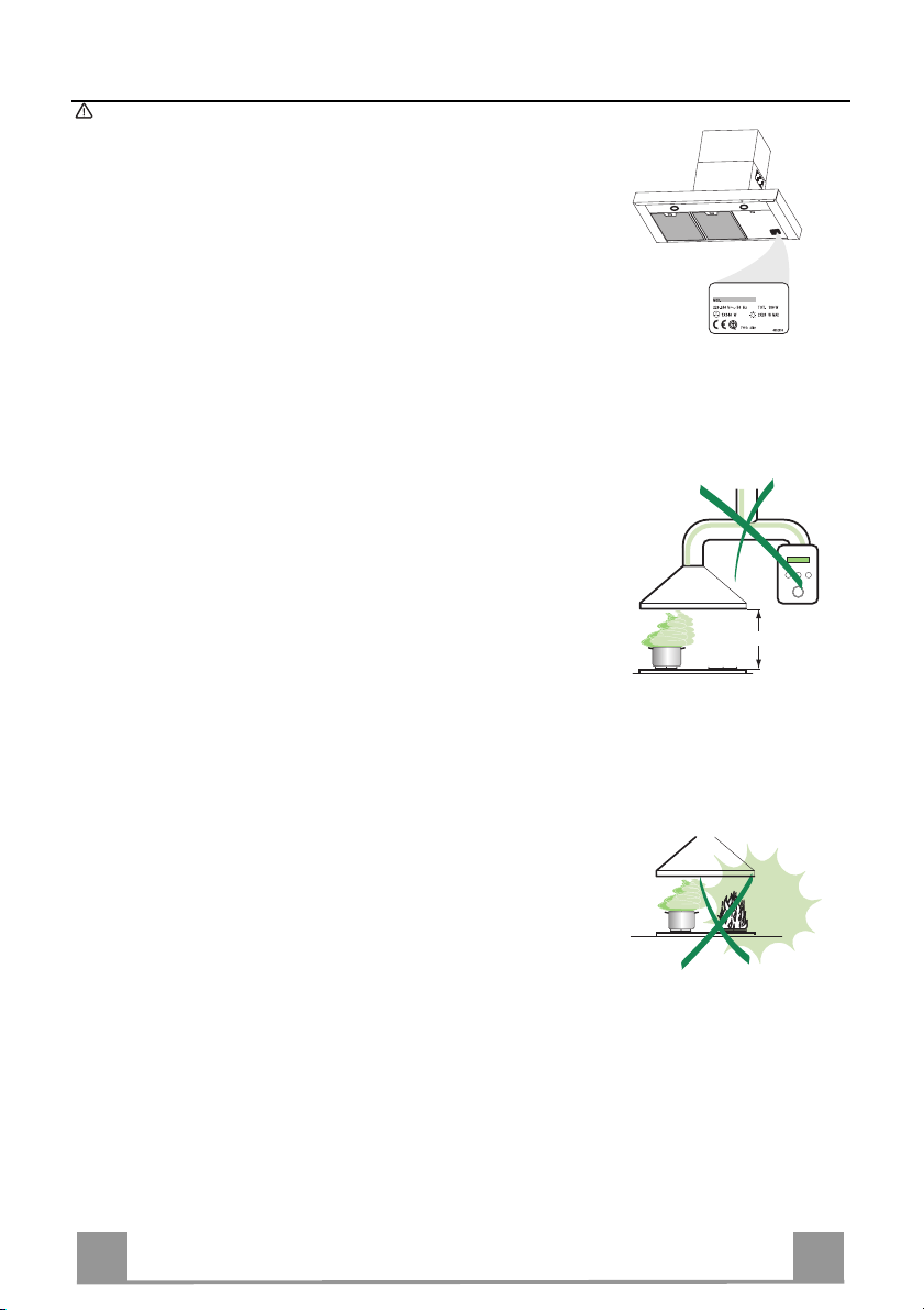
• The minimum safety distance b etween the cooker top and the extr actor
hood is 650 mm.
• Check that the mains voltage corres ponds to that i ndicated on the rati ng
plate fixed to the inside of the hood.
• F or Class I appliances, check t hat the domestic power s upply guara ntees
adequate earthing.
Connect the extractor to the exhaust fl ue through a pipe of minimum di -
ameter 120 mm. The route of the flue must be as short as possible.
• Do not connect the extractor hood to exhaust ducts carrying combustion
fumes (boilers, fireplaces, etc.).
• If the extractor is us ed in conjunction with non -electrical appliances (e. g.
gas burning appliances), a sufficie nt degree of aeration must be guara nteed in the room in order to prevent the backflow of exhaust g as. The
kitchen must have an opening communicati ng directly wi th the open air in
order to guarantee the entry of clean air.
USE
• The extractor hood has been designe d exclusively for domestic use to
eliminate kitchen smells.
• Never use the hood for purposes other than for which it has ben designed.
• Never leave high naked flames under the hood when it is in operation.
• Adjust the flame intensity to direct it onto the bottom of the pan only, m aking sure that it does not engulf the sides.
• Deep fat fryers must be continuously moni tor ed du ring use: overheated oil
can burst into flames.
• Do not flambè under the range hood; risk of fire
• This appliance is not intended f or use by pe rsons (incl uding c hildr en) wit h
reduced physical, sensory or mental capabilities, or lack of experience
and knowledge, unless they have been given supervision or instruction
concerning use of the appliance by a person responsible for their safety.
• Children should be supervised to ensure that they do not pl ay with the
appliance
MAINTENANCE
• Switch off or unplug the appl iance from the m ains supply before carrying
out any maintenance work.
• Clean and/or replace the Filters after the specified time period.
• Clean the hood using a damp cloth and a neutral liquid detergent.
4
4
Page 5
EN
CHARACTERISTICS
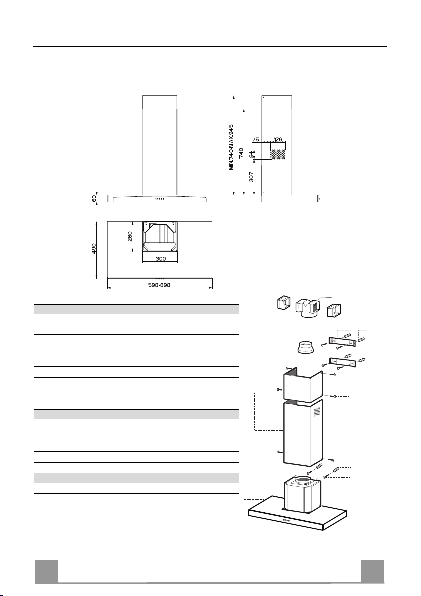
Dimensions
Components
Ref. Q.ty Product Components
1 1 Hood Body, complete with: Controls, Light, Blower,
2 1 Telescopic Chimney comprising:
2.1 1 Upper Section
2.2 1 Lower Section
9 1 Reducer Flange ø 150-120 mm
14.1 2 Air Outlet Connection Extension
15 1 Air Outlet Connection
Ref. Q.ty Installation Components
7.2.1 2 Upper Chimney Section Fixing Brackets
11 6 Wall Plugs
12a 6 Screws 4,2 x 44,4
12c 6 Screws 2,9 x 9,5
Filters
Q.ty Documentation
1 Instruction Manual
15
14.1
12a
7.2.1 11
9
2.1
2
2.2
1
12c
12a
11
5
5
Page 6
EN
INSTALLATION
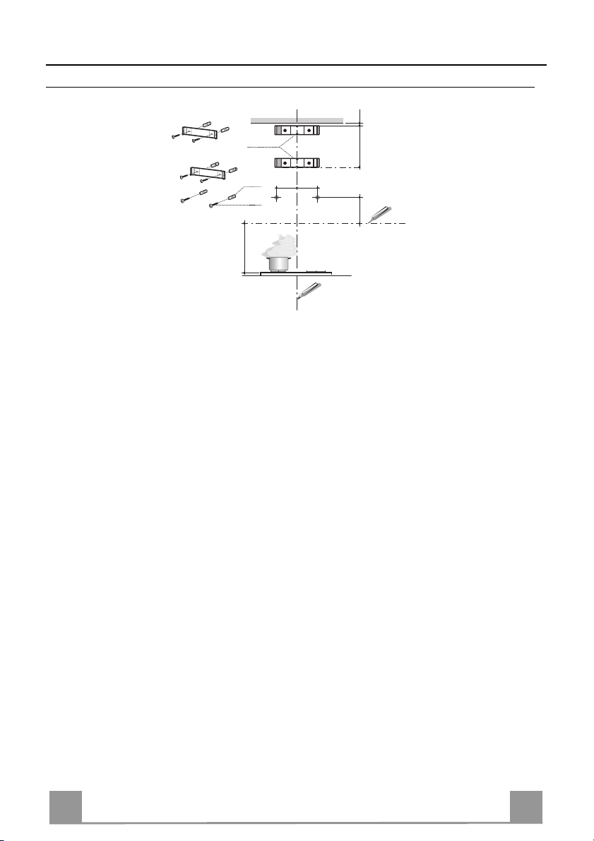
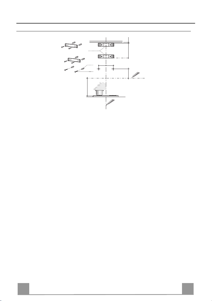
Wall drilling and bracket fixing
7.2.1
1÷2
X
11
12a
116
116
320
650 min.
Wall marking:
• Draw a vertical line on the supporting wall up to the ceiling, or as high as practical, at the
centre of the area in which the hood will be installed.
• Draw a horizontal line at 650 mm above the hob. Place bracket 7.2.1 on the wall as shown
about 1-2 mm from the ceiling or upper limit aligning the centre (notch) with the vertical
reference line.
• Mark the wall at the centres of the holes in the bracket.
• P l ace br acket 7.2.1 on the wall as shown at X mm below the first bracket (X = height of the
upper
chimney section supplied), aligning the centre (notch) with the vertical line.
• Mark the wall at the centres of the holes in th e br acket.
• Mark a reference point as in dicated at 116 mm from the vertical reference li ne and 320 mm
above the horizontal reference l ine.
• Repeat this operation on the other side.
• Drill ø 8 mm holes at all the centre points marked.
• Insert the wall plugs 11 in the holes.
• Fix the brackets using the 12a (4,2 x 44,4) screws supplied.
• Insert the two screws 12a (4,2 x 44,4) supplied in the hood body fixing holes, leaving a gap
of 5-6 mm between the wall and the head of the screw.
6
6
Page 7

EN
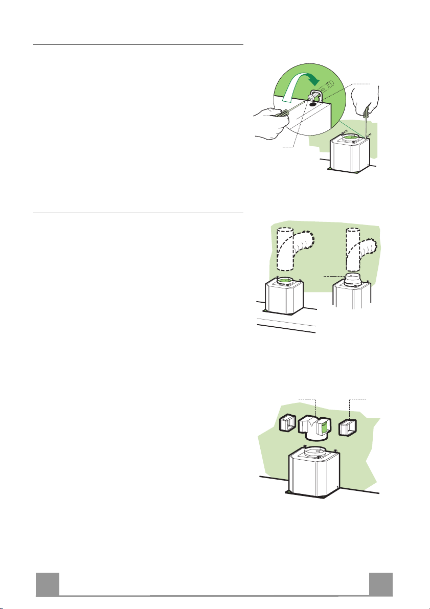
Mounting the hood body
• Before attaching the hood body, tighten the two
screws Vr located on the hood body mounting points.
• Hook the hood body onto the screws 12a.
• Fully tighten the support screws 12a.
• Adjust the screws Vr to level the hood body.
Connections
DUCTED VERSION AIR EXHAUST SYSTEM
When installing the ducted version, connect th e hood to
the chimney using either a flexible or rigid pipe ø 150
or 120 mm, the choice of which is left to the installer.
• To install a ø 120 mm air exhaust connection, insert
the reducer flange 9 on the hood body outlet.
• Fix the pipe in position using sufficient pipe clamps
(not supplied).
• Remove possible charcoal filters.
Vr
12a
ø 120ø 150
9
RECIRCULATION VERSION AIR OUTLET
• Push fit connection 15 onto the hood body outlet.
• Insert the connection extension pieces laterally 14.1
in connection 15.
• Make sure that the outlet of the extension pieces 14.1
is horizontally and vertically aligned with the chimney outlets. If this is not the case, adjust the posit ion
by either reversing the connection extension pieces
14.1 and then reassemble as described previously.
• Ensure that the activated charcoal filters have been
inserted.
14.115
7
7
Page 8
EN
ELECTRICAL CONNECTION
12c
2.1
2.2
2
7.2.1
12c
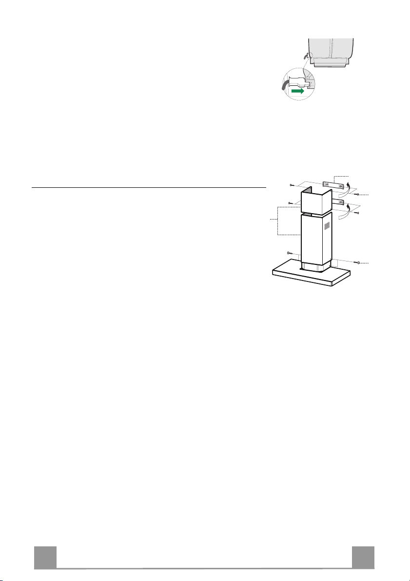
• Connect the hood to the mains through a two-pole switch having a contact gap of at least 3 mm.
• Re move the grease filters (see paragraph Maintenance) being
sure that the conn ector of the feeding cable is correctly inserted
in the socket placed on th e side of the fan.
Chimney assembly
Upper exhaust Chimney
• Slightly widen the two sides of the upper chimney and hook
them behind the brackets 7.2.1, making sure that they are well
seated.
• Secure the si des to the brackets u sing the 4 screws 12c (2,9 x
9,5) supplied.
Lower exhaust Chimney
• Slightly widen the two sides of the chimney and hook them
between the upper chimney and the wall, making sure that they
are well seated.
• Fix the lower part laterally to the hood body using the 2 screws
12c (2,9 x 9,5) supplied.
8
8
Page 9

EN
USE
2
LT1T2 T3 T4
3
4/I
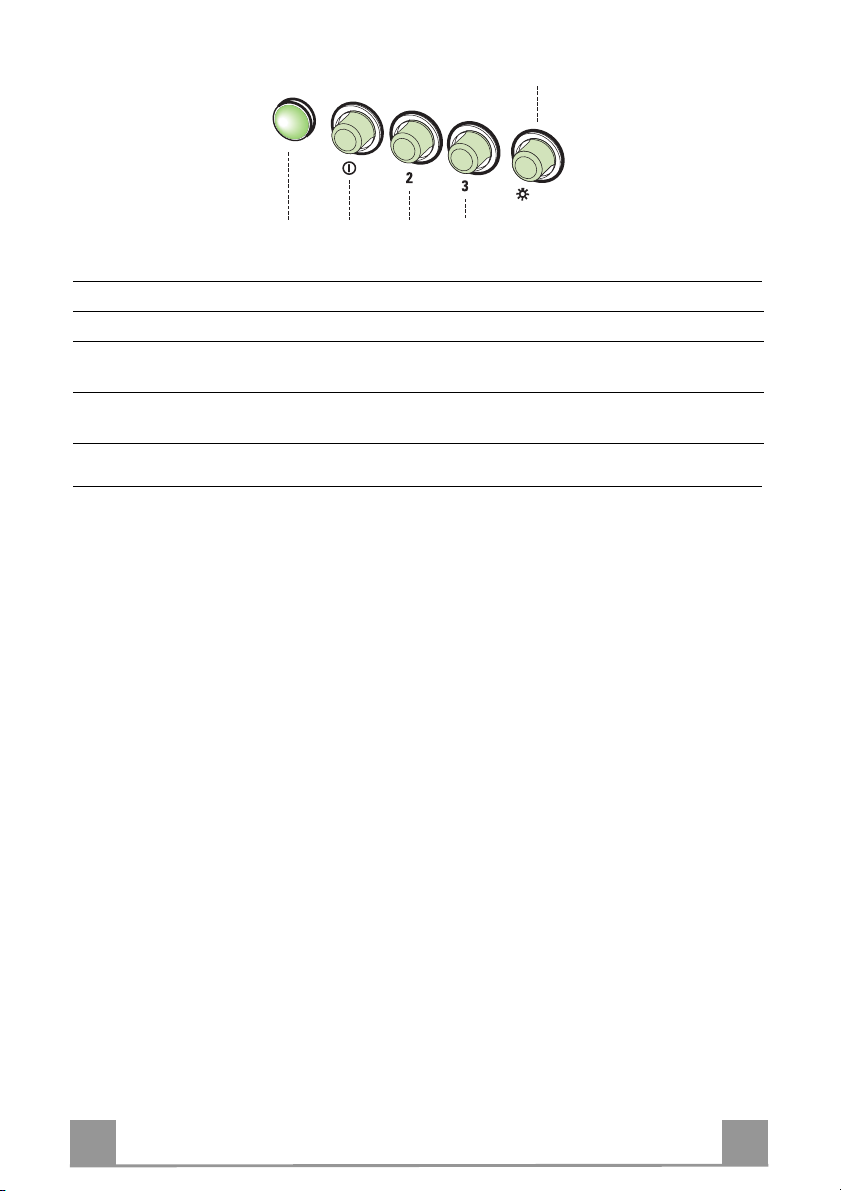
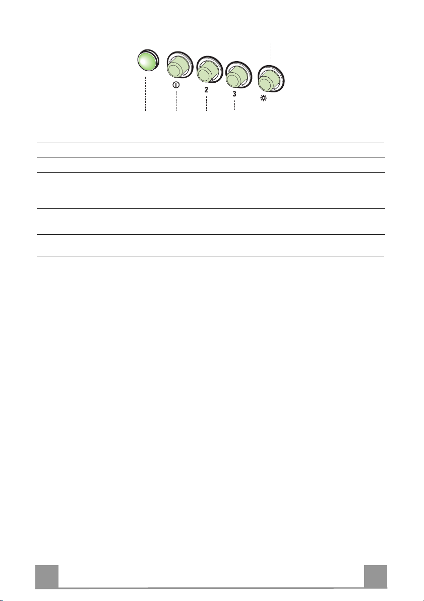
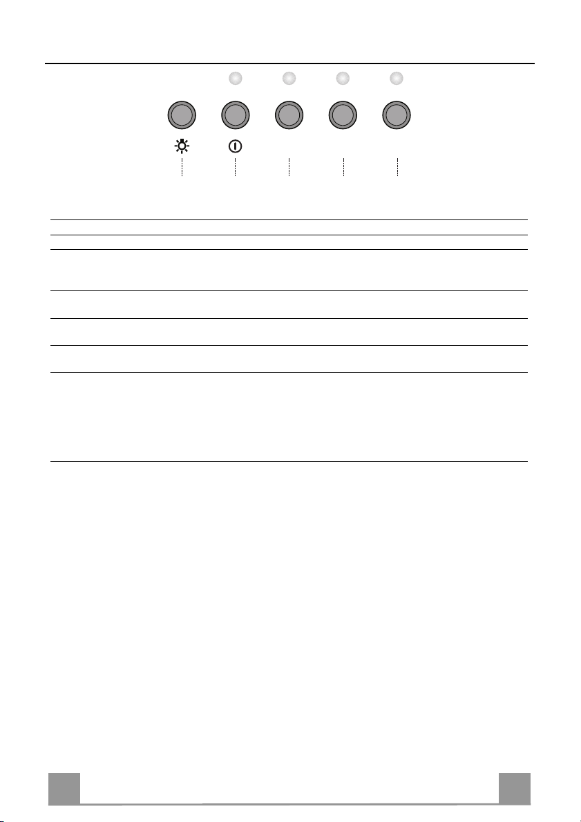
Control panel
KEY LED FUNCTIONS
L 0/1 Light Turns lighting on and off.
T1 0/1 Motor on First speed.
When pressed for about 1 seconds the motor is switched off.
T2 Speed on Second speed.
T3 Speed on Third speed.
T4 Speed Fixed Max. speed
Flashing Intensive speed.
Suitable for the strongest cooking vapours and odours. The func-
tion becomes active when th e button is pushed for about 2 seconds. After 10 minutes of functioning it turns off automatically.
This function can be interrupted by means of pressing any of the
buttons.
9
9
Page 10
EN 110
L
V1 V2 V3S
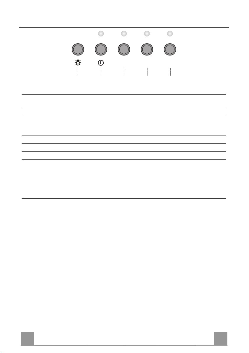
L Light Switches the lighting system on and off.
S Led Motor running led.
V1 Motor Switches the extractor motor on and off at low speed. Used to provide a contin-
uos and silent air change in the presence of light cooking vapours.
V2 Speed Medium speed, suitable for most operating conditions given the optimum
treated air flox/noise level ratio.
V3 Intensive Maximum speed, used for eliminating the highest coo king vapour emission,
including long periods.
Page 11
EN 111
MAINTENANCE
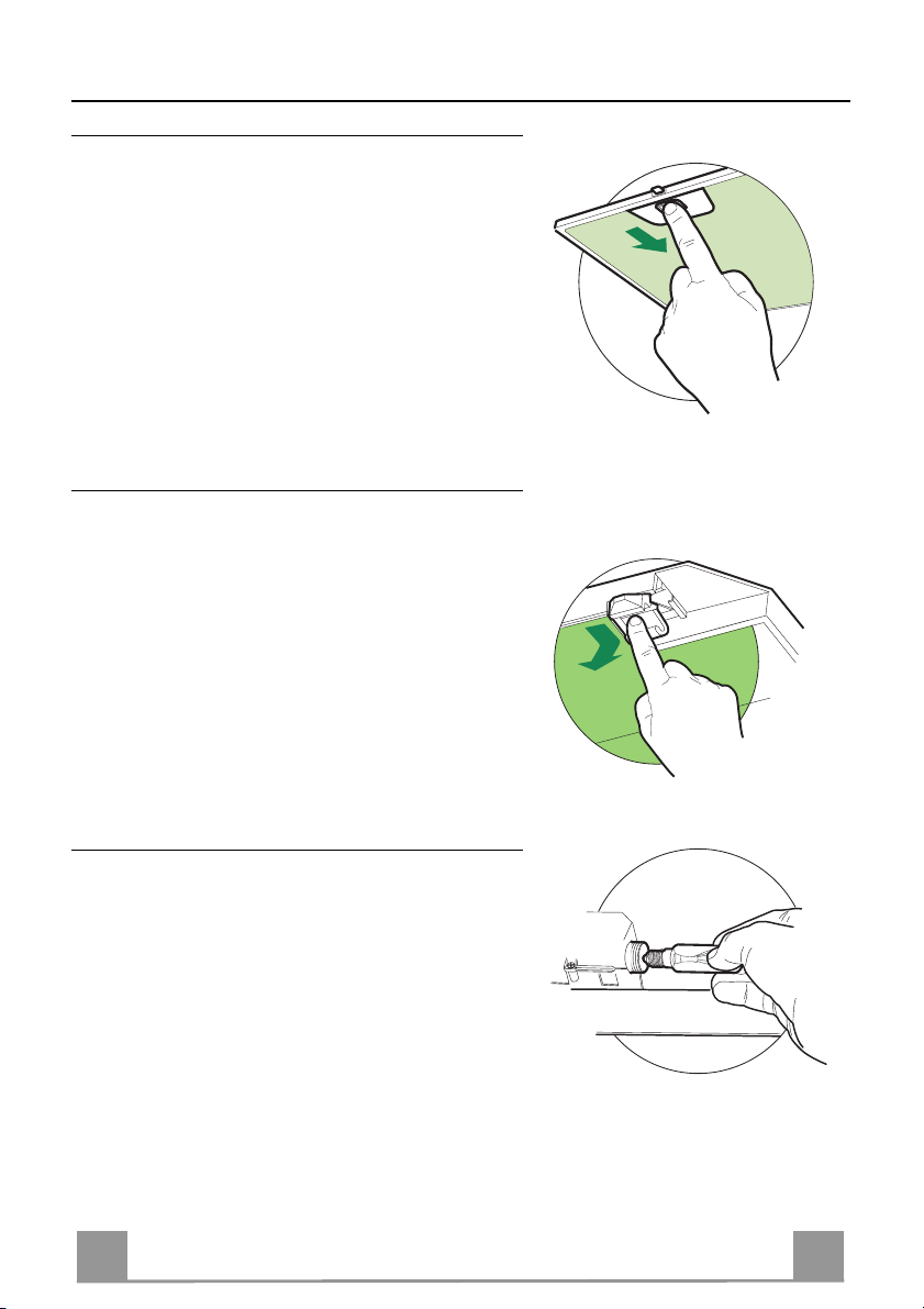
Grease filters
CLEANING META L SELF- SUPPORTI NG GREASE FILTERS
• The filters must be cleaned every 2 months of operation, or more frequently for particularly heavy usage,
and can be washed in a dishwasher.
• Re move the filters one at a time by pushing them towards the back of the group and pulling down at the
same t ime.
• Wash the filters, taking care not to bend them. Allow
them to dry before refitting.
• When refitting the filters, make sure that the handle
is visible on the outside.
Activated charcoal filter (Recirculation version)
REPLACING THE ACTIVATED CHARCOAL FILTE R
• The filter is not washable and cannot be regenerated,
and must be replaced approximat ely every 4 months
of operation, or more frequently for particularly
heavy usage.
• Remove the metal grease filters.
• Remove the saturated activated carbon filter by releasing the fixing hooks.
• Fit the new filter by hooking it into its seating.
• Refit the metal grease filters.
Lighting
LIGHT REPLACEMENT
40 W incandescent light.
• Remove the metal grease filters.
• Unscrew the bulbs and rep lace them with new ones
having the same characteristics.
• Replace the metal grease filters.
Page 12

FR 112
CONSEILS ET SUGGESTIONS
650 mm min.
La présente notice d'emploi vaut pour plusieurs versions de l'appareil. Elle
peut contenir des de scriptions d'acce ssoires ne figuran t pas dans votre appareil.
INSTALLATION
• Le fabricant décline toute responsabilité en cas de dommage dû à une installation non corr ecte ou non conforme aux règles de l’art.
• La distance minimale de sécurité entre le plan de cuisson et la hotte doit être
de 650 mm au moins.
• Vérifier que la tension du secteur correspond à la valeur qui figure sur la plaquette apposée à l’intérieur de la hotte.
• Pour les Appareil s appartenant à la I
mise à la te rre de l’installation électrique domestiqu e ait été effectuée confor-
mément aux normes en vigueur.
• Connecter la hotte à la sortie d’air aspiré à l’aide d’une tuyauterie
d’un diamètre égal ou supérieur à 120 mm. Le parcours de la
tuyauterie doit être le plus court possible.
• Eviter de connecter la hotte à des conduites d’évacuation de fumées
issues d’un e combustion tel que (Chaudière, cheminée, etc…).
• Si vous utilisez des appareils qui ne fonctionnent pas à l’électricité
dans la pièc e ou est installée la hotte (par exemple: des apparei ls
fonctionnant au gaz), vous devez prévoir une aération suffisante du milieu. Si
la cuisine en est dépourvue, pratiquez une ouverture qui communique avec
l’extérieur pour garantir l’infiltration de l’air pur.
UTILISATION
• La hotte a été conçue exclusivement pour l’usage domestique, dans le but
d’éliminer les odeurs de la cuisine.
• Ne jamais utiliser abusivement la hotte.
• Ne pa s laisser les flammes libres à forte intensité quand la ho tte est en service.
• Toujours régler les flammes de manière à éviter toute sortie latérale
de ces derni ères par rapport au fond des marmit es.
• Contrôler les friteuses lors de l’utilisation car l’huile surchauffée
pourrait s’enflammer.
• Ne pas préparer d’aliments flam bés sous la hotte d e cuisine : risque d’incendie
• Cet appareil ne d oit pa s être utilisé pa r des personn es (y comp ris le s en fants)
ayant des capacités psych iques, sen sorielles ou mentale s réduites, ni pa r des
personnes n’ayant pas l’expérience et la connaissance de ce type d’appareils,
à moins d'être sous le contrôle et la formation de personnes responsables de
leur sécurité.
• Les enfants doivent être surveillés pour s'assurer qu'ils ne jouent pas avec
l'appareil.
ENTRETIEN
• Avant de procéder à toute opération d’entretien, retirer la hotte en retirant la
fiche ou en actionnant l’interrupteur général.
• Effectuer un entretien scrupuleux et en temps dû des Filtres, à la cadence
conseillée.
• Pour le nettoyage des surfaces de la hotte , il suffit d’u tiliser un ch iffon humide
et détersif liquide neutre.
ère
Classe, veiller à ce que la
Page 13

FR 113
CARACTERISTIQUES
Encombrement
Composants
Réf. Q.té Composants de Produit
1 1 Corps Hotte équipé de:Comandes,
Lumière, Groupe Ventilateur,Filtres
2 1 Cheminée Télescopique formée de :
2.1 1 Cheminée Supérieure
2.2 1 Cheminée Inférieure
9 1 Flasque de Réduction ø 150-120 mm
14.1 1 Rallonge Raccord Sortie Air
15 1 Raccord Sortie Air
Réf. Q.té Composants pour l ’installation
7.2.1 2 Brides Fixation Ch emi né e Su péri eur e
11 6 Chevilles
12a 6 Vis 4,2 x 44,4
12c 6 Vis 2,9 x 9,5
Q.té Documentation
1 Manuel d’instructions
15
14.1
12a
7.2.1 11
9
2.1
2
2.2
1
12c
11
12a
Page 14

FR 114
INSTALLATION
Perçage Paroi et Fixation Brides
7.2.1
1÷2
X
11
12a
116
116
320
650 min.
Tracer sur la paroi:
• une ligne verticale allant jusqu’au plafond ou à la limite supérieure, au centre de la zone
prévue pour le montage de la hotte;
• une ligne horizontale à 650 mm min. au-dessus du plan de cuisson.
• Poser comme indiqué une bride 7.2.1 sur la paroi à 1-2 mm du plafond ou de la limite supérieure, en alignant son centre (découpes) sur la ligne verticale de repère.
• Marquer les centres des trous rainurés de la bride.
• Poser comme indiqué la bride 7.2.1 à X mm sous la première bride (X = hauteu r cheminée
supérieure fournie), en al ignant son centre (découpes) sur la ligne verticale de repère.
• Marquer les centres des trous rainurés de la bride.
• Marquer comme indiqué, un point de référence à 116 mm de la ligne verticale de repère, et
320 mm au-dessus de la ligne horizontale de repère.
• Répéter cette opération sur le côté opposé.
• Percer de ø 8 mm tous les points marqués.
• Insérer les chevilles 11 dans les trous.
• Fixer les brides en utilisant les vis 12a (4,2 x 44,4) fournies.
• Visser les 2 vis 12a (4,2 x 44,4) fournies dans les trous de fixation du corps hotte, en laissant
un espace de 5-6 mm entre le mur et la têt e de la vis.
Page 15

FR 115
Montage Corps Hotte
• Avant d’accrocher le co rps hotte, serrer les deux vis
Vr situées sur les points d’accrochage du corps hotte.
• Accrocher le corps hotte aux vis 12a prévues à cet
effet.
• Serrer définitivement les vis 12a de support.
• Agir sur les vis Vr pour niveler le corps hotte.
Branchements
SORTIE AIR VERSION ASPIRANTE
En cas d’installation en version aspirante, brancher la
hotte à la tuyauterie de sortie via un tube ri-gide ou
flexible de ø 150 ou 120 mm, au choix de l’installateur.
• En cas de branchement avec un tube de ø120 mm,
insérer le flasque de réduction 9 sur la sortie du corps
de la hotte.
• Fixer le tube par des colliers appropriés. Le matériau
nécessaire n’est pas fourni.
• Retirer les éventuels filtres anti-odeur au charbon
actif.
Vr
12a
ø 120ø 150
9
SORTIE AIR VERSION FILTRANTE
• Insérer sous pression le raccord 15 sur la rallonge
corps hotte 14.
• Insérer latéralement l es rallonges raccord 14.1 sur le
14.115
raccord 15.
• S’assu rer que la sortie des rallonges raccord 14.1 se
trouve au niveau des bouches de la cheminée aussi
bien en horizontal qu’en vertical. Si tel n’est pas le
cas, ajuster la position en inversant les rallo nges raccord 14.1 et remont er l es pièces comme décrit au préalable.
• S’assurer de la présence des filtres anti-odeur au
charbon actif.
Page 16

FR 116
BRANCHEMENT ELECTRIQUE
12c
2.1
2.2
2
7.2.1
12c
• Brancher la hotte sur le secteur en interpo sant un interrupteur
bipolaire avec ouvertu re des contacts d’au moins 3 mm.
• Enlever les filtres à graisse (voir § "Entretien") et s'assurer que
le connecteur du câbl e d'al imentati on so it bien bran ché dan s la
prise du diffuseur.
Montage Cheminée
Cheminée supérieure
• Elargir légèrement les deux bords latériaux, et les accrocher
derrières les brides 7.2.1; refermer jusqu’à la butée.
• Fixer latéralement aux brides à l’aide des 4 vis 12c fournies.
Cheminée inférieure
• Elargir légèrement les deux bords latériaux de la Cheminée et
les accrocher entre la Cheminée supérieure et la paroi; refermer
jusqu’à la butée.
• Fixer latéralement la partie inférieure au corps hotte, à l’aide
des deux 2 vis 12c fournies.
Page 17
FR 117
UTILISATION
2
LT1T2 T3 T4
3
4/I
Tableau de commande
TOUCHE LED FUNCTIONS
L0/1 éclairage Allume et éteint l'éclairage.
T10/1 Moteur Allumé Première vitesse.
T2 Vitesse Allumé Deuxième vitesse.
T3 Vitesse Allumé Troisième vitesse.
T4 Vitesse Fixe Vitesse maximum.
Clignotement Vitesse imtensive.
Cette vitesse est conseillée pour de grandes émissions de va-
Cette touche permet d’éteindre la hotte en y pressant pour environ 2
secondes.
peurs de cuisson. Elle peut être insérée en pressant pour 2 secondes environ la touche. Elle s’éteint en automatique après
10 minutes de fonctionnement. On peut l’éteindre manuellement en pressant n’importe quelle touche.
Page 18
FR 118
L
V1 V2 V3S
L Lumières Allume et éteint l’installation de l’éclairage.
S Del Del allumage Moteur.
V1 Moteur Met en marche et à l’arrêt le moteur aspiration à vitesse minimale, pour un re-
change d’air permantent particulièrement silencieux en cas de faibles vapeurs
de cuisson.
V2 Vitesse Vitesse moyenne pour la plupart des conditions d’utilisation, étant donné le
rapport optimal entre débit d’air traité et niveau sonore.
V3 Vitesse Vitesse maximum, pour faire face aux émissions maximum de vapeur de cuis-
son, même pendant des temps prolongés.
Page 19

FR 119
ENTRETIEN
Filtres anti-graisse
NETTOYAGE FILTRE S ANTI -GRAISS E METALLI QUES AUTOPO RTEUR S
• Lavables au lave-vais selle, ils doivent être lavé s environ tous les 2 mois d’emploi ou plus fréquemment
en cas d’emploi particulièrement intense.
• Retirer les filtres l’un aprés l’autre, en les poussant
vers la partie arrière du groupe et en ti rant simultanément vers le bas.
• Laver les filtres en évitant de les plier et les laisser
sécher avant de les remonter.
• Remonter les filtres en veillant à ce que la poignée
reste vers la partie visible externe
Filtre anti-odeur (Version filtrante)
REMPLACEMENT FILTRE AU CHARBON ACTIF
• Ni lavable, ni régénérable, le remplacer au moins
tous les 4 mois d’emploi ou plus fréquemment en cas
d’emploi particulièrement intense.
• Retirer les filtres anti-graisse métalliques.
• Retirer le filtre anti-odeur au charbon actif colmaté,
en agissant sur les crochets p révus à cet effet.
• Monter le nouveau filtre anti-odeur au charbon actif.
• Remonter les filtres anti-graisse métalliques.
Eclairage
REMPLACEMENT LAMPES
Lampes à incandescence de 40 W
• Retirer les filtres anti-graisse métalliques.
• Dévisser les lampes et les remplacer par de nouvelles
avec les mêmes caractéristiqu es.
• Remonter les filtres anti-graisse métalliques.
Page 20

DE 220
EMPFEHLUNGEN UND HINWEISE
650 mm min.
Diese Gebrauchsanleitung gilt für mehrere Geräte-Ausführungen. Es ist mög-
lich, dass einzelne Ausstattungsmerkmale beschrieben sind, die nicht auf Ihr
Gerät zutreffen.
MONTAGE
• Der Hersteller haftet nicht für Schäden, die auf eine fehlerhafte und unsachgemäße Montage zurückzuführen sind.
• De r minimale Sicherhei tsabstand zwischen Ko chmulde und Haube mu ss 650
mm betragen.
• Prüfen, ob die Netzspannung mit dem Wert auf dem im Haubeninneren angebrachten Schild üb er ei ns ti mmt.
• Bei Geräten der Klasse I ist sicherzustellen, dass die elektrische Anlage des
Wohnhauses über eine vorschri ftsmäßige Erdung verfügt.
• Das Anschlussrohr der Haube zur Luftaustrittsöffnung muss einen Durchmesser von 120 mm oder darüber aufweisen. Der Rohrverlauf muss so kurz wie
möglich sein.
• Die Haube darf an keine Entlüftungsschächte ange schlossen werden, in die
Verbrennungsgase (Heizkessel, Kamine usw.) geleitet werden.
• Werden im Raum außer der Dunstabzugshaube andere, nicht elektrisch betriebene (z.B. gasbetrie bene) Geräte verwendet, mu ss für eine ausreichende
Belüftung gesorgt werden. Sollte die Küche diesbezüglich nicht entsprechen,
ist an einer Aussenwand eine Öffnung anzubringen, die Frischluftzufuhr gewährleistet.
BEDIENUNG
• Die Dunstabzugshaube ist aussch ließlich zum Einsatz im privaten Haushalt
und zur Beseitigung von Küchengerüchen vor gesehen.
• Unsachgemäßer Einsatz der Haub e ist zu unterlassen.
• Große Flammen bei eingeschalteter Haube niemals u nbedeckt lassen.
• Die Intensivität der Flamme ist so zu regulieren, dass sie den Topfboden nicht
überragt.
• Frittiergeräte müssen während des Gebrauchs stets beaufsichtigt werden:
überhitztes Öl kann sich entzünden.
• Keine flambierten Speisen unter der Abzugshaube zubereiten: Brandgefahr.
• Dieses Gerät darf n icht von Person en, auch Kind ern, m it verm inderte n psych ischen, sensorischen und geistigern Fähigkeiten, oder von Personen ohne Erfahrung und Kenntnisse benutzt werden, sofern sie nicht von für ihre Sicherheit verantwortlichen Personen beaufsichtigt und beim Gebrauch des Geräts
angeleitet werden.
• Kinder dürfen sich ni cht unbeau fsichtigt in der Nähe des Ge räts aufha lten und
auf keinen Fall mit dem Gerät spiel en.
WARTUNG
• Bevor Wartungsarbeiten durchgeführt werden, muss die Stromzufuhr zur Haube unterbrochen werden, indem der Stecker gezogen oder der Hauptschalter
abgeschaltet wird.
• Bei der Filterwartung müssen die vom Hersteller empfohlenen Zeiträume zum
Austauschen der Filter genauestens eingehalten werden.
• Zur Reinigung der Haubenflächen Wir empfehlen ein feuchtes Tuch und ein
mildes Flüss igreinigungsmit tel.
Page 21

DE 221
CHARAKTERISTIKEN
Platzbedarf
Komponenten
Pos. St. Produktkomponenten
1 1 Haubenkörper mit Schaltern,Beleuchtung,
Gebläsegruppe,Filter
2 1 Teleskopkamin bestehend aus:
2.1 1 oberer Kaminteil
2.2 1 unterer Kaminteil
9 1 Reduzierflansch ø 15 0-120 mm
14.1 2 Verlängerung Luftaustritt-Anschlussstück
15 1 Luftaustritt-Anschlussstück
Pos. St. Montagekomponenten
7.2.1 2 Befestigungsbügel o berer Kaminteil
11 6 Bügel
12a 6 Schrauben 4,2 x 44,4
12c 6 Schrauben 2,9 x 9,5
St. Dokumentation
1 Bedienungsanleitung
15
14.1
12a
7.2.1 11
9
2.1
2
2.2
1
12c
11
12a
Page 22
DE 222
MONTAGE
Bohren der Befestigungslöcher und Fixieren der Befestigungsbügel
7.2.1
1÷2
X
11
12a
116
116
320
650 min.
Nachstehende Linien an die Wand zeichnen:
• eine vertikale Linie bis zur Decke oder oberen Begrenzung, und zwar in der Mitte des Bereiches, in dem die Haube montiert werden soll;
• eine horizontale Linie mit einem minimalen Abstand von 650 mm zur Kochfläche.
• Einen Bügel 7.2.1 zirka 1-2 mm unter der Decke oder oberen Begrenzung an die Wand legen und seinen Mittelpunkt (Einschnitte) auf die vertikale Bezugslinie ausrichten.
• Die Mitte der beiden Bügellöcher an der Wand markieren.
• Den zweiten Bügel 7.2.1 an die Wand legen, wobei ein Abstand X mm vom oberen Bügel
einzuhalten ist (X = Höhe des jeweiligen oberen Kaminteils); den Mittelpunkt (Einschnitte)
auf die vertikale Bezugslinie ausrichten.
• Die Mitte der Bügellöcher an der Wand markieren.
• Wie beschrieben einen Bezugspunkt 116 mm von der vertikalen Bezugslinie und 320 mm
oberhalb der horizontalen Bezugslinie kennzeichnen.
• Gleichermaßen an der gegenüberliegenden Seite vorgehen.
• Mit einem Bohrer ø 8 mm die markierten Punkte bohren.
• Die Dübel 11 in die Bohrungen einfügen.
• Die Bügel mit den mitgelieferten Schrauben 12a (4,2 x 44, 4) fixieren.
• 2 der mitgelieferten Schrauben 12a (4,2 x 44,4) bei den Befestigungslöchern des Haubenkörpers einschrauben, wobei zwischen Wand und Schraubenkopf ein Freiraum von 5-6 mm
zu belassen ist.
Page 23
DE 223
Montage des Haubenkörpers
• Bevor der Haubenkörper eingehakt wird, die 2
Schrauben Vr bei den Haubenkörper-Anhakpunkten
festziehen.
• Den Haubenkörper be i de n Sc hraube n 12a einhängen.
• Die Halteschrauben 12a definitiv festziehen.
• Den Haubenkörper mit Hilfe der Schrauben Vr aus-
richten.
Anschlüss in abluftversion
Bei Abluftbetrieb kann die Haube vom Installateur
wahlweise mittels Rohr oder Schlauch (ø 150 oder 120
mm) an die Außenrohrleitung angeschlossen werden.
• Bei Verwendung eines Anschlussrohres ø 120 den
Reduzierflansch 9 am Haubenaustritt anbringen.
• Das Roh r mit geeigneten Rohrschellen fixieren. Das
hierzu erforderliche Material wird nicht mitgeliefert.
• Eventuell vorhandene Aktivkohlefilter entnehmen.
Vr
12a
ø 120ø 150
9
ANSCHLUSS IN UMLUFTVERSION
• Den Anschluss 15 beim Luftaustritt des Haubenkörpers eindrücken.
• Die Verlängerungen 14.1 beim Anschluss 15 seitlich
14.115
einfügen.
• Überprüfen, ob die Verlängerungen 14.1 mit den entsprechenden Kaminstutzen sowohl horizontal wie
auch vertikal übereinstimmen. Sollte dies nicht der
Fall sein, müssen die Verlängerungen 14.1 miteinander vertauscht und wie zuvor beschrieben wieder zusammengebaut werden.
• Kontrollieren, ob der Aktivkohle-Geruchsfilter vorhanden ist.
Page 24

DE 224
ELEKTROANSCHLUSS
12c
2.1
2.2
2
7.2.1
12c
• Bei Anschluss der Haube an das Stromnetz muss ein zweipoliger Schalter mit einem Öffnungsweg von mindestens 3 mm
zwischengeschaltet werden.
• Entfernen Sie die Fettfilter (s. Abschnitt „Wartung“) und versichern Sie sich, daß di e Kabelverbindung in die Steckd ose des
Gebläses einwandfrei eingesteckt wird.
Kaminmontage
Oberer Kaminteil
• Die beiden seitlichen Schenkel leicht auseinanderbiegen, hinter
den Bügeln 7.2.1 einhängen und bis zum Anschlag wieder
schließen.
• Bei den Bügeln mit Hilfe der 4 mitgelieferten Schrauben 12c
fixieren.
Unterer Kaminteil
• Die beiden seitlichen Schenkel des Kaminteils leicht auseinanderbiegen, zwischen dem oberen Kaminteil und der Wand einhängen und bis zum Anschlag wieder schließen.
• Den unteren Teil seitlich am Haubenkörper mit 2 der mitgelieferten Schrauben 12c fixieren.
Page 25
DE 225
BEDIENUNG
2
LT1T2 T3 T4
3
4/I
Bedienfeld
TASTE LED FUNKTION
L 0/1 Beleuchtung Ein- und Ausschalten der Beleuchtung.
T1 0/1 Motor Eingeschaltet Erste Geschwindigkeitsstufe.
Schaltet die Haube aus wenn die Taste für ungefähr 1
T2 Geschwindig- Eingeschaltet Zweite Geschwindigkeitsstufe.
keitsstufe
T3 Geschwindig- Eingeschaltet Dritte Geschwindigkeitsstufe.
keitsstufe
T4 Geschwindig- Ständiges Höchste Geschwindigkeitsstufe.
keitsstufe Aufleuchten
Blinklicht Intensivstufe.
Bei sehr starker Kochdunstentwicklung geeignet. Wird
Sekunde gedrückt wird
durch 2 Sekunden l anges Drücken au f diese Taste akti viert. Nach 10 Minut en schaltet sich das Gebläse au tomatisch auf die vorher gewählte Stufe zurück. Kann
auch manuell unterbrochen werden indem man einfach
auf eine andere Taste drückt.
Page 26

DE 226
L
V1 V2 V3S
L Beleucht. Schaltet die Beleuchtung ein und aus.
S Led Betriebsanzeigela mpe.
V1 Motor Schaltet den Gebläsemotor mit minimaler Geschwindigkeit ein oder aus. Diese
Stufe ist für einen ständigen und besonders leisen Luftaustausch bei geringer
Kochdunstentwickl ung geeignet.
V2 Geschw. Mittlere Gebläsestufe, eignet sich aufgrund des guten Verhältnisses zwischen
Fördervolumen und Geräuschentwicklung für die meisten Anwendungssituationen.
V3 Geschw. Höchste Gebläsestufe, eignet sich für starke Kochdunstentwicklung, auch über
längere Zeit hin.
Page 27

DE 227
WARTUNG
Fettfilter
SELBSTTRAGENDER METALLFETTFILTER REINIGUNG
• Sie müssen nach 2-monatigem Betrieb bzw. bei starkem Einsatz auch häufiger gerei nigt werden, was im
Geschirrspüler möglich ist.
• Die Filter nacheinander aushaken, indem sie auf die
Rückseite der Gruppe geschoben und gleichzeitig
nach unten gezogen werden.
• Die Filter reinigen (darauf achten, sie nicht zu verbiegen) und vor der Remontage trocknen lassen.
• Bei der Remontage ist darauf zu achten, dass sich der
Griff auf der sichtbaren Außenseite befindet.
Geruchsfilter (Umluftversion)
AUSTAUSCHEN DER AKTIVKOHLE FILTER
• Dieser Filter kann weder gewaschen noch wiederverwendet werden und ist alle 4 Betriebsmonate bzw.
bei starkem Einsatz auch häufiger auszutauschen.
• Die Metallfettfilter entfernen.
• Den gesättigten Aktivkohle-Geruchsfilter aushaken.
• Den neuen Filter in seinem Sitz einhaken.
• Die Metallfettfilter wieder montieren.
• Die Kohlefilter können mit dem Hausmüll entsorgt
werden.
Beleuchtung
AUSWECHSELN DER LAMPEN
Glühlampen 40W
• Die Metallfettfilter entfernen.
• Die Lampen ausschrauben und durch gleichwertige
ersetzen.
• Die Metallfettfilter wieder montieren.
Page 28

NL 228
ADVIEZEN EN SUGGESTIES
650 mm min.
D eze gebruiksaa nwijzing geldt vo or verschillende uitvoeringen van het appa -
raat. Het is mogelijk dat er een aantal kenmerke n worden besch reven die nie t
van toepassing zijn op uw appar aat.
INSTALLATIE
• D e fabrikant aanvaa rdt geen enkele aa nsprakelijkheid voo r schade die voo rtkomt uit onjuiste of niet overeenkomstig de regels der kunst uitgevoerde installaties.
• De minimale veiligheidsafstand tussen de kookplaat en de wasemkap bedraagt 650 mm.
• Contro leer of de netspan ning correspondeert met de spanning d ie aangegeven is op het pl aatje aan de binnenkant van de wase mkap.
• Voor apparaten van klasse I dient u zich ervan te verzekeren dat het elektriciteitsnet in uw huis over een goede aarding beschikt.
• Verbind de wasemkap met de luchtuitlaat door middel van een leiding met een
diameter van 120 mm of groter. De leiding moet een zo kort mogelijke route afleggen.
• Sluit de wasemkap niet aan op afvoerpijpen van rook die geproduceerd is door
verbranding ( verwarmingsketels, open haarden etc.).
• Als er in het vertrek zowel de wasemkap als apparaten die niet op elektriciteit
werken (bijvoorbeeld gasapparaten) worden gebruikt, moet ervoor worden gezorgd dat het ver trek voldoende geventileerd wordt. Indien de keuken geen gat
in de buitenmuur hee ft om de aanvoer van schon e lucht te garande ren, dient
dit gemaakt te worden.
GEBRUIK
• De wasemkap is uitsluitend on tworpen voor huishoudelijk gebruik, voor het
elimineren van kookgeuren. Gebruik de kap nooit op oneigenlijke wijze.
• Laat geen hoog brandende branders onb edekt onder de wasemkap
terwijl deze in werking is.
• Regel de vlammen altij d zo dat ze niet langs de pannen omhoo gkomen.
• Controleer frituurpannen tijdens het gebruik: de oververhitte olie zou vlam
kunnen vatten.
• Er mag niet onder de afzuigkap geflambeerd worden; brandgevaar
• Dit apparaat mag niet worden gebruikt door personen (inclusief kinderen) met
beperkte psychisch e, sensorische en geestelijke vermo ge n s, o f door personen
zonder ervaring en kennis, tenzij ze onder toezich t staan of worden ge ïnstrueerd over het gebruik van het apparaat door personen die verantwoordelijk zijn
voor hun veiligheid.
• Kinderen moeten worden gecontroleerd om er zeker van te zijn dat ze niet met
het apparaat spelen.
ONDERHOUD
• Alvorens onderhoudswerkzaamheden uit te voeren, moet de wasemkap uitgeschakeld worden door de stekker uit het stopcontact te halen of de hoofdschakelaar om te zetten.
• Voer het onderhoud van de filters altijd tijdig en nauwgezet uit,volgens de
aanbevolen intervallen.
• Om de oppervlakken van de kap schoon te maken is het voldoende een vochtige doek en een neutraal reinigingsmiddel te gebruiken.
Page 29

NL 229
EIGENSCHAPPEN
Buitenafmetingen
Onderdelen
Ref. Productonderdelen
1 1 Wasemkap compleet met:Bedieningen,
Licht,Ventilatorgroep,Filters
2 1 Telescopische Schouw Bestaande uit:
2.1 1 Bovenstuk
2.2 1 Onderstuk
9 1 Reductieflens ø 150-120 mm
14.1 2 Verlengstuk Verbindi ngsstuk Luchtuitlaat
15 1 Verbindingsstuk Luchtuitlaat
Ref. Installatieonderdelen
7.2.1 2 Bevestigingsbeugels Bovenstuk va n de
Schouw
11 6 Pluggen
12a 6 Schroeven 4,2 x 44,4
12c 6 Schroeven 2,9 x 9,5
Documentatie
1 Gebruiksaanwijzing
15
14.1
12a
7.2.1 11
9
2.1
2
2.2
1
12c
11
12a
Page 30

NL 330
INSTALLATIE
Boren van gaten in de wand en bevestiging van de draagbeugels
7.2.1
11
12a
116
116
650 min.
1÷2
X
320
Trek de volgende lijnen op de wand:
• een verticale lijn tot aan het plafond of tot aan de bovenlimiet, in het midden van de zone
waar u de wasemkap wilt installeren;
• een horizontale lijn op 650 mm min. boven de kookplaat.
• Plaats, zoals aangegeven, d e b eugel 7.2.1 op 1-2 mm van het plafond of van de bovenlimiet,
en lijn het midden ervan (inkepingen) uit op de verticale referentielijn.
• Teken de middelpunten van de gaten in de beugel af.
• Plaats, zoals aangegeven, de beugel 7.2.1 op X mm onder de eerste beugel (X = hoogte bijgeleverde bovenstuk van de schouw), en lijn het midden ervan (inkepingen) uit op de verticale referentielijn.
• Teken de middelpunten van de gaten in de beugel af.
• Teken, zoals aangegeven, een referentiepunt af op 116 mm van de verticale referentielijn en
op 320 mm boven de horizontale referentielijn.
• Herhaal deze handeling aan de andere kant.
• Boor op de afgetekende punten gaten van ø 8 mm.
• Schuif de pluggen 11 in de gaten.
• Bevestig de beugels met behulp van de bijgeleverde schroeven 12a (4,2 x 44,4).
• Schroef 2 van de bijgeleverde schroeven 12a (4,2 x 44,4) in de gaten voor bevestiging van
de wasemkap en laat hierbij een ruimte van 5-6 mm tussen de wand en de kop van de
schroef.
Page 31

NL 331
Montage van de Wasemkap
• Alvorens de wasemkap vast te haken, de 2 schroeven
Vr, die zich op de bevestigingspunten van de wasemkap bevinden, aanhalen.
• Haak de wasemkap vast aan de schroeven 12a.
• De dragende schroeven 12a definitief aanhalen.
• Draai aan de schroeven Vr om de wasemkap recht te
hangen.
Aansluitingen
LUCHTUITLAAT AFZUIGVERSIE
Bij installatie in afzuigversie, moet u de wasemkap met
de uitlaatleiding verbinden door middel van een starre
of buigzame leiding van ø 150 of 120 mm, naar keuze
van de installateur.
• Voor verbinding met een leiding van ø120 mm, moet
de reductieflens 9 op de uitlaat van de wasemkap
worden aangebracht.
• Zet de leiding vast met geschikt leidingklemmen. Het
benodigde materiaal wordt niet bij de wasemkap geleverd.
• Verwijder de eventuele geurfilters met actieve koolstof.
Vr
12a
ø 120ø 150
9
LUCHTUITLAAT FILTERVERSIE
• Breng verbindingsstuk 15 op de luchtuitgang aan
door het vast te drukken’.
14.115
• Plaats de verlengstukken 14.1 op de zijkant van ver-
bindingsstuk 15.
• Controleer of de uitlaat van het verlengstuk 14.1
overeenstemt met de gaten van de schouw, en dit
zowel horizontaal als vertikaal. Als dit niet het geval
is, dan moet U de compositie aanpassen door de verlengstukken 14.1 .
• Controleer of er een geurfilter met actieve koolstof
aanwezig is.
Page 32

NL 332
ELEKTRISCHE AANSLUITING
12c
2.1
2.2
2
7.2.1
12c
• Sluit de wasemkap aan op de netspanning met een tweepolige
schakelaar ertussen met een opening tussen de contacten van
tenminste 3 mm.
• Verwijder de vetfilters (zie par. "Onderhoud") en verzeker u
ervan dat de stekker van de voedingskabel goed in de contactdoos van de afzuigkap is gestoken.
Montage van de schouw
Bovenstuk van de sc ho uw
• De twee zijplaten enigszins openen, ze vasthaken achter de
beugels 7.2.1 en ze weer zo ver mogelijk sluiten.
• Aan de zijkant aan de beugel bevestigen met de 4 bijgeleverde
schroeven 12c.
Onderstuk van de schouw
• De twee zijplaten van de schouw enigszins openen, ze vasthaken tussen het bovenstuk van de schouw en de wand en ze
weer zo ver mogelijk sluiten.
• Bevestig het onderstuk aan de zijkanten aan de wasemkap met
2 van de bijgeleverde schroeven 12c.
Page 33

NL 333
GEBRUIK
2
LT1T2 T3 T4
3
4/I
Bedieningspaneel
TOETS LED FUNCTIES
L 0/1 Licht Schakelt de verlichting aan en uit.
T1 0/1 Motor brandt Eerste snelheid.
Schakelt de wasemkap uit als hij ongeveer 1seconde ingedrukt
wordt.
T2 Snelheid brandt Tweede snelheid.
T3 Snelheid brandt Derde snelheid.
T4 Snelheid permanent Maximum snelheid.
knipperend Intensieve snelheid.
Geschikt om de sterkste kookd ampen a f te voeren. Wordt geacti -
veerd door de toets ongeveer 2” ingedrukt te houden. Wordt 10
minuten nadat hij in werking getreden is automatisch uitgeschakeld. Kan met de hand worden uitgeschakeld door een willekeurige andere toets in te drukken.
Page 34

NL 334
L
V1 V2 V3S
L Lichten Hiermee schakelt u de verlichting aan en uit.
S Led Led motorinschakeling.
V1 Motor Inschakeling en uitschakeling van de afzuigmotor op minimumsnelheid,
geschikt voor een continue en zeer stille luchtverversing, als er weinig kookdampen zijn.
V2 Snelheid Gemiddelde snelheid, geschikt voor de meeste gebruiksomstandigheden,
gezien de uitstekende verhouding tussen de hoeveelheid behandelde lucht en
het geluidsniveau.
V3 Snelheid Maximumsnelheid, geschikt om de grootste kookdampen tegen te gaan, ook
voor langere tijd.
Page 35

NL 335
ONDERHOUD
Vetfilters
REINIGING VAN DE ZELFDRAGENDE METALEN VETFILTERS
• De filters moeten eens in de 2 maanden of, bij bijzonder intensief gebruik, vaker gereinigd worden, en
kunnen ook in de vaatwasmachine worden gewassen.
• Verwijder de filters één voor één door ze naar de achterkant van de groep te duwen en ze tegelijkertijd
omlaag te trekken.
• Was de filters en vermijd hierbij ze te buigen, en laat
ze drogen alvorens ze terug te plaatsen.
• Plaats de vetfilters terug en let er hierbij op dat de
handgreep zichtbaar blijft.
Geurfilter (filterversie)
VERVANGING FILTER MET ACTIEVE KOOLSTOF
• Het filter kan niet gewassen en niet geregenereerd
worden en moet minstens eens in de 4 maanden worden vervangen, of, bij bijzonder intensief gebruik,
zelfs nog vaker.
• Verwijder de metalen vetfilters.
• V erwijder het verzadigde geurfilter met actieve koolstof door de bevestigingen los te maken.
• Monteer het nieuwe filter door het op zijn plaats vast
te drukken.
• Plaats de metalen vetfilters terug.
Verlichting
VERVANGING VAN DE LAMPEN
Gloeilampen va n 40 W
• Verwijder de metalen vetfilters.
• Schroef de lampen los en vervang ze door nieuwe
lampen met dezelfde eigenschappen.
• Plaats de metalen vetfilters terug.
Page 36

DK 336
RÅD OG ANVISNINGER
650 mm min.
Denne brugervejledning gælder for flere versioner a f apparate t. Der frem stilles
muligvis enk elte dele af tilbehøret, der ikke vedrører jeres apparat.
INSTALLATION
• Producenten kan ikke ho lde s ansva rlig fo r even tuelle skader, der skyldes ukorrekt eller forkert installation.
• Den mindst tilladelige sikkerhedsafstand mellem komfurets top og emhættens
underside er 650 mm.
• Kontrollér, at lysnetspændingen er den samme som den spænding, der er
angivet mærke pladen, der sidder på inde i emhætten.
• For Klasse I apparater skal de t også kontrolle res, at elfo rsyningen er forsyn et
med jord.
• Emhætten kobles til aftrækskanalen ved hjælp af et rør med en min.-diameter
på 120 mm. Afstanden fra emhætten til kanalen skal være så kort som muli g.
• Emhætten må ikke tilsluttes e n kana l, de r fører forb rænding sgasse r ud i det fri
(oliefyr, brændeovne etc.).
• Hvis emhætten skal anvendes i forbindelse med ikke-elektriske apparater
(f.eks. gaskomfur, gaskogeblus), skal det sikres, at lufttilgangen til rummet er
tilstrækkelig, så aftræksg asserne ikke slår tilbage. K økkenet ska l have en åbning, der har direkte forbindelse til det fri, så der er sikret en tilstrækkelig
mængde ren luft.
ANVENDELSE
• Emhætten er udelukkende beregnet til at fjerne em og lugte i køkkener i private husholdninger.
• Emhætten må kun anvendes til det for mål, hvortil den er konstrueret.
• Der må ikke forekomme høj åben ild under emhætten, me ns den anvendes.
• Justér brænderen, så flammerne er rettet direkte mod bunden af panden/gryden – de må ikke nå ud over kanten af bunden.
• Frituregryder skal under brug holdes under konstant opsyn: kogende varm olie
kan sprøjte i nd i flammerne.
• Emhætten må ikke anvendes af børn og personer, som ikke ved, hvordan den
betjenes.
• Apparatet er ikke beregnet til at skulle anvendes af mindre børn eller svækkede personer uden opsy n.
• Undlad at flambere retter under emhætten; der opstår ellers brandf are.
• Dette apparat må ikke anvendes af personer (derunder børn) med nedsatte
psykiske, sensoriske e ller sindsmæssige evner, eller persone r uden erfaring
eller tilstrækkeligt kendskab, med mindre de overvåges eller oplæres i brug af
apparatet af personer, der er ansvarlige for deres sikkerhed.
• Børn skal overvåges for at undgå, at de leger med apparatet.
VEDLIGEHOLDELSE
• Inden apparatet skal vedligeholdes eller rengøres, skal der slukkes for det eller
stikket sk al tages ud af stikkontakten.
• Rengør og/eller udskift filtr ene iht. det angivne tidinterval.
• Rengør emhætten ved hjælp af en fugtig klud og et neutralt flydende rengøringsmiddel.
Page 37

DK 337
APPARATBESKRIVELSE
Dimensioner
Komponenter
Ref. Kvantum Produktkomp onenter
1 1 Emhætte, komplet med Styring, lys, blæser, filtre
2 1 Teleskopisk skorsten indeholdende:
2.1 1 Øverste sektion
2.2 1 Nederste sektion
9 1 Reduktionsflange ø 150-120 mm
14.1 2 Tilslutningsforlænger til luftudtag
15 1 Tilslutning til luftudtag
Ref. Kvantum Install ationsko mponenter
7.2.1 2 Fastgørelsesbøjler til øverste skor stenssektion
11 6 Vægstikkonttakter
12a 6 Skruer 4,2 x 44,4
12c 6 Skruer 2,9 x 9,5
Kvantum Dokumentation
1 Brugsanvisning
15
14.1
12a
7.2.1 11
9
2.1
2
2.2
1
12c
11
12a
Page 38

DK 338
INSTALLATION
Gennemboring af væg og fastspænding af beslag
7.2.1
1÷2
X
11
12a
116
116
320
650 min.
Optegn på væggen:
• en lodret linie helt op til loftet eller op til øverste kant fra midten af zonen, hvor emhætten
skal monteres, samt
• en vandret linie i mindst 650 mm’s højde over komfuret.
• Anbring, som vist på tegningen, beslaget 7.2.1 i en afstand af 1-2 mm fra loftet eller den
øverste kant, idet dets midte (hak) anbringes på den lodrette referencelinie.
• Afmærk midten af beslagets huller.
• Anbrin g, som vist, beslaget 7.2.1 i en afstand af X mm under det første beslag (X = højden
af den medleverede øvre skorsten), idet dets midte (hak) anbringes på den lodrette referencelinie.
• Afmærk midten af beslagets huller.
• Lav, som vist på tegningen, et referencepunkt 116 mm fra den lodrette referencelinie og 320
mm over den vandrette referencelinie.
• Gentag denne operation på den modsatte side.
• Bor 8 mm huller i de angivne punkter.
• Anbring rawlplugs 11 i hullerne.
• Spænd beslagene fast med de med l everede skruer 12a (4,2 x 44,4).
• Skru de to medleverede skru er 12a (4,2 x 44,4) i ophængningshullerne til emhætten, idet
man lader en afstand på 5-6 mm være mellem væggen og skruehovederne.
Page 39

DK 339
Montering af emhætte
• Inden man hænger emhætten op, skal man stramme
de to skruer Vr, som sidder i hættens ophængningspunkter.
• Hæng emhætten op på de forberedte skruer 12a.
• Stram ophængningsskruerne 12a helt til.
• Ved at dreje på skruerne Vr nivelleres emhætten.
Tilslutninger
AFSKÆRMET UDGAVE LUFTAFTRÆKSYSTEM
Når den afskærmede version installeres, skal emhætten
tilsluttes skorstenen ved hjælp af enten et flex- eller et
stift rør ø 150 eller 120 mm. Det beslutter installatøren
• For at installere en ø 120 mm tilslutning til luftaftræk
skal reduktionsflangen 9 sættes på emhættens udtræk.
• Fastgør røret på plads ved hjælp af tilstrækkeligt med
rørholdere (ikke medleveret).
• Fjern alle aktive kulfiltre.
Vr
12a
ø 120ø 150
9
RECIRKULATIONS VERSION LUFTAFTRÆK
• Skub pasforbindelsen 15 oven på emhættens udtag .
• Isæt forbindelses forlængerstykkerne fra siden 14.1 i
14.115
forbindelse 15.
• Sørg for at aftrækket på forlængerstykkerne 14.1 er
horisontalt og vertikalt ensrettet med skorstensaftrækkene. Hvis det ikke er tilfældet, skal du justere
placeringen ved enten at vende forbindelse forlængerstykkerne 14.1 og så samle dem igen som beskrevet tidligere.
• Sørg for at de aktive kulfiltre er blevet sat ind.
Page 40

DK 440
TILSLUTNING TIL STRØM FORSYNING
12c
2.1
2.2
2
7.2.1
12c
• Tilslut emhætten til elnettet, idet der indsættes en topolet afbryder med en kontaktafstand på mindst 3 mm.
• Fjern fedtfiltrene (se afsnittet ”Vedligeholdelse”) og kontroller,
at eltilslutningens kabelklemme er korrekt indsat i udsugningsgruppens stik.
Montering af aftræk
Øverste del af aftrækskanalen
• Udvid let de to sider på den øverste aftrækskanalen og hægt
dem bag ved bøjlerne 7.2.1, idet der sørges for, at de sidder
godt.
• Fastgør de to sider til bøjlerne ved hjælp af de 4 skruer 12c (2,9
x 9,5), der følger med.
Sænk aftrækskanalen
• Udvid let de to sider på aftrækket og hægt dem mellem det
øverste aftræk og væggen, idet der skal sørges for, at d e sidder
godt.
• Fastgør den nederste del lateralt til emhætten ved hjælp af de 2
skruer 12c (2,9 x 9,5), der medfølger.
Page 41

DK 441
BRUG
2
LT1T2 T3 T4
3
4/I
Betjeningspanel
KNAP LED FUNKTIONER
L 0/1 Lys Tænder og slukker for lyset.
T1 0/1 Motor Tændt Første hastighed
Når der trykkes i omkring et sekund, slukkes der for motoren.
T2 Speed Tændt Anden hastighed.
T3 Speed Tændt Tredje hastighed.
T4 Speed Fastgjort Maks. hastighed
Blinker Intensiv hastighed.
Egnet til de stærkeste kogedampe og –lugte. Funktionen bliver
aktiv, hvis knappen trykkes ind i omkring 2 sekunder. Efter 10
minutters funktion slukker den automatisk. Denne funktion kan
afbrydes ved at trykke på en hvilken som helst knap.
Page 42

DK 442
L
V1 V2 V3S
L Lys Tænder og slukker for lyssystemet.
S Lysdiode Motorfungerende lysdiode.
VI Motor Tænder og slukker udsugningsmotoren på lav hastighed. Bruges til at give
en constant og lydløs luftudskiftning, hvis der er lette madlavningsdampe.
V2 Hastighed Middelhastighed, passende til de fleste driftbetingelser forudsat optimalt
forhold mellem behandlet luft/støjniveau.
V3 Intensiv Højeste hastighed, bruges til at fjerne de madlavningsdampe, der udsendes
på højeste varme, inklusive lange perioder.
Page 43

DK 443
VEDLIGEHOLDELSE
Fedtfiltre
RENGØRING AF SELVBÆRENDE FEDTFILTRE AF METAL
• Filtrene skal rengøres efter 2 måneders drift, eller
oftere ved kraftig anvendelse, og de kan vaskes i opvaskemaskine.
• Fjern filtrene på én gang ved at skubbe dem mod det
bageste af gruppen og træk dem ned på samme tid.
• Vask filtrene og pas samtidig på ikke at bøje dem.
Lad dem tørre, inden de fastgøres igen.
• Når filtrene fastgøres igen, skal du sørge for, at håndtaget er synligt udefra.
Aktivt kulfilter (recirkulationsudgave)
UDSKIFTNING AF DET AKTIVE KULFILTER
• Filteret kan ikke vaskes og kan ikke regenereres, og
skal udskiftes omkring hver fjerde måned, eller oftere
ved kraftig brug.
• Tag fedtfiltrene af metal ud
• Tag det gennemvædede aktive kulfilter ud ved at løsne befæstelseskrogene.
• Fastgør det nye filter ved at hægte ind på plads
• Sæt metalfedtfiltrene på plads igen.
Lys
UDSKIFTNING AF LYS
40 W glødelys.
• Tag fedtfiltrene af metal ud
• Skru pærerne af og erstat dem med nye med de samme egenskaber.
• Sæt metalfedtfiltrene på plads igen.
Page 44

GR 444
ΣΥΜΒΟΥΛΕΣ ΚΑΙ ΣΥΣΤΑΣΕΙΣ
650 mm min.
Το παρόν εγχειρίδιο οδηγιών χρήσης αναφέρεται σε πολλά µοντέλα της συσκευής. Είναι δυνατό να περιγράφονται διάφορα εξαρτήµατα του εξοπλισµού,
που δεν αφορούν τη συσκευή σας.
ΕΓΚΑΤΑΣΤΑΣΗ
• Ο κατασκευαστής δεν φέρει καµία ευθύνη για βλάβες που οφείλονται σε λανθασµένη εγκατάσταση ή στη µη τήρηση των κανόνων της τεχνικής.
• Η ελάχιστη απόσταση ασφαλείας µεταξύ της επιφάνειας των εστιών και του
απορροφητήρα πρέπει να είναι 650 mm.
• Βεβαιωθείτε ότι η τάση του δικτύου αντιστοιχεί στην τιµή που αναγράφεται
στην πινακίδα στο εσωτερικό του απορροφητήρα.
• Για συσκευές κλάσης I βεβαιωθείτε ότι η οικιακή ηλεκτρική εγκατάσταση εξασφαλίζει σωστή γείωση.
• Συνδέστε τον απορροφητήρα στον αγωγό απαγωγής χρησιµοποιώντας σω-
λήνα µε διάµετρο ίση ή µεγαλύτερη από 120 mm. Η διαδροµή του σωλήνα
πρέπει να είναι όσο το δυνατόν συντοµότερη.
• Μη συνδέετε το σωλήνα σε αγωγούς απαγωγής καπναερίων που παράγονται
από καύση (λέβητες, τζάκια κλπ.).
• Σε περίπτωση που στο δωµάτιο εκτός από τον απορροφητήρα χρησιµοποιούνται και συσκευές που δεν καταναλώνουν ηλεκτρική ενέργεια (π.χ. συσκευές καύσης αερίου), θα πρέπει να προβλέπεται επαρκής αερισµός του
χώρου. Εάν η κουζίνα δεν διαθέτει ανοίγµατα, δηµιουργήστε ένα άνοιγµα που
να επικοινωνεί µε το εξωτερικό για να εξασφαλίζεται η είσοδος καθαρού αέρα.
ΧΡΗΣΗ
• Ο απορροφητήρας έχει µελετηθεί αποκλειστικά για οικιακή χρήση και για την
απαγωγή των οσµών της κουζίνας.
• Μη χρησιµοποιείτε ποτέ για άλλες χρήσεις τον απορροφητήρα.
• Μην αφήνετε ελεύθερες φλόγες µεγάλης έντασης κάτω από τον απορροφητή-
ρα όταν λειτουργεί.
• Ρυθµίζετε πάντα τις φλόγες έτσι ώστε να µην προεξέχουν πολύ από τον πάτο
των σκευών.
• Ελέγχετε τις φριτέζες όταν χρησιµοποιούνται: το καυτό λάδι µπορεί να πάρει
φωτιά.
• Μην µαγειρεύετε φαγητά φλαµπέ κάτω από τον απορροφητήρα της κουζίνας.
Υπάρχει κίνδυνος πυρκαγιάς.
• Αυτή η συσκευή δεν πρέπει να χρησιµοποιείται από άτοµα (συµπεριλαµβα-
νοµένων των παιδιών) µε µειωµένες ψυχικές ή διανοητικές ικανότητες, ή από
άτοµα χωρίς πείρα και γνώση, εκτός εάν ελέγχονται ή εκπαιδεύονται στη
χρήση της συσκευής από άτοµα που ευθύνονται για την ασφάλειά τους.
• Τα παιδιά πρέπει να επιβλέπονται ώστε να εξασφαλιστεί ότι δεν παίζουν µε
τη συσκευή.
ΣΥΝΤΗΡΗΣΗ
• Πριν από οποιαδήποτε επέµβαση συντήρησης, αποσυνδέστε τον απορροφητήρα βγάζοντας το φις από την πρίζα ή γυρνώντας το γενικό διακόπτη.
• Η συντήρηση των φίλτρων πρέπει να εκτελείται σχολαστικά και έγκαιρα στα
ενδεδειγµένα χρονικά διαστήµατα.
• Για τον καθαρισµό των επιφανειών του απορροφητήρα αρκεί να χρησιµοποιήσετε ένα υγρό πανί και ουδέτερο υγρό απορρυπαντικό.
Page 45

GR 445
ΧΑΡΑΚΤΗΡΙΣΤΙΚΑ
∆ιαστάσεις
Εξαρτήµατα
Αναφ.Ποσ. Εξαρτήµατα της συσκευής
1 1 Σώµα απορροφητήρα µε: Χειριστήρια, Φωτισµό,
Σύστηµα φτερωτής, Φίλτρα
2 1 Τηλεσκοπική καµινάδα αποτελούµενη από:
2.1 1 Πάνω καµινάδα
2.2 1 Κάτω καµινάδα
9 1 Φλάντζα συστολής o 150-120 mm
14.1 1 Προέκταση ρακόρ εξόδου αέρα
15 1 Ρακόρ εξόδου αέρα
Αναφ.Ποσ. Εξαρτήµατα για την εγκατάσταση
7.2.1 2 Στηρίγµατα στερέωσης πάνω καµινάδας
11 6 Ούπα
12a 6 Βίδες 4,2 x 44,4
12c 6 Βίδες 2,9 x 9,5
Ποσ. Έντυπα
1 Εγχειρίδιο οδηγιών
15
14.1
12a
7.2.1 11
9
2.1
2
2.2
1
12c
11
12a
Page 46

GR 446
ΕΓΚΑΤΑΣΤΑΣΗ
∆ιάτρηση τοίχου και στερέωση στηριγµάτων
7.2.1
11
12a
116
116
1÷2
X
320
650 min.
Χαράξτε στον τοίχο:
• µία κατακόρυφη γραµµή ως την οροφή ή έως το ανώτερο σηµείο, στο κέντρο της ζώνης που
προορίζεται για την εγκατάσταση του απορροφητήρα;
• µια οριζόντια γραµµή σε: 650 mm min. πάνω από την επιφάνεια των εστιών.
Τοποθετήστε το στήριγµα όπως στην εικ. 7.2.1 σε απόσταση 1-2 mm από την οροφή ή από
το ανώτερο σηµείο, ευθυγραµµίζοντας το κέντρο του (εγκοπές) µε την κατακόρυφη γραµµή
αναφοράς.
• Σηµειώστε τα κέντρα των οπών του στηρίγµατος.
• Τοποθετήστε το στήριγµα όπως στην εικ. 7.2.1 σε απόσταση X mm κάτω από το πρώτο
στήριγµα (X = ύψος πάνω καµινάδας του εξοπλισµού), ευθυγραµµίζοντας το κέντρο του (εγκοπές) µε την κατακόρυφη γραµµή αναφοράς.
• Σηµειώστε τα κέντρα των οπών του στηρίγµατος.
• Σηµειώστε όπως στην εικόνα ένα σηµείο αναφοράς σε απόσταση 116 mm από την κατακόρυφη γραµµή αναφοράς, και 320 mm πάνω στην οριζόντια γραµµή αναφοράς.
• Επαναλάβετε αυτή την ενέργεια από την αντίθετη πλευρά.
• Ανοίξτε οπές o 8 mm στα σηµεία αυτά.
• Τοποθετήστε τα ούπα 11 στις οπές.
• Στερεώστε τα στηρίγµατα χρησιµοποιώντας τις βίδες 12a (4,2 x 44,4) του εξοπλισµού.
• Βιδώστε 2 βίδες 12a (4,2 x 44,4) του εξοπλισµού στις οπές για τη στερέωση του σώµατος
του απορροφητήρα, αφήνοντας απόσταση 5-6 mm ανάµεσα στον τοίχο και την κεφαλή της
βίδας.
Page 47

GR 447
Τοποθέτηση σώµατος απορροφητήρα
• Πριν στερεώσετε το σώµα του απορροφητήρα, σφίξτε τις 2
βίδες Vr που βρίσκονται στα σηµεία στήριξης του απορροφητήρα.
• Στερεώστε το σώµα του απορροφητήρα στις βίδες 12a.
• Σφίξτε οριστικά τις βίδες στήριξης 12a.
• Ρυθµίστε τις βίδες Vr για να αλφαδιάσετε το σώµα του απορροφητήρα.
Συνδέσεις
ΕΞΟ∆ΟΣ ΑΕΡΑ ΜΟΝΤΕΛΟΥ ΑΠΑΓΩΓΗΣ
Για την εγκατάσταση του µοντέλου απαγωγής, συνδέστε τον απορροφητήρα στο σωλήνα εξόδου µε έναν
άκαµπτο ή εύκαµπτο σωλήνα o150 ή 120 mm, η επιλογή του οποίου επαφίεται στον εγκαταστάτη.
• Για σύνδεση µε σωλήνα o120 mm, τοποθετήστε τη
φλάντζα συστολής 9 στην έξοδο του σώµατος του
απορροφητήρα.
• Στερεώστε το σωλήνα µε κατάλληλα κολάρα. Τα
αναγκαίο υλικό δεν διατίθεται µε τον εξοπλισµό.
• Αφαιρέστε τυχόν φίλτρο ενεργού άνθρακα.
Vr
12a
ø 120ø 150
9
ΕΞΟ∆ΟΣ ΑΕΡΑ ΜΟΝΤΕΛΟΥ ΑΝΑΚΥΚΛΩΣΗΣ
• Τοποθετήστε πρεσαριστά το ρακόρ 15 στην έξοδο
του σώµατος του απορροφητήρα.
• Τοποθετήστε από τα πλευρά τις προεκτάσεις 14.1
14.115
στο ρακόρ 15.
• Βεβαιωθείτε ότι η έξοδος των προεκτάσεων 14.1
συµπίπτει µε τα στόµια της καµινάδας οριζοντίως και
καθέτως. Σε αντίθετη περίπτωση, διορθώστε τη θέση
αντιστρέφοντας τις προεκτάσεις 14.1 και
τοποθετήστε τα εξαρτήµατα µε τον ίδιο τρόπο.
• Βεβαιωθείτε για την παρουσία του φίλτρου ενεργού
άνθρακα.
Page 48

GR 448
ΗΛΕΚΤΡΙΚΗ ΣΥΝ∆ΕΣΗ
12c
2.1
2.2
2
7.2.1
12c
• Συνδέστε τον απορροφητήρα στο δίκτυο παρεµβάλλοντας διπολικό διακόπτη µε άνοιγµα επαφών τουλάχιστον 3 mm.
• Βγάλτε τα φίλτρα για λίπη (βλ. παρ. “Συντήρηση”) και βεβαιωθείτε ότι ο συνδετήρας του ηλεκτρικού καλωδίου έχει συνδεθεί σωστά στην υποδοχή της µονάδα αναρρόφησης
Τοποθέτηση καµινάδας
Πάνω καµινάδα
• Ανοίξτε ελαφρά τα δύο πλευρικά χείλη, συνδέστε τα πίσω από
τα στηρίγµατα 7.2.1 και κλείστε για να ασφαλίσουν.
• Βιδώστε στα πλευρά των στηριγµάτων µε τις 4 βίδες 12c (2,9 x
9,5) του εξοπλισµού.
Κάτω καµινάδα
• Ανοίξτε ελαφρά τα δύο πλευρικά χείλη της καµινάδας, τοποθετήστε τα µεταξύ πάνω καµινάδας και τοίχου και κλείστε τα
για να ασφαλίσουν.
• Στερεώστε από τα πλευρά το κάτω µέρος στο σώµα του απορ-
ροφητήρα µε τις 2 βίδες 12c (2,9 x 9,5) του εξοπλισµού.
Page 49

GR 449
ΧΡΗΣΗ
2
LT1T2 T3 T4
3
4/I
Πίνακας χειριστηρίων
ΠΛΗΚΤΡΟ LED ΛΕΙΤΟΥΡΓΙΕΣ
L 0/1 Φως Ανάβει και σβήνει το φως.
T1 0/1 Μοτέρ αναµµένο Πρώτη ταχύτητα.
Σβήνει τον απορροφητήρα αν το πιέσετε για πε-
ρίπου 1".
T2 Ταχύτητα αναµµένο ∆εύτερη ταχύτητα.
T3 Ταχύτητα αναµµένο Τρίτη ταχύτητα.
T4 Ταχύτητα Σταθερό Μέγιστη ταχύτητα.
Αναβοσβήνει Έντονη ταχύτητα. Κατάλληλη για µεγάλη πα-
ραγωγή ατµών από το µαγείρεµα. Ενεργοποιεί-
ται πιέζοντας το πλήκτρο περίπου επί 2”. Σβήνει
αυτόµατα 10 λεπτά µετά από το άναµµα. Μπορείτε να την κλείσετε χειροκίνητα πιέζοντας οποιοδήποτε πλήκτρο.
Page 50

GR 550
L
V1 V2 V3S
L Φωτισµός Ανάβει και σβήνει το φως.
S Led Led λειτουργίας µοτέρ.
V1 Μοτέρ Ανάβει και σβήνει το µοτέρ. Αναρρόφηση µε ελάχιστη ταχύτητα, κατάλληλη για
ιδιαίτερα αθόρυβη και συνεχή εναλλαγή του αέρα, µε λίγους ατµούς από το µαγείρεµα.
V2 Ταχύτητα Μέση ταχύτητα, κατάλληλη για την πλειοψηφία των συνθηκών χρήσης, µε άριστη
σχέση παροχής επεξεργασµένου αέρα και στάθµης θορύβου.
V3 Ταχύτητα Μέγιστη ταχύτητα, κατάλληλη για µεγάλη παραγωγή ατµών από το µαγείρεµα, ακόµη
και για µεγάλο χρονικό διάστηµα.
Page 51

GR 551
ΣΥΝΤΗΡΗΣΗ
Φίλτρα για λίπη
ΚΑΘΑΡΙΣΜΟΣ ΜΕΤΑΛΛΙΚΩΝ ΦΙΛΤΡΩΝ ΓΙΑ ΛΙΠΗ
• Μπορούν να πλυθούν στο πλυντήριο πιάτων και απαιτούν καθαρισµό τουλάχιστον κάθε 2 µήνες χρήσης ή συχνότερα σε περίπτωση ιδιαίτερα συχνής
χρήσης.
• Αφαιρείτε τα φίλτρα ένα τη φορά, επεµβαίνοντας
στους ειδικούς γάντζους.
• Πλύνετε τα φίλτρα χωρίς να τα στραβώσετε και αφήστε τα να στεγνώσουν πριν τα τοποθετήσετε στη
θέση τους.
• Τοποθετήστε τα έτσι ώστε η λαβή να παραµείνει
προς το εξωτερικό µέρος.
Φίλτρο ενεργού άνθρακα (Μοντέλο ανακύ-
κλωσης)
ΑΝΤΙ ΚΑΤΑΣ ΤΑΣΗ ΦΙΛΤΡΟΥ ΕΝΕΡΓΟΥ ΑΝΘΡΑΚΑ
• ∆εν µπορεί να πλυθεί και να αναγεννηθεί και πρέπει να
αντικαθίσταται τουλάχιστον κάθε 4 µήνες ή συχνότερα σε
περίπτωση ιδιαίτερα συχνής χρήσης.
• Βγάλτε το µεταλλικό φίλτρο για λίπη.
• Βγάλτε το κορεσµένο φίλτρο ενεργού άνθρακα αφού το
ελευθερώσετε από τα στηρίγµατα.
• Τοποθετήστε το νέο φίλτρο ενεργού άνθρακα στη θέση
του.
• Τοποθετήστε το µεταλλικό φίλτρο για λίπη.
Φωτισµός
ΑΝΤΙΚΑΤΑΣΤΑΣΗ ΛΑΜΠΤΗΡΩΝ
Λαµπτήρες πυρακτώσεως των 40 W.
• Βγάλτε τα µεταλλικά φίλτρα για λίπη.
• Ξεβιδώστε τους λαµπτήρες και αντικαταστήστε τους
µε νέους ίδιων χαρακτηριστικών.
• Τοποθετήστε τα µεταλλικά φίλτρα για λίπη.
Page 52

RU 552
СОВЕТЫ И РЕКОМЕНДАЦИИ
650 mm min.
Настоящее руководство по эксплуатации составлено для разных моделей
прибора. Возможно, вы встретите в нем описание отдельных комплектующих, не относящихся к модели Вашего прибора.
УСТАНОВКА
• Производитель отклоняет всякую ответственность за повреждения, вызванные неправильной и несоответствующей правилам установкой.
• Минимальное безопасное расстояние между плитой и вытяжкой должно
быть 650 мм.
• Проверить соответствие напряжения сети указанному на табличке, закрепленной внутри вытяжки.
• Для приборов класса I проверить, чтобы электрическая проводка в доме
обеспечивала правильное заземление.
• Соединить вытяжку с дымоходом трубкой диаметром, равным или больше 120 мм. Длина трубки должна быть как можно меньше.
• Не соединять вытяжку с выпускными трубами дымов от процессов горения (котлы, камины и проч.).
• В случае если в помещении используются как вытяжка, так и приборы, не
работающие на электроэнергии (например, газовые приборы), необходимо должным образом проветривать помещение. Если на кухне нет окна,
сделать отверстие наружу из помещения, чтобы через него поступал
свежий воздух.
ЭКСПЛУАТАЦИЯ
• Вытяжка спроектирована исключительно для бытового применения для
уничтожения запахов от готовки.
• Никогда не допускать несоответствующего пользования вытяжкой.
• Не оставлять открытое и сильное пламя под находящейся в работе вы-
тяжкой.
• Обязательно регулировать пламя, чтобы оно не выходило за дно каст-
рюль.
• Следить за работой фритюрниц: сильно нагретое масло может воспламениться.
• Не готовьте блюда фламбе под кухонной вытяжкой; опасность возникно-
вения пожара.
• Запрещается пользоваться прибором людям (и детям) с ограниченными
психическими, сенсорными и умственными способностями, а также лицам, не обладающим опытом и необходимыми знаниями, без контроля и
предварительного обучения пользованием прибора со стороны ответственных за их безопасность лиц.
• Дети должны находиться под надзором взрослых и не играть с прибором.
УХОД
• Прежде чем приступать к любой операции по уходу, отсоединить вытяжку
от сети, вынув электрическую вилку или выключив главный выключатель.
• Производить тщательный и своевременный уход за фильтрами в рекомендуемые интервалы времени.
• Для уборки поверхностей вытяжки пользоваться влажной тряпкой и жидким нейтральным мылом.
Page 53

RU 553
ХАРАКТЕРИСТИКИ
Габариты
Части
Обозн.К-во Части изделия
1 1 Корпус вытяжки в комплекте с ручками
управления, освещением, вентилятором,
фильтрами
2 1 Телескопическая дымовая труба, состоящая
из:
2.1 1 Верхней дымовой трубы
2.2 1 Нижней дымовой трубы
9 1 Переходный фланец ø 150-120 мм
14.1 1 Насадка выпускного патрубка воздуха
15 1 Выпускной патрубок воздуха
Обозн.К-во Установочные компоненты
7.2.1 2 Крепежные скобы верхней дымовой трубы
11 6 Вкладыши
12a 6 Винты 4,2 x 44,4
12c 6 Винты 2,9 x 9,5
К-во Документация
1 Руководство по эксплуатации
15
14.1
12a
7.2.1 11
9
2.1
2
2.2
1
12c
11
12a
Page 54

RU 554
УСТАНОВКА
Сверление стены и крепление скоб
7.2.1
11
12a
116
116
1÷2
X
320
650 min.
Провести на стене:
• вертикальную линию до потолка или до верхнего предела по центру участка, преду-
смотренного для установки вытяжки;
• горизонтальную линию на высоте мин. 650 мм от плиты.
Приложить, как показано на рисунке, скобу 7.2.1 к стене на расстоянии 1-2 мм от по-
толка или от верхнего предела, выровняв ее центр (прорези) по исходной вертикальной линии.
• Обозначить центры отверстий скобы.
• Приложить, как показано на рисунке, скобу 7.2.1 к стене на расстоянии Х мм под пер-
вой скобой (Х = высота верхней части дымохода, прилагаемого в комплекте), выровнять ее центр (прорези) по исходной вертикальной линии.
• Обозначить центры отверстий скобы.
• Сделать, как показано, отметку на расстоянии 116 мм от исходной вертикальной линии и 320 мм над исходной горизонтальной линией.
• Повторить эту операцию с противоположенной стороны.
• В обозначенным точках просверлить отверстия Ø 8 мм.
• Вставить в отверстия вкладыши 11.
• Закрепить скобы комплектующими винтами 12a ( 4,2 x 44,4).
• Ввинтить 2 прилагаемых винта 12a (4,2 x 44,4) в отверстия крепления корпуса вытяж-
ки, оставив расстояние 5-6 мм между стеной и головкой винта.
Page 55

RU 555
Установка корпуса вытяжки
• Прежде чем повесить корпус вытяжки, затянуть 2
винта Vr, расположенные в точках навески вытяжки.
• Повесить корпус вытяжки на предназначенные
винты 12a.
• Затянуть до конца опорные винты 12a.
• Винтами Vr выровнять корпус вытяжки
Соединения
ВЫПУСК ВОЗДУХА ИЗ ВСАСЫВАЮЩЕЙ ВЫТЯЖКИ
Для установки всасывающей вытяжки соединить ее
с выпускной трубой жесткой или гибкой трубкой
диаметром 150 или 120 мм, тип которой может выбрать монтажник.
• Для соединения трубкой Ø 120 мм вставить переходный
фланец 9 в выпускное отверстие корпуса вытяжки.
• Закрепить трубку соответствующими трубными
зажимами. Необходимый крепежный материал не
входит в комплект.
• Вынуть фильтры от запахов на активном угле.
Vr
12a
ø 120ø 150
9
ВЫПУСК ВОЗДУХА ИЗ ФИЛЬТРУЮЩЕЙ ВЫТЯЖКИ
• Вдавить патрубок 15 в выпускное отверстие корпуса вытяжки.
• Вставить с боку насадки патрубка 14.1 в патрубок
14.115
15.
• Проверить, чтобы выпускное отверстие насадок
патрубка 14.1 совпало с отверстиями дымохода,
как по горизонтали, так и по вертикали. Если же
оно не совпадает, поменять местами насадки патрубка 14.1 и установить все части, как описано
выше.
• Проверить наличие фильтра от запахов на активном угле.
Page 56

RU 556
ЭЛЕКТРИЧЕСКОЕ ПОДКЛЮЧЕНИЕ
12c
2.1
2.2
2
7.2.1
12c
• Соединить вытяжку с сетевым напряжением, установив
двухполюсный выключатель с разведением контактов не
менее 3 мм.
• Снять противожировые фильтры (смотри раздел “Уход”)
и проверить правильность положения разъема питающего
кабеля в розетке вытяжки
Установка дымохода
Верхний дымоход
• Слегка развести две боковые кромки дымохода, зацепить
их за скобы 7.2.1 и вновь свести их до упора.
• Закрепить дымоход сбоку 4 входящими в комплект винтами 12c (2,9 x 9,5).
Нижний дымоход
• Слегка развести две боковые кромки дымохода, зацепить
их между верхним дымоходом и стеной и вновь свести их
до упора.
• Закрепить нижнюю часть дымохода сбоку к корпусу вытяжки входящими в комплект 2 винтами 12c (2,9 x 9,5).
Page 57

RU 557
ЭКСПЛУАТАЦИЯ
2
3
4/I
LT1T2 T3 T4
Панель управления
КЛАВИША ИНДИКАТОР ФУНКЦИИ
L 0/1 Освещение Включает и выключает осветительное оборудование.
T1 0/1 Двигатель включен Первая скорость.
Выключает вытяжку при нажатии в течение примерно 1”.
T2 Скорость включен Вторая скорость.
T3 Скорость включен Третья скорость.
T4 Скорость пост. свет Максимальная скорость.
мигает Интенсивная скорость.
Служит для обработки наибольших объемов пара готовки.
Включается при нажатии на клавишу в течение примерно 2".
Выключается автоматически через 10 минут после начала
работы.Может быть отключена вручную нажатием на любую
клавишу.
Page 58

RU 558
L
V1 V2 V3S
L Освещение Включает и выключает осветительное оборудование.
S Индикатор Индикатор включения двигателя.
V1 Двигатель Включает и выключает двигатель всасывания на минимальной
скорости, пригодной для постоянной бесшумной смены воздуха при
наличии небольшого количества пара от готовки.
V2 Скорость Средняя скорость: пригодна для большей части условий эксплуатации
при учете отличного соотношения между расходом обработанного
воздуха и уровнем шума.
V3 Скорость Максимальная скорость: служит для обработки наибольших объемов
пара готовки также в течение длительного времени.
Page 59

RU 559
УХОД
Противожировые фильтры
ОЧИСТКА МЕТАЛЛИЧЕСКИХ ПРОТИВОЖИРОВЫХ ФИЛЬТРОВ
• Такой фильтр можно также мыть в посудомоечной машине. Мыть фильтр необходимо не реже
одного раза в 2 месяца или чаще в случае его активного применения.
• Снять фильтр, для чего прижать его к задней стороне узла и одновременно потянуть вниз.
• Помыть фильтр, следя за тем, чтобы он не погнулся, и дать ему просохнуть.
• Поставить фильтр на место так, чтобы ручка находилась с наружной стороны и была видна.
Фильтр против запахов (фильтрующая вытяжка)
ЗАМЕНА УГОЛЬНОГО ФИЛЬТРА
• Данный фильтр не моется и не восстанавливается; его следует менять не реже одного раза в 4
месяца или чаще в случае активного применения.
• Снять металлический противожировой фильтр.
• Отсоединить насыщенный угольный фильтр против
запахов при помощи специальных защелок.
• Установить новый фильтр в положении и закрепить
его защелками.
• Поставить на место металлический противожировой фильтр.
Освещение
ЗАМЕНА ЛАМПОЧЕК
2 лампы накаливания 40 Вт
• Вынуть металлические противожировые фильтры.
• Отвинтить лампочки и заменить их на новые с такими же характеристиками.
• Установить металлические противожировые
фильтры.
Page 60

PT 660
CONSELHOS E SUGESTÕES
650 mm min.
Estas instruções de serviço aplicam-se a vári os m odel os de aparelhos. É.
por isso, possível que se encontrem descritas várias características de
equipamento que não dizem respeito ao seu aparelho.
INSTALAÇÃO
• O fabricante declina toda e qualquer responsa bilidade pelos danos decorrentes de uma instalação n ão co rrecta ou feita não em conformidade com
as normas da boa técnica.
• A distância mínima de seguranç a entre a plac a de co zedura e o exa ustor
deve ser de 650 mm.
• Verifique se a tensão da rede coincide com a indicada na pl aca de car acterísticas aplicada no interior do exaustor.
• Para os aparelhos de Classe I
tica garanta uma descarga correcta à terra.
• Ligue o exaustor à saída do ar aspirado utilizando um tubo de diâmetro
igual ou superior a 1 20 mm. O percur so do tubo deve ser o m ais breve
possível.
• Não ligu e o exaustor a t ubos de desca rga de fumaça p roduzida porcom bustão (caldeiras, lareiras, etc...).
• Caso no mesmo local sejam utilizado s quer o exaustor, quer aparelhos
não accionados pela corr ente eléct rica (por exem plo, aparelh os alim entados a gás), será preciso providenciar uma ventilação suficiente do aposento. Se a cozinha não possui r uma abert ura que com unique com o exterior, providencie a sua realização para garantir a entrada de ar limpo.
USO
• O exaustor foi projectado para ser utilizado exclusivamente em am bientes
domésticos, sendo a sua fin alidade a de reduzir os odores de cozedura.
Não utilize o aparelho de maneira imprópria.
• As chamas de forte intensidade não devem ficar descobertas enquanto o
exaustor estiver a funcionar.
• Regule sempre as chamas de maneira que não sob ressaiam do fundo
das panelas.
• Mantenha as frigideiras sob controlo d u rante o uso: o óleo excessivamente aquecido pode inflamar-se.
• No prepare alimentos flamejados sob o exaustor. Perigo de incêndio!
• Este aparelho não deve ser utilizado por pessoas (incluindo crianças)
diminuídas psíquica, sensori al ou mentalmente nem por i ndivíduos sem
experiência e conhecimento, salv o se vigiados ou instruídos para utilização do aparelho por pessoas responsáveis pela respectiva segurança.
• As crianças devem ser vigiadas no sentido de asseg urar que não brinquem com o aparelho.
a
, certifique-se de qu e a instalação domés-
MANUTENÇÃO
• Antes de efectuar qualquer operação de manutenção, desligue o exaustor
tirando a ficha da tomada de corrente ou desligando o interruptor geral.
• Faça uma manutenção atenta e r ápida dos fi ltros , respeit and o os i ntervalos aconselhados.
• Para limpar as superfícies do exaustor, é suficiente utilizar um pano húmido e detergente líquido neutro.
Page 61

PT 661
CARACTERÍSTICAS
Dimensões
Componentes
Ref. Qtd Componentes do pr oduto
1 1 Corpo do exaustor equipado com: Coman-
dos,iluminação,grupo do ventilador e filtro s
2 1 Chaminé telescópica f ormada por:
2.1 1 Chaminé Superior
2.2 1 Chaminé Inferior
9 1 Flange de redução ø 150-120 mm
14.1 2 Extensão de conexão da saída de ar
15 1 Conexão da saída de ar
Réf. Qtd Componentes de instalação
7.2.1 2 Suportes de fixação da chaminé super ior
11 6 Buchas
12a 6 Parafusos 4,2 x 44,4
12c 6 Parafusos 2,9 x 9,5
Qtd Documentação
1 Manual de Instruções
15
14.1
12a
7.2.1 11
9
2.1
2
2.2
1
12c
11
12a
Page 62

PT 662
INSTALAÇÃO
Perfuração da parede e fixação dos suportes
7.2.1
12a
11
116
116
1÷2
X
320
650 min.
Marque na parede:
• uma linha vertical que vá até ao tecto ou ao limite superior, ao centro da zona destinada à
montagem do exaustor;
• uma linha horizontal a, pelo menos, 650 mm de distância acima da placa do fogão.
• Apoie o suporte 7.2.1 como indicado, a 1-2 mm de distância do tecto ou do limite superior,
alinhando o centro deste (entalhes) sobre a linha de referência vertical.
• Marque os centros dos furos do suporte.
• Apoie o suporte 7.2.1 como indicado, X mm abaixo do primeiro suporte (X = altura da chaminé superior fornecida de série), alinhando o seu centro (entalhes) sobre a linha de referência vertical.
• Marque os centros dos furos do suporte.
• Marque, com indicado, um ponto de referência a 116 mm de distância da linha de referência
vertical, e 320 mm acima da linha de referência horizontal.
• Repita esta operação do lado opo s to.
• Fure os pontos marcados com ø 8 mm .
• Introduza as buchas 11 nos furos.
• Fixe os suportes, utilizando os parafusos 12a (4,2 x 44,4) fornecidos com o aparelho.
• Aperte os 2 parafusos 12a (4,2 x 44,4), fornecidos com o aparelho, nos furos para fixação do
corpo do exaustor, deixando uma fissura de 5-6 mm entre a parede e a cabeça do parafuso.
Page 63

PT 663
Montagem do corpo do extractor
• Antes de fixar o corpo do extractor, aperte os dois
parafusos Vr situados nos pontos de montagem do
corpo do extractor.
• Pendure o corpo do extractor nos dois parafusos 12a.
• Aperte totalmente os parafusos do suporte 12a.
• Ajuste os parafusos Vr para nivelar o corpo do extractor.
Ligações
SAÍDA DO AR PARA A VERSÃO ASPIRANTE
Para a instalação na V ersão Aspirante, ligu e o exaustor
ao tubo de saída utilizando um tubo rígido ou flexível
de ø150 ou 120 mm; esta escolha deve ser feita pelo
instalador.
• Para a ligação com um tubo de ø120 mm, instale a
flange de redução 9 na saída do corpo do exaustor.
• Fixe o tub o com braçadeiras de aperto adequad as. O
material necessário não é fornecido com o aparelho.
• Tire os filtros anti-odor de carvão activo, se pre sente s..
Vr
12a
ø 120ø 150
9
SAÍDA DO AR PARA A VERSÃO FILTRANTE
• Aplique a conexão de saída de ar 15 à pressão sobre a
saída da estrutura do exaust or.
• Introduza lateralmente a extensão de conexão 14.1 na
14.115
conexão 15.
• Assegure-se de que a saída das extensões de conexão
14.1 está na posição correspondente às bocas da
chaminé, tanto na horizontal, como na vertical.Caso
contrário, ajuste a posição, invertendo as extensões
de conexão 14.1; monte de novo todos os componentes como descrevemos anteriormente.
• Certifique-se da presença do filtro anti-odor de carvão activo.
Page 64

PT 664
LIGAÇÃO ELÉCTRICA
12c
2.1
2.2
2
7.2.1
12c
• Ligue o extractor à alimentação utilizando um interruptor de
dois pólos com uma folga de contacto de pelo menos 3 mm.
• Retire os filtros contra gordura (ver parágrafo da Manutenção)
certificando-se de que o conector do cabo de alimentação está
correctamente instalado na tomada existente do lado do ventilador.
Montagem da chaminé
Chaminé superior
• Alargue ligeiramente as duas folhas laterais, prenda-as atrás
dos suportes 7.2.1 e volte a fechá-las complet amente.
• Fixe lateralmente aos suportes com os 4 parafusos 12c (2,9 x
9,5) fornecidos com o aparel ho.
Chaminé inferior
• Alargue l igeiramente as duas folh as laterais da chaminé, pren da-as entre a chaminé superio r e a parede e feche-as de novo
completamente.
• Fi xe lateralmente a parte in ferior do corpo do exaustor com os
2 parafusos 12c (2,9 x 9,5) fornecidos com o aparelho.
Page 65

PT 665
UTILIZAÇÃO
2
LT1T2 T3 T4
3
4/I
Quadro de comandos
TECLA LED FUNÇÕES
L Liga e desliga a iluminação.
T1 0/1 Motor Fixo Primeira velocidade.
Desliga o exaustor se for mantida pr emida por cerca de 1 segun-
do.
T2 Velocidade Fixo Segunda velocidade.
T3 Velocidade Fixo Terceira velocidade.
T4 Velocidade Fixo Velocidade máxima.
A piscar Velocidade intensa.
Adequada para enfrentar as máximas emissões de vapores de co-
zedura. É activada com a pressão da t ecla p or cerca d e 2 ”. Desliga-se automaticamente ao fim de 10 minutos da entrada em função. Pode ser desligada manualmente com a pressão de qualquer
tecla de velocidade.
Page 66

PT 666
L
V1 V2 V3S
L Luzes Liga e desliga a luz do sistema.
S Led
Led de motor em funcionamento.
V1 Motor Liga e desliga o mot or do extractor a baixa veloc idade. Utili zada para proporciona r
uma circulação de ar contínua e silenciosa quando existirem ligeiros vapores de cozedura.
V2 Velocidade Velocidade média, adequada para a maior parte das condições de funcionamento de-
vido à óptima relação do caudal de ar tratado/nível de ruído.
V3 Velocidade
Velocidade máxima, utilizada para eliminar as elevadas emissões de vapor da cozedura, incluindo durante longos períodos.
Page 67

PT 667
MANUTENÇÃO
Filtros contra gordura
LIMPAR OS FILTROS METÁLICOS CONTRA GORDU-
• Os filtros deverão ser limpos de 2 em 2 meses de funcionamento, ou mais frequentemente em situações de
utilização extrema e podem ser lavados na máquina de
lavar louça.
• Retire os filtros, um de cada vez, empurrando-os para
trás e puxando-os ao m e smo tempo.
• Lave os filtros, tendo cuidado para não os dobrar. Antes de os instalar novamente, certifique-se de que ficam bem secos.
• Ao instalar novamente os filtros, certifique-se de que a
pega fica visível do exterior.
Filtro de carvão activado (Versão com recirculação)
SUBSTITUIR O FILTRO DE CARVÃO ACTIVADO
• O filtro não é lavável e não pode ser regenerado e
deverá ser substituído aproximadamente de 4 em 4
meses, ou mais frequentemente em casos de grande
utilização.
• Retire os filtros metálicos contra gordura.
• Retire o filtro de carvão activado que está saturado
soltando os ganchos de fixação.
• Instale o novo filtro encaixando-o no respectivo lugar.
• Instale novamente os filtros metálicos contra gordura.
RA
Iluminação
SUBSTITUIÇÃO DAS LÂMPADAS
Lâmpadas incandescentes de 40 W
• Tire os filtros metálicos antigordura ou abra a grade
porta-filtros.
• Desatarraxe as lâmpadas e su bstitua-as por novas de
características iguais.
• Reinstale os filtros metálicos antigordura ou feche a
grade porta-filtros.
Page 68

PL 668
UWAGI I SUGESTIE
650 mm min.
Niniejsza instrukcja obsługi została przygotowana dla różnych wersji
urządzenia. Możliwe jest, że niektóre ilustracje nie odzwierciedlają dokładnie waszego urządzenia.
MONTAŻ
• Producent ni e ponosi żadnej odpowi edzialności za szkody spowodowa ne
nieprawidłowym montażem, niezgodnym z zasadami sztuki.
• Minimal na bezpieczna odległość pomiędzy płytą do gotowania a okapem
wynosi 650 mm.
• Sprawdź, czy napięcie w sieci zasilani a odpowiada danym znajdującym
się na tabliczce wewnątrz okapu.•W pr zypadku urz ądzeń klasy Ia upewni j
się, czy sieć zasilania w domu gwarantuje prawidłowe uziemienie.
• Podłącz okap do wylotu przewodu wentylacyjnego za pomocą rury o
średnicy równej lub większej niż 120 mm. Trasa przebiegu rury powi nna
być jak najkrótsza.
• Nie podłączaj okapu do k ominów odpr owadzania s palin (z k otłów, kominków itp.).
• Jeżeli w pomieszczeniu używane są zarówno okap, j ak i urządzenia nie zasilane energią elektryczną (na przykład urządzenia zasilane gazem),
należy zapewnić prawidłowy dopływ p owietrza do pomieszczenia. Jeżeli
w kuchni nie ma takiej możliwości, należy wykonać otwór na zewnątrz,
aby zapewnić dopływ świeżego powietrza.
UŻYTKOWANIE
• Okap został zaprojektow any wyłącznie do użytku domowego, do poc hłaniania oparów kuchennych.
• Nie używaj nigdy okapu w sposób niezgodny z jego przeznaczeniem.
• Nie pozostawiaj wolnego płomienia o dużej intensywności pod pr acują-
cym okapem.
• Reguluj zawsze płomień tak, aby nie wydostawał się w sposób bardz o
zauważalny poza dno naczyń do gotowania.
• Nie pozostawiaj patelni bez nadzoru: przegrzany ogień może się zapalić.
• Nie wolno przygotowywać płonących potraw pod okapem kuchennym;
niebezpieczeństwo pożaru.
• Niniejsze urządzenie nie może być używane przez osoby (w tym dzieci )
niepełnosprawnie fizycznie lub umysłowo oraz przez bez doświadczenia
lub wiedzy na temat jego działania, o peratorzy powinni zostać poinstruowani i skontrolowani we kwestii obsługi urządzenia przez osoby odpowiedzialne za jego bezpieczeństwo.
• Dzieci powi nny być nadzorowane, aby upewnić się że nie bawią się urzą-
dzeniem.
KONSERWACJA
• Przed przystąpieniem do czyszczenia należy odłączyć okap, wyciągając
wtyczkę z gniazdka lub wyłączając wyłącznik główny.
• Czyść filtry dokładnie i z zalecaną częstotliwością.
• Do czyszczenia powierzchni okapu wystarczy użyć wilgotnej szmatki i
nieżrącego detergentu.
Page 69

PL 669
WŁAŚCIWOŚCI TECHNICZNE
Wymiary
Części
Nr Ilość Części wyrobu
1 1 Korpus okapu z regulacją, lampami, dmuchawą, filtrami
2 1 Teleskopowy komin składający się z:
2.1 1 Górnej części
2.2 1 Dolnej części
9 1 Kołnierz redukujący o średnicy Ø 150-120 mm
14.1 2 Przedłużacz łączący kształtkę kierunkową z wylotem
powietrza
15 1 Kształtka kierunk owa wy l otu po wiet r za
Nr Ilość Części do montażu
7.2.1 2 Wsporniki przytwierdzające górną część komina
11 6 Kołki
12a 6 Śruby 4,2 x44,4
12c 6 Śruby 2,9 x9,5
Ilość Dokumentacja
1 Instrukcja obsługi
15
14.1
12a
7.2.1 11
9
2.1
2
2.2
1
12c
11
12a
Page 70

PL 770
INSTALACJA
Wiercenie i mocowanie elementów montażowych
7.2.1
12a
1÷2
X
11
116
116
320
650 min.
Narysować na ścianie:
• w środku strefy przewidzianej na montaż okapu linię pionową aż do sufitu lub do górnej
granicy.
• linię poziomą: 650 mm ponad poziomem kuchenki.
• Położyć el. montażowy 7.2.1 w odległości 1-2 mm od sufitu lub od powieżchni górnej, centrująć go (nacięcie) na linii pionowej odniesienia.
• Zaznaczyć otwory el. montażowego.
• Położyć el. montażowy 7.2.1 w odległości X mm poniżej pierwszego ele mentu (X = wyso-
kość komina górnego) centrując go (nacięcie) na linii pionowej odniesienia.
• Zaznaczyć otwory el. montażowego.
• Zaznaczyć, tak jak to pokazano na rysunku, punkt odniesienia w odległości 116 mm od linii
pionowej oraz 320 mm powyżej linii poziomej.
• Powtórzyć tę czynność po przeciwnej stronie.
• Wywiercić otwory ø 8 mm w zazn aczonych miejscach.
• Włożyć kołki 11 w otwory.
• Przykręcić elementy mont ażowe, przy pomocy śrub 12a (4,2 x 44,4 ) znajdujących się na
wyposażeniu.
• Wkręcić 2 śruby 12a (4,2 x 44,4) znajdujące się na wyposażeniu w otwory montażowe korpusu okapu, pozostawiając miejsce 5-6 mm p omiędzy ścianą a główką śruby.
Page 71

PL 771
Montaż korpusu okapu
• Przed przystąpieniem do montażu korpusu, należy
dokręcić dwa wkręty Vr znajdujące się w jego punktach montażowych.
• Zawiesić korpus okapu na wkrętach 12a.
• Dokręcić wkręty wspomagaj ące 12a.
• Wyregulować wkręty Vr w celu wypoziomowania
korpusu okapu.
Podłączenia
WYLOT POWIETRZA WERSJA Z WYCIĄGIEM
Aby zainstalować okap w wersji z wyciągiem należy go
podłączyć do rury wylotowej za pomocą sztywnej lub
giętkiej rury ø 150 lub 120 mm; wyboru rury dokonuje
monter.
• Do połączenia z rurą¸ ø120 mm założyć kołnierz re-
dukcyjny 9 na wylot w korpusie okapu.
• Zamocuj rurę z odpowiednimi opaskami. Nie znajdują się na wyposażeniu.
• Wyjmij ewentualne węglowe filtry zapachowe.
Vr
12a
ø 120ø 150
9
PRACA W TRYBIE RECYRKULACJI
• Należy włożyć łącznik 15 do wylotu powietrza.
• Następnie włożyć części przedłużenia łącznika 14.1
14.115
po bokach łącznika 15.
• Upewnić się, że odpływ części przedłużenia 14.1 jest
pionowo i poziomo wyrównany z otworami wentylacyjnymi osłony komina. Jeżeli otwory nie pokrywają
się, należy wyregu lowa ć pozycje elementów poprzez
odwrócenie przedłużenia 14.1, a następnie zmontować ponownie.
• Upewnić się, że filtry węglowe zostały zamontowane.
Page 72

PL 772
PODŁĄCZENIE ELEKTRYCZNE
12c
2.1
2.2
2
7.2.1
12c
• Podłącz okap do sieci zasilania za pomocą wtyczki d wubiegunowej z rozwarciem styków – minimalnie 3 mm.
• Wyjmij filtry tłuszczowe (patrz par. „Konserwacja”) i upewnij
się, czy wtyczka przewodu zasilania jest prawidłowo włożona
do gniazda wtyczkowego okapu.
Montaż osłony przewodu kominowego
Część górna
• Należy delikatppnie odgiąć boki górnej części osłony i zaczepić je o wsporniki 7.2.1, upewniając się, że zostały dobrze osadzone.
• Przymocować boki do wsporników używając 4 załączonych
wkrętów 12c (2,9 x 9,5).
Część dolna
• Delikatnie odgiąć boki osłony i zaczepić je pomiędzy jej górną
częścią, a ścianą, upewniając się, że zostały dobrze osadzone.
• Zamontować dolną część do korpusu okapu, używając 2 załą-
czonych wkrętów 12c (2,9 x 9,5).
Page 73

PL 773
UŻYTKOWANIE
2
LT1T2 T3 T4
3
4/I
Panel sterujący
PRZYCISK KONTROLKA FUNKCJE
L wł./wył. Włącza i wyłącza system oświetlenia.
oświetlenia
T1 wł./w ył. Świeci się Najniższy poziom prędkości.
silnika Przytrzymanie przycisku przez 1 sekundę powoduje
wyłączenie silnika.
T2 Prędkość Świeci się Drugi poziom prędkości.
T3 Prędkość Świeci się Trzeci poziom prędkości.
T4 Prędkość Stałe świecenie Prędkość maksymalna.
Miganie Prędkość maksymalna, używana do usuwania najbar-
dziej intensywnej emisji wyziewów kuchennych, włą-
czana przez przytrz ymanie przycisku pr zez 2 sekundy.
Funkcja wyłącza się automatycznie po 10 minutach
działania. Może zostać również wyłączona ręcznie
przez wciśnięcie dowolnego przycisku.
Page 74

PL 774
L
V1 V2 V3S
Panel sterowania
L Oświetlenie Włączanie i wyłączanie oświetlenia.
S LED Dioda informująca o uruchomieniu okapu.
V1 Włączenie okapu Włączanie i wyłączanie okapu w trybie niskiej prędkości. Służy do
cichej i stałej wymian y po wietrza przy małej ilości oparów.
V2 Tryb średni Średnia prędkość, odpowiednia dla większości warunków, zacho-
wują ca optymalny stosunek wydajności do hałasu.
V3 Tryb intensywny Najwyższa prędkość, odpowiednia w przypadku gotowania wytwa-
rzającego duże ilości oparów, również przez długi czas.
Page 75

PL 775
KONSERWACJA
Filtry tłuszczowe
CZYSZCZENIE METALOWYCH, SAMONOŚNYCH FIL-
TRÓW TŁUSZCZOWYCH
• Filtry należy czyścić co 2 miesiące użytkowania, bądź częściej w przypadku intensywnego używania. Możliwe jest
czyszczenie ich w zmywarce.
• Należy zdejmować filtry po kolei, przesuwając ich uchwyty
w kierunku tyłu, jednocześnie pociągając ku dołowi.
• Unikać zaginania filtrów podczas mycia. Przed ponownym
montażem wewn ątrz okap u, upewnić się, czy są całkowicie
suche.
• Wkładając filtry z powrotem do okapu należy zwrócić uwagę, aby zostały poprawnie zamontowane uchwytem do zewnątrz.
Filtr węglowy (tryb recyrkulacji)
WYMIANA FILTRA WĘGLOWEGO
• Tego filtra nie można myć ani regenero wać. Należy
go wymieniać mniej więcej co 4 miesiące użytkowa-
nia lub częściej w przypadku intensywnego używa-
nia.
• Wyjąć metalowe filtry tłuszczowe.
• Wyjąć nasycony filtr węglowy poprzez zwolnienie
blokad.
• Włożyć nowy filtr i zamontować w odpowiednim
położeniu.
• Zamontować ponownie metalowe filtry tłuszczowe.
Oświetlenie
WYMIANA ŻARÓWEK
Żarówki 40 W
• Wyjąć metalowe filtry tłuszczowe.
• Wykręcić uszkodzoną żarówkę i wymienić na nową
o takich samych parametrach.
• Zamontować ponownie metalowe filtry tłuszczowe.
Page 76

PATARIMAI IR NUORODOS
650 mm min.
PL
Naudojimo instrukcijos taikomos kelioms šio įrenginio versijoms. Todėl
galite rasti atskirų funkcijų aprašymus, kurie n etaikytini jūsų įsigytam įren-
giniui.
MONTAVIMAS
• Gamintojas neprisii ma jokios atsakomybės, jei montuoja nt prietaisą buvo
nesilaikoma naudojimosi instrukcijoje nurodytų taisyklių ir tokiu būdu jis
sugedo ar buvo pažeistas.
• Garų surinktuvas turi būti sumontuotas ne žemiau, kaip 6 5 cm virš kaitlentės.
• Prieš prijungdami prie elektros tinkl o, įs itiki nkite, kad el ektr os tinkl o įtampa
atitinka garų surinktuvo viduje esančioje technini ų duomenų plokštėje nurodytą įtampą.
• Pasirenkant I klasės prietaisus, jie turi būti jungiami prie įžemintos elektros
instaliacijos.
• Garų surinktuvo oro ištraukiamasis vam zdis turi būti 120 m m skersm ens ir
kuo įmanoma trumpesnis.
• Garų surinktuvo negalima p rijungti p rie dūmtra ukio, kuris yra na udojamas
pašalinti dūmams iš prietaisų, maitinamų kitokia nei elektros energija (prie
centrinio šildymo ar vandens katilo šildymo).
• Jei pat alpoje be garų suri nktuvo yr a naudojam i kitokio tip o dūmtraukiai ar
prietaisai, užtikrinkite, kad į patalpą patektų pakankam ai oro. Kai garų surinktuvas naudojamas kartu su prietais ai s, mai tinam ai s kitoki a energija nei
elektra, kad garų surinktuvas netraukt ų dūmų į patalpą, turi būti ger as vė-
dinimo šaltinis.
VALDYMAS
• Garų surinktuvas yra skirtas naudoti ti k nam ų sąlygomis, garų pašalinimui
iš virtuvės. Prietaisą naudokite tik pagal paskirtį.
• Niekada nepalikite atviros liepsnos prie įjungto garų surinktuvo.
• Ugnies intensyvumą nureguliuokite pagal puodo dugno skersmens diametrą, taip, kad ugnis nesiektų puodo išorinių sienelių.
• Nepalikite be priežiūros naudojamų keptuvių, nes perkaitę riebalai gali
užsiliepsnoti.
• Nekepkite apipylę spiritu ir uždegę; yra gaisro pavojus.
• Šis įrenginys nėra skirtas naudoti asmenims (įskaitant vaikus), turintiems
fizinio, jutimo arba proti nio išsi vystymo trūkumų arba neturintiems patirties
ir žinių, išskyrus tuos atvejus, kai tokie asmenys yra prižiūrimi arba jiems
apie naudojimą paaiškino asmuo, atsakingas už prietaiso saugumą.
• Vaikus turi prižiūrėti suaugusieji, kad vaikai nežaistų su įrenginiu.
PRIEŽIŪRA
• Prieš atliekant bet kokius priežiūros a r remonto darbus, prietaisą reikia
išjungti iš elektros lizdo, išjungti pagrindinį jungiklį.
• Garų surinktuvo filtrą valykite ir keiskite pariodiškai.
• Garų surinktuvą valykite naudodami drėgną šluostę ir švelnią valymo
priemonę.
7
76
5
Page 77

LT 777
PRIETAISO APRAŠYMAS
Kliūtis
Komponentai
Ref. Kiekis Įrengimo komponentai
1 1 Garų surinkėjo sudėtis: Valdymas, Apšvietimas, Venti-
liacijos grupė, Filtrai
2 1 Teleskopinio kamino sudėtis:
2.1 1 Viršutinis kaminas
2.2 1 Apatinis kaminas
9 1 Prijungimo reduktorius ø 150-120 mm
14.1 2 Ora išėjimo sudūrimo pr ailgintuvas
15 1 Oro išėjimo sujungimas
Ref. Kiekis Įrengimo komponentai
7.2.1 2 Viršutinio kamino laikymo bėgelis
11 6 Kaiščiai
12a 6 Varžtai 4, 2 x 44,4
12c 6 Varžtai 2, 9 x 9,5
Kiekis Dokumentai
1 Naudojimo instrukcija
15
14.1
12a
7.2.1 11
9
2.1
2
2.2
1
12c
11
12a
Page 78

LT 778
MONTAVIMAS
uso
Sienos gręžimas ir laikymo bėgelių pritvirtinimas
7.2.1
12a
1÷2
X
11
116
116
320
650 min.
Pažymėti ant sienos:
• vertikalią liniją iki lubų ar iki esamo aukštesnio taško, tos vietos centre kur norima
pritvirtinti gartraukį;
• horizontalią liniją: mažiausiai 650 mm virš viryklės.
• Priglausti laikymo bėgelį 1-2 mm nuo lubų ar nuo esančio aukštesnio taško, kaip parodyta
7.2.1, sulyginant jo centrinę dalį ( įpijovimus) su nubrėžta vertikalia linija.
• Laikiklyje esančiose kiaurymėse pažymeti taškelius.
• Priglausti laikiklį 7.2.1 X mm žemiau nuo pirmojo laikiklio (X = viršutinio kamino aukštis),
sulyginant jo centrinę dalį (įpjovimus) su nubrėžta vertikalia linija.
• Laikiklyje esančiose kiaurymėse pažymėti taškelius.
• Pažymeti taškelius, kaip parodyta, 116 mm nuo vertikalios nuorodos linijos ir 320 mm virš
horizontalios nuorodos linijos.
• Pakartoti tą pačią operaciją priešingoje pusėje.
• Išgręžti 8mm diametro skyles pažymėtose viet ose.
• Įstatyti kaiščius 11 į išgęžtas skyles.
• Pritvirtinti laikančius bėgelius naudojant varžtus 12a (4,2x44,4) kur iuos jūs rasite pakuotėje.
• Įsukti 2 varžtus 12a (4,2 x 44,4), kuri uos jūs rasite pakuotėje, į skyles gartraukio korp
pritvirtinimui, paliekant 5-6 mm tarpelį tarp sienos ir varžtų galų.
Page 79

LT 779
Gartraukio korpuso montavimas
• Prieš užkabinant gartraukio korpusą prisukti 2
varžtus Vr kurie randasi gartraukio korpuso
prikabinimo vietoje.
• Užkabinti gartraukio korpusą ant varžtų 12a.
• Prisukti glutinai laikymo varžtus Vr kad susilygintų
gartraukio korpusas.
• Gartraukio korpuso balansavimui naudoti Vr varžtus.
Pajungimas
ORO IŠĖJIMAS TRAUKIMO BŪDU
Norint instaliuoti traukimo versiją pajunkite gartraukį
prie išeinamojo kietojo arba lankstaus 150 arba 120
mm diametro vamzdžio pagal jūsų pasirinkimą.
• Norint prijungti su 120 mm diametro vamzdžiu
įveskite reduktorių 9 į dūmtraukio korpuso išeigą.
• Pritvirtinti vamzdį su specialiais prisukimo
instrumentais. Šie instrumentai nėra įtraukti į
komplektą.
• Išimti kvapą sutraukiančius anglies filtrus.
Vr
12a
ø 120ø 150
9
ORO IŠĖJIMAS FILTRAVIMO BŪDU
• Oro išėjimo vietoje įvesti sujungimą 15 spaudimo
būdu.
14.115
• Į sujungimą 15 įvesti iš šonų sujungimo 14.1
prailginimus.
• Įsitikinti kad sujungimo prailginimų 14.1 išeinamoji
dalis atitinka kamino angų dydį horizontaliai ir
vertikaliai. Jei neatitinka pakoreguoti poziciją
sukeičiant sujungimo prailginimus 14.1 ir dar kartą
permontuoti kaip buvo rašyta anksčiau.
• Užtikrinti kad būtų įdėtas kvapą sulaikantis anglies
filtras.
Page 80

LT 880
PAJUNGIMAS PRIE ELEKTROS
12c
2.1
2.2
2
7.2.1
12c
• Pajungti gartraukį į tinklą panaudojant bipolinį jungiklį su
mažiausiai 3mm kontaktų atidarymu.
• Išimti riebalų sulaikymo filtrus (žiūreti par. Eksploatacija)
Kamino montavimas
Viršutinis kaminas
• Truputį praplėsti du šoninius kraštus, užkabinti ant laikymo
bėgių 7.2.1 ir uždaryti iki fiksacijos.
• P ritvirtinti laikiklio šoninėse dalyse 4 varžtus 12c (2,9 x 9,5)
kuriuos jūs rasite pakuotėje.
Apatinis kami na s
• Truputį praplėsti du kamino šoninius kraštus, užkabinti juos
tarp viršutinio kamino ir sienos ir uždaryti iki fiksacijos.
• P ritvirtinti iš šonų viršutin ę gartraukio korpuso dalį 2 varžtais
12c (2,9 x 9,5) kuriuos jūs rasite pakuotėje.
Page 81

LT 881
NAUDOJIMAS
2
LT1T2 T3 T4
3
4/I
Valdymo skydas
Mygtukas Led Funkcijos
L 0/1 Apšvietimas Įjungti ir išjungti apšvietimo įrengimą.
T1 0/1 Įjungtas variklis Pirmasis greitis
Išjungia gartraukį jeigu apie 1 sekundę spausite mygtuką.
T2 Greitis priėjimas Antrasis greitis.
T3 Greitis priėjimas Trečiasis greitis.
T4 Greitis Priėjimas Maksimalus greitis.
Mirkčiojanti Intensyvus greitis.
lemputė Skirtas sutraukti maksimalius dūmų kiekius kepimo metu.
Gartraukis įsijungia jeigu apie 2 sekundes spausite mygtuką.
Išsijungia automatiskai po dešimties minučių veikimo. Gali
būti išjungtas rankiniu būdu paspaudžiant bet kurį mygtuką.
Page 82

LT 882
L
V1 V2 V3S
L Apšvietimas Įjungti ir išjungti apšvietimo įrengimą.
S Led Variklio įjungimas.
V1 Variklis Įjungia ir išjungia traukimo variklį minimaliu greičiu , pritaiko pastoviai,
ypatigai netriukšmingai oro cirkuliacijai ypatingai esant mažam garų
kiekiui.
V2 Greitis Vidutinis greitis, skirtas daugeliui panaudojimo paskirčių, esant puikiam
santykiui tarp oro padavimo ir garso lygio.
V3 Greitis Maksimalus greitis skirtas dideliam garų kiekiui
ir ilgam gaminimo laikotarpiui.
Page 83

LT 883
VALYMAS IR PRIEŽIŪRA
Gali būti plaunami indų plovimo mašinoje, būtina
Riebalus sulaikantys filtrai
METALINIŲ RIEBALŲ FILTRŲ VALYMAS
•
plauti kas 2 mėnesius ar dažniau jei naudojama ypač
daug.
• Nuimti filtus po vieną pastumiant juos tuo pačiu
metu į užpakalinę pusę ir patraukiant į apačią.
• Plaunant stengtis nesulenkti filtrų ir prieš įdėjimą
nusausinti.
• Įdėti atgal paliekant rankeną išorinėje, matomoje
pusėje.
Kvapų surinkimo filtras (filtravamo būdas)
KVAPŲ SURINKIMO FILTRO PAKEITIMAS Į ANGLIES FILTR Ą
• Šis filtras yra neplaunamas ir neatnaujinamas, turi
būti keičiamas kas 4 mėnesius ar dažniau, jei naudojama ypač daug.
• Pašalinti riebalų surinkimo metalinius filtrus.
• Nuimti pilnai prisigėrusį kvapo surinkimo anglies
filtrą naudojant tam skirtus kabliukus.
• Įdėti naują filtrą pritaisant jį savo buvusioje vietoje.
• Atgal sudėti riebalų surinkimo metalinius filtrus.
Apšvietimas
APŠVIETIMUI NAUDOJAMA 40 W LEMPUTĖ
• Nuimkite metalinį filtrą atidarant groteles.
• Išsukite blogą lemputę ir tuo pačiu keliu įsukite naują.
• Pakeiskite metalinį filtrą ar uždarykite jį laikančias
groteles.
Page 84

n Ihrem Rathaus, Ihrer Müllabfuhr oder dem Geschäft, in
www.blombe
rginternational.com
The symbol on the product or on its packaging indicates that this product may not be treated as household waste. Instead it shall be handed over
to the applicable collection point for the recycling of electrical and electronic equipment. By ensuring this product is disposed of correctly, you will help
prevent potential negative consequences for the environment and human health, which could otherwise be caused by inappropriate waste handling of
this product. For more detailed information about recycling of this product, please contact your local city office, your household waste disposal service or
the shop where you purchased the product.
Das Symbol
sondern an einem Sammelpunkt für das Recycling von elektrischen und elektronischen Geräten abgegeben werden muss. Durch Ihren Beitrag zum
korrekten Entsorgen dieses Produkts schützen Sie die Umwelt und die Gesundheit Ihrer Mitmenschen. Umwelt und Gesundheit werden durch falsches
Entsorgen gefährdet. Weitere Informationen über das Recycling dieses Produkts erhalten Sie vo
dem Sie das Produkt gekauft haben.
Le symbole
ramassage concer né, se cha rg e ant du re cycla ge du m a tériel éle ctriqu e et éle ctroniqu e . En vo u s a ssur an t que ce pro dui t est élim iné correctement, vous
favorisez la prévention des conséquences négatives pour l’environnement et la santé humaine qui, sinon, seraient le résultat d’un traitement inapproprié
des déchets de ce produit. Pour ob tenir plus d e dé tails sur le recyclag e de ce prod uit, veuillez pr e ndre co ntact ave c le b ure a u municipal de votre région,
votre service d’élimination des déchets ménagers ou le magasin où vous avez acheté le produit.
Символ
следует сдать в соответствующий пункт приемки электронного и электрооборудования для последующей утилизации. Соблюдая правила
утилизации изделия, Вы поможете предотвратить причинение окружающей среде и здоровью людей потенциального ущерба, который
возможен, в противном случае, вследствие неподобающего обращения с подобными отходами. За более подробной информацией об
утилизации этого изделия просьба обращаться к местным властям, в службу по вывозу и утилизации отходов или в магазин, в котором Вы
приобрели изделие.
Šis ant produkto arba jo pakuotės esantis simbolis
atitinkam surinkimo punktui, kad elektros ir elektronikos įranga būtų perdirbta. Tinkamai išmesdami šį produktą, jūs prisidėsite prie apsaugos nuo galimo
neigiamo poveikio aplinkai ir žmonių sveikatai, kurį gali sukelti netinkama s ši o pro du kto išmeti m a s. Dėl išsamesnės informacijos apie šio produkto išmetimą, prašom kreiptis į savo miesto valdžios įstaigą, buitinių šiukšlių išmetimo tarnybą arba parduotuvę, kurioje pirkote šį produktą.
Het symbool
plaats worden gebracht wa ar ele ktrisch e e n elektronische apparatuur wordt gerecycled. Als u ervoor zor g t dat dit prod u ct op de correcte manier wordt
verwijderd, voorkomt u mogelijk voor mens en milieu negatieve gevolgen die zich zouden kunnen voordoen in geval van verkeerde afvalbehandeling.
Voor meer details in verband m e t he t recycle n va n dit product, neemt u het best contact op met de gemeentelijke instanties, het bedrijf of de dienst
belast met de verwijdering van huishoudafval of de winkel waar u het product hebt gekocht.
Symbolet
faldsstation for behandling af elektrisk og elektronisk udstyr. Ved at sørge for at dette produkt bliver bortskaffet på den rette måde, hjæl per du me d til at
forebygge eventuelle negative påvirkninger af miljøet og af personers helbred, der ellers kunne forårsages af forkert bortskaffelse af dette produkt. Kontakt det lokale kommunekontor, affaldsselskab eller den forretning, hvor produkt er købt, for yderligere oplysninger om genanvendelse af dette produkt.
Το σύµβολο
Αντιθέτως θα πρέπει να παραδίδεται στο κατάλληλο σηµείο συλλογής για την ανακύκλωση ηλεκτρικού και ηλεκτρονικού εξοπλισµού. Εξασφαλίζοντας
ότι το προϊόν αυτό διατίθεται σωστά, συµ βάλλετε στην αποτροπή ενδεχόµενων αρνητικών συνεπειών για το περιβάλλον και την ανθρώπινη υγεία, οι
οποίες θα µπορούσαν διαφορετικά να προκληθούν από ακατάλληλο χειρισµό απόρριψης του προϊόντος αυτού. Για λεπτοµ ερέστερες πληροφορίες
σχετικά µε την ανακύκλωση του προϊόντος αυτού, επικοινωνήστε µε το δηµαρχείο της περιοχής σας, την τοπική σας υπηρεσία αποκοµιδής οικιακών
απορριµµάτων ή µ ε το κατάστηµα όπου αγοράσατε το προϊόν.
O símbolo
centro de recolha selectiva para a reciclagem de equipamento eléctrico e electrónico. Ao garantir uma eliminação adequada deste produto, irá ajudar a
evitar eventuais consequências negativas para o meio ambiente e para a saúde pública, que, de outra forma, poderiam ser provocadas por um tratamento incorrecto do produto. Para obter informações mais pormenorizadas sobre a reciclagem deste produto, contacte os serviços municipalizados
locais, o centro de recolha selectiva da sua área de residência ou o estabelecimento onde adquiriu o produto.
To urządzenie jest oznaczone
nym symbolem pr ze kre ślonego kontenera na odpady. Takie oznakowanie informuje, że sprzęt ten, po okresie jego użytkowania nie może być umieszczany łącznie z innymi odpadami pochodzącymi z gospod arstwa domowego. Użytkownik jest zobowiązany do oddania go prowadzącym zbieranie
zużytego sprzętu elektrycznego i elektronicznego. Prowadzący zbieranie, w tym lokalne punkty zbiórki, sklepy oraz gminne jednostki, tworzą odpowiedni
system umożliwiający oddanie tego sprzętu. Właściwe postępowanie ze zużytym sprzętem elektrycznym i ele ktron iczn ym pr zycz yn i a się do uniknięcia
szkodliwych dla zdrowia ludzi i środowiska naturalnego konsekwencji, wynikających z obecności składnikó w ni ebe zpie czn ych oraz niewłaściwego składowania i przetwarzania takiego sprzętu.
auf dem Produkt oder seiner Verpackung weist darauf hin, dass dieses Produkt nicht als normaler Haushaltsabfall zu behandeln ist,
sur le produit ou son emballage indique que ce produit ne peut être traité comme déchet ménager. Il doit plutôt être remis au point de
на изделии или на его упаковке указывает, что оно не подлежит утилизации в качестве бытовых отходов. Вместо этого его
nurodo, kad su šiuo produktu negalima elgtis kaip su buitinėmis šiukšlėmis.Jį reikia perduoti
op het product of op de verpakking wijst erop dat dit product niet als huishoudafval mag worden behandeld. Het moet echter naar een
på produktet eller på pakken angiver, at dette produkt ikke må behandles som husholdningsaffald. Det skal i stedet overgives til en af-
στο προϊόν ή επάνω στη συσκευασία του υποδεικνύει ότι δεν πρέπει να µ εταχειρίζεστε το προϊόν αυτό ως οικιακό απόρριµµα .
no produto ou na embalagem indica que este produto não pode ser tratado como lixo doméstico. Em vez disso, deve ser entregue ao
zgodnie z Dyrektywą Europejską 2002/96/WE oraz polską Ustawą o zużytym sprzęcie elektrycznym i elektronicz-
436002680_ver8
 Loading...