

Page 1

Over The Range Convection
Microwave Oven
Installation Manual
BOTR30200CSS
EN FR
Page 2
Please read this manual first!
Dear Customers!
Thank you for preferring a Blomberg product. We hope that you get the best results
from your product which has been manufactured with high quality and state-of-the-art
technology. Therefore, please read this entire user manual and all other accompanying
documents carefully before using the product and keep it as a reference for future use.
If you handover the product to someone else, give the user manual as well. Follow all
warnings and information in the user manual.
Meanings of the Symbols
Following symbols are used in the various section of this manual:
Important information and useful hints about
C
usage.
A
B
WARNING:
tions concerning the safety of life and property.
Warning for electric shock.
Warning for hot surfaces.
Warnings for dangerous situa-
Ths product has been manufactured n envronmental frendly modern plants wthout gvng any harm to the nature.
Page 3

CONTENTS
1 Important instructions 4
1.1 General safety ........................................................... 4
1.1.1 Electrical safety......................................................5
2 Your over the range convection
microwave oven 6
2.1 Overview ..................................................................... 6
2.2 Technical data .......................................................... 6
3 Mounting space 7
4 External exhaust 8
4.1 Installing hood exhaust ........................................ 8
4.1.1 Outside top exhaust (example only) ........... 8
4.1.2 Outside back exhaust (example only) ........ 9
4.1.3 Exhaust connection ........................................... 9
4.1.4 Maximum duct length ..................................... 10
4.1.5 Elbows, transitions, wall and
roof caps, etc., ................................................................ 10
4.2 Damage – Shipment / Installation ..................11
4.3 Parts Included .........................................................11
4.3.1 Hardware packet ................................................11
4.3.2 Additional parts ................................................. 12
4.4 Tools and Materials Needed ............................13
5 Installation 14
5.1 Placement of the Mounting Plate ..................14
5.1.1 Removing the microwave oven from the
carton/ removing the mounting plate ................. 14
5.1.2 Finding the wall studs ..................................... 14
5.1.3 Determining wall plate location
under your cabinet ...................................................... 14
5.1.4 Aligning the wall plate ..................................... 16
5.2 Installation Types (Choose A, B or C) ............ 17
5.2.1 Outside Top Exhaust (Vertical Duct) ......... 17
5.2.2 Outside Back Exhaust (Horizontal Duct) .23
5.2.3 Recirculating (non-vented ductless) ........28
6 How to use the product 32
Over The Range Convection Microwave Oven / Installation Manual
3 / 63 EN
Page 4
1 Important instructions
1.1 General safety
Read and save these in-
C
Doing so will:
•make installation easier.
•help you in the future if you have
questions.
•help if you have an electrical inspection.
Call your dealer when you have
questions or need service. When
you call, you will need the microwave model and serial numbers.
A
Read all instructions before using
the appliance.
This product requires a three-prong
grounded outlet. The installer must
perform a ground continuity check
on the power outlet box before
beginning the installation to insure that the outlet box is properly
grounded.
structions
WARNING:
the risk of fire, electric
shock, or injury to persons, always exercise basic safety precautions, including the following:
To reduce
If not properly grounded, or if the
outlet box does not meet electrical requirements noted (under
ELECTRICAL REQUIREMENTS), a
qualified electrician should be employed to correct any deficiencies.
For personal safety, remove house
fuse or open circuit breaker before
beginning installation to avoid severe or fatal shock injury.
For personal safety, the mounting
surface must be capable of supporting the cabinet load, in addition
to the added weight of this 63–85
pound (28.5–38.5 kg) product, plus
additional oven loads of up to 50
pounds (22.7 kg) or a total weight of
113–135 pounds (51.3–61.2 kg).
For personal safety, this product
cannot be installed in cabinet arrangements such as an island or a
peninsula. It must be mounted to
BOTH a top cabinet AND a wall.
For easier installation and personal
safety, it is recommended that two
people install this product.
For personal safety, this appliance
must be properly grounded to avoid
severe or fatal shock.
4 / 63 EN
Over The Range Convection Microwave Oven / Installation Manual
Page 5

1 Important instructions
The power cord of this appliance
is equipped with a three-prong
(grounding) plug which mates with
a standard three-prong (grounding)
wall receptacle to minimize the possibility of electric shock hazard from
this appliance.
Do not, under any circumstances,
cut, deform or remove any of the
prongs from the power cord. Do not
use with an extension cord.
1.1.1 Electrical safety
Product rating is 120 volts AC, 60
Hertz, 15 amps and 1500 watts.
This product must be connected to
a supply circuit of the proper voltage and frequency.
Wire size must conform to the requirements of the National Electrical
Code or the prevailing local code for
this kilowatt rating. The power supply cord and plug should be brought
to a separate 15- to 20- ampere
branch circuit single grounded outlet. The outlet box should be located
in the cabinet above the microwave
oven. The outlet box and supply circuit should be installed by a qualified electrician and conform to the
National Electrical Code or the prevailing local code.
Over The Range Convection Microwave Oven / Installation Manual
5 / 63 EN
Page 6
Your over the range convection microwave oven
2
2.1 Overview
2.2 Technical data
A
B
C
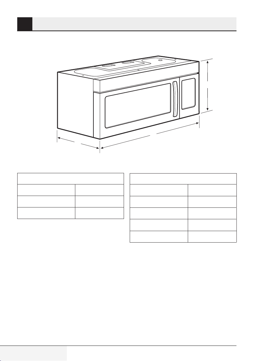
Product Dimensions
A-Height 15.7 (39.9 cm)
B-Width 29.9 (75.9 cm)
C-Depth 15.0 (38.1 cm)
6 / 63 EN
Over The Range Convection Microwave Oven / Installation Manual
Cutout Dimensions
Height (Min.) 16.75 (42.5 cm)
Height (Max.) 17.0 (43.2 cm)
Width (Min.) 30.0 (76.2 cm)
Depth (Min.) 12.0 (30.5 cm)
Depth (Max.) 13.0 (33.0 cm)
Page 7
Mounting space
3
[12“ (30.5 cm) min.]
3
16
⁄4 “ (42.5 cm)
30
“ (76.2 cm)
66 (167.6 cm)
or More from
the Floor to the
Top of the
Microwave
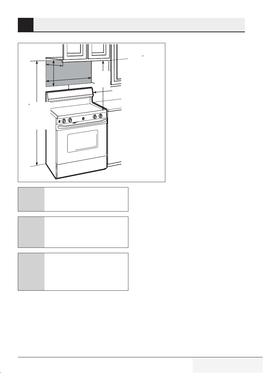
The space between the cabinets
must be 30“ (76.2 cm)wide and free
C
of obstructions.
“ (5.1 cm)
2
“
30
(76.2 cm)
min.
Backsplash
Bottom Edge of
Cabinet Needs to
(76.2 cm)
be 30
or More from the
Cooking Surface
If you are going to vent your microwave oven to the outside, see Hood
C
C
Exhaust Section for exhaust duct
preparation.
When installing the microwave oven
beneath smooth, flat cabinets, be
careful to follow the instructions on
the top cabinet template for power
cord clearance.
Over The Range Convection Microwave Oven / Installation Manual
7 / 63 EN
Page 8
External exhaust
4
4.1 Installing hood exhaust
Read these instructions only if you
plan to vent your exhaust to the out-
C
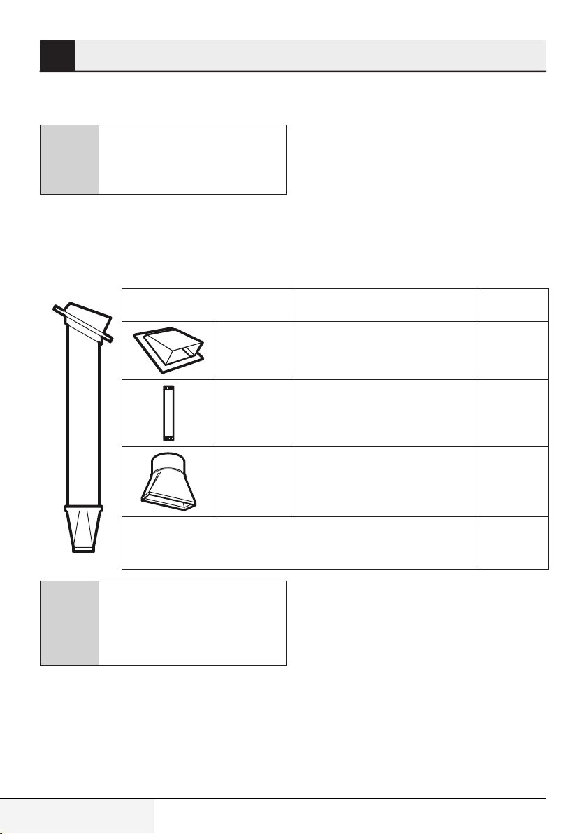
4.1.1 Outside top exhaust
(example only)
The following chart describes an example of one
possible ductwork installation.
side. If you plan to recirculate the air
back into the room, proceed to title 5
C
Duct pieces Equivalent
Roof Cap 24 Ft. (7.3 m) x (1) = 24 Ft. (7.3 m)
12 Ft. (3.6 m)
Straight Duct
(6”/15.2 cm
Round)
Rectangular-toRound
Transition Adaptor*
Equivalent lengths of duct pieces are based on actual tests
and reflect requirements for good venting performance
with any vent hood.
If a rectangular-to-round transition
adaptor is used, the bottom corners
of the damper will have to be cut to
fit, using the tin snips, in order to allow free movement of the damper.
Length
12 Ft. (3.6 m) x (1) = 12 Ft. (3.6 m)
5 Ft. (1.5 m) x (1) = 5 Ft. (1.5 m)
Number
x
used
Total Length = 41 Ft. (12.5 m)
Equivalent
=
Length
8 / 63 EN
Over The Range Convection Microwave Oven / Installation Manual
Page 9
External exhaust
4
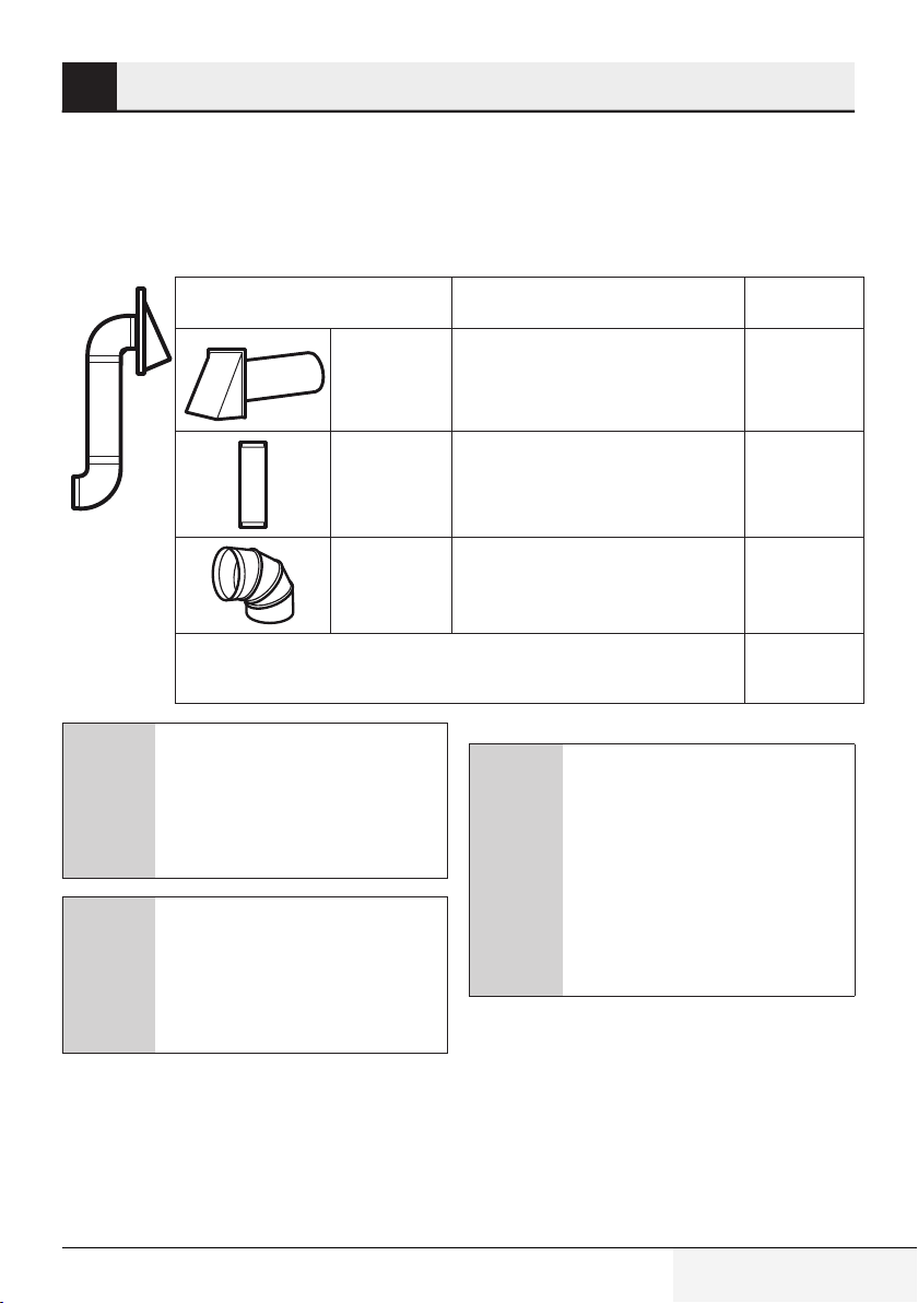
4.1.2 Outside back exhaust
(example only)
The following chart describes an example of one
possible ductwork installation.
C
C
Duct pieces Equivalent
Wall Cap 40 Ft. (12.2 m) x (1) = 40 Ft. (12.2 m)
3 Ft. Straight
Duct (31⁄4” x
10”/8.2 x 25.4
cm Rectangular)
90° Elbow 10 Ft. (3 m) x (2) = 20 Ft. (3 m)
Equivalent lengths of duct pieces are based on actual tests
and reflect requirements for good venting performance with
any vent hood.
For back exhaust, care should be taken to align exhaust with space between studs, or wall should be prepared at the time it is constructed by
leaving enough space between the
wall studs to accommodate exhaust.
Length
3 Ft. (0.9 m) x (1) = 3 Ft. (0.9 m)
C
If you need to install ducts, note
that the total duct length of 3
10” (8.2 x 25.4 cm) rectangular or
6” (15.2 cm) diameter round duct
should not exceed 120 equivalent
feet (36.5 m).
1⁄4
” x
4.1.3 Exhaust connection
The exhaust adaptor has been designed to mate
with a standard 3
gular duct. If a round duct is required, a rectangular-to-round transition adaptor must be used. Do
not use less than a 6” 6” (15.2 cm) diameter duct.
Number
x
used
Total Length = 63 Ft. (19.2 m)
Outside ventilation requires a HOOD
EXHAUST DUCK. Read the following
carefully. It is important that venting
be installed using the most direct
route and with as few elbows as
possible. This ensures clear venting of exhaust and helps prevent
blockages. Also, make sure dampers
swing freely and nothing is blocking
the ducts.
1⁄4
” x 10” (8.2 x 25.4 cm) rectan-
Equivalent
=
Length
Over The Range Convection Microwave Oven / Installation Manual
9 / 63 EN
Page 10
External exhaust
4
4.1.4 Maximum duct length
For satisfactory air movement, the total duct
length of 3
1⁄4
” x 10” (8.2 x 25.4 cm) rectangular or
6” (15.2 cm) diameter round duct should not exceed 120 equivalent feet (36.5 m).
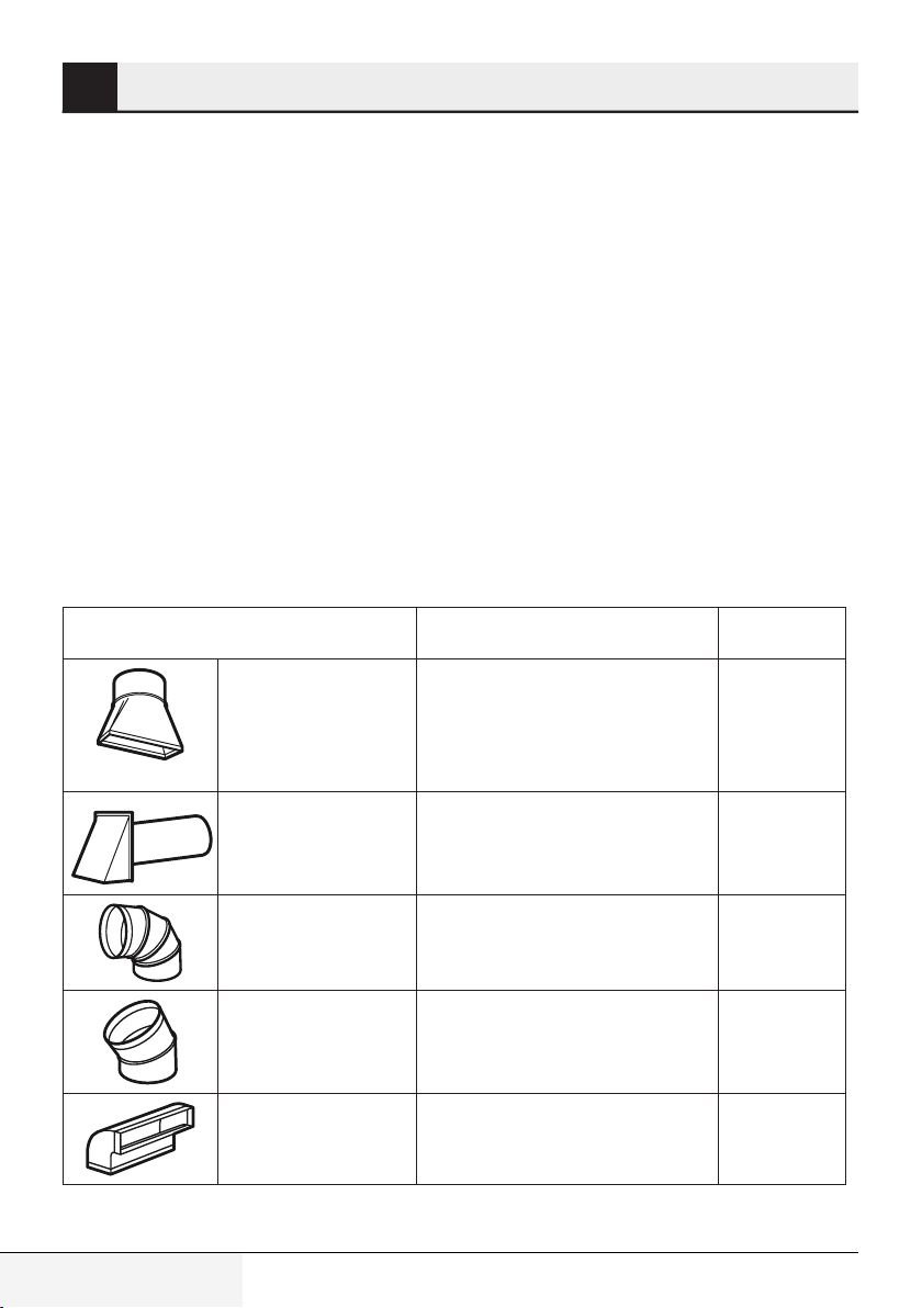
4.1.5 Elbows, transitions, wall
and roof caps, etc.,
Present additional resistance to airflow and are
equivalent to a section of straight duct which is
longer than their actual physical size. When calculating the total duct length, add the equivalent
lengths of all transitions and adaptors plus the
length of all straight duct sections. The chart below shows you how to calculate total equivalent
ductwork length using the approximate feet of
equivalent length of some typical ducts.
Duct pieces Equivalent
Rectangular-to-Round
Transition Adaptor*
Wall Cap 40 Ft. (12.2 m) x ( ) = Ft. or m
Length
5 Ft. (1.5 m) x ( ) = Ft. or m
x
Number
used
Equivalent
=
Length
10 / 63 EN
90° Elbow 10 Ft. (3 m) x ( ) = Ft. or m
45° Elbow 45° Elbow x ( ) = Ft. or m
90° Elbow 25 Ft. (7.6 m) x ( ) = Ft. or m
Over The Range Convection Microwave Oven / Installation Manual
Page 11
External exhaust
4
45° Elbow 5 Ft. (1.5 m)
Roof Cap 24 Ft. (7.3 m)
Straight Duct 6“ (15.2 cm)
Round or
1⁄4
3
” x 10” (8.2 x 25.4
cm) rectangula
If a rectangular-to-round transition
adaptor is used, the bottom corners
of the damper will have to be cut to
C
C
fit, using the tin snips, in order to allow free movement of the damper.
For back exhaust, care should be taken to align exhaust with space between studs, or wall should be prepared at the time it is constructed by
leaving enough space between the
wall studs to accommodate exhaust.
4.2 Damage – shipment /
installation
• If the unit is damaged in shipment, return the
unit tı the store in which it was bought for repair
or replacement.
• If the unit is damaged by the customer, repair
or replacement is the responsibility of the
customer.
• If the unit is damaged by the installer /if other
than the customer), repair or replacement must
be made by arrangement between customer
and installer.
x ( ) = Ft. or m
x ( ) = Ft. or m
1 Ft. (0.3 m)
x ( ) = Ft. or m
Total Ductwork = Ft. or m
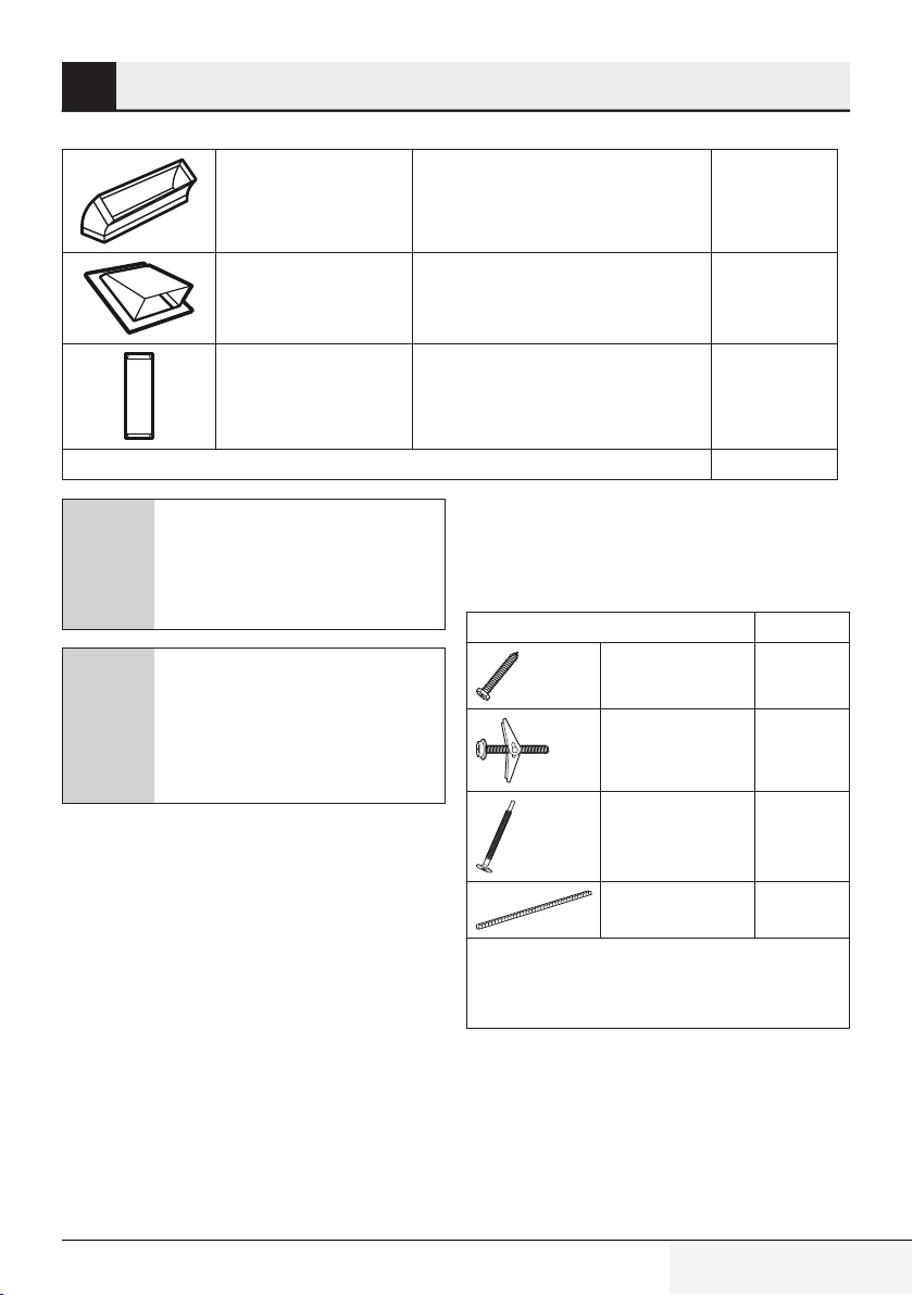
4.3 Parts included
4.3.1 Hardware packet
Part Quantity
Wood Screws
(1⁄4“ x 2“)
Toggle Bolts (and
wing nuts) (3⁄16“
x 3“)
Self-Aligning Machine
Screws
(1⁄4“-28 x 31⁄4“)
Nylon Grommet
(for metal cabinets)
You will find the installation hardware contained in a packet
with the unit. Check to make sure you have all these parts.
NOTE: Some extra parts are included.
2
2
3
1
Over The Range Convection Microwave Oven / Installation Manual
11 / 63 EN
Page 12
External exhaust
4
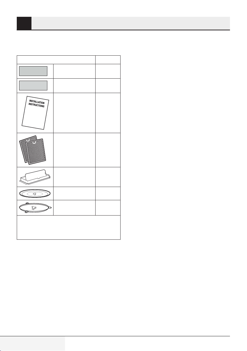
4.3.2 Additional parts
Part Quantity
To p C abinet
Template and
Rear Wall Template 1
1
Installation
Instructions
Separately Packed
Grease Filters
Exhaust adaptor 1
Glass tray 1
Turntable ring 1
You will find the installation hardware contained in a packet
with the unit. Check to make sure you have all these parts.
NOTE: Some extra parts are included.
1
2
12 / 63 EN
Over The Range Convection Microwave Oven / Installation Manual
Page 13
External exhaust
bottom
only)
4
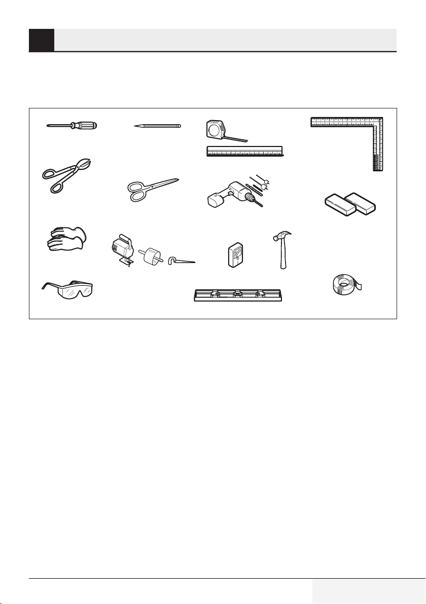
4.4 Tools and materials
needed
#1Phillips screwdriver
Tin snips (for cutting
damper, if required)
Gloves
Scissors
(to cut template, if necessary)
Pencil
Saw (saber, hole or keyhole)
Ruler or tape measure and
straight edge
Electric drill with
drill bits
Stud nderor
3
⁄16“,1⁄2“ and5⁄8“
Hammer (optional)
Carpenter square
(optional)
Filler blocks or scrap
wood pieces, if needed
for top cabinet spacing
(used on recessed
cabinet installations
Safety goggles
Level
Over The Range Convection Microwave Oven / Installation Manual
Duct and masking tape
13 / 63 EN
Page 14
Installation
5
5.1 Placement of the
mounting plate
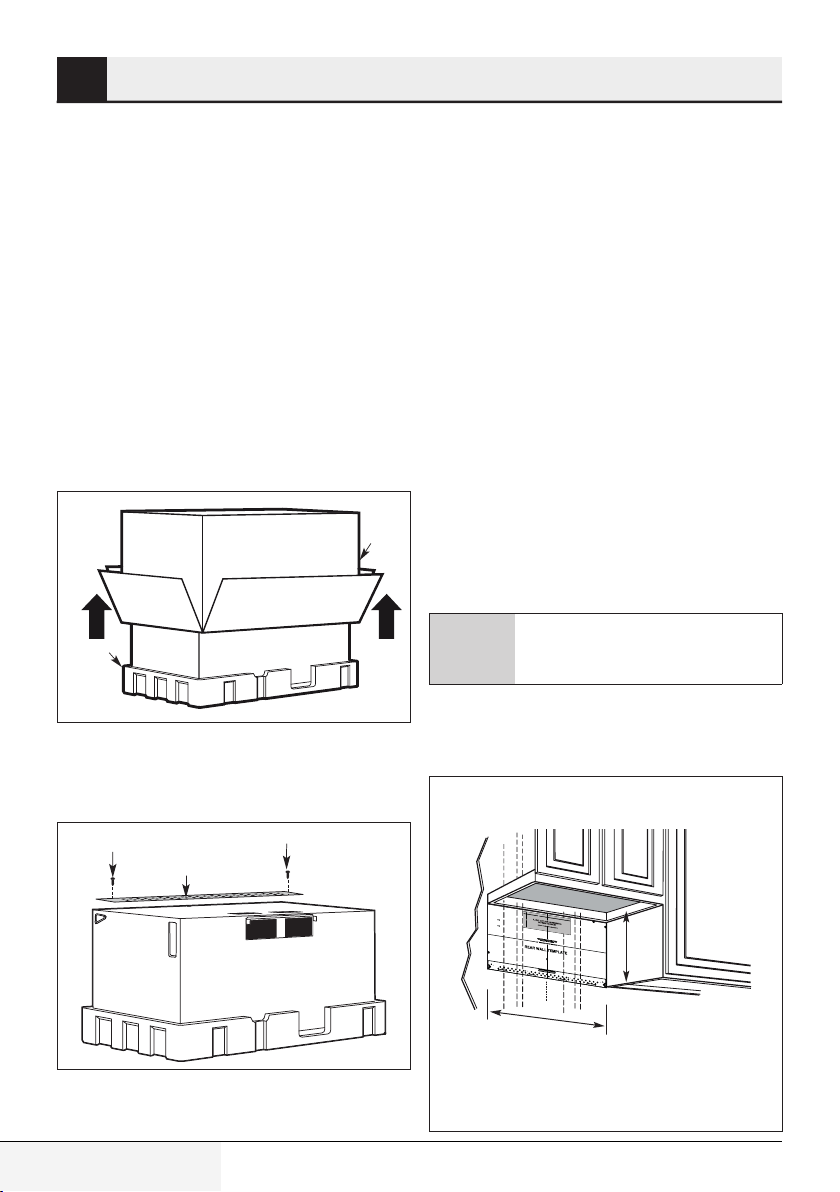
5.1.1 Removing the microwave
oven from the carton/ removing
the mounting plate
1. Remove the installation instructions, filters,
glass tray and the small hardware bag. Do not
remove the Styrofoam protecting the front of
the oven.
2. Fold back all 4 carton flaps fully against carton
sides. Then carefully roll the oven and carton
over onto the top side. The oven should be
resting in the Styrofoam.
Carton
Styrofoam
3. Pull the carton up and off the oven.
4. Cut the middle of the outer protective plastic
bag to remove the mounting plate
Screws
Mounting Plate
Screws
5. Remove the screws from the mounting plate.
This plate will be used as the rear wall template
and for mounting. Reinstall the screws into the
holes where they were removed.
5.1.2 Finding the wall studs
1. Find the studs, using one of the following
methods:
• Stud finder – a magnetic device which locates
nails.
• Use a hammer to tap lightly across the mounting
surface to find a solid sound. This will indicate a
stud location.
2. After locating the stud(s), find the center by
probing the wall with a small nail to find the
edges of the stud. Then place a mark halfway
between the edges. The center of any adjacent
studs should be 16“ (40.6 cm) or 24“ (61 cm)
from this mark.
3. Draw a line down the center of the studs.
WARNING:
The microwave must
be connected to at least one wall
A
stud.
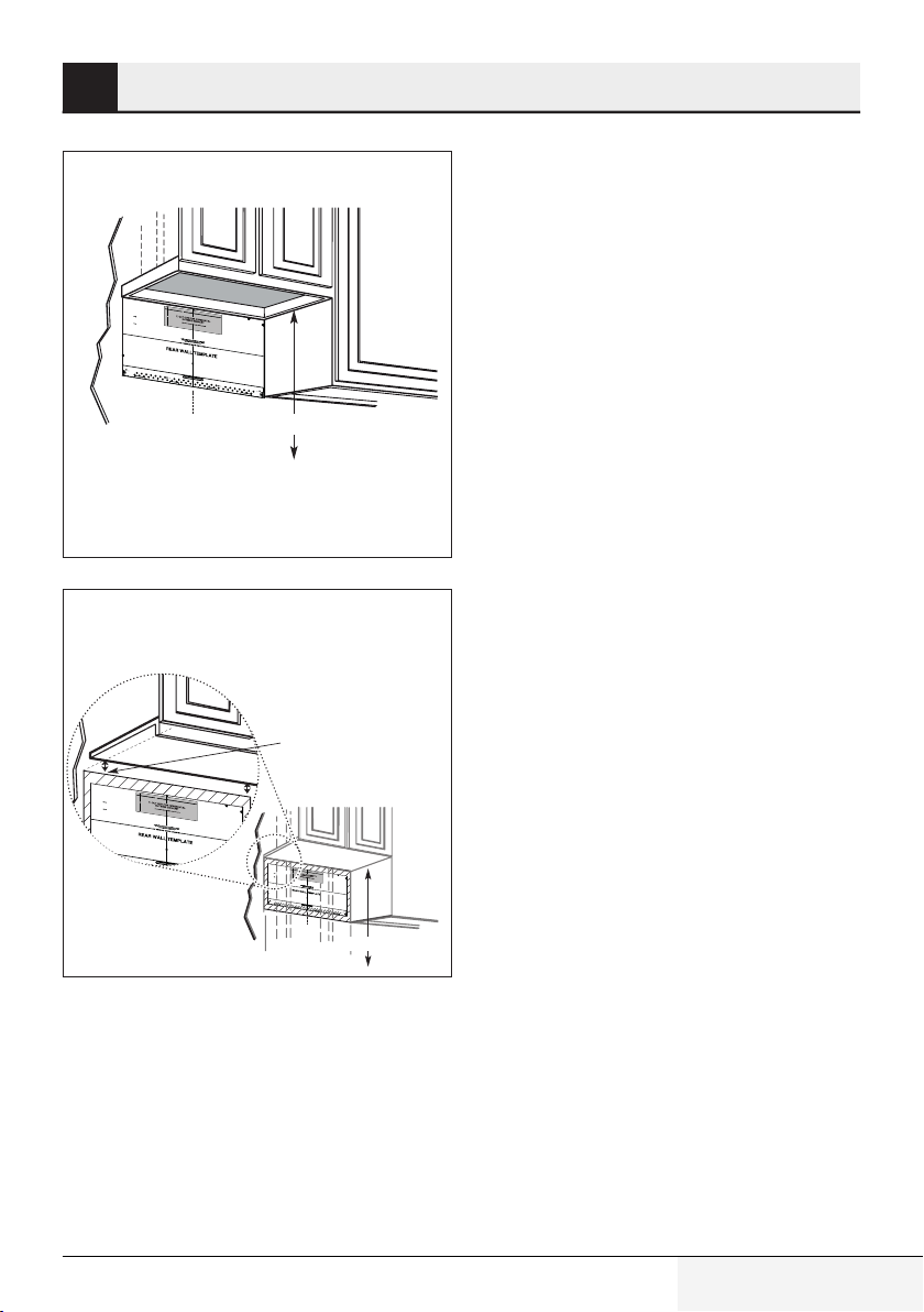
5.1.3 Determining wall plate
location under your cabinet
Plate position—beneath at bottom
cabinet
14 / 63 EN
N
OT
E:
I
T
I
S
V
ER
REA
Y
D
I
M
A
P
ND
OR
F
T
O
AN
I
N
L
LOWTH
T
T
TO
H
E
I
N
ST
ED
A
BE
L
I
R
L
EC
AT
FOR
I
T
ON
I
O
E
NS
P
I
N
R
S
OC
T
R
RU
E
E
AR
E
C
D
TIONS
I
W
N
GWI
A
LL
T
T
E
H
3/
MP
T
8"
T
his
T
H
LA
O
Rear
I
S
ED
T
GE
E.
Wal
l
T
mo
e
m
u
p
n
la
t
i
n
te
gpl
se
at
r
ve
e
12"
a
st
outl
n
o
d
e
p
t
o
t.
os
l
o
itio
c
a
n
t
e
th
t
h
e
e
1. Useale
b
h
o
o
t
t
rizon
o
m
ta
l
v
e
e
xh
l
t
o
a
c
u
s
hec
a
t
c
c
k
u
r
t
a
h
t
a
ely
t
th
.
e
t
2
e
.Lo
m
p
la
c
a
t
e
t
e
i
s
a
n
p
dmar
o
s
i
t
i
o
n
k
r
i
ed
gh
a
t
t
lea
si
de
st
on
o
f
e
t
h
st
e
ce
u
d
n
4"
o
te
n
r
th
lin
e
e
It
l
.
ef
i
s
t
imp
or
o
scre
rt
a
n
w
t
to
mo
u
un
s
e
te
a
d
tle
o
fi
f
rmly
a
th
s
t
e
o
i
micr
n
n
e
a
wo
st
o
w
u
o
av
d
d
to
lo
e
. M
c
s
a
u
t
a
pp
ion
rk
ort
two
s f
or t
t
h
e
ad
h
weig
e
di
3
s
ti
.D
up
on
h
ril
t
p
a
l
l, e
l
i
ho
e
d
v
l
to
e
e
n
s
g
l
g
y
in
le b
s
t
p
h
a
e
o
a
ced
lt
m
s
s.
a
tud
r
k
e
, d
d
ril
loca
la
ti
3
o
/
1
n
t
hat
6
s.W
" h
d
o
h
o
l
e
ere th
n
fo
ot
r wo
l
i
neupwithast
er
od
e
t
o
is
s
gg
cr
l
e
e
ws. Fo
bo
lt
s
u
.
d,
r h
d
ole
r
ill 5
s
/8
"
ho
DO
l
e
s
NOT
fo
r
AT
I
N
T
ST
HIST
AL
L
I
T
ME.
HEMOUNT
4
.
Re
mo
v
I
N
e th
G P
e
LA
te
5
.Re
m
T
p
E
la
v
te
i
e
w
fr
om the
t
h
e
I
n
st
r
a
i
e
n
l
l
a
st
a
r
t
a
io
wa
ll
n
a
l
ti
Ins
l
.
o
n
t
ru
s
i
tu
c
tion
a
ti
o
b
n.
o
ok
f
o
r
you
r
Da
r
l
e
vue
lta
a
la
v
e
h
rs
oja
ió
n
par
e
n
a
E
c
sp
on
añ
s
u
ol
ltar
.
la
Loc
at
e
a
nd m
ar
k
m
h
olest
o
un
ti
ng
o
a
plat
li
gn
e.
w
ith
IM
ho
PORTA
les
int
NT:
he
LOC
A
T
EA
T
LEA
S
T
H
T
E
O
N
CENT
EST
ER
UDONEI
LI
N
M
E.
ARK
T
H
T
ER
H
EL
SI
DE
OC
A
O
SP
T
F
I
ON
ACED
F
O
TOGGL
R
2
A
D
D
AR
E
IT
BO
E
I
O
A.
LTSIN
N
A
L,EVE
TH
NLY
E
MOU
NT
I
N
G
P
L
AT
E
T
r
imth
er
ear
w
al
l
te
mpl
a
t
e
al
o
ngt
h
e
d
ott
ed
l
i
n
e.
A
t
T
r
im t
he
r
earwa
l
l
tem
pl
atea
l
o
n
g
t
h
e
d
o
t
te
dl
i
n
e.
16-1/2
Loc
at
ea
nd
m
ark
m
ho
o
les
u
nt
t
i
o alig
ng
p
la
n
t
e.
with
I
M
PO
R
T
A
N
T:
LOC
A
T
EA
T
LEA
S
THE
T
O
N
CE
ESTUD
NT
E
RLI
N
M
E
A
.
R
K
T
HE
LO
CAT
S
PA
I
ON
CED
F
OR
TOGG
2
A
LE
AREA.
B
OLT
S
I
N
T
H
C
L
e
l
a
s
t
3
0
ʺ
ʺ
holesint
he
ON
E
I
T
H
ER
S
I
D
E
OF
DD
I
T
I
O
NAL,
E
V
ENLY
E
M
OU
NT
I
NG P
LAT
E
Draw a vertical line on the wall at the center of the
30
ʺ wide space. Tape the Rear Wall Template
onto the wall matching the centerline and touching
the bottom of the cabinet.
Over The Range Convection Microwave Oven / Installation Manual
Page 15
Installation
3/8
"
TO EDGE
N
O
TE:
I
T
IS VER
YIMPOR
T
ANT TO
R
EAD A
N
DFO
L
LO
W
T
HE D
IR
ECTI
O
N
S
I
N
TH
E
IN
ST
ALL
AT
IONIN
STR
U
CTI
O
N
S
BEFO
R
E
PR
O
C
EED
IN
G
W
ITH
T
H
IS
R
EAR
W
ALL TE
MPL
AT
E.
Th
is
R
ea
r
W
a
ll Te
mp
la
t
e s
e
r
v
es
to po
s
it
io
nth
e
b
o
t
to
m
mo
untin
g
pla
t
e
and
t
o l
ocat
e
the h
o
r
iz
o
ntal e
x
h
aus
t
ou
tlet.
1.
U
s
e
alev
el to
c
hec
k
th
a
t
th
e template isp
ositio
n
ed
a
cc
u
rat
ely
.
2
.L
o
c
a
te a
nd
mar
k
a
t le
as
t
o
n
e
s
t
ud o
n
t
he le
f
t
o
r
r
ig
ht
s
id
e
o
f
th
e c
e
n
te
rl
in
e.
It
is
i
mp
o
rta
n
t t
o
u
s
e a
t le
ast
o
n
e
w
oo
d
s
c
r
ew
mo
un
t
e
d
f
irmly
in a
stu
d
to
s
uppor
t t
he we
ight
of
the micr
o
wa
v
e
.
Ma
rk
t
wo a
dd
itiona
l,
e
venl
y
sp
a
ce
d
loc
a
tio
ns
f
or
th
e s
upp
lie
d t
og
g
le
b
olts.
3.
D
rill h
ole
s
in
t
he
ma
r
k
ed loc
a
tio
n
s.
W
her
e th
e
r
e is
a
s
tu
d, d
rill
a
3
/1
6"
holefo
r
wo
od
s
cr
ews
. Fo
r ho
les
th
a
t do no
t lin
e
u
p
w
ith
a
s
t
u
d,
d
r
ill 5
/
8" h
o
le
s fo
r
tog
g
le
b
olts.
D
O
N
OT
INSTA
L
L
TH
E
MO
U
N
TIN
G
P
L
ATE
AT
THIS TIME
.
4
.
R
e
m
o
v
e
th
e te
mp
la
te fr
om
th
e
re
a
r w
all.
5.
R
e
v
iew
t
he
In
s
t
all
atio
n
Ins
tru
c
t
ionbo
o
k fo
r
your
in
stallation
s
itu
a
tio
n.
Lo
cate
and
ma
rk
h
ol
es t
o al
i
g
n w
it
h
hol
e
s
i
n th
e
mountin
g
pl
a
te
.
I
M
POR
T
AN
T
:
LOC
A
TE ATLEAST
ONE STU
D
ON
EITH
ER
SI
DE
OF
THE C
EN
T
ER
LIN
E.
MAR
KTH
E
LOCATIO
N
FO
R
2 AD
D
IT
I
ONAL
,
EVEN
L
Y
SPAC
ED
TOG
GLE
BO
L
TS
I
N
TH
E
M
OU
N
T
I
N
G PLATE
AREA
.
Locatean
d
ma
rk
hol
es t
o alig
n wi
t
hhol
e
s
in the
moun
tin
g pla
t
e
.
IMPO
RT
ANT:
LOC
AT
E AT
LEASTON
E ST
U
D
ON EI
T
H
ERSID
E
O
F
TH
E
C
EN
TE
R
LIN
E.
MAR
K
T
HE
LO
C
ATIO
N
FOR
2AD
D
I
TION
AL, EVENL
Y
SPA
C
E
D
TO
G
GLE
BO
LT
S
I
NTH
EMO
U
N
TIN
AR
EA.
Trim
the
rear
wall
t
em
p
lat
e
a
long
the
d
otted
li
ne.
Trim
th
e
r
ear
wal
l
tem
pl
atea
l
ong
th
edottedli
ne.
12
"
4"
Darle
vu
el
t
a
a
lah
o
jap
a
ra
c
o
nsult
a
r
la
v
e
rsi
ón
e
n
E
s
p
añ
o
l.
5
Plate position—beneath framed recessed
cabinet bottom
NO
T
E
:I
TIS
VER
R
EA
Y
D
IMPO
A
ND
R
FO
TA
I
N
NT
L
LOW
TH
T
O
EI
T
NS
HEDIRE
T
ALLA
BE
F
CT
TION
O
R
IO
E
NS
I
P
NS
RO
T
REARWA
C
R
E
U
ED
CTI
I
N
ONS
GW
L
LTEM
I
T
H
T
3/
hi
T
8
P
"
sR
HIS
TO
LA
e
E
a
TE
D
r
G
Wa
E
.
l
lTe
mo
m
u
p
n
l
t
a
ingpla
t
e
s
erv
t
ean
e
s
12"
o
to
u
d
tl
p
e
tol
o
t
.
si
o
ti
c
o
at
n
e
theb
t
h
eho
1
ot
.
U
t
r
o
i
s
z
m
e
ont
a
a
l
e
l
ve
e
x
l
h
t
o
a
u
che
st
a
cc
ck t
u
r
h
at
a
ely.
tt
h
e
t
e
2.
mp
L
oc
la
t
a
e
t
e
i
s
a
p
ndmark
osi
tion
ri
ed
g
a
h
t
t
l
e
s
a
i
d
st
e
o
o
n
f
e
t
h
stu
e
c
d
e
nt
on
4"
e
r
t
h
l
in
e le
e.
It
i
f
s
t o
i
mpo
r
sc
rta
r
e
n
w
t
t
mou
o
usea
n
te
d
t
l
e
fi
o
r
a
f
ml
sto
t
h
y
e
in
n
micr
ew
a
stu
o
o
w
o
d
d
a
v
t
osuppor
e
l
o
.
c
M
at
a
io
rk
n
s for
t
t
w
t
o ad
he w
th
e
d
e
it
3
i
supplie
ght
i
.
on
D
a
ril
l
,
l
h
e
dtoggle
ol
v
e
e
nl
s
y
i
n
sp
th
b
a
e
o
ce
astu
l
m
t
s.
d
a
r
ke
d
,dri
d
lo
l
l
ca
a
t
3
io
/
1
n
th
s. Wh
6"
at
ho
do
l
e
e
n
r
for
e
o
tline
t
h
w
e
oo
rei
to
u
dsc
s
p
g
w
gl
r
it
e
e
h
w
bol
a
s.
st
Forh
t
s.
u
d,dri
o
l
e
l
l
s
5
/
8
" h
o
D
le
O
sf
N
o
O
r
T
AT
I
N
TH
S
TA
I
S TI
L
L
TH
M
E
EM
.
4
.R
OUN
e
mo
T
I
ve
N
GPL
th
et
AT
e
5
mp
.
Re
E
lat
vie
efrom
w
the
t
I
h
n
e
sta
re
in
l
a
l
at
s
r
t
a
i
wa
o
l
l
nI
a
l
ti
l.
nstr
o
n si
u
ct
t
uat
i
o
n
i
o
b
n
o
.
o
k
f
o
ryo
u
r
Da
rl
e
vu
e
lta
al
ve
aho
r
s
ión
ja
p
e
a
nE
ra
c
spa
o
n
s
ñ
ult
ol
.
a
r
la
Loc
a
t
e
and
mark
holest
m
o
u
n
ti
o
ng
a
l
pl
i
g
ate.
n
wi
t
h h
IMP
ole
ORT
s
in
A
t
he
NT:
L
O
C
A
TEAT
LE
A
ST
T
HE
ONE
CENT
S
T
ERLIN
UDON
MA
E.
E
R
ITH
K
E
THELOC
R
S
I
D
E
OF
A
S
T
P
I
ON
A
CE
F
D
OR
T
O
2
GGL
A
DDI
AR
E
T
BO
E
ION
A.
LTSIN
AL
,
E
VE
TH
NL
EMOUNT
Y
ING
P
L
ATE
Tri
mt
herea
r
w
a
ll
t
em
p
l
atea
l
o
n
g
t
he
do
tt
e
d
l
i
ne.
Draw a vertical line onthe wall at the center of the
ʺ space.
30
Tape the Rear Wall Template onto the wall
matching the centerline and touching the bottom
cabinet frame.
C
L
T
r
i
mt
h
e
rea
rwa
l
l
t
e
mp
l
ate
alon
g
t
h
edo
t
te
d
lin
e
.
Loc
ate
a
nd
ma
r
k
h
moun
oles
t
toa
in
g
l
p
i
g
l
a
n
te.
wit
h
IMP
ho
le
O
s
RTANT:
in
t
h
e
L
OCA
TE
A
T
L
EAS
T
T
H
E
O
N
C
E
E
N
S
TERLIN
TUDON
MA
E
.
EI
RKT
THE
HE
R
S
L
I
D
O
E
C
O
A
SP
T
F
I
O
A
C
N
E
F
DTOG
O
R2
A
GLEB
DDI
A
RE
T
I
ONA
O
A.
LT
S I
L,E
N
V
TH
ENL
E
MO
Y
UNTING
P
L
ATE
33ʺ to Cooktop
Plate position—beneath recessed bottom
cabinet with front overhang
Draw a line on the
back wall equal to the
depth of the front
overhang.
The microwave must be level.
Use a level to make sure the cabinet bottom is level.
If the cabinets have a front overhang only, with
no back or side frame, install the mounting plate
down the same distance as the front overhang
depth. This will keep the microwave level.
1. Measure the inside depth of the front overhang.
2. Draw a horizontal line on the back wall an equal
distance below the cabinet bottom as the inside
depth of the front overhang.
3. For this type of installation with front overhang
only, align the mounting tabs with this
horizontal line, not touching the cabinet bottom
as described in subtitle 5.1.4.
NOT
E
:
I
T
I
S
V
RE
E
R
ADA
Y
IMPOR
N
D
FOLL
T
IN
A
N
T
T
OW
HE
TO
INS
T
H
E
T
AL
D
BE
IR
LAT
F
E
O
CT
R
ION
E
I
ON
P
IN
ROC
S
S
R
T
E
R
EE
AR
U
CT
DING
WA
IONS
L
L T
W
ITH
E
Thi
M
T
s
P
R
H
L
e
A
a
IS
r
T
W
3/8
E
all
.
"T
m
T
O
e
o
un
mp
E
D
tin
G
l
a
E
t
g
e
pla
s
e
r
t
e
v
e
o
a
s
u
nd
t
to
l
e
t
t.
p
o
o
lo
s
1
itio
c
2
at
"
n
e
t
t
h
h
1
e
e
.
b
U
h
o
o
s
tt
r
e
iz
o
a
m
o
nt
le
v
a
e
l
e
l
t
x
o
h
ch
au
a
c
e
st
c
c
ur
k
a
t
h
tely
a
tt
.
h
e
2
.
t
e
L
m
o
c
plat
a
t
e
eisp
a
n
d
o
m
s
a
it
r
ri
ion
ka
g
h
e
t
t
d
le
si
ast
d
e
o
o
f
n
t
e
h
e
s
t
ce
ud
nt
o
e
n
r
l
t
i
n
h
I
e
e
4
t
.
is
"
le
f
impo
t
o
s
r
c
r
rew
t
a
n
t
m
t
o
o
u
use
n
t
e
d
a
o
t
f
f
i
le
r
t
m
h
ast
e
ly
m
o
in
n
icr
a
e
owa
s
w
t
ood
u
d
v
loca
e
t
o
.
M
s
t
io
up
ar
ns
p
k
o
t
fo
wo
r
t
r
t
h
t
a
h
ew
d
es
3
d
.
iti
e
Dril
u
i
ona
pp
g
h
l
lie
t
ho
l,
d
e
les
v
to
e
g
nly
in
gl
eb
th
s
pa
e
a
o
m
s
c
l
ts.
t
e
a
u
d
r
d
k
,
e
Trim
dr
dlo
i
ll
c
a
a
3
th
t
i
/
o
t
1
ha
n
6
e
s.
"
t
h
do
r
W
o
ea
le
h
n
er
o
fo
r
t
et
wa
r
li
n
w
h
e
o
e
t
o
r
u
o
l
e
l
ds
pw
g
is
g
te
le
c
it
re
m
h
bo
ws
a
p
lt
s
s
.F
la
t
.
u
o
d
te
r
,
d
h
ril
al
ole
l
o
5
s
/
ng th
8
"
h
DO
o
l
es
N
e
O
f
o
AT
4
.R
5
.
Da
v
e
Lo
mou
IMP
L
O
T
MA
S
A
T
rim
th
e
r
e
a
r
wa
d
T
r
o
IN
T
tte
S
HI
T
S
T
I
M
E
e
m
o
v
et
he
R
ev
i
e
w
the
i
n
s
t
a
l
lat
io
n
s
r
le
v
ue
lt
a
a
r
s
i
ó
nen
E
s
c
a
t
ea
nd
n
t
i
ng
p
O
R
TA
N
CAT
E
AT
HE
CE
N
T
R
KT
H
E
P
AC
ED
T
R
E
A.
l
l
te
mp
l
d
A
L
L
l
in
T
H
e
.
E
.
M
OU
N
T
I
N
G
P
t
e
L
m
A
pla
T
E
t
e
f
ro
m
I
t
n
h
s
e
ta
r
lla
e
a
t
r
i
o
w
n
a
I
l
n
l.
s
tr
i
u
t
u
c
a
ti
o
t
i
o
n
n.
b
oo
k
f
o
r
y
o
ur
la
h
oja
para
c
p
on
a
ñ
su
o
l.
l
ta
r
la
ma
r
kho
l
es
to
a
lig
l
a
t
n
e
.
w
i
th
h
o
le
si
n
th
T
:
e
L
E
A
S
T
O
NE
S
TUDO
E
R
L
IN
E
N
.
E
I
T
H
E
R
L
S
O
ID
C
E
AT
OF
ION
F
OR
O
GG
2
A
L
D
E
DI
B
T
OL
I
ON
T
SI
A
L
,
NTH
E
V
E
E
N
MO
L
Y
UN
T
IN
G
P
L
A
TE
at
e
alo
n
gth
ed
o
tte
d line
.
Lo
ca
te
a
n
d
ma
rk
mou
hol
e
nt
s
in
toa
g
p
li
l
a
g
t
n wi
e
.
IMP
t
h
h
O
o
l
R
e
s
T
A
i
n
N
t
T
h
e
:
L
O
C
A
TE A
T
L
EA
T
ST
H
EC
ON
E
E
N
ST
T
E
U
R
D
L
IN
O
MAR
E
NE
.
K
IT
T
HE
H
E
R
LO
SID
C
S
E O
A
P
T
AC
ION
F
E
FOR
D
T
O
2A
GG
A
LE
DDIT
R
B
EA
OL
I
ON
.
T
S
A
L
INT
,
E
V
H
E
E
NLY
M
O
U
NT
IN
G
P
L
AT
E
C
L
33" to Cooktop
Your cabinets may have decorative trim that interferes with the microwave installation. Remove the
decorative trim to install the microwave properly
and to make it level
Over The Range Convection Microwave Oven / Installation Manual
15 / 63 EN
Page 16
Installation
5
NOTE: IT IS VERY IMPORTANT TO
READ AND FOLLOW THE DI
IN THE INSTALLATION INSTRUCTIONS
BEFORE PROCEEDI
REAR WALL TEMPLATE.
This Rear Wal
mounting plate and to locate
outlet.
1. Use a level to check th
accurately.
2. Locate and ma
right side of the centerlin
It is important to use at least one wood
screw mounted firmly in a stud to s
of the microwave. Mark two add
locations for the supplied toggle bolts.
3. Drill holes in the marked locatio
a stud, drill a 3/16" hole for
that do not line up with a st
toggle bolts.
DO NOT INSTALL THE M
AT THIS TIME.
4. Remove the tem
5. Review the Installation Instru
installation situation.
Darle vuelta a la hoja para consultar la
versión en Español.
Locate and mark
mounting plat
IMPORTANT:
LOCATE
THE CENTERLINE.
MARK THE LOCATION FOR 2
SPACED
AREA.
Hole B
AT LEAST ONE
TOGGLE BOLTS IN
l Template serves t
at the template is positioned
rk at least one stud on the left or
plate from the rear wall.
holes to align with h
e.
NG WITH
the horizontal exhaust
e.
wood screws. For hole
ud, drill 5/8" holes for
ction book for your
RECTIONS
o position the bottom
upport the weight
itional, evenly spaced
ns. Where there is
OUNTING PLATE
STUD ON EITHER SIDE OF
ADDITIONAL, EVENLY
THE MOUNTING PLATE
3/8" TO EDGE
THIS
12"
4"
s
oles in the
Centerline
notches
Trim the rear
wall template al
Locate and mark
holes to align with hol
mounting plat
e.
IMPORTANT:
LOCATE
AT LEAST ONE
STUD ON EITHER SIDE OF
THE CENTERLINE.
MARK THE LOCATION FOR 2
SPACED
TOGGLE BOLTS IN
AREA.
Draw a Vertical Line
on Wall from Center
of Top Cabinet
ADDITIONAL, EVENLY
THE MOUNTING PLATE
ong the dotted
line.
es in the
Horizontal Line
Area E
C
Hole A
Draw a Horizontal line on wall from
L
bottom of “Rear Wall Template”.
Wear gloves to avoid cutting fingers
A
on sharp edges.
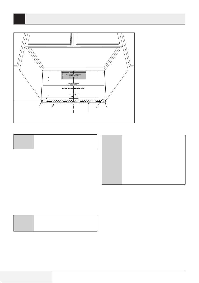
5.1.4 Aligning the wall plate
1. Draw a Vertical line on the wall at the center of
the 30” wide space.
2. Draw a Horizontal line on the wall at the bottom
of “Rear Wall Template”.
3. Drill 5/8” holes for toggle bolts on 2 locations
(Hole A, Hole B) but if the location of hole is
same as that of stud, drill a 3/16” hole for wood
screw. In other words, toggle bolt can not be
used to the location of stud.
DO NOT MOUNT THE PLATE AT THIS
C
TIME.
Horizontal Line
C
Holes A and B are inside area E. If
both of A and B are not in a stud,
find a stud somewhere in area E and
draw a forth circle to line up with the
stud. It is important to use at least
one wood screw mounted firmly in
a stud to support the weight of the
microwave. Set the mounting plate
aside.
16 / 63 EN
Over The Range Convection Microwave Oven / Installation Manual
Page 17
Installation
5
5.2 Installation types (choose
A, B or C)
this microwave oven is designed for adaptation to
the following three types of ventilation:
• Outside Top Exhaust (Vertical Duct Type A)
Adaptor in Place for
Outside Top Exhaust
• Outside Back Exhaust (Horizontal Duct Type B)
Adaptor Must Be
Moved to the Back for
Outside Back Exhaust
This microwave is shipped assembled for Recirculating. Select the
type of ventilation required for your
C
installation and proceed to that section.
5.2.1 Outside top exhaust
(vertical duct type A)
installation overview
A1. Attach Mounting Plate to Wall
A2. Prepare Top Cabinet
A3. Adapting Microwave Blower for
A4. Check Damper Operation
A5. Mount Microwave Oven
A6. Adjust Exhaust Adaptor
A7. Connect Ductwork
Make sure the screws for the blower
motor and blower plate are securely
A
tightened when they are reinstalled.
This will help to prevent excessive
vibration.
Make sure the motor wiring has
been properly routed and secured,
A
• Recirculating (Non-Vented Ductless Type C)
and that the wires are not pinched.
EDGE
TO
3/8"
12"
TANT TO
MPOR
I
VERY
: IT IS
TE
NO
S
N
DIRECTIO
HE
T
LLOW
READ AND FO
NS
O
CTI
ION INSTRU
T
IN THE INSTALLA
IS
H
T
WITH
CEEDING
O
RE PR
FO
BE
PLATE.
LL TEM
A
REAR W
m
botto
e
n th
4"
s to positio
e
v
mplate ser
rWall Te
a
Re
s
i
Th
t
s
au
h
x
l e
ta
zon
i
r
te the ho
a
to loc
nd
atea
l
p
g
mountin
let.
t
ou
itioned
s
o
p
is
emplate
t
at the
th
k
ec
ch
elto
v
e
e a l
1. Us
.
tely
a
r
accu
ft or
le
e
nestud on th
t o
s
at lea
k
r
a
ndm
a
cate
o
2. L
ne.
i
rl
nte
e
e c
side of th
right
od
wo
one
ast
t le
nt to use a
orta
It is imp
ight
e
ort the w
to supp
tud
s
a
n
i
mly
r
fi
unted
mo
w
re
c
s
ced
pa
lys
n
e
onal, ev
ti
di
d
o a
w
t
k
r
a
M
e.
v
owa
r
e mic
th
of
s.
t
gle bol
upplied tog
s
r the
o
s f
n
atio
c
lo
e is
er
h
e t
Wher
ns.
atio
c
ked lo
e mar
s in th
ole
h
ll
i
3. Dr
oles
r h
o
F
.
s
w
e
d scr
woo
hole for
6"
a 3/1
l
il
r
d, d
tu
s
a
r
fo
s
ole
h
"
/8
l 5
il
r
stud, d
a
ith
e upw
t lin
o
n
do
at
th
lts.
le bo
gg
to
ATE
L
P
G
N
NTI
MOU
HE
T
STALL
N
I
NOT
DO
IME.
T
HIS
AT T
l.
wal
r
ea
the r
m
o
mplate fr
e te
e th
v
o
4. Rem
r
ou
for y
n book
tio
tionInstruc
a
stall
e In
th
iew
5.Rev
.
on
i
tuat
on si
ti
la
tal
ins
la
r
a
t
ul
ns
o
rac
pa
ja
ho
la
a
a
vuelt
e
rl
Da
l.
ño
pa
Es
en
ón
i
s
r
e
v
he
in t
gn with holes
to ali
holes
ark
e and m
Locat
ate.
pl
mounting
:
ORTANT
IMP
F
E O
D
HERSI
T
N EI
O
STUD
ST ONE
AT LEA
TE
CA
LO
E.
N
LI
R
E
E CENT
TH
AL, EVENLY
N
IO
R 2 ADDIT
O
NF
CATIO
THE LO
MARK
PLATE
TING
UN
THE MO
BOLTS IN
OGGLE
D T
ACE
SP
.
AREA
line.
ed
tt
the do
e along
plat
wall tem
ar
e
Trim the r
holes to align with holes in t
k
Locate and mar
plate.
mounting
:
ORTANT
IMP
TE AT LEAST O
A
C
LO
E
N
LI
R
CENTE
E
TH
CATIO
HE LO
T
MARK
GLE BO
TOG
SPACED
.
AREA
Over The Range Convection Microwave Oven / Installation Manual
the dotted line.
e along
t
pla
em
l t
Trim the rear wal
he
E OF
D
ESTUD ON EITHER SI
N
.
Y
ENL
L, EV
R 2 ADDITIONA
NFO
TING PLATE
UN
THE MO
LTS IN
17 / 63 EN
Page 18
Installation
5
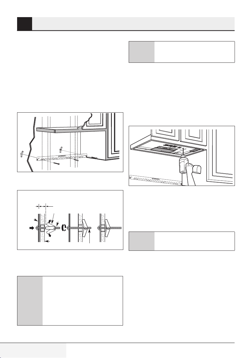
A1. Attach Mounting Plate to Wall
Attach the plate to the wall using toggle bolts. At
least one wood screw must be used to attach the
plate to a wall stud.
1. Remove the toggle wings from the bolts.
2. Insert the bolts into the mounting plate through
the holes designated to go into drywall and
reattach the toggle wings to 3⁄4” (19 mm) onto
each bolt.
To use toggle bolts:
Spacing for Toggles
More Than Wall
Thickness
Mounting
Plate
Toggle Wings
Toggle
Bolt
Be careful to avoid pinching fingers
A
4. Tighten all bolts. Pull the plate away from the
wall to help tighten the bolts.
A2. Use top cabinet template For
preparation of top Cabinet
You need to drill holes for the top support screws,
a hole large enough for the power cord to fit
through, and a cutout large enough for the exhaust adaptor.
• Read the instructions on the TOP CABINET
TEMPLATE.
• Tape it underneath the top cabinet.
• Drill the holes, following the instructions on the
TOP CABINET TEMPLATE.
between the back of the mounting
plate and the wall.
Wall
3. Place the mounting plate against the wall and
insert the toggle wings into the holes in the wall
to mount the plate.
Before tightening toggle bolts and
wood screw, make sure the tabs on
the mounting plate touch the bottom of the cabinet when pushed
C
flush against the wall and that the
plate is properly centered under the
cabinet.
18 / 63 EN
Bolt End
Over The Range Convection Microwave Oven / Installation Manual
A
Wear safety goggles when drilling
holes in the cabinet bottom.
Page 19
Installation
5
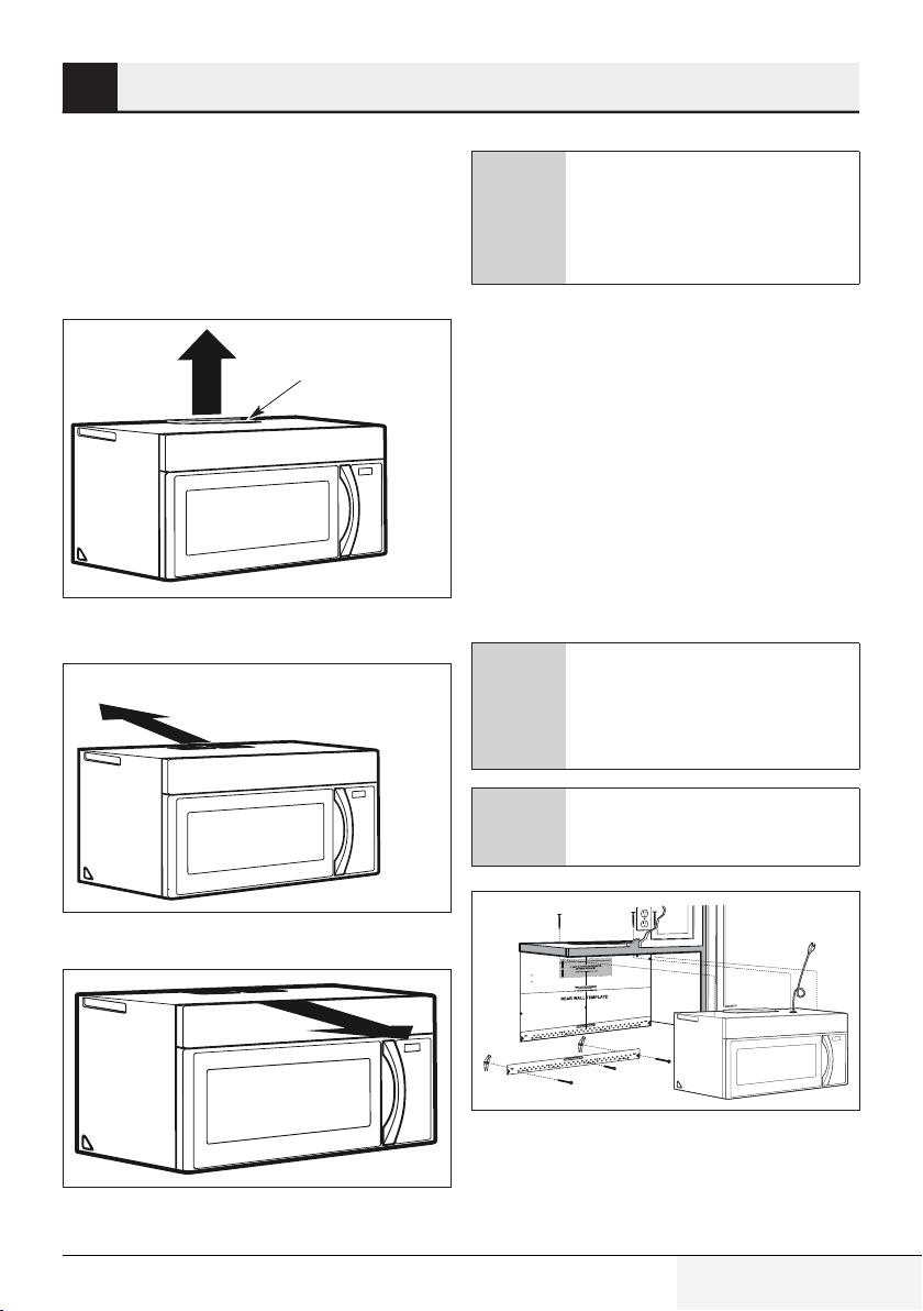
A3. Adapting microwave blower for
outside top exhaust
1. Place the microwave in its upright position, with
the top of the unit facing up. Remove the screw
that holds the blower plate to the microwave.
Remove and save the screw holding the blower
motor to the microwave.
Blower Plate
Back of
Microwave
Blower Motor
Screw
2. Carefully pull out the blower unit. The wires will
extend far enough to allow you to adjust the
blower unit.
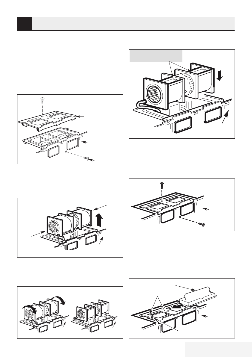
End B
4. Place the blower unit back into the opening.
AFTER: Fan Blade
Openings Facing Top
Back of
Microwave
5. Secure blower unit to microwave with the screw
removed in Step 1. Make sure the screw is tight.
6. Replace blower plate with the screw removed in
Step 1. Make sure the screw is tight.
Back of
Microwave
End A
Back of
Microwave
7. Attach the exhaust adaptor to the top of the
blower plate by sliding it into the guides of
the blower plate. Push in securely until it is in
the locking tabs. Take care to assure that the
3. Roll the blower unit 90° so that fan blade
openings are facing out the top of the
microwave.
Before Rotation After Rotation
Back of
Microwave
Back of
Microwave
damper hinge is installed so that the damper
swings freely.
Adaptor
Guide
Over The Range Convection Microwave Oven / Installation Manual
Back of
Microwave
Locking Tab
19 / 63 EN
Page 20
Installation
5
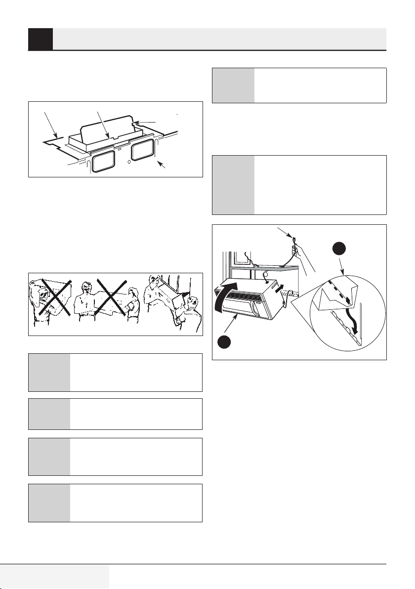
A4. Check for proper damper operation
Blower Plate
• Make sure tape securing damper is removed
and damper pivots easily before mounting
microwave.
• You will need to make adjustments to assure
proper alignment with your house exhaust duct
after the microwave is installed.
A5. Mount the microwave oven
Exhaust Adaptor
Damper
Microwave
Back of
If filler blocks are not used, case
A
1. Lift microwave, tilt it forward, and hook slots
at back bottom edge onto four lower tabs of
mounting plate.
2. Rotate front of oven up against cabinet bottom.
C
2
damage may occur from overtightening screws.
When mounting the microwave
oven, thread power cord through
hole in bottom of top cabinet. Keep
it tight throughout Steps 1–3. Do not
pinch cord or lift oven by pulling cord.
1
For easier installation and personal safety, we recommend that two
C
A
C
C
20 / 63 EN
people install this microwave oven.
Do not grip or use handle during installation.
If your cabinet is metal, use the nylon grommet around the power cord
hole to prevent cutting of the cord.
We recommend using filler blocks if
the cabinet front hangs below the
cabinet bottom shelf.
3. Insert a self-aligning screw through top center
cabinet hole. Temporarily secure the oven by
turning the screw at least two full turns after
the threads have engaged. (It will be completely
tightened later.) Be sure to keep power cord
tight. Be careful not to pinch the cord, especially
when mounting flush to bottom of cabinet.
Over The Range Convection Microwave Oven / Installation Manual
Page 21

Installation
5
4. Attach the microwave oven to the top cabinet.
Cabinet Front
Cabinet Bottom Shelf
Filler Block
Equivalent
to Depth
of Cabinet
Recess
Self-Aligning Screw
Microwave Oven Top
5. Insert 2 self-aligning screws through outer top
cabinet holes. Turn two full turns on each screw.
5
7. Tighten the outer two screws to the top of the
microwave oven. (While tightening screws, hold
the microwave oven in place against the wall
and the top cabinet.)
8. Install grease filters. See the Owner’s Manual
packed with the microwave.
A6. Adjust the exhaust adaptor
Open the top cabinet and adjust the exhaust
adaptor to connect to the house duct.
Blower Plate
Damper
Back of
Microwave
6
6. Tighten center screw completely.
Over The Range Convection Microwave Oven / Installation Manual
For Front-to-Back or
Side-to-Side Adjustment,
Slide the Exhaust Adaptor
as Needed
21 / 63 EN
Page 22

Installation
5
A7. Connecting ductwork
1. Extend the house duct down to connect to the
exhaust adaptor.
2. Seal exhaust duct joints using furnance duct
tape for high temperature applications.
House Duct
22 / 63 EN
Over The Range Convection Microwave Oven / Installation Manual
Page 23

Installation
5
5.2.2 Outside back exhaust
(horizontal duct type B)
E
EDG
TO
"
3/8
12"
MPORTANT TO
VERY I
: IT IS
TE
NO
S
N
IRECTIO
D
HE
WT
LLO
READ AND FO
NS
O
CTI
IN THE INSTALLATION INSTRU
HIS
T
WITH
OCEEDING
RE PR
O
BEF
.
E
T
PLA
REAR WALL TEM
m
tto
o
b
e
n th
4"
sitio
to po
s
ve
r
e
s
te
mpla
e
ll T
Wa
r
ea
s R
i
Th
aust
tal exh
zon
ri
o
e h
cate th
to lo
nd
a
te
a
nting pl
mou
t.
le
t
ou
ed
ition
is pos
te
empla
at the t
k th
c
e
ch
to
vel
e
e a l
. Us
1
.
y
l
ate
ccur
a
r
ft o
on thele
d
stu
ne
t o
s
a
t le
a
mark
nd
a
ate
c
o
2. L
.
e
n
i
rl
te
n
ce
of the
e
id
t s
righ
od
wo
one
ast
t le
a
se
rtant to u
po
It is im
t
tud to support the weigh
s
n a
i
mly
fir
d
unte
mo
w
scre
ed
c
venlyspa
l, e
a
tion
di
d
o a
tw
k
ave. Mar
ow
r
the mic
of
s.
t
l
bo
toggle
ied
suppl
or the
s f
ation
c
lo
re is
e
h
re t
Whe
ns.
catio
marked lo
e
th
es in
ol
h
ll
3. Dri
oles
r h
o
F
s.
w
e
cr
d s
woo
ole for
a 3/16" h
ill
r
d
a stud,
r
s fo
le
o
h
"
/8
l 5
il
r
d, d
tu
s
ith a
w
e up
o not lin
d
that
.
lts
e bo
ggl
to
E
T
A
L
P
G
N
I
NT
U
MO
HE
L T
L
A
T
S
IN
T
NO
DO
IME.
T
HIS
T T
A
l.
ear wal
the r
om
fr
mplate
ove the te
m
4. Re
r
ou
ok for y
uction bo
r
t
stallationIns
h
twe In
vie
e
5.R
ion.
tuat
i
s
n
tio
installa
la
r
ta
l
consu
a
r
apa
j
laho
ltaa
e
u
ev
l
r
Da
.
l
paño
nEs
ne
ó
i
vers
he
n t
i
th holes
gn wi
to ali
holes
k
ar
e and m
Locat
ate.
l
p
mounting
:
RTANT
IMPO
F
E O
SID
N EITHER
STUD O
E
N
O
ST
E AT LEA
T
A
C
LO
.
E
E CENTERLIN
TH
AL, EVENLY
FOR 2 ADDITION
CATION
MARKTHE LO
PLATE
TING
UN
IN THE MO
LTS
BO
GLE
G
O
D T
ACE
SP
.
AREA
line.
he dotted
t
late along
ear wall temp
Trim the r
e dotted line.
h
t
e along
t
pla
em
l t
wal
rear
he
Trim t
in the
gn with holes
i
to al
es
hol
k
Locate and mar
.et
al
p
g
n
i
t
nu
o
m
:
RTANT
IMPO
F
DE O
THER SI
N EI
STUD O
E
E AT LEAST ON
CAT
LO
LINE.
ER
CENT
E
TH
ENLY
L, EV
A
R 2 ADDITION
O
F
N
CATIO
HE LO
T
MARK
PLATE
TING
UN
THE MO
LTS IN
BO
GLE
G
TO
ACED
SP
.
AREA
Installation overview
B1. Prepare Rear Wall
B2. Remove Blower Plate
B3. Attach Mounting Plate to Wall
B4. Prepare Top Cabinet
B5. Adjust Blower
B6. Mount the Microwave Oven
Make sure the screws for the blower
motor and blower plate are securely
tightened when they are reinstalled.
A
This will help to prevent excessive
vibration.
Make sure the motor wiring has
been properly routed and secured,
A
and that the wires are not pinched.
B1. Preparing the rear wall for outside back exhaust
You need to cut an opening in the rear wall for outside exhaust.
NOTE
: IT IS VE
READ
RY IMPOR
A
ND FOLL
T
IN THE IN
ANT
OW
TO
TH
STA
E
DIR
BEFO
L
ECTIONS
TAL
RE PR
OI
N
SNI
OCEED
REAR
TR
U
CTIO
W
ING
ALL
NS
WITH
TEMP
T
his
THI
Re
LATE
ar
S
Wall
.
m
Tem
ounting
pl
a
te
pla
s
erv
tea
estop
out
nd
let
t
o
.
osit
loc
i
ate
on
t
t
hebottom
hehor
1. Us
e
iz
alevelt
o
nt
alexhaust
o
checkt
accurat
hat
ely.
the
2.
tem
Loc
pla
at
t
e
e
andmarka
isposi
right
t
side of
l
ea
stonestudont
th
e
c
e
nter
line.
he
I
tisim
lef
portant
screw
m
t
o
oun
use
t
e
at
df
of
leas
irmly
them
t
on
inastud
i
crowave.M
ewood
loca
tos
t
upport
i
ar
on
k
sfor
twoa
t
he
t
hesupplied
dditional,
wei
3.
Drill
h
olesint
e
v
t
og
enlyspaced
glebolt
h
e
a st
m
s.
ark
ud,
ed
drill
l
oca
a3/
tions.Wheret
that
1
6"
ho
donot line
lefor
woodscrews.
h
toggle
up
wit
hastud,
b
olts.
F
o
d
r
il
l5
/8
"
DO
holes
NO
ATTHI
TINS
T
S
ALL
T
IM
T
E.
HE
4.
Remo
M
OUNTI
v
e
NG
t
hetem
5.
R
plat
eviewth
e
f
rom
e
I
t
nst
he
installationsit
allation
rearwall.
I
n
s
truc
uat
t
ionboo
io
n.
kf
or
y
Dar
levuelta
ala
ve
r
hojapar
sión
en
acon
E
spañ
sul
ol.
tarla
Lo
cate
and
mar
k hol
mou
es to
nting plate.
a
lig
n with ho
IMP
O
RTA
NT:
LOCATE AT LEA
THE
ST ON
C
ENTERLINE.
E
STU
D
ON
M
A
R
K TH
E LOC
SPACE
AT
ION FOR
D TOGG
2 ADDITI
AREA.
LE BOLTS IN THE MOU
Trim
therea
r wall te
mplate a
l
o
n
g the dotted
line
3
/
8" TO E
DGE
1
2
"
tioned
4"
tor
ght
ereis
r
holes
f
or
P
LATE
our
les
in the
EITHER SIDE
O
F
O
NAL
,
EVEN
LY
NTIN
G
PLA
TE
.
Tri
m
the
r
ea
r
wall
template a
l
ong
the
d
otted
line
.
Lo
cate
and
mar
k hol
mountingplate.
es to
alig
n w
ith holes
IMPORTA
in the
NT:
LO
CATE
AT LEAST ON
THE CE
E STU
N
TER
D O
LINE.
MARK TH
N EIT
H
ER SIDE
E
L
OCAT
SP
O
AC
ION FOR
F
E
D
TOGG
2 AD
AREA.
LE BOLTS
DIT
I
O
NAL
IN THE
, EVEN
MOU
LY
NTI
NG PLATE
• Read the instructions on the REAR WALL
TEMPLATE.
• Tape it to the rear wall, lining up with the holes
previously drilled for holes A and B in the wall
plate.
• Cut the opening, following the instructions of
the REAR WALL TEMPLATE.
Over The Range Convection Microwave Oven / Installation Manual
23 / 63 EN
Page 24

Installation
5
B2. Remove blower plate
Remove and save the screw that holds the blower
plate to the microwave. Lift off the blower plate.
Blower Plate
Back of
Microwave
B3. Attach the mounting plate to the
wall
Attach the plate to the wall using toggle bolts. At
least one wood screw must be used to attach the
plate to a wall stud.
1. Remove the toggle wings from the bolts.
2. Insert the bolts into the mounting plate through
the holes designated to go into drywall and
reattach the toggle wings to 3⁄4” (19 mm) onto
each bolt.
To use toggle bolts
Spacing for Toggles More
Than Wall Thickness
Mounting
Plate
Toggle Wings
Toggle
Bolt
3. Place the mounting plate against the wall and
insert the toggle wings into the holes in the wall
to mount the plate.
Before tightening toggle bolts and
wood screw, make sure the tabs on
the mounting plate touch the bottom of the cabinet when pushed
C
A
4. Tighten all bolts. Pull the plate away from the
wall to help tighten the bolts.
B4. Use top cabinet template for
preparation of top cabinet
You need to drill holes for the top support screws
and a hole large enough for the power cord to fit
through.
• Read the instructions on the TOP CABINET
TEMPLATE.
• Tape it underneath the top cabinet.
• Drill the holes, following the instructions on the
TOP CABINET TEMPLATE.
flush against the wall and that the
plate is properly centered under the
cabinet.
Be careful to avoid pinching fingers
between the back of the mounting
plate and the wall.
24 / 63 EN
Wall
Wear safety goggles when drilling
Bolt End
A
holes in the cabinet bottom.
Over The Range Convection Microwave Oven / Installation Manual
Page 25

Installation
Microwave
5
B5. Adapting microwave blower for
outside back exhaust
1. Remove and save screw that holds blower
motor to microwave.
Blower Motor
Back of
Microwave
Blower Motor
Screw
2. Carefully pull out the blower unit. The wires will
extend far enough to allow you to adjust the
blower unit.
Before: Fan Blade
Openings Facing
Forward
End A
End B
3. Roll the blower unit 90°
4. Rotate blower unit counterclockwise 180°.
Before Rotation After Rotation
Back of
Microwave
Back of
Microwave
5. Gently remove the wires from the grooves.
Reroute the wires through grooves on other
side of the blower unit.
Before Rerouting After Rerouting
Wires Routed Through Right Side
Wires Routed Through Left Side
6. Roll the blower unit 90° so that fan blade
openings are facing out the back of the
microwave.
Before Rolling After Rolling
Before Rotation After Rotation
Back of
Microwave
Back of
Microwave
Back of
Microwave
7. Remove the knockout plates in the back of the
unit with snips.
Back of mircrowave
Over The Range Convection Microwave Oven / Installation Manual
Back of
Knockout Plates:
Snip all 4 webs on
each knockout panel
and remove the metal
knockouts for rear airow.
Please take care to
remove any sharp edges
created from removing
the knockout plates.
25 / 63 EN
Page 26

Installation
5
8. Place the blower unit back into the opening.
AFTER: Fan Blade
Openings Facing Back
End A
End B
Do not pull or stretch the blower unit
wiring. Make sure the wires are not
A
C
9. Secure the blower unit to the microwave with
the original screw.
pinched, and that they are properly
secured.
The blower unit exhaust openings
should match exhaust openings on
rear of microwave oven.
Blower Plate
Back of
Microwave
Blower Motor
Screw
11. Attach the exhaust adaptor to the rear of
the oven by sliding it into the guides at the
top center of the back of the oven. Push in
securely until it is in the lower locking tabs.
Take care to assure that the damper hinge is
installed so that it is at the top and that the
damper swings freely.
Adaptor
Back of
Microwave
Guide
Guide
B6. Mount the microwave oven
For easier installation and personal safety, we recommend that two
C
people install this microwave oven.
Locking Tabs
10. Replace the blower plate in the same position
as before with the screw. Make sure the screw
is tight
26 / 63 EN
Over The Range Convection Microwave Oven / Installation Manual
A
C
C
Do not grip or use handle during installation.
If your cabinet is metal, use the nylon grommet around the power cord
hole to prevent cutting of the cord.
We recommend using filler blocks if
the cabinet front hangs below the
cabinet bottom shelf.
Page 27

Installation
Cabinet Front
Cabinet Bottom Shelf
Filler Block
Microwave Oven Top
Equivalent
to Depth
of Cabinet
Recess
Self-Aligning Screw
5
6
5
If filler blocks are not used, case
A
1. Lift microwave, tilt it forward, and hook slots
at back bottom edge onto four lower tabs of
mounting plate.
C
2
2. Rotate front of oven up against cabinet bottom.
3. Insert a self-aligning screw through top center
cabinet hole. Temporarily secure the oven by
turning the screw at least two full turns after
the threads have engaged. (It will be completely
tightened later.) Be sure to keep power cord
tight. Be careful not to pinch the cord, especially
when mounting flush to bottom of cabinet.
damage may occur from overtightening screws.
When mounting the microwave
oven, thread power cord through
hole in bottom of top cabinet. Keep
it tight throughout Steps 1–3. Do not
pinch cord or lift oven by pulling cord.
1
4. Attach the microwave oven to the top cabinet.
5. Insert 2 self-aligning screws through outer top
cabinet holes. Turn two full turns on each screw.
6. Tighten center screw completely.
Over The Range Convection Microwave Oven / Installation Manual
27 / 63 EN
Page 28

Installation
5
7. Tighten the outer two screws to the top of the
microwave oven. (While tightening screws, hold
the microwave oven in place against the wall
and the top cabinet.)
8. Install grease filters. See the Owner’s Manual
packed with the microwave.
5.2.3 Recirculating (non-vented
ductless type C)
E
EDG
O
"T
/8
3
"
2
1
O
TANT T
OR
MP
I
Y
ITIS VER
:
NOTE
NS
O
HE DIRECTI
OWT
LL
O
READ AND F
NS
CTIO
U
NSTR
I
ION
AT
ALL
INST
HE
N T
I
IS
H
H T
IT
W
NG
EEDI
E PROC
R
O
F
BE
.
E
AT
PL
ALL TEM
EAR W
R
m
to
t
bo
e
nth
4"
itio
s
opo
t
s
rve
se
te
la
mp
e
T
ll
Wa
ar
e
R
is
Th
ust
a
h
x
e
al
nt
o
iz
or
h
e
h
et
at
loc
o
t
d
n
a
e
t
a
l
g p
n
ti
n
u
mo
.
t
utle
o
ed
n
o
ositi
p
s
e i
t
la
p
m
te
e
th
at
h
t
ck
he
c
to
el
v
e
l
a
Use
.
1
.
y
l
e
t
ra
u
cc
a
r
o
t
f
e
l
e
th
n
o
d
u
t
s
t one
s
a
e
l
t
a
mark
d
e an
t
ca
Lo
.
2
.
e
n
rli
nte
e
c
e
fth
o
e
d
si
ht
ig
r
d
o
wo
e
n
asto
e
t l
a
e
us
to
nt
rta
o
imp
is
t
I
ht
g
i
we
e
h
t
rt
o
p
p
su
o
dt
stu
a
rmly in
d fi
te
n
u
mo
w
scre
d
e
c
pa
lys
n
l,eve
a
n
io
t
addi
wo
t
rk
Ma
.
ave
microw
e
h
f t
o
ts.
l
le bo
g
og
t
d
lie
p
p
u
s
e
r th
fo
s
n
atio
c
lo
s
i
e
r
e
h
t
s.Where
n
io
d locat
e
k
r
ma
e
inth
s
le
o
h
ll
Dri
3.
les
ho
r
Fo
.
ws
e
scr
od
r wo
o
f
e
ol
h
"
6
/1
3
a
ill
dr
,
ud
t
s
a
r
o
f
s
le
o
h
"
/8
5
d, drill
u
ast
h
e upwit
in
l
t
o
n
do
t
a
th
e bolts.
l
g
g
o
t
TE
A
L
GP
TIN
N
OU
M
E
TH
L
L
TA
S
N
TI
O
DO N
.
E
M
TI
HIS
T
T
A
l.
l
wa
r
a
e re
h
t
rom
f
te
a
l
emp
t
e
h
t
e
v
o
m
. Re
4
r
u
yo
r
fo
k
oo
b
on
ucti
r
Inst
lation
l
sta
In
the
view
5. Re
n.
atio
tu
si
tion
lla
a
t
s
n
i
tarla
l
u
ons
c
a
par
ja
ho
la
a
a
t
l
ue
v
le
r
Da
añol.
p
Es
n
e
n
ió
rs
e
v
e
in th
es
h hol
gn wit
i
l
a
es to
hol
mark
d
n
a
e
t
a
Loc
ate.
l
p
ng
i
mount
ANT:
T
MPOR
I
HER SIDEOF
T
I
E
N
O
NESTUD
O
AST
E
L
E AT
T
LOCA
E.
RLIN
TE
N
CE
E
H
T
EVENLY
ADDITIONAL,
R2
O
N F
IO
T
CA
HELO
MARK T
TE
A
PL
ING
T
N
MOU
E
TH
SIN
LT
O
B
TOGGLE
D
SPACE
.
REA
A
ne.
li
ed
t
dot
e
h
t
g
on
plate al
em
ll t
a
w
r
e rea
im th
r
T
ine.
ottedl
d
he
t
g
n
o
late al
p
tem
all
w
r
e rea
th
m
Tri
e
h
t
in
s
e
l
o
h
h
t
gnwi
i
l
a
o
t
mark holes
and
e
t
ca
o
L
.
e
lat
p
g
untin
o
m
:
NT
RTA
MPO
I
F
O
ER SIDE
H
T
I
ON E
D
U
T
NES
O
ST
LEA
E AT
AT
C
LO
E.
ERLIN
ENT
EC
TH
EVENLY
,
AL
2 ADDITION
R
O
TION F
LOCA
E
MARK TH
E
PLAT
G
N
I
UNT
MO
E
H
T
SIN
T
L
BO
LE
G
G
CED TO
A
SP
A.
RE
A
Installation overview
C1. Attach Mounting Plate to Wall
C2. Prepare Top Cabinet
C3. Check Blower Plate
C4. Mount the Microwave Oven
C5. Install or change Charcoal Filter
28 / 63 EN
Over The Range Convection Microwave Oven / Installation Manual
A
Make sure the screws for the blower
motor and blower plate are securely
tightened when they are reinstalled.
This will help to prevent excessive
vibration.
Page 29

Installation
5
Make sure the motor wiring has
A
C1. Attach the mounting plate to the
wall
Attach the plate to the wall using toggle bolts. At
least one wood screw must be used to attach the
plate to a wall stud.
1. Remove the toggle wings from the bolts.
2. Insert the bolts into the mounting plate through
the holes designated to go into drywall and
reattach the toggle wings to 3⁄4” (19 mm) onto
each bolt.
To use toggle bolts
been properly routed and secured,
and that the wires are not pinched.
Before tightening toggle bolts and
wood screw, make sure the tabs on
the mounting plate touch the bottom of the cabinet when pushed
C
A
4. Tighten all bolts. Pull the plate away from the
wall to help tighten the bolts.
C2. Use top cabinet template for
preparation of top cabinet
You need to drill holes for the top support screws
and a hole large enough for the power cord to fit
through.
flush against the wall and that the
plate is properly centered under the
cabinet.
Be careful to avoid pinching fingers
between the back of the mounting
plate and the wall.
Spacing for Toggles
More Than Wall
Thickness
Mounting
Plate
3. Place the mounting plate against the wall and
insert the toggle wings into the holes in the wall
to mount the plate.
Over The Range Convection Microwave Oven / Installation Manual
Toggle Wings
Toggle
Bolt
Wall
Bolt End
• Read the instructions on the TOP CABINET
TEMPLATE.
• Tape it underneath the top cabinet.
• Drill the holes, following the instructions on the
TOP CABINET TEMPLATE.
Wear safety goggles when drilling
A
holes in the cabinet bottom.
29 / 63 EN
Page 30

Installation
Blower Plate
Cabinet Front
Cabinet Bottom Shelf
Filler Block
Microwave Oven Top
Equivalent
to Depth
of Cabinet
Recess
Self-Aligning Screw
5
C3. Check blower plate
• Place the microwave in its upright position, with
the top of the unit facing up.
• Check to see that the blower plate is correctly
installed on the unit.
C4. Mount the microwave oven
For easier installation and personal safety, we recommend that two
C
A
people install this microwave oven.
Do not grip or use handle during installation.
1. Lift microwave, tilt it forward, and hook slots
at back bottom edge onto four lower tabs of
mounting plate.
When mounting the microwave
oven, thread power cord through
hole in bottom of top cabinet. Keep
C
2
2. Rotate front of oven up against cabinet bottom.
3. Insert a self-aligning screw through top center
cabinet hole. Temporarily secure the oven by
turning the screw at least two full turns after
the threads have engaged. (It will be completely
tightened later.) Be sure to keep power cord
tight. Be careful not to pinch the cord, especially
when mounting flush to bottom of cabinet.
4. Attach the microwave oven to the top cabinet.
it tight throughout Steps 1–3. Do not
pinch cord or lift oven by pulling cord.
1
C
C
A
30 / 63 EN
If your cabinet is metal, use the nylon grommet around the power cord
hole to prevent cutting of the cord.
We recommend using filler blocks if
the cabinet front hangs below the
cabinet bottom shelf.
If filler blocks are not used, case
damage may occur from overtightening screws.
Over The Range Convection Microwave Oven / Installation Manual
Page 31

Installation
5
6
Charcoal
Filter
5
5. Insert 2 self-aligning screws through outer top
cabinet holes. Turn two full turns on each screw.
6. Tighten center screw completely.
7. Tighten the outer two screws to the top of the
microwave oven. (While tightening screws, hold
the microwave oven in place against the wall
and the top cabinet.)
1. Remove screws on top of grille using a #1
Phillips screwdriver.
2. Open the door.
3. Remove the grille. Pull the grille straight off.
4. Install the charcoal filter: Insert filter upper in
the unit and then pull down filter. When properly
installed, the wire mesh of the filter should be
visible from the front.
Insert mesh-side up
8. Install grease filters. See the Owner’s Manual
packed with the microwave.
C5. Installing or change the charcoal
filter
The charcoal filter is factory installed
in recirculating models. Follow these
steps to replace a filter or to install a
C
Over The Range Convection Microwave Oven / Installation Manual
filter after converting a vented model to recirculating operation.
31 / 63 EN
Page 32

How to use the product
6
Before you use your over the range
C
1. Make sure the product has been installed
according to instructions.
2. Remove all packing material from the product.
3. Install turntable ring and glass tray in cavity
4. Replace house fuse or turn breaker back on.
5. Plug power cord into a dedicated 15 amp to 20
amp electrical outlet.
6. Read the user manual.
7. Keep installation instructions for the local
inspectors’s use.
product;
32 / 63 EN
Over The Range Convection Microwave Oven / Installation Manual
Page 33

Avant d'utiliser l'appareil, veuillez lire ce manuel !
Chère cliente, cher client,
Merci d’avoir choisi les produits Blomberg. Nous espérons que ce produit, fabriqué dans
des installations modernes et soumis à un processus de contrôle qualité rigoureux,
vous offre les meilleures performances possibles. C’est pourquoi nous vous recommandons, avant d’utiliser ce produit, de lire attentivement ce manuel et tous les autres
documents fournis et de les conserver soigneusement pour toute consultation future.
Si vous confiez le produit à quelqu’un d’autre, n’oubliez pas de lui remettre également
le manuel d’utilisation. Veillez à bien respecter les consignes et les instructions figurant
dans le manuel d’utilisation.
Signification des symboles
Les symboles suivants sont utilisés tout au long de ce manuel :
Informations importantes et conseils
C
A
B
utiles sur l’utilisation de l’appareil.
Avertissement sur les situations dangereuses concernant la sécurité des
biens et des personnes.
Avertissement contre le risque
d’électrocution
Avertissement en cas de contact avec
une surface brûlante.
Ce produit a été fabriqué dans une usine moderne respectueuse de l’environnement.
Page 34

TABLE DES MATIÈRES
1 Consignes importantes 35
1.1 Consignes générales de sécurité ....................35
1.1.1 Sécurité électrique ............................................36
2 Votre four à micro-ondes à
convection à hotte intégrée 37
2.1 Vue d'ensemble ...................................................... 37
2.2 Données techniques ...........................................37
3 Dégagements pour
l’installation 38
4 Conduite d'évacuation externe 39
4.1 Installation de la hotte de ventilation ..........39
4.1.1 Évacuation à l’extérieur par le dessus
(exemple uniquement) ..............................................39
4.1.2 Évacuation à l’extérieur par l’arrière
(exemple uniquement) ............................................. 40
4.1.3 Raccordement de l’évacuation au
conduit .............................................................................. 41
4.1.4 Longueur maximale des conduits ..............41
4.1.5 Coudes, adaptateurs de transition, évents
de toit et muraux, etc. ................................................41
4.2 Dommages –expédition/installation ............42
4.3 Pièces comprises ..................................................42
4.3.1 Sachet de quincaillerie ....................................42
4.3.2 Pièces supplémentaires .................................43
4.4 Outils et matériaux nécessaires ....................44
5 Installation 45
5.1 Mise en place de la plaque de montage .......45
5.1.1 Enlèvement du four à micro-ondes de la
boîte/enlèvement de la plaque de montage ....45
5.1.2 Localisation des montants ............................45
5.1.3 Établissement de l’emplacement de la
plaque murale sous votre armoire ....................... 46
5.1.4 Alignement de la plaque murale .................47
5.2 Types d’installation (choisissez A, B ou C) . 48
5.2.1 Évacuation à l’extérieur par le dessus
(Type A - conduit vertical)........................................48
5.2.2 Évacuation à l’extérieur par l’arrière
(conduit horizontal de type B) ................................54
5.2.3 Recyclage d’air (évacuation sans
conduit de type C) ........................................................59
6 Utilisation du produit 63
34 / 63 FR
Four à micro-ondes à convection à hotte intégrée / Manuel d’installation
Page 35

1 Consignes importantes
1.1 Consignes générales
de sécurité
Lisez et conservez ces
C
Cela :
•facilitera l’installation,
•vous aidera à l’avenir si vous avez
des questions et
•vous aidera en cas d’inspection du
système électrique.
Si vous avez des questions ou besoin de réparations, appelez votre
vendeur. Lors de l’appel, ayez soin
d’indiquer les numéros de modèle et
de série du four à micro-ondes.
A
Veuillez lire toutes les instructions
avant d'utiliser l'appareil.
Ce produit nécessite une prise de
courant à trois broches mise à la
terre.
instructions
AVERTISSEMENT :
Pour réduire les risques
d’incendie, de choc électrique ou de blessures, il
est important de toujours
observer quelques mesures de sécurité de élémentaires, y compris les
suivantes :
Avant d’entreprendre l’installation,
l’installateur doit vérifier la continuité à la boîte à prises pour s’assurer qu’elle est adéquatement mise à
la terre.
Si ce n’est pas le cas, ou si la boîte à
prises ne répond pas aux exigences
électriques indiquées (à la section
EXIGENCES ÉLECTRIQUES), faites
appel à un électricien qualifié pour
corriger tout défaut.
Pour votre sécurité, retirez le fusible ou déclenchez le disjoncteur
avant d’entreprendre l’installation,
afin d’éviter toute blessure grave ou
mortelle.
Pour votre sécurité, la surface de
montage doit être en mesure de
supporter la charge des armoires,
ainsi qu’un poids supplémentaire
de 28,5 à 38,5 kg (63 à 85 livres)
correspondant au poids du produit,
et la charge du four qui peut atteindre 22,7 kg (50 livres), pour un
poids total de 51,3 à 61,2 kg (113 à
135 livres).
Pour votre sécurité, évitez d’installer ce produit sous des armoires
aménagées en îlot ou en péninsule.
Fixez-le À LA FOIS à une armoire supérieure ET à un mur.
Four à micro-ondes à convection à hotte intégrée / Manuel d’installation
35 / 63 FR
Page 36

1 Consignes importantes
Pour faciliter l’installation et pour
votre sécurité, il est recommandé
que l’installation de ce produit soit
effectuée par deux personnes.
Pour votre sécurité, mettez convenablement cet appareil à la terre
pour éviter un choc grave ou mortel.
Pour diminuer les risques de choc
électrique, le cordon d’alimentation de cet appareil est muni d’une
fiche à trois broches (mise à la terre)
qui correspond à une prise murale
Branchez la fiche du cordon d’alimentation sur une prise avec mise
à la terre de 15 à 20 ampères sur
un circuit de dérivation séparé. La
boîte à prises doit se trouver dans
l’armoire située au-dessus du four
à micro-ondes. La boîte à prises et
le circuit d’alimentation doivent être
installés par un électricien qualifié et respecter le Code national
de l’électricité ou le code local en
vigueur.
à trois broches (prise dotée d’une
mise à la terre).
Ne coupez, ne déformez et ne retirez en aucun cas aucune broche de
la fiche du cordon d’alimentation.
N’utilisez pas de rallonge électrique.
1.1.1 Sécurité électrique
Les caractéristiques nominales du
produit sont : 120 volts CA, 60 hertz,
15 ampères et 1 500 watts.
Branchez ce produit à un circuit
d’alimentation de tension et de fréquence appropriées.
La taille des câbles doit être
conforme aux exigences du Code
national d’électricité ou du code local en vigueur pour cette puissance
nominale.
36 / 63 FR
Four à micro-ondes à convection à hotte intégrée / Manuel d’installation
Page 37

Votre four à micro-ondes à convection à hotte intégrée
2
2.1 Vue d'ensemble
C
2.2 Données techniques
A
B
Dimensions du produit
A-Hauteur 15,7 ˝ (39,9 cm)
B-Largeur 29,9 ˝ (75,9 cm)
C-Profondeur 15,0 ˝ (38,1 cm)
Dimensions de découpe
Hauteur (Min.) 16,75 ˝ (42,5 cm)
Hauteur (Max.) 17,0 ˝ (43,2 cm)
Largeur (Min.) 30,0 ˝ (76,2 cm)
Profondeur (Min.) 12,0 ˝ (30,5 cm)
Profondeur (Max.) 13,0 ˝ (33,0 cm)
Four à micro-ondes à convection à hotte intégrée / Manuel d’installation
37 / 63 FR
Page 38

Dégagements pour l’installation
3
Le rebord inférieur
de l'armoire doit
être à au moins
30 pouces
Dosseret
(76,2 cm) de la
surface de cuisson.
Au moins 66
pouces
(167,6 cm)
entre le sol et le
dessus du four à
micro-ondes.
[12“ (30.5 cm) min.]
3
16
⁄4 “ (42.5 cm)
30
“ (76.2 cm)
“ (5.1 cm)
2
“
30
(76.2 cm)
min.
Il faut un espace d’au moins 30 po
(76,2 cm) entre les armoires, sans
C
obstructions
Si l’évacuation de l’air de votre
four à micro-ondes s’effectue vers
l’extérieur, consultez la section
C
« Évacuation de la hotte pour la préparation du conduit d’évacuation ».
Lorsque vous installez le four à micro-ondes sous des armoires dont le
fond est lisse et plat, suivez attentivement les instructions du gabarit
C
pour armoire supérieure concernant
le dégagement du cordon d’alimentation.
38 / 63 FR
Four à micro-ondes à convection à hotte intégrée / Manuel d’installation
Page 39

Conduite d'évacuation externe
4
4.1 Installation de la hotte de
ventilation
Lisez ces instructions si vous décidez d’évacuer l’air du ventilateur à
l’extérieur. Si vous décidez de recy-
C
4.1.1 Évacuation à l’extérieur par
le dessus (exemple uniquement)
Le tableau suivant décrit une façon possible d’installer les conduits.
cler l’air dans la pièce, rendez-vous
au chapitre 5.
C
Pièces des conduits Longueur
Évent de toiture 24 pi (7,3 m) x (1) = 24 pi (7,3 m)
12 pi (3,6 m)
Conduit droit
(rond de
6 po/15,2 cm)
Adaptateur de
transition
rectangulaire à
rond*
Les longueurs équivalentes des pièces des conduits sont
fondées sur des tests réels et reflètent les exigences à
suivre pour une bonne ventilation avec n’importe quelle
hotte.
Si vous utilisez un adaptateur de
transition rectangulaire à rond, les
coins inférieurs du registre devront
être coupés aux dimensions de
l’adaptateur au moyen des cisailles
de ferblantier afin que le registre
puisse se déplacer librement.
équivalente
12 pi (3,6 m) x (1) = 12 pi (3,6 m)
5 pi (1,5 m) x (1) = 5 pi (1,5 m)
Nombre
x
utilisé
Longueur
totale
Longueur
=
équivalente
= 41 pi (12,5 m)
Four à micro-ondes à convection à hotte intégrée / Manuel d’installation
39 / 63 FR
Page 40

Conduite d'évacuation externe
4
4.1.2 Évacuation à l’extérieur par
l’arrière (exemple uniquement)
Le tableau suivant décrit une façon possible d’installer les conduits.
C
C
Pièces des conduits Longueur
Évent mural 40 pi (12,2 m) x (1) = 40 pi (12,2 m)
3 pi Conduit droit
(rectangulaire de
3¼ po x 10 po/8.2
x 25,4 cm)
Coude de 90 degrés
Les longueurs équivalentes des pièces des conduits sont fondées sur des tests réels et reflètent les exigences à suivre pour
une bonne ventilation avec n’importe quelle hotte.
Dans le cas d’une évacuation par
l’arrière, assurez-vous d’aligner le
conduit d’évacuation avec les espaces entre les poteaux muraux ; il
est également possible de préparer le mur lors de sa construction
en laissant suffisamment d’espace
entre les poteaux muraux pour recevoir le conduit.
Si vous devez installer des conduits,
veuillez noter que la longueur totale des conduits rectangulaires de
31⁄4 po x 10 po (8.2 x 25.4 cm) ou
ronds de 6 po (15,2 cm) de diamètre
ne doit pas dépasser une longueur
équivalente de 120 pieds (36,5 m).
équivalente
3 pi (0,9 m) x (1) = 3 pi (0,9 m)
10 pi (3 m) x (2) = 20 pi (3 m)
C
Nombre
x
utilisé
Longueur
totale
L’évacuation à l’extérieur nécessite
un CONDUIT D’ÉVACUATION POUR
HOTTE. Lisez attentivement les remarques suivantes. Il est important
que l’évacuation soit installée en
empruntant le chemin le plus direct
et en utilisant le moins de coudes
possible. Cela permet une évacuation directe de l’air et contribue à
éviter les blocages. Assurez-vous
également que les registres pivotent librement et que rien n’obstrue
les conduits.
Longueur
=
équivalente
= 63 pi (19,2 m)
40 / 63 FR
Four à micro-ondes à convection à hotte intégrée / Manuel d’installation
Page 41

Conduite d'évacuation externe
4
4.1.3 Raccordement de
l’évacuation au conduit
L’évacuation pour hotte a été conçue pour être
raccordée à un conduit rectangulaire standard
de 31⁄4 po x 10 (8,2 x 25,4 cm). Si un conduit rond
est nécessaire, utilisez un adaptateur de transition rectangulaire à rond. N’utilisez pas de conduit
ayant un diamètre inférieur à 6 po (15,2 cm).
4.1.5 Coudes, adaptateurs de
transition, évents de toit et
muraux, etc.
Ces éléments offrent une résistance accrue à la
circulation de l’air et sont équivalents à une section de conduit droit plus longue que leurs dimensions physiques réelles. Lorsque vous calculez
la longueur totale des conduits, additionnez les
longueurs équivalentes de l’ensemble des adapta-
4.1.4 Longueur maximale des
conduits
Pour permettre une circulation satisfaisante de
l’air, la longueur totale des conduits rectangulaires
de 31⁄4 po x 10 po (8.2 x 25.4 cm) ou ronds de 6 po
(15,2 cm) de diamètre ne doit pas dépasser une
teurs de transition plus la longueur de toutes les
sections de conduit droit. Le tableau ci-dessous
vous indique comment calculer la longueur équivalente totale des conduits en utilisant la longueur
équivalente en pieds approximative de certains
conduits types.
longueur équivalente de 120 pieds (36,5 m).
Pièces des conduits Longueur
Adaptateur de transition
rectangulaire à rond*
équivalente
5 pi (1,5 m) x ( ) = Pieds ou m
x
Nombre
utilisé
Longueur
=
équivalente
Évent mural 40 pi (12,2 m) x ( ) = Pieds ou m
Coude de 90 degrés 10 pi (3 m) x ( ) = Pieds ou m
Coude de 45 degrés Coude de
45 degrés
Coude de 90 degrés 25 pi (7,6 m) x ( ) = Pieds ou m
x ( ) = Pieds ou m
Four à micro-ondes à convection à hotte intégrée / Manuel d’installation
41 / 63 FR
Page 42

Conduite d'évacuation externe
4
C
C
Coude de 45 degrés 5 pi (1,5 m)
Évent de toiture 24 pi (7,3 m)
Conduit droit rond de 6 po
(15,2 cm) ou rectangulaire
de
31⁄4 po x 10 po
(8,2 x 25,4 cm)
Si vous utilisez un adaptateur de
transition rectangulaire à rond, les
coins inférieurs du registre devront
être coupés aux dimensions de
l’adaptateur au moyen des cisailles
de ferblantier afin que le registre
puisse se déplacer librement.
Dans le cas d’une évacuation par
l’arrière, assurez-vous d’aligner le
conduit d’évacuation avec les espaces entre les poteaux muraux ; il
est également possible de préparer le mur lors de sa construction
en laissant suffisamment d’espace
entre les poteaux muraux pour recevoir le conduit.
1 pi (0,3 m)
• Si l’appareil est endommagé par l’installateur
(s’il s’agit d’une personne différente du client),
la réparation ou le remplacement doivent
faire l’objet d’une entente entre le client et
l’installateur.
4.3 Pièces comprises
4.3.1 Sachet de quincaillerie
Pièce Quantité
x ( ) = Pieds ou m
x ( ) = Pieds ou m
x ( ) = Pieds ou m
Longueur totale
des conduits
Vis à bois
(1/4 po x 2 po)
Boulons à ailettes
(et écrous à oreilles)
(3/16 x 3 po)
= Pieds ou m
2
2
4.2 Dommages –expédition/
installation
• Si l’appareil est endommagé durant le transport,
retournez-le au magasin où vous l’avez acheté
pour réparation ou remplacement.
• Si l’appareil est endommagé par le client, la
réparation ou le remplacement reste à la charge
du client.
42 / 63 FR
Four à micro-ondes à convection à hotte intégrée / Manuel d’installation
Vis à métaux à
auto-alignement
(1/4 po - 28 x 31/4 po)
Passe-fil en nylon
(pour armoires en
métal)
Vous trouverez les pièces de quincaillerie dans un sachet
fourni avec l’appareil. Vérifiez que vous avez reçu toutes ces
pièces. Vérifiez que vous disposez de toutes ces pièces.
REMARQUE : Des pièces supplémentaires sont incluses.
3
1
Page 43

Conduite d'évacuation externe
4
4.3.2 Pièces supplémentaires
Pièce Quantité
Gabarit pour
armoire supérieure et
Gabarit pour mur
arrière
Instructions
d’installation
1
1
1
Filtres à graisse
emballés séparément
Adaptateur de conduit
d’évacuation
Plateau en verre 1
Anneau de plateau
tournant
Vous trouverez les pièces de quincaillerie dans un sachet
fourni avec l’appareil. Vérifiez que vous avez reçu toutes ces
pièces. Vérifiez que vous disposez de toutes ces pièces.
REMARQUE : Des pièces supplémentaires sont incluses.
2
1
1
Four à micro-ondes à convection à hotte intégrée / Manuel d’installation
43 / 63 FR
Page 44

Conduite d'évacuation externe
4
4.4 Outils et matériaux
nécessaires
Tournevis Phillips no 1
Cisailles de ferblantier
(pour couper le registre,
si nécessaire)
Gants
Ciseaux (pour couper le
gabarit, si nécessaire)
Crayon
Scie (sauteuse, trépan ou à guichet)
Ruler or tape measure and
straight edge
Perceuse électrique avec
forets de 3/16 , 1⁄2 et 5⁄8.
Localisateur de
montant ou
Marteau (facultatif)
Règle ou ruban à
mesurer et règle
droite
Entretoises ou pièces de
bois de récupération, le cas
échéant, pour l’espacement
avec l'armoire supérieure
(utilisées uniquement pour
l’installation sous une armoire
dont le fond est doté d’un
rebord)
Lunettes de sécurité
Niveau
Ruban adhésif en toile et ruban-cache
44 / 63 FR
Four à micro-ondes à convection à hotte intégrée / Manuel d’installation
Page 45

Installation
5
5.1 Mise en place de la plaque
de montage
5.1.1 Enlèvement du four à microondes de la boîte/enlèvement de
la plaque de montage
1. Retirez les directives d’installation, les filtres,
le plateau en verre et le sachet de quincaillerie.
N’enlevez pas la protection en polystyrène à
l’avant du four.
2. Repliez complètement les 4 rabats contre les
côtés de la boîte. Ensuite, retournez le four et
la boîte avec précaution. Le four devrait reposer
sur la styromousse.
Boîte
Styromousse
3. Tirez la boîte vers le haut pour dégager le four.
4. Coupez le centre du sac en plastique pour retirer
la plaque de montage
5. Enlevez les vis de la plaque de montage. Cette
plaque sera utilisée comme gabarit pour le mur
arrière et pour le montage. Remettez en place
les vis retirées préalablement.
5.1.2 Localisation des montants
1. Localisez les montants en utilisant une des
méthodes suivantes :
• Localisateur de montant – dispositif magnétique
permettant de localiser les clous.
• Utilisez un marteau pour frapper légèrement
sur la surface de montage jusqu’à ce que vous
n’entendiez plus un son creux. Cela signifie que
vous avez trouvé un montant.
2. Après avoir localisé le(s) montant(s), trouvez-en
le centre en sondant le mur à l’aide d’un petit clou
afin de trouver les rebords du montant. Puis faites
une marque à mi-chemin entre les deux bords. Le
centre de tout montant adjacent doit se trouver à
16 po (40,6 cm) ou 24 po (61 cm) de cette marque.
3. Tracez une ligne verticale marquant le milieu
des montants.
A
AVERTISSEMENT :
à micro-ondes doit être fixé à au
moins un montant du mur.
Le four
Vis
Plaque de montage
Vis
Four à micro-ondes à convection à hotte intégrée / Manuel d’installation
45 / 63 FR
Page 46

Installation
3/8
"
TO EDGE
NO
TE:
I
TIS VER
YIMPOR
T
AN
T TO
R
EAD A
N
D
FO
L
LO
W
T
H
E D
IR
ECTI
O
N
S
I
N
T
H
E
IN
ST
ALL
ATIO
N
IN
STR
U
CTI
O
NS
BEFO
RE
PR
O
C
EED
IN
G
W
ITH
T
HI
S
R
EAR
W
AL
L T
E
MPL
ATE.
Th
is
R
ea
r
W
a
ll
Te
mp
la
t
e s
er
v
e
s
t
o po
s
it
i
o
n
t
h
e
bott
o
m
mo
untin
g
pla
t
e
a
ndt
o l
o
c
at
e
the h
o
r
iz
o
n
tal e
x
h
aust
ou
tlet
.
1
.
U
s
e
a
lev
el to
check
th
at
th
e
te
mp
lat
e is
positio
n
e
d
ac
c
u
r
at
ely
.
2
.
L
o
c
a
te
a
nd
mar
k
a
t lea
s
t
o
n
e
s
t
ud
o
n
t
he
le
f
t
or
rig
ht
s
id
e
o
f
th
e c
e
n
te
rl
in
e.
It
is
i
mp
o
rt
a
n
t
t
o
u
s
e a
t leas
t
o
n
e
w
oo
d
s
crew mo
unt
ed
f
ir
mly in
a
s
t
u
d
t
o
su
ppo
r
t
t
h
e
w
eight
of
th
e
mic
r
o
w
a
v
e
.
Ma
rk
t
w
o
a
dd
itiona
l,
e
venl
y
s
p
a
ce
d
loc
a
tio
ns fo
r
th
e
supp
lie
d t
og
g
le
b
olts
.
3.Dr
ill
h
oles
in
t
h
e
ma
r
ked
lo
c
atio
n
s
.
Where th
e
re
is
a
stud, drill
a
3/
1
6"ho
lef
o
r
wo
od
s
cr
e
w
s
. Fo
r
h
o
le
s
th
a
t
do n
o
t lin
e u
p
w
ith
a
s
t
u
d,
d
r
ill
5
/
8" h
o
le
s fo
r
tog
g
le
bolts.
DO
N
OT
INSTA
L
L
TH
E
MO
U
NTIN
G
P
L
ATE
AT
THIS TIME
.
4
.
R
em
o
v
e
th
e
te
mp
la
te
fr
om
t
h
e
rear
wall.
5
.R
e
v
ie
w
t
he
In
s
ta
ll
atio
n
Ins
tru
c
t
io
n
bo
o
k fo
r
your
in
stallatio
n
situa
tio
n.
Lo
cate
an
d
ma
rk
hol
es to ali
g
n w
i
t
h
h
ol
e
s
i
n t
h
e
mountin
g
pl
a
t
e
.
IM
PO
R
T
ANT
:
LOC
A
TE ATLEAST
ONE STU
D
ON
EITH
ER
SID
E
OF
THE C
EN
T
ER
LIN
E.
MARK
TH
E
LOCATIO
N
FO
R
2 AD
D
ITIONAL,
EVEN
L
Y
SPAC
ED TOGGLE
BO
L
T
S
I
N
TH
EM
OU
N
T
I
N
G
PLATE
AR
EA
.
Lo
cate
an
d
ma
rk
hol
es t
o al
ig
n wi
t
h
hole
sin the
moun
tin
g pl
a
t
e
.
IMPO
R
T
AN
T:
LOC
AT
E AT
LEAS
T
ON
E ST
U
D
ON EI
T
H
ERSID
E
O
F
TH
E
C
EN
TE
R
LIN
E.
MARK
T
H
E
LO
CATIO
N
FOR
2AD
D
I
TION
AL
, EVEN
L
Y
SPA
C
E
D TO
G
GLE
BO
L
T
S
I
N
TH
E
MOU
N
TIN
AR
EA.
Trim
ther
e
ar
wall
t
em
p
lat
e
al
ong
the
d
otted
l
i
ne.
Trim
the
r
ear
wal
l
tem
pl
atealong
th
e
dotte
d
li
ne.
12
"
4"
D
arle
v
u
el
t
a
a
la
h
o
ja
p
a
rac
o
n
s
ult
a
r
la
v
e
r
si
ó
n
e
n
E
s
p
añ
o
l.
5
5.1.3 Établissement de l’emplacement
de la plaque murale sous votre armoire
Emplacement de la plaque—sous une armoire
à fond plat
N
OT
E:
I
T
IS
V
ER
R
EA
Y
D
I
M
A
P
ND
OR
F
T
O
AN
I
NT
L
LO
T
TO
H
WTH
EI
NST
ED
A
BE
I
L
RE
L
A
FOR
C
T
I
TI
ON
O
E
NS
P
I
N
R
S
OC
T
R
RUCTI
E
E
AR
E
D
I
W
N
ONS
GW
A
LL
ITH
T
E
3/
M
This
8"
TH
P
T
L
OED
Rear
I
A
S
T
G
E
W
E
.
a
l
l
T
moun
e
m
p
l
ti
a
ngpl
t
e
se
a
rve
t
e
12"
s
a
o
n
u
t
o
d
t
le
p
to
t.
o
s
l
o
itio
c
a
n
te
th
t
he
eb
1
. Use
h
o
o
t
t
rizo
o
m
a
n
t
le
a
l
v
ex
elto
h
a
u
c
s
he
a
t
c
c
c
k
u
r
th
a
t
a
e
tth
l
y
.
e
t
2
e
.
mp
L
o
la
ca
t
e
t
e
i
sp
and
o
s
ma
i
ti
o
r
ne
k
r
i
g
a
d
h
t
t
le
si
a
deo
ston
fth
e
s
e
tu
cen
d
4"
onth
te
r
l
i
n
e
e
I
t
lef
.
i
s
to
imp
r
o
s
r
crew
t
a
n
t
tou
m
o
un
s
e
t
a
e
df
t
le
o
i
f
rmly
a
th
st
em
o
in
n
ew
icr
a
st
o
o
w
u
od
ave. M
d
to
lo
c
su
a
t
a
p
io
r
p
ns f
k
ort
t
wo
or
t
h
e
a
t
h
d
w
e
di
e
3
s
ti
ig
.D
up
on
h
rill
t
p
al
l
i
, e
h
ed
o
v
l
t
e
e
o
n
s
g
l
g
y
in
le
s
th
p
bo
a
em
a
ce
lt
stu
s
d
a
.
r
k
d, dril
e
d
loc
l
a
a
ti
3
o
/16
n
t
h
s
a
"
.W
t
h
d
o
h
o
l
e
er
n
f
ot
e
o
th
r
l
w
i
n
e
oo
eu
r
eis
d
t
o
p
s
gg
w
cr
l
it
e
e
h
w
b
astu
s. F
o
lts
.
o
d
r
,
h
d
o
r
le
il
l 5
s
/8
"
h
o
DO
l
e
s
NOT I
fo
r
AT
N
T
ST
HIST
A
L
L
I
T
ME.
H
E
4
MOU
.
R
e
mo
N
T
v
I
N
e
th
G
P
e
L
te
5
A
.
m
T
R
p
E
e
l
a
v
t
ie
efr
w
t
o
h
m the
e
In
s
t
r
a
in
e
l
l
a
s
a
r
t
t
a
io
w
ll
nI
a
a
ll
ti
.
n
o
s
n
t
ru
s
i
t
cti
u
a
o
t
nb
i
on
o
.
o
k
f
o
r
y
ou
r
D
a
r
l
ev
ue
lta
a
la
v
e
h
rs
o
ió
jap
n
e
a
n
r
a
E
c
s
on
p
añol
s
ult
.
arla
Loc
a
te
and m
ar
k
m
h
olesto
o
un
t
i
ngpl
a
li
gn
ate.
w
ith
I
M
ho
PORTA
les
int
he
NT
:
LOC
ATE
A
T
LE
A
ST
T
H
EC
O
N
E
ENT
ST
ER
UDO
LI
N
N
M
E
AR
.
E
IT
K
H
T
ER
H
E
S
L
I
DE
OC
A
OF
SP
T
I
O
A
CED
N
FO
T
R2A
OG
G
D
L
D
A
EB
R
IT
E
IO
O
A.
LTSI
N
A
L
,
N TH
EV
E
N
E
LY
MOUNT
IN
G
P
L
A
T
E
Tr
i
mth
er
ear
w
al
l
te
mpla
t
e
al
o
ngt
h
e
d
o
t
t
ed
li
n
e.
Àt least 30
Tracez une ligne verticale sur le mur au centre de
l'espace de 30 po de large. Collez le gabarit pour
mur arrière sur le mur le long de la ligne centrale
et en touchant le bas de l'armoire.
Emplacement de la plaque—sous une armoire dotée d'un
rebord
NO
T
E:
I
T
I
S
V
E
R
R
E
Y
A
D
IM
A
PO
N
D
R
F
TA
O
I
N
N
L
L
T
T
OW
H
TO
E
T
I
N
HE
ST
DI
ALLA
BE
R
ECT
F
T
O
I
ON
R
IO
E
NS
I
P
NS
R
O
T
R
C
RUC
EAR
E
E
D
T
I
I
WA
N
ONS
G
L
W
L
I
T
THT
E
T
M
h
i
P
s
H
LAT
R
I
S
e
a
r
E
Wal
.
l
T
mo
e
m
un
pl
t
a
i
n
t
es
gpl
e
a
r
ve
t
ean
st
o
u
o
d
t
l
p
e
t
o
o
t.
sit
l
o
i
cat
o
n
e
thebo
t
h
e
1
h
.
t
or
U
to
i
s
m
z
e
on
a
t
a
le
l
v
e
elt
x
h
o
au
c
st
h
a
ec
cc
k t
ur
ha
a
t
el
t
t
y
h
.
e
t
e
2
mp
.
Loca
l
a
t
e
t
e
i
s
a
p
n
o
dmar
si
t
ioned
ka
r
i
g
h
t
t
le
s
a
i
d
st
e
onest
o
f
t
h
e
u
c
d
enterl
on
4"
th
i
n
e
e.
It
lef
i
s
t
o
i
mpor
r
scre
t
a
n
w
t
t
m
o
o
u
u
s
nt
e
e
a
d
t
l
ea
fi
o
r
f
ml
s
t
h
t
y
e
o
i
n
mi
n
ew
a
cro
stu
o
w
o
d
d
a
v
to
e
l
o
.
s
c
M
upp
a
t
a
i
ons
r
k
o
rt
t
w
f
t
o
o
h
rt
e
a
h
d
w
e
d
e
iti
3
i
su
ght
.
on
D
p
a
pl
r
il
l
,
i
l
e
e
h
d
v
o
e
togg
l
e
nl
s
y
i
n
l
s
e
p
th
b
a
e
o
ce
astu
l
m
t
s
d
.
ar
ke
d
,
d
dr
lo
i
l
l
ca
a
t
3
i
o
/
n
1
t
s.
h
6
a
"
Wh
t
h
dono
o
l
e
e
re
f
o
r
tlin
t
h
w
e
oo
r
e
e
u
d
i
t
s
o
p
scr
g
w
g
it
l
e
e
ha
w
b
s
o
.
stud
l
F
t
s
o
.
r
,
h
d
ol
ri
e
l
l
s
5
/
8
" h
o
DO
l
es
f
N
or
O
T
AT
I
N
T
S
H
T
A
I
S
L
L
T
IM
T
HE
E.
4
MO
.R
U
e
NT
mo
IN
ve
GPL
t
h
e
t
A
e
5
mp
T
.
Re
E
la
vie
t
ef
w
r
om
the
t
h
I
n
e
sta
re
ins
l
a
la
r
tal
t
wa
i
o
l
n
ati
l
l
In
.
o
str
n
si
u
ct
t
u
io
a
t
n
i
o
b
n.
o
o
k
f
or
yo
u
r
Da
r
l
e
vu
elta
a
l
ve
a
ho
r
s
ió
ja
n
p
en
a
ra
Esp
co
ns
a
ñ
ulta
ol.
r
la
L
oc
a
t
e
andma
rk
h
mo
olest
u
n
t
i
o
ngpl
a
l
i
gnwi
a
te.
t
h h
I
MP
ol
e
O
s
RT
in
A
t
he
N
T:
LO
C
A
TE
A
T
L
E
A
STONES
T
HE
C
E
NT
T
ER
U
D
L
ON
INE.
MAR
E
IT
K
H
E
T
HELOC
R
S
I
DE
OF
AT
SP
I
ON
A
CE
F
D
OR
T
O
2
GGL
AD
DI
AR
E
T
BOL
EA.
I
O
N
T
AL
S
,
IN
E
VE
T
H
NL
E
MO
Y
UNTING
P
L
AT
E
T
ri
m
t
he
rea
r
w
a
ll
t
em
p
l
ate
a
l
o
n
g
th
e
d
o
tte
d
l
i
ne.
Tracez une ligne verticale sur le mur au centre de
l'espace de 30 po de large.
Collez le gabarit pour mur arrière sur le mur le long de la
ligne centrale et en touchant le cadre de l'armoire inférieure.
Tr
im t
he
r
ear
wa
l
l
tem
p
late
a
l
o
n
g
t
h
e
d
o
t
t
e
d
l
i
n
e.
16-1/2
Loc
at
ea
nd
m
ar
k
m
ho
o
les
u
nt
t
ing
o
ali
p
g
late.
n
with
I
M
h
o
PO
lesint
R
T
AN
he
T
:
LO
C
A
T
E
A
T
LEA
S
T
T
HE
O
N
CE
E
N
STU
TE
RLIN
D
ON
M
E
A
.
E
R
I
T
KT
H
ER
HE
S
LO
ID
EO
C
ATI
S
F
PACE
ON
F
D
O
T
R2
OGG
A
DD
LEB
AREA.
I
T
I
OLT
O
NAL,
S
I
N
E
V
TH
ENLY
EM
OU
N
T
I
NG P
LA
T
E
C
L
3/
8
"
TO
E
D
G
E
12"
T
r
i
mt
h
e
rea
r
w
a
l
lt
e
mp
lateal
o
n
g t
h
e
d
o
t
t
ed
lin
e
.
Locate
a
n
d
mark
h
moun
ol
es
t
t
i
oal
n
g
pl
i
g
a
nw
te.
i
t
h
IMP
ho
le
O
s
RT
i
n
A
t
h
NT
e
:
L
OC
A
T
EA
T
L
E
AS
T
T
H
E
O
N
C
E
E
N
ST
TE
U
R
D
L
ON
IN
MA
E
.
EI
RK
THE
THE
R
S
L
I
DE
O
C
O
A
SP
F
T
I
O
A
N
C
ED
FO
R2
TO
G
A
GLE
D
DIT
A
RE
B
I
ONA
O
A
LT
.
S
L,E
I
N
V
T
ENL
H
E
MO
Y
UNT
ING
P
L
AT
E
C
L
À 33 po de la surface de cuisson
ʺ
Emplacement de la plaque—sous une armoire
dont le fond est doté d’un surplomb avant
Tracez une ligne sur le mur
arrière correspondant à la
profondeur du surplomb
avant.
NOTE
:
I
T
I
S
V
R
ER
E
AD
Y
IMP
A
N
OR
D
F
T
OL
IN
A
NT
T
L
O
H
T
E
W
O
INS
T
H
E
T
AL
D
B
E
IR
LAT
F
E
O
CT
R
ION
E
I
ON
P
IN
R
S
OC
S
R
TR
E
EE
ARWA
U
C
DING
T
IONS
L
L T
W
ITH
E
T
h
M
is
P
T
R
H
L
e
AT
a
I
S
r
W
3
E
/
a
8
"
.
ll
m
T
T
O
e
o
mp
un
E
D
tin
G
l
a
E
t
g
e
pla
se
r
t
e
ve
ou
a
s
nd
t
t
l
o
et.
t
p
o
o
l
o
s
1
it
c
2
io
a
"
t
n
e
th
t
h
1
e
eh
.
b
U
o
o
s
t
r
e
t
i
om
z
al
on
e
t
a
ve
l
e
l
t
x
o
h
ch
a
a
u
c
e
st
c
c
ura
k
th
t
e
a
ly
tt
.
h
e
2
.
t
e
L
m
o
ca
pl
a
t
e
te
a
is
n
d
p
o
m
s
a
ition
r
ri
k
g
a
h
e
t
t
d
le
si
a
d
st
e
o
o
f
n
t
e
h
e
s
t
ce
u
d
nt
o
e
n
r
l
t
i
h
n
I
e
e
4"
t
.
is
le
f
im
t
o
p
s
r
o
c
rta
re
w
nt
m
t
ou
o
u
n
s
e
t
e
a
d
o
t
f
f
le
i
r
t
m
h
a
e
s
ly
to
m
ina
n
icr
e
o
s
w
wa
tu
oo
d
v
lo
d
e
t
c
o
.
a
M
su
t
io
a
p
n
r
p
kt
s
o
fo
w
r
t
o
r
t
h
t
a
h
ew
d
e
3
d
.
s
i
e
t
D
u
io
i
pp
gh
ril
n
lho
a
lie
t
l,
d
e
les
v
t
o
e
g
n
i
n
g
ly
l
eb
t
h
sp
e
a
o
a
m
s
c
l
t
t
ed
s.
a
u
r
d
k
,
e
T
d
d
r
r
i
loc
im
lla
a
3
th
t
i
/
on
t
1
h
6
a
e
s.
"h
t
d
W
r
o
o
e
le
h
n
a
e
o
f
r
r
o
t
e
wa
r
li
t
n
w
h
e
oo
e
to
r
u
ll
e
d
p
g
is
g
te
s
wit
le
c
re
m
ha
b
w
o
p
s.F
lt
s
s
la
tu
.
o
d
te
r
,
d
h
ril
a
o
le
l
l
o
5
s
/
ng
8
"
h
D
th
o
O
l
e
N
s
e
O
f
o
AT
4
.
5
.
D
a
v
e
L
o
mo
IMP
L
O
T
MA
S
A
T
rim
t
h
e
r
e
a
r w
a
d
T
r
o
I
N
T
tte
ST
H
I
S
A
d
L
T
LT
l
I
in
M
E
H
e
.
E
.
M
Re
O
m
U
o
N
v
T
e
I
N
t
h
G
e
P
t
em
L
R
AT
p
ev
la
E
i
t
e
e
w
fro
t
h
m
e
Ins
t
h
e
t
i
a
n
r
e
lla
s
a
ta
t
r
i
lla
o
w
n
t
a
io
I
l
n
l.
n
s
t
s
r
i
u
t
u
c
a
t
i
o
tio
n
n.
b
oo
k
f
o
r
y
o
u
r
r
le
v
u
e
lt
a
a
l
a
rs
h
oja
i
ó
n
p
e
a
n
ra
E
sp
c
o
a
n
ñ
s
o
u
l.
l
ta
rla
c
a
t
e
and
ma
r
k
h
o
u
l
e
n
s
t
i
ng
to
a
p
li
l
a
g
t
nwi
e.
th
h
OR
o
le
s
T
A
i
n
N
t
T
he
:
CAT
E
AT
L
E
A
S
H
T
E
O
C
N
EN
E
S
T
T
E
U
R
D
L
I
N
ON
E
.
R
E
K
I
T
T
H
H
ER
E
L
S
O
ID
C
E
A
PAC
T
OF
I
ON
ED
FOR
T
O
GG
2
A
L
D
E
R
D
E
I
B
T
A
OL
I
O
.
N
T
SI
A
L
,
N
E
TH
V
E
E
N
MOUN
L
Y
T
IN
G
P
L
A
TE
l
l
te
m
p
l
a
t
e
alo
n
gt
h
e
d
o
tte
d l
i
n
e
.
Loca
te
a
n
d
ma
rk
mo
h
o
u
l
e
n
sto
t
i
n
g
p
a
l
l
i
a
g
t
n w
e
.
i
IMP
t
h
h
O
o
l
R
e
s
T
A
i
n
N
t
h
T
e
:
L
O
C
A
TE A
T
L
E
A
T
S
H
T
EC
ON
E
E
N
S
T
T
E
U
R
D
LINE
O
MARK
NEIT
.
T
HE
H
E
R
LO
S
ID
C
E OF
S
A
P
T
A
ION
C
E
FOR
D
T
O
2A
GG
A
LE
D
R
D
B
E
IT
A
OL
I
ON
.
T
S
AL,
I
N
E
T
V
H
E
E
NL
M
Y
O
UN
TIN
G
P
L
A
T
E
C
L
À 33 po de la surface de cuisson
Vos armoires peuvent être dotées de garnitures
décoratives qui entravent l’installation du microondes. Enlevez l’élément décoratif pour installer
convenablement le four à micro-ondes et pour
vous assurer qu’il est à niveau
Le four à micro-ondes doit être à niveau.
Utilisez un niveau pour vous assurer que le fond de
l’armoire est à niveau.
Si les armoires sont dotées uniquement d’un rebord avant, sans rebord sur les côtés ou à l’arrière,
installez la plaque de montage plus bas, à la même
distance que le rebord avant de l’armoire. Ainsi, le
four sera à niveau.
1. Mesurez l’épaisseur intérieure du rebord avant
de l’armoire.
2. Tracez une ligne horizontale sur le mur arrière,
en dessous du fond de l’armoire, à une distance
égale à l’épaisseur intérieure du rebord avant de
l’armoire.
3. Pour l’installation sous une armoire dotée
uniquement d’un rebord avant, alignez les
languettes de montage avec cette ligne
horizontale, sans toucher le fond de l’armoire,
tel que décrit dans le sous-titre 5.1.4.
46 / 63 FR
Four à micro-ondes à convection à hotte intégrée / Manuel d’installation
Page 47

Installation
5
NOTE: IT IS VERY IMPORTANT TO
READ AND FOLLOW THE DI
IN THE INSTALLATION INSTRUCTIONS
BEFORE PROCEEDI
REAR WALL TEMPLATE.
This Rear Wal
l Template serves t
mounting plate and to locate
outlet.
1. Use a level to check th
accurately.
2. Locate and ma
right side of the centerlin
It is important to use at least one wood
screw mounted firmly in a stud to s
of the microwave. Mark two additional, evenly spaced
locations for the supplied toggle bolts.
3. Drill holes in the marked locatio
a stud, drill a 3/16" hole for
that do not line up with a st
toggle bolts.
DO NOT INSTALL THE M
AT THIS TIME.
4. Remove the template from the rear wall.
5. Review the Installation Instru
installation situation.
Darle vuelta a la hoja para consultar la
versión en Español.
Locate and mark
mounting plat
IMPORTANT:
LOCATE
AT LEAST ONE
THE CENTERLINE.
MARK THE LOCATION FOR 2
SPACEDTOGGLE BOLTS IN
AREA.
Trou B B
rk at least one stud on the left or
e.
at the template is positioned
holes to align with h
3/8" TO EDGE
s
oles in the
12"
4"
Encoches de
la ligne centrale
RECTIONS
NG WITH THIS
o position the bottom
the horizontal exhaust
e.
upport the weight
ns. Where there is
wood screws. For hole
ud, drill 5/8" holes for
OUNTING PLATE
ction book for your
STUD ON EITHER SIDE OF
ADDITIONAL, EVENLY
THE MOUNTING PLATE
Trim the rear
wall template al
ong the dotted
Locate and mark
holes to align with hol
es in the
mounting plat
e.
IMPORTANT:
LOCATE
AT LEAST ONE
STUD ON EITHER SIDE OF
THE CENTERLINE.
MARK THE LOCATION FOR 2
ADDITIONAL, EVENLY
SPACED
TOGGLE BOLTS IN
THE MOUNTING PLATE
AREA.
Tracez une ligne verticale
sur le mur à partir du
centre de l'armoire supérieure.
line.
Ligne horizontale
Area E
C
Trou A
Tracez une ligne horizontale sur le mur
L
à partir du « gabarit pour mur arrière ».
Portez des gants pour éviter de vous
A
blesser sur les bords coupants.
5.1.4 Alignement de la plaque
murale
1. Tracez une ligne verticale sur le mur au centre
de l’espace de 30 po de large.
2. Tracez une ligne horizontale sur le mur de fond
du « Gabarit pour mur arrière ».
3. Percez des trous de 5/8 po à deux endroits
(Trou A, Trou B). S’il y a un montant, percez un
trou de 3/16 po pour les vis à bois. En d’autres
mots, vous ne pouvez pas utiliser les boulons à
ailettes à l’emplacement d’un montant.
NE FIXEZ PAS LA PLAQUE DE
C
MONTAGE MAINTENANT.
Ligne horizontale
C
Les trous A et B sont situés à l’intérieur de la zone E. Si aucun des trous
A et B ne se trouvent dans un montant, trouvez un montant à un autre
endroit de la zone E et tracez un quatrième cercle aligné sur ce montant.
Il est important qu’au moins une vis
à bois soit bien fixée dans un montant pour soutenir le poids du microondes. Mettez la plaque de montage
de côté.
Four à micro-ondes à convection à hotte intégrée / Manuel d’installation
47 / 63 FR
Page 48

Installation
l’arrière pour une évacuation
5
5.2 Types d’installation
(choisissez A, B ou C)
Ce four à micro-ondes est conçu pour s’adapter
aux trois types d’évacuation suivants :
• Évacuation à l’extérieur par le dessus (Type A -
conduit vertical)
Adaptateur en place
pour une évacuation
à l’extérieur par le dessus
• Évacuation à l’extérieur par l’arrière (Type B -
conduit horizontal)
Placez l'adaptateur à
à l’extérieur par l’arrière.
Ce four à micro-ondes est équipé
à l’usine en vue d’un Recyclage.
Choisissez le type d’évacuation ap-
C
proprié à votre installation et rendez-vous à cette section.
5.2.1 Évacuation à l’extérieur
par le dessus (Type A - conduit
vertical)
Vue d’ensemble de l’installation
A1 : Fixation de la plaque de montage au mur
A2 : Préparation de l’armoire supérieure
A3 : Adaptation du ventilateur du four à micro-
ondes pour
A4 : Vérification du fonctionnement du registre
A5 : Installation du four à micro-ondes
A6 : Ajustement de l’adaptateur d’évacuation
A7 : Connexion au conduit
Assurez-vous que les vis du moteur
du ventilateur et de la plaque du
ventilateur sont correctement ser-
A
rées lorsque vous les remettez en
place. Cela permet d’éviter des vibrations excessives.
• Recyclage d’air (Type C - évacuation sans
conduit)
48 / 63 FR
Four à micro-ondes à convection à hotte intégrée / Manuel d’installation
A
: IT IS
TE
NO
READ AND FO
IN THE INSTALLA
RE PR
FO
BE
LL TEM
A
REAR W
rWall Te
a
Re
s
i
Th
nd
atea
l
p
g
mountin
let.
t
ou
ch
elto
v
e
e a l
1. Us
.
tely
a
r
accu
a
ndm
a
cate
o
2. L
e c
side of th
right
orta
It is imp
fi
unted
mo
w
re
c
s
e.
v
owa
r
e mic
th
of
s
r the
o
s f
n
atio
c
lo
s in th
ole
h
ll
i
3. Dr
a 3/1
l
il
r
d, d
tu
s
a
e upw
t lin
o
n
do
at
th
lts.
le bo
gg
to
NOT
DO
IME.
T
HIS
AT T
e te
e th
v
o
4. Rem
stall
e In
th
iew
5.Rev
tuat
on si
ti
la
tal
ins
la
a
a
vuelt
e
rl
Da
pa
Es
en
ón
i
s
r
e
v
e and m
Locat
ate.
pl
mounting
ORTANT
IMP
AT LEA
TE
CA
LO
E
E CENT
TH
THE LO
MARK
OGGLE
D T
ACE
SP
.
AREA
e along
plat
wall tem
ar
e
Trim the r
Assurez-vous que le câblage du moteur a été effectué et correctement
fixé, et que les câbles ne sont pas
coincés.
EDGE
TO
3/8"
the dotted line.
e along
t
pla
em
l t
Trim the rear wal
12"
TANT TO
MPOR
I
VERY
S
N
DIRECTIO
HE
T
LLOW
NS
O
CTI
ION INSTRU
T
IS
H
T
WITH
CEEDING
O
PLATE.
m
botto
e
n th
4"
s to positio
e
v
mplate ser
t
s
au
h
x
l e
ta
zon
i
r
te the ho
a
to loc
itioned
s
o
p
is
emplate
t
at the
th
k
ec
ft or
le
e
nestud on th
t o
s
at lea
k
r
ne.
i
rl
nte
e
od
wo
one
ast
t le
nt to use a
ight
e
ort the w
to supp
tud
s
a
n
i
mly
r
ced
pa
lys
n
e
onal, ev
ti
di
d
o a
w
t
k
r
a
M
s.
t
gle bol
upplied tog
e is
er
h
e t
Wher
ns.
atio
c
ked lo
e mar
oles
r h
o
F
.
s
w
e
d scr
woo
hole for
6"
r
fo
s
ole
h
"
/8
l 5
il
r
stud, d
a
ith
ATE
L
P
G
N
NTI
MOU
HE
T
STALL
N
I
l.
wal
r
ea
the r
m
o
mplate fr
r
ou
for y
n book
tio
tionInstruc
a
.
on
i
la
r
a
t
ul
ns
o
rac
pa
ja
ho
l.
ño
he
in t
gn with holes
to ali
holes
ark
:
F
E O
D
HERSI
T
N EI
O
STUD
ST ONE
E.
N
LI
R
AL, EVENLY
N
IO
R 2 ADDIT
O
NF
CATIO
PLATE
TING
UN
THE MO
BOLTS IN
line.
ed
tt
the do
he
holes to align with holes in t
k
Locate and mar
plate.
mounting
:
ORTANT
IMP
E OF
D
ESTUD ON EITHER SI
N
TE AT LEAST O
A
C
LO
.
E
N
LI
R
CENTE
E
TH
Y
ENL
L, EV
R 2 ADDITIONA
NFO
CATIO
HE LO
T
MARK
TING PLATE
UN
THE MO
LTS IN
GLE BO
TOG
SPACED
.
AREA
Page 49

Installation
5
A1 . Fixation de la plaque de montage au mur
Fixez la plaque au mur à l’aide des boulons à ailettes. Utilisez au moins une vis à bois pour fixer la
plaque à un montant.
1. Retirez les ailettes des boulons.
2. Insérez les boulons dans la plaque de montage
à travers les trous prévus dans le placoplâtre et
resserrez les écrous à ailettes à 3/4 po. (19 mm)
sur chaque boulon.
Pour utiliser les boulons à ailettes :
Espacement des ailettes
supérieur à l'épaisseur du mur
Plaque de
montage
Écrou à ailettes
Boulon
à ailettes
Veillez à ne pas pincer vos doigts
A
4. Serrez tous les boulons. Éloignez la plaque du
mur pour faciliter le serrage des boulons.
A2 . Utilisez le gabarit supérieur pour la préparation de l’armoire supérieure
Vous devez percer des trous pour les vis de soutien
supérieure et un trou assez large pour y faire passer le cordon d’alimentation, ainsi qu’une ouverture assez grande pour l’adaptateur d’évacuation.
• Lisez les instructions relatives au GABARIT
POUR ARMOIRE SUPÉRIEURE.
• Collez-le sous l’armoire supérieure.
• Percez les trous conformément aux instructions
relatives au GABARIT POUR ARMOIRE
SUPÉRIEURE.
entre l’arrière de la plaque de montage et le mur.
Mur
3. Placez la plaque de montage contre le mur et
insérez les boulons à ailettes dans les trous du
mur pour la fixer.
Avant de resserrer les boulons à ailettes et la vis à bois, assurez-vous
que les languettes de la plaque
de montage touchent le fond de
C
l’armoire lorsque vous poussez la
plaque contre le mur et que la plaque
est bien centrée sous l’armoire.
Extrémité du boulon
A
Portez des lunettes de sécurité
lorsque vous percez des trous au
fond de l’armoire.
Four à micro-ondes à convection à hotte intégrée / Manuel d’installation
49 / 63 FR
Page 50

Installation
5
A3 . Adaptation du ventilateur du four à micro-ondes pour l’évacuation à l’extérieur par
le dessus
1. Placez le four à micro-ondes en position
verticale avec le dessus de l’appareil orienté
vers le haut. Retirez la vis qui maintient la
plaque du ventilateur à l’appareil. Retirez la vis
qui maintient la plaque du ventilateur au moteur
du ventilateur et conservez-la.
4. Replacez l’ensemble du ventilateur dans
l’ouverture.
APRÈS : Ouvertures des pales
du ventilateur orientées vers le
Plaque du ventilateur
Arrière du four
à micro-ondes
Vis du moteur
du ventilateur
haut
2. Tirez sur le ventilateur avec précaution. Les
câbles sont assez longs pour vous permettre
d’ajuster le ventilateur.
5. Fixez le ventilateur au four à micro-ondes à
Extrémité B
l’aide de la vis retirée à l’étape 1. Assurez-vous
que la vis est bien serrée.
6. Replacez la plaque du ventilateur à l’aide de la
vis retirée à l’étape 1. Assurez-vous que la vis
Extrémité A
Arrière du four à
micro-ondes
est bien serrée.
Avant la rotation Après la rotation
Arrière du four
à micro-ondes
Arrière du four
à micro-ondes
Arrière du four
à micro-ondes
3. Tournez le ventilateur de 90° de façon à orienter
les ouvertures des pales du ventilateur vers le
dessus de l’appareil.
50 / 63 FR
Four à micro-ondes à convection à hotte intégrée / Manuel d’installation
Arrière du
four à
micro-ondes
Page 51

Installation
5
7. Fixez l’adaptateur d’évacuation au-dessus de la
plaque du ventilateur en le coulissant dans les
guides de la plaque du ventilateur. Poussez-le
convenablement jusqu’à ce qu’il s’insère dans
les fentes de blocage. Assurez-vous que la
charnière du registre est installée et que le
registre bouge librement.
Adaptateur
Guide
Arrière du
four à
micro-ondes
Languette de verrouillage
A4 . Vérification du fonctionnement
du registre
Plaque du ventilateur
• Assurez-vous que le ruban adhésif qui retient
le registre a été enlevé et que le registre bouge
librement avant d’installer le four.
• Vous devez effectuer les ajustements
nécessaires pour vous assurer que le conduit du
four est bien aligné sur le conduit d’évacuation
du domicile après l’installation du four.
A5 . Installation du four à micro-ondes
Adaptateur d'évacuation
Registre
Arrière du
four à
micro-ondes
1. Soulevez le four à micro-ondes, inclinez-le vers
2. Tournez l’avant du four vers le haut de telle
Pour faciliter l’installation et pour
votre sécurité, l’installation de ce
C
A
C
C
A
l’avant et glissez les fentes qui se trouvent sur le
rebord arrière inférieur sur les quatre languettes
inférieures de la plaque de montage.
sorte qu’il s’adosse contre le fond de l’armoire.
C
produit doit être effectuée par deux
personnes.
Ne tenez pas la poignée et ne l’utilisez pas pendant l’installation.
Si votre armoire est en métal, installez le passe-fil en nylon autour du
trou prévu pour le cordon d’alimentation pour éviter que le cordon ne
se coupe.
Si le four est installé sous une armoire dotée d’un rebord avant, nous
vous recommandons d’utiliser des
entretoises.
Si vous n’utilisez pas d’entretoises, le
boîtier peut subir des dommages si
les vis sont trop serrées.
Lors du montage du four à microondes, faites passer le cordon d’alimentation dans le trou situé au fond
de l’armoire supérieure. Gardez-le
bien tendu durant les étapes 1 à 3.
Ne coincez pas le cordon et ne vous
en servez pas pour soulever le four.
Four à micro-ondes à convection à hotte intégrée / Manuel d’installation
51 / 63 FR
Page 52

Installation
5
1
2
3. Insérez une vis à auto-alignement dans le
trou situé au centre de l’armoire supérieure.
Fixez temporairement le four en effectuant
deux rotations complètes de la vis après
l’engagement des filetages. (Vous le serrerez
complètement plus tard.) Assurez-vous que
le cordon d’alimentation est bien serré. Veillez
à ne pas le coincer, surtout lors d’un montage
affleurant le fond de l’armoire.
4. Fixez le four à micro-ondes à l'armoire
supérieure.
5
6
6. Serrez complètement la vis centrale.
7. Serrez les deux vis extérieures qui se trouvent
sur la partie supérieure du four à micro-ondes.
(Lorsque vous serrez les vis, maintenez le
four à micro-ondes contre le mur et l’armoire
supérieure.)
Avant de l'armoire
Étagère inférieure de l'armoire
Entretoise
Équivalent à la
profondeur du
rebord de
l'armoire
Vis à auto-alignement
Partie supérieure du four à micro-ondes
5. Insérez 2 vis à auto-alignement dans les trous
situés à l’extérieur de l’armoire supérieure.
Effectuez deux rotations complètes de chaque
vis.
52 / 63 FR
Four à micro-ondes à convection à hotte intégrée / Manuel d’installation
8. Installez les filtres à graisse. Reportez-vous au
manuel d’utilisation qui accompagne le four à
micro-ondes.
Page 53

Installation
5
A6. Ajustement de l’adaptateur
d’évacuation
Ouvrez l’armoire supérieure et ajustez l’adaptateur
d’évacuation pour le raccorder au conduit d’évacuation du domicile.
Plaque du ventilateur
Registre
Faites glisser l'adaptateur
d'évacuation au besoin pour
l'ajustement de l'avant à l'arrière et
l'ajustement latéral.
Arrière du four
à micro-ondes
A7. Connexion au conduit
1. Tirez sur le conduit du domicile pour le raccorder
à l’adaptateur d’évacuation.
2. Scellez les joints du conduit d’évacuation à l’aide
de ruban adhésif en toile approprié pour des
températures élevées.
Conduit de maison
Four à micro-ondes à convection à hotte intégrée / Manuel d’installation
53 / 63 FR
Page 54

Installation
5
5.2.2 Évacuation à l’extérieur par
l’arrière (conduit horizontal de
type B)
E
EDG
TO
"
3/8
12"
MPORTANT TO
VERY I
: IT IS
TE
NO
S
N
IRECTIO
D
HE
WT
LLO
READ AND FO
NS
O
CTI
IN THE INSTALLATION INSTRU
HIS
T
WITH
OCEEDING
RE PR
O
BEF
.
E
T
PLA
REAR WALL TEM
m
tto
o
b
e
n th
4"
sitio
to po
s
ve
r
e
s
te
mpla
e
ll T
Wa
r
ea
s R
i
Th
aust
tal exh
zon
ri
o
e h
cate th
to lo
nd
a
te
a
nting pl
mou
t.
le
t
ou
ed
ition
is pos
te
empla
at the t
k th
c
e
ch
to
vel
e
e a l
. Us
1
.
y
l
ate
ccur
a
r
ft o
on thele
d
stu
ne
t o
s
a
t le
a
mark
nd
a
ate
c
o
2. L
.
e
n
i
rl
te
n
ce
of the
e
id
t s
righ
od
wo
one
ast
t le
a
se
rtant to u
po
It is im
t
tud to support the weigh
s
n a
i
mly
fir
d
unte
mo
w
scre
ed
c
venlyspa
l, e
a
tion
di
d
o a
tw
k
ave. Mar
ow
r
the mic
of
s.
t
l
bo
toggle
ied
suppl
or the
s f
ation
c
lo
re is
e
h
re t
Whe
ns.
catio
marked lo
e
th
es in
ol
h
ll
3. Dri
oles
r h
o
F
s.
w
e
cr
d s
woo
ole for
a 3/16" h
ill
r
d
a stud,
r
s fo
le
o
h
"
/8
l 5
il
r
d, d
tu
s
ith a
w
e up
o not lin
d
that
.
lts
e bo
ggl
to
E
T
A
L
P
G
N
I
NT
U
MO
HE
L T
L
A
T
S
IN
T
NO
DO
IME.
T
HIS
T T
A
l.
ear wal
the r
om
fr
mplate
ove the te
m
4. Re
r
ou
ok for y
uction bo
r
t
stallationIns
h
twe In
vie
e
5.R
ion.
tuat
i
s
n
tio
installa
la
r
ta
l
consu
a
r
apa
j
laho
ltaa
e
u
ev
l
r
Da
.
l
paño
nEs
ne
ó
i
vers
he
n t
i
th holes
gn wi
to ali
holes
k
ar
e and m
Locat
ate.
l
p
mounting
:
RTANT
IMPO
F
E O
SID
N EITHER
STUD O
E
N
O
ST
E AT LEA
T
A
C
LO
.
E
E CENTERLIN
TH
AL, EVENLY
FOR 2 ADDITION
CATION
MARKTHE LO
PLATE
TING
UN
IN THE MO
LTS
BO
GLE
G
O
D T
ACE
SP
.
AREA
line.
he dotted
t
late along
ear wall temp
Trim the r
e dotted line.
h
t
e along
t
pla
em
l t
wal
rear
he
Trim t
in the
gn with holes
i
to al
es
hol
k
Locate and mar
.et
al
p
g
n
i
t
nu
o
m
:
RTANT
IMPO
F
DE O
THER SI
N EI
STUD O
E
E AT LEAST ON
CAT
LO
LINE.
ER
CENT
E
TH
ENLY
L, EV
A
R 2 ADDITION
O
F
N
CATIO
HE LO
T
MARK
PLATE
TING
UN
THE MO
LTS IN
BO
GLE
G
TO
ACED
SP
.
AREA
Vue d’ensemble de l’installation
B1. Préparation du mur arrière
B2. Retrait de la plaque du ventilateur
B3. Fixation de la plaque de montage au mur
B4. Préparation de l’armoire supérieure
B5. Ajustement du ventilateur
B6. Installation du four à micro-ondes
Assurez-vous que les vis du moteur
du ventilateur et de la plaque du
ventilateur sont correctement ser-
A
rées lorsque vous les remettez en
place. Cela permet d’éviter des vibrations excessives.
Assurez-vous que le câblage du moteur a été effectué et correctement
A
fixé, et que les câbles ne sont pas
coincés.
B1. Préparation du mur arrière pour
l’évacuation à l’extérieur par l’arrière
Vous devez percer une ouverture dans le mur arrière pour l’évacuation à l’extérieur.
NOTE
: IT IS VE
READ
RY IMPOR
A
ND FOLL
T
IN THE IN
ANT
OW
TO
TH
STA
E
DIR
BEFO
L
ECTIONS
TAL
RE PR
OI
N
SNI
OCEED
REAR
TR
U
CTIO
W
ING
ALL
NS
WITH
TEMP
T
his
THI
Re
LATE
ar
S
Wall
.
m
Tem
ounting
pl
a
te
pla
s
erv
tea
estop
out
nd
let
t
o
.
osit
loc
i
ate
on
t
t
hebottom
hehor
1. Us
e
iz
alevelt
o
nt
alexhaust
o
checkt
accurat
hat
ely.
the
2.
tem
Loc
pla
at
t
e
e
andmarka
isposi
right
t
side of
l
ea
stonestudont
th
e
c
e
nter
line.
he
I
tisim
lef
portant
screw
m
t
o
oun
use
t
e
at
df
of
leas
irmly
them
t
on
inastud
i
crowave.M
ewood
loca
tos
t
upport
i
ar
on
k
sfor
twoa
t
he
t
hesupplied
dditional,
wei
3.
Drill
h
olesint
e
v
t
og
enlyspaced
glebolt
h
e
a st
m
s.
ark
ud,
ed
drill
l
oca
a3/
tions.Wheret
that
1
6"
ho
donot line
lefor
woodscrews.
h
toggle
up
wit
hastud,
b
olts.
F
o
d
r
il
l5
/8
"
DO
holes
NO
ATTHI
TINS
T
S
ALL
T
IM
T
E.
HE
4.
Remo
M
OUNTI
v
e
NG
t
hetem
5.
R
plat
eviewth
e
f
rom
e
I
t
nst
he
installationsit
allation
rearwall.
I
n
s
truc
uat
t
ionboo
io
n.
kf
or
y
Dar
levuelta
ala
ve
r
hojapar
sión
en
acon
E
spañ
sul
ol.
tarla
Lo
cate
and
mar
k hol
mou
es to
nting plate.
a
lig
n with ho
IMP
O
RTA
NT:
LOCATE AT LEA
THE
ST ON
C
ENTERLINE.
E
STU
D
ON
M
A
R
K TH
E LOC
SPACE
AT
ION FOR
D TOGG
2 ADDITI
AREA.
LE BOLTS IN THE MOU
Trim
therea
r wall te
mplate a
l
o
n
g the dotted
line
3
/
8" TO E
DGE
1
2
"
tioned
4"
tor
ght
ereis
r
holes
f
or
P
LATE
our
les
in the
EITHER SIDE
O
F
O
NAL
,
EVEN
LY
NTIN
G
PLA
TE
.
Tri
m
the
r
ea
r
wall
template a
l
ong
the
d
otted
line
.
Lo
cate
and
mar
k hol
mountingplate.
es to
alig
n w
ith holes
IMPORTA
in the
NT:
LO
CATE
AT LEAST ON
THE CE
E STU
N
TER
D O
LINE.
MARK TH
N EIT
H
ER SIDE
E
L
OCAT
SP
O
AC
ION FOR
F
E
D
TOGG
2 AD
AREA.
LE BOLTS
DIT
I
O
NAL
IN THE
, EVEN
MOU
LY
NTI
NG PLATE
• Lisez les instructions relatives au GABARIT
POUR MUR ARRIÈRE.
• Collez-le au mur arrière avec du ruban adhésif,
en l’alignant sur les trous préalablement percés
pour les trous A et B de la plaque de montage.
• Percez l’ouverture conformément aux
instructions sur le GABARIT POUR MUR ARRIÈRE.
54 / 63 FR
Four à micro-ondes à convection à hotte intégrée / Manuel d’installation
Page 55

Installation
5
B2. Retrait de la plaque du ventilateur
Retirez la vis qui maintient la plaque du ventilateur
à l’appareil et conservez-les. Soulevez la plaque du
ventilateur.
Plaque du ventilateur
Arrière du
four à micro-ondes
B3. Fixation de la plaque de montage
au mur
3. Placez la plaque de montage contre le mur et
insérez les boulons à ailettes dans les trous du
mur pour la fixer.
Avant de resserrer les boulons à ailettes et la vis à bois, assurez-vous
que les languettes de la plaque
de montage touchent le fond de
C
A
4. Serrez tous les boulons. Éloignez la plaque du
mur pour faciliter le serrage des boulons.
B4. Utilisez le gabarit supérieur pour
la préparation de l’armoire supérieure
Vous devez percer des trous pour les vis de soutien
supérieures et un trou assez large pour y faire passer le cordon d’alimentation.
l’armoire lorsque vous poussez la
plaque contre le mur et que la plaque
est bien centrée sous l’armoire.
Veillez à ne pas pincer vos doigts
entre l’arrière de la plaque de montage et le mur.
Fixez la plaque au mur à l’aide des boulons à ailettes. Utilisez au moins une vis à bois pour fixer la
plaque à un montant.
1. Retirez les ailettes des boulons.
2. Insérez les boulons dans la plaque de montage
à travers les trous prévus dans le placoplâtre et
resserrez les écrous à ailettes à 3/4 po. (19 mm)
sur chaque boulon.
Pour utiliser les boulons à ailettes :
Espacement des ailettes supérieur
à l'épaisseur du mur
Plaque de
montage
Écrou à ailettes
Boulon
à ailettes
Mur
Extrémité du boulon
• Lisez les instructions relatives au GABARIT
POUR ARMOIRE SUPÉRIEURE.
• Collez-le sous l’armoire supérieure.
• Percez les trous conformément aux instructions
relatives au GABARIT POUR ARMOIRE
SUPÉRIEURE.
Portez des lunettes de sécurité
A
lorsque vous percez des trous au
fond de l’armoire.
Four à micro-ondes à convection à hotte intégrée / Manuel d’installation
55 / 63 FR
Page 56

Installation
5
B5. Adaptation du ventilateur du
four à micro-ondes pour l’évacuation
à l’extérieur par l’arrière
1. Retirez la vis qui maintient le moteur du
ventilateur à l’appareil et conservez-les.
Moteur du ventilateur
Arrière du four
à micro-ondes
Vis du moteur
du ventilateur
2. Tirez sur le ventilateur avec précaution. Les
câbles sont assez longs pour vous permettre
d’ajuster le ventilateur.
Avant : Ouvertures des pales
du ventilateur orientées
vers l'avant
Extrémité A
Extrémité B
4. Retournez l’ensemble du ventilateur dans le
sens antihoraire sur 180°.
Avant la rotation Après la rotation
Arrière du four
à micro-ondes
Arrière du four
à micro-ondes
5. Retirez délicatement les câbles des encoches.
Replacez les câbles dans les encoches de l’autre
côté de l’ensemble du ventilateur.
Avant le réacheminement Après le réacheminement
Les câbles sont acheminés vers le côté droit
Les câbles sont acheminés vers le côté gauche
6. Tournez l’ensemble du ventilateur de 90° de
façon à orienter les ouvertures des pales du
ventilateur vers l’arrière de l’appareil.
3. Tournez l’ensemble du ventilateur de 90°
Avant la rotation Après la rotation
56 / 63 FR
Arrière du four à
micro-ondes
Four à micro-ondes à convection à hotte intégrée / Manuel d’installation
Arrière du four à
micro-ondes
Avant le roulement Après le roulement
Arrière du four à
micro-ondes
Arrière du four à
micro-ondes
7. Retirez les plaques d’extension à l’arrière de
l’appareil à l’aide des cisailles.
Plaques d'extraction : Coupez les
quatre bandes de chaque panneau
d'extraction et retirez les
extracteurs métalliques pour faire
circuler l'air. Veuillez éliminer
soigneusement les bords
tranchants découlant du retrait des
plaques d'extraction.
Arrière du four à micro-ondes
Page 57

Installation
5
8. Replacez l’ensemble du ventilateur dans
l’ouverture.
APRÈS : Ouvertures des pales du
ventilateur orientées vers l'arrière
Extrémité A
Extrémité B
Ne tirez pas sur les câbles de l’ensemble du ventilateur et ne les éti-
A
C
9. Fixez l’ensemble du ventilateur à l’appareil à
l’aide de la vis d’origine.
rez pas. Assurez-vous que les câbles
ne sont pas coincés et qu’ils sont
fixés solidement.
Les ouvertures de l’ensemble du
ventilateur doivent correspondre
aux ouvertures de ventilation à l’arrière du four à micro-ondes.
Plaque du ventilateur
Arrière du four
à micro-ondes
11. Fixez l’adaptateur d’évacuation à l’arrière du
B6. Installation du four à micro-ondes
four en le coulissant dans les guides situés au
centre, à la partie supérieure arrière du four.
Poussez-le convenablement jusqu’à ce qu’il
s’insère dans les fentes de blocage. Assurezvous que la charnière du registre est installée
sur le dessus et que le registre bouge librement.
Adaptateur
Arrière du four à
micro-ondes
Guide
Guide
C
Pour faciliter l’installation et pour votre
sécurité, l’installation de ce produit doit
être effectuée par deux personnes.
Languettes de verrouillage
Vis du moteur
du ventilateur
Ne tenez pas la poignée et ne l’utili-
10. Replacez la plaque du ventilateur à sa position
initiale à l’aide de la vis. Assurez-vous que la vis
est bien serrée
A
C
C
Four à micro-ondes à convection à hotte intégrée / Manuel d’installation
sez pas pendant l’installation.
Si votre armoire est en métal, installez
le passe-fil en nylon autour du trou
prévu pour le cordon d’alimentation
pour éviter que le cordon ne se coupe.
Si le four est installé sous une armoire dotée d’un rebord avant, nous
vous recommandons d’utiliser des
entretoises.
57 / 63 FR
Page 58

Installation
Avant de l'armoire
Étagère inférieure de l'armoire
Entretoise
Partie supérieure du four à micro-ondes
Équivalent à
la profondeur
du rebord de
l'armoire
Vis à auto-alignement
5
6
5
Si vous n’utilisez pas d’entretoises, le
A
1. Soulevez le four à micro-ondes, inclinez-le vers
l’avant et glissez les fentes qui se trouvent sur le
rebord arrière inférieur sur les quatre languettes
inférieures de la plaque de montage.
C
boîtier peut subir des dommages si
les vis sont trop serrées.
Lors du montage du four à microondes, faites passer le cordon d’alimentation dans le trou situé au fond
de l’armoire supérieure. Gardez-le
bien tendu durant les étapes 1 à 3.
Ne coincez pas le cordon et ne vous
en servez pas pour soulever le four.
1
4. Fixez le four à micro-ondes à l'armoire
supérieure.
5. Insérez 2 vis à auto-alignement dans les trous
situés à l’extérieur de l’armoire supérieure.
Effectuez deux rotations complètes de chaque
vis.
2
2. Tournez l’avant du four vers le haut de telle
sorte qu’il s’adosse contre le fond de l’armoire.
3. Insérez une vis à auto-alignement dans le
trou situé au centre de l’armoire supérieure.
Fixez temporairement le four en effectuant
deux rotations complètes de la vis après
l’engagement des filetages. (Vous le serrerez
complètement plus tard.) Assurez-vous que
le cordon d’alimentation est bien serré. Veillez
à ne pas le coincer, surtout lors d’un montage
affleurant le fond de l’armoire.
58 / 63 FR
Four à micro-ondes à convection à hotte intégrée / Manuel d’installation
6. Serrez complètement la vis centrale.
Page 59

Installation
5
7. Serrez les deux vis extérieures qui se trouvent
sur la partie supérieure du four à micro-ondes.
(Lorsque vous serrez les vis, maintenez le
four à micro-ondes contre le mur et l’armoire
supérieure.)
8. Installez les filtres à graisse. Reportez-vous au
manuel d’utilisation qui accompagne le four à
micro-ondes.
5.2.3 Recyclage d’air (évacuation
sans conduit de type C)
E
EDG
O
"T
/8
3
"
2
1
O
TANT T
OR
MP
I
Y
ITIS VER
:
NOTE
NS
O
HE DIRECTI
OWT
LL
O
READ AND F
NS
CTIO
U
NSTR
I
ION
AT
ALL
INST
HE
N T
I
IS
H
H T
IT
W
NG
EEDI
E PROC
R
O
F
BE
.
E
AT
PL
ALL TEM
EAR W
R
m
to
t
bo
e
nth
4"
itio
s
opo
t
s
rve
se
te
la
mp
e
T
ll
Wa
ar
e
R
is
Th
ust
a
h
x
e
al
nt
o
iz
or
h
e
h
et
at
loc
o
t
d
n
a
e
t
a
l
g p
n
ti
n
u
mo
.
t
utle
o
ed
n
o
ositi
p
s
e i
t
la
p
m
te
e
th
at
h
t
ck
he
c
to
el
v
e
l
a
Use
.
1
.
y
l
e
t
ra
u
cc
a
r
o
t
f
e
l
e
th
n
o
d
u
t
s
t one
s
a
e
l
t
a
mark
d
e an
t
ca
Lo
.
2
.
e
n
rli
nte
e
c
e
fth
o
e
d
si
ht
ig
r
d
o
wo
e
n
asto
e
t l
a
e
us
to
nt
rta
o
imp
is
t
I
ht
g
i
we
e
h
t
rt
o
p
p
su
o
dt
stu
a
rmly in
d fi
te
n
u
mo
w
scre
d
e
c
pa
lys
n
l,eve
a
n
io
t
addi
wo
t
rk
Ma
.
ave
microw
e
h
f t
o
ts.
l
le bo
g
og
t
d
lie
p
p
u
s
e
r th
fo
s
n
atio
c
lo
s
i
e
r
e
h
t
s.Where
n
io
d locat
e
k
r
ma
e
inth
s
le
o
h
ll
Dri
3.
les
ho
r
Fo
.
ws
e
scr
od
r wo
o
f
e
ol
h
"
6
/1
3
a
ill
dr
,
ud
t
s
a
r
o
f
s
le
o
h
"
/8
5
d, drill
u
ast
h
e upwit
in
l
t
o
n
do
t
a
th
e bolts.
l
g
g
o
t
TE
A
L
GP
TIN
N
OU
M
E
TH
L
L
TA
S
N
TI
O
DO N
.
E
M
TI
HIS
T
T
A
l.
l
wa
r
a
e re
h
t
rom
f
te
a
l
emp
t
e
h
t
e
v
o
m
. Re
4
r
u
yo
r
fo
k
oo
b
on
ucti
r
Inst
lation
l
sta
In
the
view
5. Re
n.
atio
tu
si
tion
lla
a
t
s
n
i
tarla
l
u
ons
c
a
par
ja
ho
la
a
a
t
l
ue
v
le
r
Da
añol.
p
Es
n
e
n
ió
rs
e
v
e
in th
es
h hol
gn wit
i
l
a
es to
hol
mark
d
n
a
e
t
a
Loc
ate.
l
p
ng
i
mount
ANT:
T
MPOR
I
HER SIDEOF
T
I
E
N
O
NESTUD
O
AST
E
L
E AT
T
LOCA
E.
RLIN
TE
N
CE
E
H
T
EVENLY
ADDITIONAL,
R2
O
N F
IO
T
CA
HELO
MARK T
TE
A
PL
ING
T
N
MOU
E
TH
SIN
LT
O
B
TOGGLE
D
SPACE
.
REA
A
ne.
li
ed
t
dot
e
h
t
g
on
plate al
em
ll t
a
w
r
e rea
im th
r
T
Vue d’ensemble de l’installation
C1. Fixation de la plaque de montage au mur
C2. Préparation de l’armoire supérieure
C3. Vérification de la plaque du ventilateur
C4. Installation du four à micro-ondes
ine.
ottedl
d
he
t
g
n
o
late al
p
tem
all
w
r
e rea
th
m
Tri
e
h
t
in
s
e
l
o
h
h
t
gnwi
i
l
a
o
t
mark holes
and
e
t
ca
o
L
.
e
lat
p
g
untin
o
m
:
NT
RTA
MPO
I
F
O
ER SIDE
H
T
I
ON E
D
U
T
NES
O
ST
LEA
E AT
AT
C
LO
E.
ERLIN
ENT
EC
TH
EVENLY
,
AL
2 ADDITION
R
O
TION F
LOCA
E
MARK TH
E
PLAT
G
N
I
UNT
MO
E
H
T
SIN
T
L
BO
LE
G
G
CED TO
A
SP
A.
RE
A
Assurez-vous que les vis du moteur
du ventilateur et de la plaque du
ventilateur sont correctement ser-
A
rées lorsque vous les remettez en
place. Cela permet d’éviter des vibrations excessives.
C5. Installation ou changement du filtre à charbon
Four à micro-ondes à convection à hotte intégrée / Manuel d’installation
59 / 63 FR
Page 60

Installation
5
Assurez-vous que le câblage du moteur a été effectué et correctement
A
C1. Fixation de la plaque de montage
au mur
Fixez la plaque au mur à l’aide des boulons à ailettes. Utilisez au moins une vis à bois pour fixer la
plaque à un montant.
1. Retirez les ailettes des boulons.
2. Insérez les boulons dans la plaque de montage
à travers les trous prévus dans le placoplâtre et
resserrez les écrous à ailettes à 3/4 po. (19 mm)
sur chaque boulon.
Pour utiliser les boulons à ailettes :
fixé, et que les câbles ne sont pas
coincés.
Avant de resserrer les boulons à ailettes et la vis à bois, assurez-vous
que les languettes de la plaque
de montage touchent le fond de
C
A
4. Serrez tous les boulons. Éloignez la plaque du
mur pour faciliter le serrage des boulons.
C2. Utilisez le gabarit supérieur pour
la préparation de l’armoire supérieure
Vous devez percer des trous pour les vis de soutien
supérieures et un trou assez large pour y faire passer le cordon d’alimentation.
l’armoire lorsque vous poussez la
plaque contre le mur et que la plaque
est bien centrée sous l’armoire.
Veillez à ne pas pincer vos doigts
entre l’arrière de la plaque de montage et le mur.
Espacement des ailettes supérieur à
l'épaisseur du mur
Plaque de
montage
3. Placez la plaque de montage contre le mur et
insérez les boulons à ailettes dans les trous du
mur pour la fixer.
60 / 63 FR
Écrou à ailettes
Boulon
à ailettes
Mur
Extrémité du boulon
Four à micro-ondes à convection à hotte intégrée / Manuel d’installation
• Lisez les instructions relatives au GABARIT
POUR ARMOIRE SUPÉRIEURE.
• Collez-le sous l’armoire supérieure.
• Percez les trous conformément aux instructions
relatives au GABARIT POUR ARMOIRE
SUPÉRIEURE.
Portez des lunettes de sécurité
A
lorsque vous percez des trous au
fond de l’armoire.
Page 61

Installation
5
C3. Vérifiez la plaque du ventilateur
Plaque du ventilateur
• Placez le four à micro-ondes en position verticale
avec le dessus de l’appareil orienté vers le haut.
• Vérifiez pour voir si la plaque du ventilateur est
correctement fixée à l’appareil.
C4. Installation du four à microondes
Pour faciliter l’installation et pour
votre sécurité, l’installation de ce
C
produit doit être effectuée par deux
personnes.
Si vous n’utilisez pas d’entretoises, le
A
1. Soulevez le four à micro-ondes, inclinez-le vers
l’avant et glissez les fentes qui se trouvent sur le
rebord arrière inférieur sur les quatre languettes
inférieures de la plaque de montage.
C
2
boîtier peut subir des dommages si
les vis sont trop serrées.
Lors du montage du four à microondes, faites passer le cordon d’alimentation dans le trou situé au fond
de l’armoire supérieure. Gardez-le
bien tendu durant les étapes 1 à 3.
Ne coincez pas le cordon et ne vous
en servez pas pour soulever le four.
1
2. Tournez l’avant du four vers le haut de telle
sorte qu’il s’adosse contre le fond de l’armoire.
Ne tenez pas la poignée et ne l’utili-
A
C
C
Four à micro-ondes à convection à hotte intégrée / Manuel d’installation
sez pas pendant l’installation.
Si votre armoire est en métal, installez le passe-fil en nylon autour du
trou prévu pour le cordon d’alimentation pour éviter que le cordon ne
se coupe.
Si le four est installé sous une armoire dotée d’un rebord avant, nous
vous recommandons d’utiliser des
entretoises.
3. Insérez une vis à auto-alignement dans le
trou situé au centre de l’armoire supérieure.
Fixez temporairement le four en effectuant
deux rotations complètes de la vis après
l’engagement des filetages. (Vous le serrerez
complètement plus tard.) Assurez-vous que
le cordon d’alimentation est bien serré. Veillez
à ne pas le coincer, surtout lors d’un montage
affleurant le fond de l’armoire.
4. Fixez le four à micro-ondes à l'armoire
supérieure.
61 / 63 FR
Page 62

Installation
Avant de l'armoire
Étagère inférieure de l'armoire
Entretoise
Partie supérieure du four à micro-ondes
Équivalent à
la profondeur
du rebord de
l'armoire
Vis à auto-alignement
5
6
Filtre à
charbon
5
5. Insérez 2 vis à auto-alignement dans les trous
situés à l’extérieur de l’armoire supérieure.
Effectuez deux rotations complètes de chaque
vis.
6. Serrez complètement la vis centrale.
7. Serrez les deux vis extérieures qui se trouvent
sur la partie supérieure du four à micro-ondes.
(Lorsque vous serrez les vis, maintenez le
four à micro-ondes contre le mur et l’armoire
supérieure.)
62 / 63 FR
Four à micro-ondes à convection à hotte intégrée / Manuel d’installation
8. Installez les filtres à graisse. Reportez-vous au
manuel d’utilisation qui accompagne le four à
micro-ondes.
C5. Installez ou changez le filtre à
charbon
Le filtre à charbon est installé depuis
l’usine pour les modèles recyclables.
Suivez ces étapes pour remplacer un
C
1. Retirez les vis sur la partie supérieure de la grille
à l’aide d’un tournevis Phillips n° 1.
2. Ouvrez la porte du four.
3. Retirez la grille. Tirez sur la grille pour la retirer.
4. Installez le filtre à charbon : Insérez la partie
supérieure du filtre dans l’appareil et poussez
ensuite de filtre vers l’intérieur. Lorsqu’il est
correctement installé, le treillis métallique du
filtre doit être visible à l’avant du four.
filtre ou pour en installer un lorsque
vous changez votre four pour un modèle avec conduit pour le recyclage.
Page 63

Utilisation du produit
6
Insérez le treillis vers le haut
Avant d’utiliser votre micro-ondes à
C
1. Assurez-vous que le produit a été installé
conformément aux instructions.
2. Retirez tous les matériaux d’emballage de
l’appareil.
3. Installez l’anneau de la plaque tournante et le
plateau en verre dans la cavité
4. Replacez les fusibles de la maison ou remettez
le disjoncteur en marche.
5. Branchez le cordon d’alimentation à une prise
électrique dédiée de 15 à 20 ampères.
6. Lisez le manuel d’utilisation.
7. Conservez les instructions d’installation, car
elles seront utiles pour les inspecteurs locaux.
hotte intégrée ;
Four à micro-ondes à convection à hotte intégrée / Manuel d’installation
63 / 63 FR
Page 64

www.blomberginternational.com
info@blomberginternational.com
Document number : 01M-8851303800-3516-02
 Loading...