

Page 1
KLT-40GS
SHORT HEIGHT GAS TILTING KETTLE
INSTALLATION - OPERATION - MAINTENANCE
44 Lakeside Avenue, Burlington, Vermont 05401 USA
Telephone: (802) 658-6600 Fax: (802) 864-0183
www.blodgett PN S00157 Rev A (4/15
© 2015 - G.S. Blodgett Corporation
Page 2

Your Service Agency’s Address:
Model
Serial number
Kettle installed by
Installation checked by
Page 3

IMPORTANT
TABLE OF CONTENTS
WARNING: Improper installation, adjustment, alternation,
service or maintenance can
cause property damage, injury
or death. Read the installation,
operation and maintenance instructions thoroughly before installing or servicing this equipment.
INSTRUCTIONS TO BE FOLLOWED IN THE EVENT THE
USER SMELLS GAS MUST BE
POSTED IN A PROMINENT LOCATION. This information may be
obtained by contacting your local
gas supplier.
FOR YOUR SAFETY
Do not store or use gasoline or
other ammable vapors or liquids
in the vicinity of this or any other
appliance.
Do not obstruct the ow of combustion and ventilation air. Keep
the appliance area free and clear
from combustibles. Adequate
clearances must be maintained for
servicing and proper operation.
INSTALLATION
Service Connections ...................................................2
Installation Information .................................................3
Installation Codes and Standards ....................................3
Exhaust Fans and Canopies ........................................3
All Exhaust Fan ....................................................3
Clearances ........................................................3
Kettle Installation & Utility Connection ....................................4
Kettle Installation ...................................................4
Gas Connection ....................................................4
Water Connection ..................................................5
Electrical Connection ...............................................5
Performance Check ................................................5
OPERATION
Safety & Gas Control Information ........................................6
Kettle Controls .........................................................7
Kettle Operation .......................................................8
MAINTENANCE
Cleaning Instructions ...................................................9
Kettle Cleaning .....................................................9
Draw Off Valve Cleaning ............................................9
What to do if Surface Rust Appears ................................ 10
Stainless Steel .................................................. 10
Control Panel .................................................... 10
Preventative Maintenance .............................................11
The information contained in this
manual is important for the proper installation, use, and maintenance of this kettle. Adherence to
these procedures and instructions
will result in satisfactory baking
results and long, trouble free
service. Please read this manual
carefully and retain it for future reference.
ERRORS: Descriptive, typographic or pictorial errors are subject to
correction. Specications are subject to change without notice.
Page 4
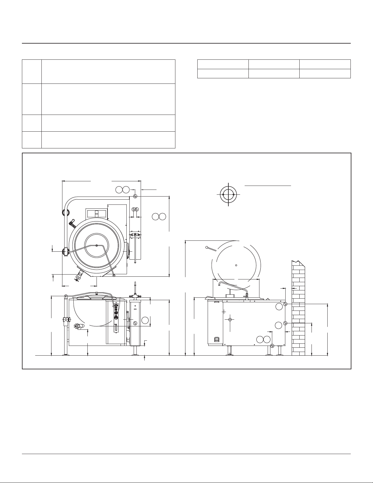
Service Connections
SERVICE CONNECTIONS
G Gas Connection - Supply gas through 3/4” pipe . A gas
shut-off valve must be installed in supply piping convenient
and adjacent to appliance.
EC Electrical Connection - Unless other wise specied,
Field Wire Electrical Connection to be 120 Volts, 60 Hertz
single phase with grounding wire. Unit furnished with 8’
cord and 3 prong plug. Total max. amps 4.0.
HW Hot Water Connection - 3/8” tubing to faucet (OP-
TIONAL)
CW Hot Water Connection - 3/8” tubing to faucet (OP-
TIONAL)
DIMENSIONS ARE IN INCHES [MM]
51 [1295]
2 [51]
3.63 [92]
H
EC
G
INSTALLATION CLEARANCE
Left Side Right Side Rear
0” [0mm] 0” [0mm] 4” [102mm]
BTU/Hour: 125,000
kW/Hour: 36.63
Gas Supply (Supply Pipe Pressure W.C.)
Natural 6”-14” (152-356mm)
Propane 11”-14” (279-356mm)
REAR FLANGED FOOT DETAIL
2 EQUALLY SPACED
Ø7/16" [11mm] HOLES
ON 2.5" [63mm] B.C.
C
* Use on non-combustible floors only.
* Shown with option faucet, cover and draw-off.
14.75
[375]
38.5
[978]
22.5 [572]
17.25 [438]
52.25
[1327]
74.5
[1892]
A
4 [102]
MINIMUM
POWER
ON
COOKING
LOW WATER
COOK TEMP.
OFF
10
9
1
8
2
7
3
6
4
5
PRESSURE
40
60
20
300
200
400
316 SS
TUBE AND CONNECTION
100
500
80
600
0
VENT AIR
kPa
psi
100
WATER LEVEL
18.75
[476]
G
36 [914]
37.75
[959]
8.5 [216]
6.38
[162]
EC
G
C
H
33.5 [891]
21
[533]
Figure 1
INSTALLATION
2
Page 5

Installation Information
INSTALLATION CODES AND STANDARDS
Installation must conform with local codes, or in the absence of local codes, with the National Fuel Gas Code,
ANSI Z223.1/NFPA 54, or the Natural Gas and Propane
Installation Code, CSA B149.1, as applicable.
1. The appliance and its individual shut off valve must
be disconnected from the gas supply piping system
during any pressure testing of that system at pressures in excess of ½ psi (3.5 kPa).
2. The appliance must be isolated from the gas supply
piping system by closing its individual manual shut off
valve during any pressure testing of the gas supply
piping system at test pressures equal to or less than
½ psi (3.5 kPa).
Electrical grounding must be provided in accordance with
local codes, or in the absence of local codes, with the
National Electrical Code, ANSI/NFPA 70, or the Canadian
Electrical Code, CSA C22.2, as applicable.
The electrical diagram is located on the inside of side
panel of left hand console.
EXHAUST FANS AND CANOPIES
Canopies are set over ranges, ovens and kettles for ventilation purposes. It is recommended that a canopy extend
6 inches past appliance and be located 7.5 feet from the
oor. Filters should be installed at an angle of 45 degrees
or more with the horizontal. This position prevents dripping of grease and facilitates collecting the run-off grease
in a drip pan, usually installed with the lter. A strong exhaust fan tends to create a vacuum in the room and may
interfere with burner performance or may extinguish pilot
ames. Makeup air openings approximately equal to the
fan area will relieve such vacuum. In case of unsatisfactory performance on any appliance, check operation with
exhaust fan in the “OFF” position.
CLEARANCES
Adequate clearance must be provided in aisle and at the
side and back. Adequate clearances for air openings into
the combustion chamber must be provided, as well as for
serviceability.
• Sides - 0 inches
• Back - 4 inches at ue box
• Floors - Non-combustible
All units must be installed in such a manner that the ow
of combustion and ventilation air are not obstructed. Pro-
visions for an adequate air supply must also be provided.
Do not obstruct side of the unit, as combustion air enters
through this area.
Information on the construction and installation of ventilating hoods may be obtained from the standard for “Vapor
Removal from Cooking Equipment”, NFPA No. 96 (latest
edition), available from the National Fire Protection Association, Batterymarch Park, Quincy, MA, USA, 02269.
ALL EXHAUST FAN
he exhaust fan should be installed at least two feet above
the vent opening at the top of the unit.
3
INSTALLATION
Page 6

Kettle Installation & Utility Connection
KETTLE INSTALLATION
1. Uncrate carefully. Report any hidden freight damage
to the freight company immediately.
2. The pressure relief valve is located at the right rear of
the unit. This area should be kept clear and should
not be in an area where operators will normally stand.
The elbow on the relief valve should be turned toward
the oor. A maximum 3 foot, 3/4” diameter pipe may
be used to extend to the oor, but must not be piped
directly to a drain. It must vent to the atmosphere.
3. Set the unit in place. Be certain to maintain minimum
clearances as stated above.
4. To level the unit use a spirit level in all directions on
the top of the kettle (lid up). Adjust the bottom foot on
each leg to overcome an uneven oor.
5. Mark hole locations on oor through anchoring holes
provided in anged adjustable feet.
6. Remove appliance and drill holes in locations marked
on oor and insert proper anchoring devices.
7. Set unit back in position and re-level left to right and
front to back.
An adequate gas supply is imperative. Undersized or low
pressure lines will restrict the volume of gas required for
satisfactory performance. A steady pressure, minimum 6”
W.C. for natural gas and minimum 11” W.C. for propane
gas, is recommended. With all units operating simultaneously, the manifold pressure on all units should not show
any appreciable drop. Fluctuations of more than 25%
on natural gas, and 10% on propane gas, will create pilot problems and affect burner operating characteristics.
Contact your gas company for correct supply line sizes.
Purge the supply line to clean out any dust, dirt, or other
foreign matter before connecting the line to the unit. It is
recommended that an individual manual shut off valve be
installed in the gas supply line to the unit. Use pipe joint
compound which is suitable for use with LP gas on all
threaded connections. Test pipe connections thoroughly
for gas leaks.
WARNING
All connections must be checked for leaks,
after the unit has been put in operation. Use
soapy water only for testing on all gases.
Never use an open ame to check for gas
leaks.
8. Bolt and anchor appliances securely to the oor.
9. Seal bolts and anged feet with silastic or equivalent
compound.
10. Appliance location must allow air supply to unit and
obstruction free clearance for air opening into the
combustion chamber.
11. Make service connections as indicated.
12. Check the pressure gauge on the front panel before
operating. If the pressure gauge does not indicate
green vacuum zone (below 0 psi), see “Re-establishing Vacuum” section under SERVICE, after completing installation instructions.
GAS CONNECTION
The serial plate on the lower right side of the unit indicates
the type of gas your unit is equipped to burn. Do NOT
connect to any other gas type.
A 3/4” NPT line is provided at the rear for the connection.
Each unit is equipped with an internal pressure regulator
which is set for 3.5” W.C. manifold pressure for natural
gas and 4.0” W.C. for propane gas. Use 1/8” pipe tap on
the downstream side of the combination valve for checking pressure.
NOTICE
If applicable, the vent line from the gas appliance pressure regulator shall be installed to
the outdoors in accordance with local codes
or, in the absence of local codes, with the National Fuel Gas Code, ANSI Z223.1/NFPA 54, or
the Natural Gas and Propane Installation Code
CSA B149.1, as applicable.
NOTICE
If this equipment is being installed at over
2,000 feet altitude and was not so specied on
order, contact service department. Failure to
install with proper orice sizing may void the
warranty.
INSTALLATION
4
Page 7

Kettle Installation & Utility Connection
WATER CONNECTION
On units equipped with an optional water ll valve connect
a water line (minimum 1/4”) to the valve with a 1/4” NPT
female tting. Units with dual (hot and cold) valves must
have the hot water line connected to side with the hot water valve (red) and cold water line to the cold water valve
(blue). Plastic or rubber hose is not recommended, as it
may melt against the hot kettle side.
ELECTRICAL CONNECTION
WARNING
Do not connect the kettle to the electrical supply until after the gas connection has been
made.
1. 120 VAC - 60 Hz - Single Phase
WARNING
ELECTRICAL GROUNDING INSTRUCTIONS
This appliance is equipped with a three-prong
(grounding) plug for your protection against
shock hazard and should be plugged directly
into a properly grounded three-prong receptacle. Do not cut or remove the grounding
prong from this plug. (120V units only).
Units with this electrical rating are factory supplied with a
three-wired cord and three-prong plug which ts any standard 120V, three-prong grounded receptacle. A separate
15 amp supply is needed for each unit.
PERFORMANCE CHECK
The following items should be checked before or within
the rst 30 days of operation by a qualied service technician.
1. Verify correct gas type against rating plate on unit.
2. Verify correct voltage, cycle and phase against rating
plate on unit.
3. Gas pressure.
4. Internal gas connections.
5. Internal electrical connections.
6. Burners - adjustment and ignition.
7. Thermostat - cycle for operation check.
8. Gas supply valve - check for operation.
9. Check hinge and lid assembly.
10. Draw-off valve - check operation.
11. Advise user on cleaning procedure.
2. 208/240 VAC - 60 Hz - Single and Three Phase
Units with this electrical rating are factory equipped with
a transformer. To connect supply wires, remove cover
from right console. Route supply wires and ground wire
through the hole in the console with a strain relief tting. Connect wires to the terminal block in the rear of
the right console. Connect ground wire to lug. Replace
cover. Three-phase units are wired as above, using only
two supply wires. The third supply wire is not connected
and must be properly terminated.
3. 220 VAC - 50 Hz - Single Phase
Units equipped with this voltage ratings should be wired
exactly as in (2.) above.
5
INSTALLATION
Page 8

Safety & Gas Control Information
SAFETY INFORMATION
Contact the factory, the factory representative or a local
service company to perform maintenance and repairs
should the appliance malfunction.
CAUTION
If you smell gas during the lighting procedure,
immediately shut off the gas supply until the
leak has been corrected.
WARNING
In the event of main burner ignition failure, a
5 minute purge period must be observed prior
to re-establishing ignition source.
WARNING
In the event you smell gas, shut down equipment at the main shut off valve and contact
the local gas company or gas supplier for
service.
GAS CONTROL INSTRUCTIONS
The units do not require “lighting” the pilot with a match.
Lighting
NOTE: Unit is shipped with gas combination valve turned
“on”.
1. Open manual gas shut off valve.
Daily Shutdown
1. Turn power switch “OFF.”
2. Turn thermostat “OFF.”
Complete Shutdown
1. Turn power switch “OFF.”
2. Turn thermostat “OFF”.
3. Turn power supply to unit “OFF”.
4. Remove front access panel on left side and turn dial
on combination valve to “OFF”.
5. Close manual gas shut off valve.
2. Set thermostat to OFF, and kettle in fully upright position, turn power switch ON.
3. Set thermostat to maximum, initiating a 30 second
pre-purge. Red “COOKING” pilot will come on, and
after 30 seconds, the green “IGNITION” pilot will
come on, lighting the main burners.
If after 36 seconds the burner fails to ignite or the
“ignition light goes out, the system goes into Safety
Lockout. De-energize the system by setting the ther-
mostat to “OFF” for ve minutes and try again.
4. Set the thermostat to desired temperature setting.
When temperature setting has been reached, the “IGNITION” pilot will go off, turning off the burner. The
unit will then cycle on and off to maintain set temperature.
NOTE: When the kettle is tilted a safety switch will au-
tomatically turn off gas supply. The kettle will not
operate once it has been tilted.
OPERATION
6
Page 9

Kettle Controls
POWER SWITCH
This switch turns the main power to the unit on and off. It
must be turned on to heat the kettle. It should be turned
off when the kettle will not be in use for long periods.
(GREED) IGNITION LIGHT
This light is on whenever the main burner gas is on.
(RED) COOKING LIGHT
This light is on when the thermostat is calling for heat.
(AMBER) LOW WATER LIGHT
All kettles are supplied with sufcient distilled water in
pressurized jacket. If at any time the water level falls be-
low that required for proper operation, the kettle will not
heat and this light will come on. See “Adding Water” in
Service section.
THERMOSTAT
The thermostat selects the desired internal kettle operating temperature. The thermostat must be set at a desired
setting in order for the burner to ignite.
For Reference:
PRESSURE GAUGE
The pressure gauge indicates the internal operating pressure of the kettle. When cold, the gauge should point to
the green vacuum zone. If it does not, refer to “Re-establishing Vacuum” section. Under normal operation with the
kettle empty (thermostat set at 10 or 275°F) the pressure
should reach 30 psi. When loaded the pressure may be
considerably less.
SIGHT GLASS
The sight glass indicates the minimum and maximum water level within the kettle. If water level falls below minimum level more distilled water should be added. See
“Adding Water” in Service section.
PRESSURE RELIEF VALVE
The pressure relief valve is a safety device which prevents the internal kettle pressure from exceeding 50 psi.
It should never be tampered with.
DIAL SETTING °C °F
1 15 60
2 27 81
3 40 104
4 53 127
5 67 153
6 81 178
7 95 203
8 108 226
9 122 252
10 135 275
7
MAINTENANCE
Page 10

Kettle Operation
DAILY OPERATION
Daily operation should consist of turning on the power
switch and setting thermostat for the desired temperature.
It is recommended the kettle be preheated prior to use.
Milk or egg based products should be placed in the kettle
before heating however, to prevent sticking. The kettle is
preheated when the cooking light goes off the rst time.
At the end of the day, or if the kettle will not be used for
some time, shut the unit down by turning the power switch
to “OFF”.
Clean as required or on a daily basis. See “CLEANING
INSTRUCTIONS” section.
END USE TIPS
• For easier cleaning add cold water to the kettle immediately after removing contents.
• When preparing foods containing vinegar or tomatoes, or those which have a high salt content, clean
the kettle immediately after using to prevent pitting.
• Do not use salt to clean the kettle. This will scratch
the surface.
GAS SAVING TIPS
Use these reminders to help develop energy-saving procedures and habits. Using less natural or propane gas
saves energy as well as money.
1. Turn off when not in use.
2. Limit preheat times.
3. Use lid when possible.
4. Maintain equipment.
• If using salt water to cook shellsh, be sure to rinse
and wash the kettle thoroughly after use.
• Bring milk and egg products slowly up to temperature in a cold kettle to prevent product from adhering
to the sides. When preparing milk-based products
do not preheat the kettle.
• When planning actual cooking capacity, allow room
at top for stirring without spilling.
• When preparing puddings from a mix, place the
powder in a cold kettle, add a small amount of liquid,
and stir to form a thin paste. Turn on the kettle and
add the remainder of the liquid. Continue as per
recipe instructions.
• When browning meat, bring the kettle up to temperature before adding. This will seal the juices in the
meat.
OPERATION
8
Page 11

Cleaning Instructions
KETTLE CLEANING
WARNING
Disconnect the power supply to the appliance
before cleaning or servicing.
WARNING
Never spray water into electric controls or
components!
CAUTION
The equipment and its parts are hot. Use care
when operating, cleaning and servicing.
CAUTION
Do not use cleaning agents that are corrosive.
Your kettle should be cleaned immediately after each use
or when cooking a different product. Before cleaning,
check that the kettle has cooled enough to touch it.
1. Rinse the inside of the kettle thoroughly and drain to
remove any food particles.
2. Using a nylon brush, clean the kettle with a mild detergent and water. Never use steel wool or scouring
powder as it will scratch stainless steel. Plain steel
wool can leave small pieces of steel which can rust.
3. Rinse the inside of the kettle thoroughly with clean
water. Drain the kettle by tilting or the tangent drawoff valve, depending on model, to allow the detergent
and water solution to drain.
4. Wipe the exterior of the kettle with a clean, damp
cloth.
DRAW OFF VALVE CLEANING
1. If equipped with a tangent draw-off valve, turn the
large hex nut on the draw-off valve counterclockwise
until it is completely disengaged from the threads.
Grasp the valve knob and slowly pull out the valve
stem and disk. Do not allow the disk to come in contact with hard surfaces as it can be damaged and
cause valve leakage. Wash the valve stem, disk and
handle. Insert a nylon brush, wet with detergent and
water, into the valve body and tangent draw-off tube.
Brush vigorously.
2. Replace the valve stem assembly and turn the hex
nut until snug. Rinse the kettle with clean warm water.
3. Leave the draw-off valve open when the kettle is not
in use.
Dairy Draw Off Valve Cleaning
1. Remove the plug by rst removing the handle, then
turn the plug to line up with the pin and pull with both
hands. It is important to use both hands because the
plug is heavy.
2. Put the plug in a plastic pail that contains a mild soap
solution. A plastic pail works best, as it reduces the
possibility of nicking or scratching the plug. If the plug
gets scratched it may not seal correctly and could
leak.
3. Use a soft cloth or soft brush and clean all surfaces.
4. Using both hands remove the valve from the soap
and rinse well in another plastic pail that contains
fresh water.
5. Wash out the kettle as normal.
WARNING
If you are cleaning a valve that is assembled
to a kettle, be sure the kettle is completely
empty of any product.
6. Once the kettle is washed out, return the plug into the
body. Be sure the plug is inserted into the notch and
turned. Ensure the plug is tight and secure before
letting go of it.
If you are cleaning a body and plug assembly, remove
the plug and follow the above procedures. When nished
with the plug, follow the same instructions for washing the
body. Always use both hands when handling the plugs.
Reassemble the plug into the body and use as normal.
NOTICE
Draw-off valve has a vulcanized rubber coated
stem for better sealing. Do not over tighten.
This may cause the rubber to pull away from
stem and permanently damage it. This is not
covered under warranty.
9
MAINTENANCE
Page 12

Cleaning Instructions
WHAT TO DO IF SURFACE RUST APPEARS
Metal utensils should never be used as they will scratch
the surface of the equipment and rust may begin to form.
To remove surface accumulation of rust from the inadvertent use of such utensils, the following procedure may be
used.
CAUTION
Improper use of this procedure may damage
your appliance!
1. Use undiluted white vinegar with a non-abrasive
scouring pad (plastic) or cloth on the affected area to
remove the rust stain. The appliance should not be
heated and remain at room temperature during the
entire cleaning process.
2. If the stain resists removal, additional exposure time
with vinegar may be required, to a maximum of one
hour.
3. Thoroughly wash all of the vinegar away with fresh
clear water. Dry the surface completely and allow one
hour before using the appliance to cook.
Following daily and period maintenance procedures will
prolong the life for your equipment. Climatic conditions salt air - may require more thorough and frequent cleaning
or the life of the equipment could be adversely affected.
STAINLESS STEEL
To remove normal dirt, grease or product residue from
stainless steel, use ordinary soap and water (with or without detergent) applied with a sponge or cloth. Dry thoroughly with a clean cloth. Never use vinegar or any other
corrosive cleaner.
To remove grease and food splatters or condensed va-
pours that have baked on the equipment, apply cleanser
to a damp cloth or sponge and rub cleanser on the metal
in the direction of the polishing lines. Rubbing cleanser
as gently as possible in the direction of the polished lines
will not mar the nish of the stainless steel. NEVER RUB
WITH A CIRCULAR MOTION.
Soil and burn deposits which do not respond to the above
procedure can usually be removed by rubbing the surface
with SCOTCH-BRITE™ scouring pads or STAINLESS
scouring pads. DO NOT USE ORDINARY STEEL WOOL
as any particles left on the surface will rust and further
spoil the appearance of the nish. NEVER USE A WIRE
BRUSH, STEEL SCOURING PADS (EXCEPT STAINLESS), SCRAPER, FILE OR OTHER STEEL TOOLS.
Surfaces which are marred collect dirt more rapidly and
become more difcult to clean. Marring also increases
the possibility of corrosive attack. Renishing may then
be required.
To remove heat tint: Darkened areas sometimes appear on stainless steel surfaces where the area has been
subjected to excessive heat. These darkened areas are
caused by thickening of the protective surface of the
stainless steel and is not harmful. Heat tint can normally
be removed by the foregoing, but tint which does not respond to this procedure calls for a vigorous scouring in
the direction of the polish lines using SCOTCH-BRITE™
scouring pads or a STAINLESS scouring pad in combination with a powdered cleanser. Heat tint action may be
lessened by not applying or by reducing heat to equipment during slack periods.
All food contact surfaces must be thoroughly drained and
ushed prior to cooking in the kettle.
CONTROL PANEL
The textured control panel should be cleaned with warm
water and mild soap. Never use an abrasive cloth or steel
wool. Never use cleaning solvents with a hydrocarbon
base.
MAINTENANCE
10
Page 13

Contact the factory, the factory representative or a local
service company to perform maintenance and repairs.
WARNING
Disconnect the power supply to the appliance
before cleaning or servicing.
Daily:
1. Wash exposed cleanable areas.
Monthly:
1. Blower wheel inlet and motor air vent should be
cleansed if an accumulation of dust or lint is obvious.
Twice a Year: (minimum)
1. Have an authorized service person clean and adjust
the unit for maximum performance.
2. The unit venting system should be examined and
cleaned.
3. Grease the screw jack tilt mechanism via the lubricating nipple. Use Petro-Canada type OG-2 or equivalent.
Preventative Maintenance
Annually:
1. Have an authorized service person inspect the screw
jack assembly for wear. The screw must be replaced
immediately if the end play has reached 0.019”
[0.5mm].
11
MAINTENANCE
 Loading...