

Page 1
®
IMV-4E
INSTALLATION - OPERATION - MAINTENANCE
NSF/ANSI 4
E538399
E538398
BLODGETT OVEN COMPANY
www.blodgett.com
42 Allen Martin Drive, Essex Junction, Vermont 05452 USA Telephone: (802) 658-6600 Fax: (802) 864-0183
PN 110548 Rev B (2/25)
© 2024 - G.S. Blodgett Corporation
Page 2

Your Service Agency’s Address:
Model
Serial number
Oven installed by
Installation checked by
Page 3

IMPORTANT
Table of Contents
WARNING: Improper installation, adjustment, alternation,
service or maintenance can
cause property damage, injury or death. Read the instllation, operation and maintenance instructions thoroughly
before installing or servicing
this equipment.
INSTRUCTIONS TO BE FOLLOWED IN THE EVENT THE
USER SMELLS GAS MUST BE
POSTED IN A PROMINENT LOCATION. This information may
be obtained by contacting your
local gas supplier.
FOR YOUR SAFETY
Do not store or use gasoline or
other ammable vapors or liquids in the vicinity of this or any
other appliance.
INSTALLATION
Oven Description & Specications ....................................................................... 2
Utility Connections - Standards and Codes .......................................................... 4
Oven Location ...................................................................................................... 5
Electrical Connections .......................................................................................... 6
OPERATION
Safety Information ................................................................................................ 7
ImVection Touchscreen Control ............................................................................ 8
MAINTENANCE
Cleaning and Preventive Maintenance ............................................................... 34
The information contained in this
manual is important for the proper installation, use, and maintenance of this oven. Adherence
to these procedures and instructions will result in satisfactory
baking results and long, trouble free service. Please read
this manual carefully and retain
it for future reference.
ERRORS: Descriptive, typographic or pictorial errors are
subject to correction. Specications are subject to change
without notice.
Page 4

Installation
Oven Description & Specications
ABOUT THE IMVECTION
Blodgett ImVection ovens are quality produced using
high-grade stainless steel with rst class workmanship.
The multiple speed fan, which is guarded against
accidental nger contact, is driven by a quiet and powerful
motor.
The use of high quality insulation impedes excessive heat
radiation and saves energy.
The ImVection has optional adjustable feet which adapt
easily to slightly uneven surfaces and optional oor
stands.
The practical oven doors, with viewing windows, have
a wide swing radius and handle which can be operated
easily, even with wet or greasy hands.
Ease of operation is guaranteed through the simple
arrangement of the controls. Graphic symbols make the
appliance easy for even inexperienced kitchen sta to
operate.
Cleaning is kept to a minimum. The interior is sprayed
with a self-acting cleaning solution to easily remove crusts
and stains.
2
Page 5

Installation
Oven Description & Specications
RATINGS- IMV-4E
VOLTAGE
208-240 60 17.5 3 42 42 49
HZ
KW
PHASE
MAX LOAD (AMPS)
L1 L2 L2
3
Page 6
Installation
Utility Connections - Standards and Codes
THE INSTALLATION INSTRUCTIONS CONTAINED
HEREIN ARE FOR THE USE OF QUALIFIED INSTALLATION AND SERVICE PERSONNEL ONLY. INSTALLATION OR SERVICE BY OTHER THAN QUALIFIED
PERSONNEL MAY RESULT IN DAMAGE TO THE OVEN
AND/OR INJURY TO THE OPERATOR.
Qualied installation personnel are individuals, a rm,
a corporation, or a company which either in person or
through a representative are engaged in, and are responsible for:
• The installation or replacement of gas piping. The
connection, installation, repair or servicing of equipment.
• The installation of electrical wiring from the electric
meter, main control box or service outlet to the electric appliance.
Qualied installation personnel must be experienced in
such work, be familiar with all precautions required and
have complied with all requirements of state or local au-
thorities having jurisdiction.
U.S. and Canadian Installations
Installation must conform with local codes, or in the absence of local codes, with the National Fuel Gas Code,
NFPA54/ANSI Z223.1-Latest Edition, the Natural Gas Installation Code CAN/CGA-B149.1 or the Propane Installation Code, CAN/CGA-B149.2 as applicable.
Reference: National Electrical Code, ANSI/NFPA 70-Latest Edition and/or Canadian Electrical Code CSA C22.1
as applicable.
This equipment is to be installed in compliance with the
Basic Plumbing Code of the Building Ocials and Code
Administrators International Inc. (BOCA) and the Food
Service Sanitation Manual of the Food and Drug Administration (FDA).
General Export Installations
Installation must conform with Local and National instal-
lation standards. Local installation codes and/or requirements may vary. If you have any questions regarding the
proper installation and/or operation of your appliance,
please contact your local distributor. If you do not have
a local distributor, please call Blodgett at 0011-802-658-
6600.
NSF/ANSI 4
E538399
E538398
4
Page 7

OWNER’S RESPONSIBILITIES
Installation responsibilities prior to service startup inspection
You are entitled to a free start-up inspection service by
our factory ASAP. Before a factory representative arrives
to perform a startup procedure, the owner must already
have satised the following requirements.
1. Oven(s) are uncrated and put in place.
OVEN LOCATION
The well planned and proper placement of your oven will
result in long term operator convenience and satisfactory
performance.
Certain minimum clearances must be maintained between the oven and any combustible or non-combustible
construction. See the table below.
In addition, the following clearances are recommended
for servicing.
• Oven body sides - 12” (30cm)
Installation
Oven Location
• Oven body back - 12” (30cm)
OVEN
MODEL
IMV-4E 4”
• Do not place strong sources of heat such as open
ame ranges, griddles, or charbroilers near the
oven.
• Note that if temperatures are too high, a safety shutdown may occur.
• Failure to comply may invalidate the oven warranty.
MINIMUM REQUIRED CLEARANCES
Right Side Left Side Back
(101.6mm)
4”
(101.6mm)
2”
(50.8mm)
5
Page 8

Installation
Attachment
LEG OPTIONS
Figure 1
STAND OPTION
1. Follow the instructions provided in the ImVection
stand kit.
ATTACHMENT
1. Elevate the oven by lifting either the front or the back
of the unit.
2. Align the threaded stud of the leg with the bolt hole
on the bottom of the unit and turn the leg until fully
installed.
3. Repeat for each leg.
4. Adjust the legs until the unit is level by extending the
bottom portion of the leg.
Figure 2
6
Page 9

ALL MODELS
NOTE: Electrical connections must be performed by a
qualied installer only.
Before making any electrical connections to these appli-
ances, check that the power supply is adequate for the
voltage, amperage, and phase requirements stated on
the rating name plate mounted on the appliance.
The circuit breaker that is used to provide power to this
appliance must have a minimum of .076” (3mm) contact
spacing. The circuit breaker must meet all Local and National installation standards.
All appliances must be installed in accordance with Local
or National Electrical codes.
This appliance uses a variable frequency drive, which can
be known to produce high frequency electrical noise. In
some cases units must be hard wired. This avoids false
positives on ground fault devices susceptible to errors
from electrical noise. All installations must comply with local and national codes.
A wiring schematic is located on the inside of the removeable top panel.
NOTE: Disconnect the power supply to the appliance
before servicing.
Installation
Electrical Connections
WARNING!!
If the supply cord is damaged, it must be replaced by a special cord or assembly available
from the manufacturer or its service agent.
WARNING!!
Improper installation may invalidate your warranty.
7
Page 10

Operation
Safety Information
The information contained in this section is provided for
the use of qualied operating personnel. Qualied operating personnel are those who have carefully read the information contained in this manual, are familiar with the
functions of the oven and/or have had previous experience with the operation of the equipment described. Adherence to the procedures recommended herein will assure the achievement of optimum performance and long,
trouble-free service.
Please take the time to read the following safety and
operating instructions. They are the key to the successful operation of your Blodgett oven.
SAFETY TIPS
For your safety read before operating
What to do in the event of a power failure:
• Turn all switches to o.
• DO NOT attempt to operate the appliance until the
power is restored.
NOTE: In the event of a shut-down of any kind, allow a
ve (5) minute shut o period before attempting
to restart the oven.
8
Page 11
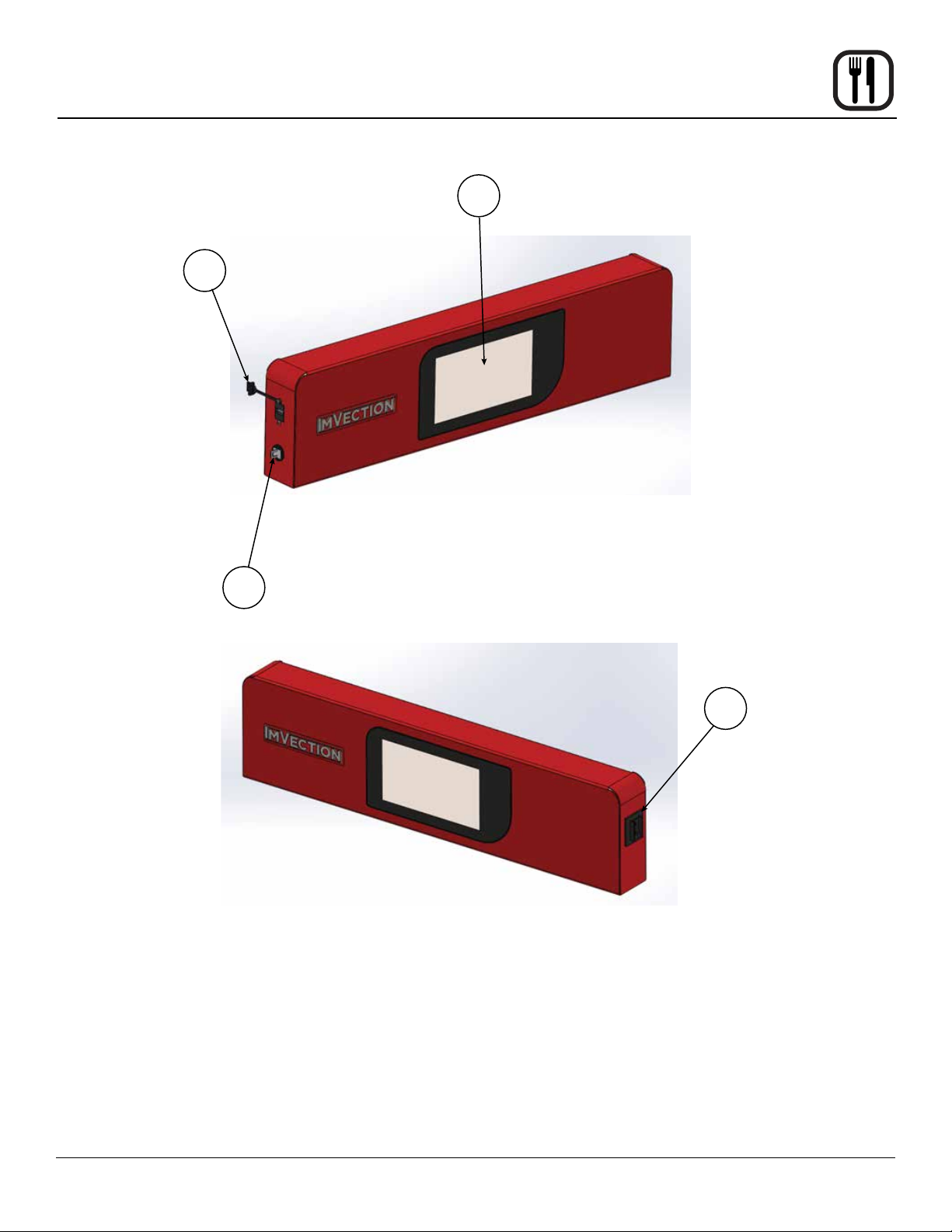
ImVection Touchscreen Control
1
Operation
3
2
4
1. USB Port and Cover - Use to transfer recipes and data to/from the control.
2. Core Probe Connection Cover - Plug core temperature probe in here when using probe cooking.
3. Touchscreen - Interactive display for oven operation and programming.
4. Circuit Breaker - Provides circuit protection for the oven controls. DO NOT use as a power switch.
9
Page 12
Operation
ImVection Touchscreen Control
HOW TO USE THE CONTROL
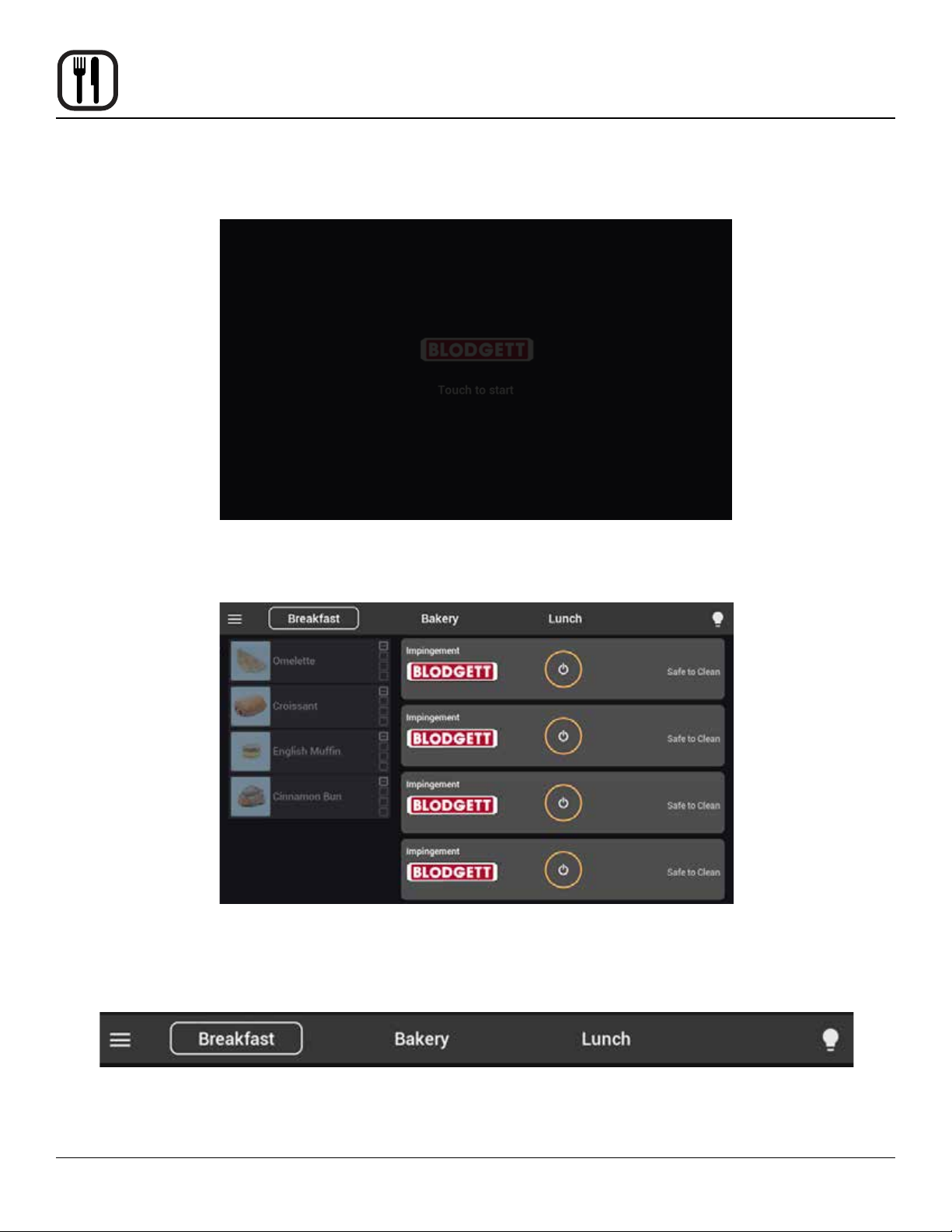
If the oven is o, or if all chambers are idling, the screen will dim and present the Blodgett
logo. Touch the screen to wake the control to the home screen.
The home screen is the recipe cooking mode. The top bar of the screen lists the currently
available recipe groups. Each group has predened chamber temperatures and a
selection of recipes catered to cooking at the predened temperatures. Select any of
these listings at the top of the screen to change your current recipe group.
10
Page 13
Operation
ImVection Touchscreen Control
Notes:
• It is possible to have more groups than can be simultaneously displayed in the top bar. This area can be
scrolled left to right to view additional groups.
• Groups cannot be changed while the unit is actively cooking product aliated with the currently selected
group.
• Dierent groups may have dierent chamber temperatures. If chambers have been powered on under a
specic group, they may require time to heat or cool to get to the new group’s desired state.
The recipes of the currently selected group are listed down the left side of the display. If there are more
recipes in a group than can be displayed in this eld, the left section may be scrolled top to bottom to view
additional recipes.
Once the desired group has been selected, press the power key on any chamber to begin heating that
chamber to its predened group setpoint. Any combination of available chambers may be powered on at
any given time.
11
Page 14
Operation
ImVection Touchscreen Control
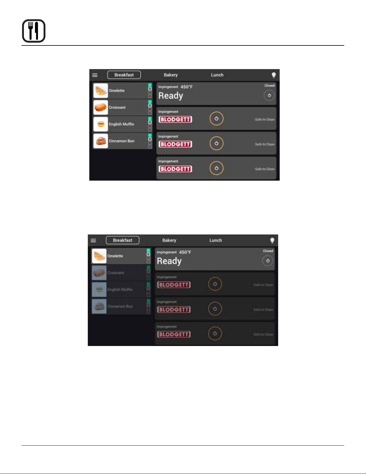
Once preheating is complete the unit will briey stabilize the temperature before
presenting the Ready status. Once a chamber is ready any recipe item with compatible
settings will become illuminated allowing it to be selected for assignment to a chamber.
Recipes which use the core probe cooking function will only illuminate when the chamber
is prepared, and the probe has been plugged into the port on the left side of the control
panel.
Once a recipe has been selected the applicable chamber light will begin to ash,
indicating where to place the product. If the door is opened to this chamber the recipe
item will automatically assign to that chamber and begin the timer once the door closes.
A recipe may be assigned to a chamber after insertion by selecting the recipe then
selecting the chamber position on the screen.
Note: If a recipe can be cooked in multiple chambers, it will always position itself to be on
the topmost appliable chamber position.
12
Page 15
ImVection Touchscreen Control
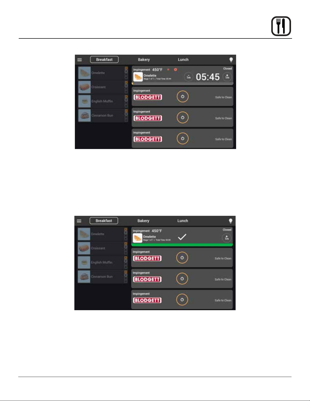
Once a recipe has been initiated, it will automatically progress through the dened cook
stages. The timer may be paused by selecting the || icon or opening the door of that
chamber.
Note: chamber heating does not cease when the pause button is selected, only the timer is
paused.
A recipe may be cancelled by selecting the X icon. Pressing the -1m key will subtract one
minute from the current cook stage. Pressing the +1m key will add one minute to the current
cook stage.
Operation
When a recipe has completed, an alarm will sound, the chamber light will begin ashing
and the chamber position will show a green progress bar with a check mark. If the product
needs additional time, the +1m key will still be available for selection. Selecting the chamber
recipe or opening the chamber door will remove the recipe from the onscreen chamber
position, freeing it for the next product assignment.
13
Page 16
Operation
ImVection Touchscreen Control
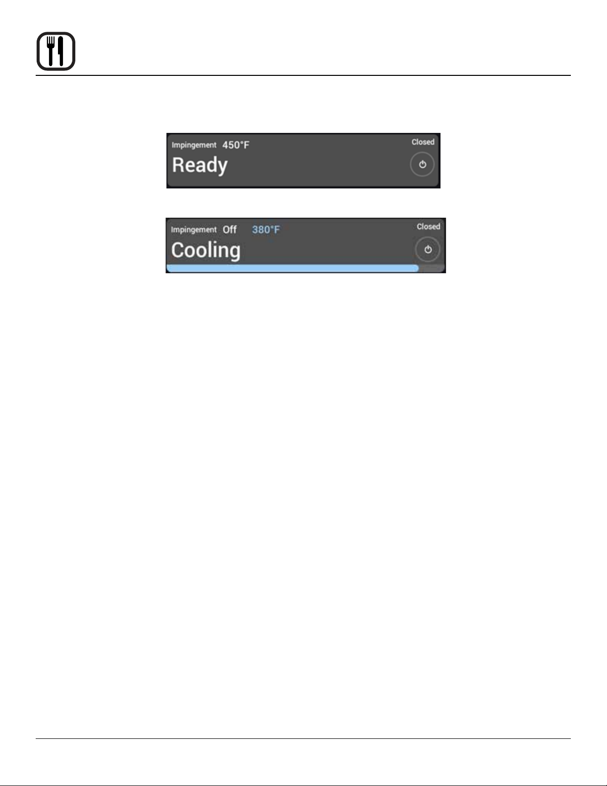
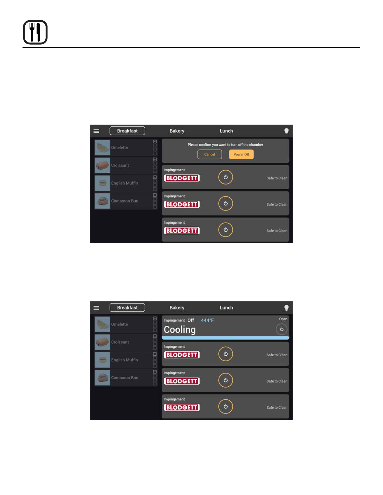
To turn o a chamber, ensure there is no active product in that chamber, and select the
power key to the right side of the chamber eld. The chamber will begin cooling and auto-
matically shutdown once it has achieved a safe temperature.
14
Page 17
Operation
ImVectionTouchscreen Control
CREATING & EDITING RECIPES
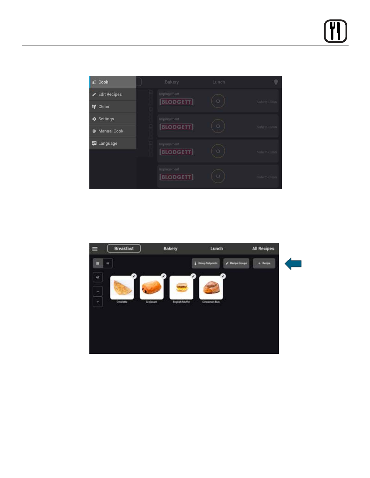
From the home screen select the menu icon from the top left corner of the screen. On the menu
that appears select Edit Recipes. This will bring you to the recipe screen for the currently selected
group.
To create a new recipe, select the + Recipe key in the upper right corner of the screen.
15
Page 18
Operation
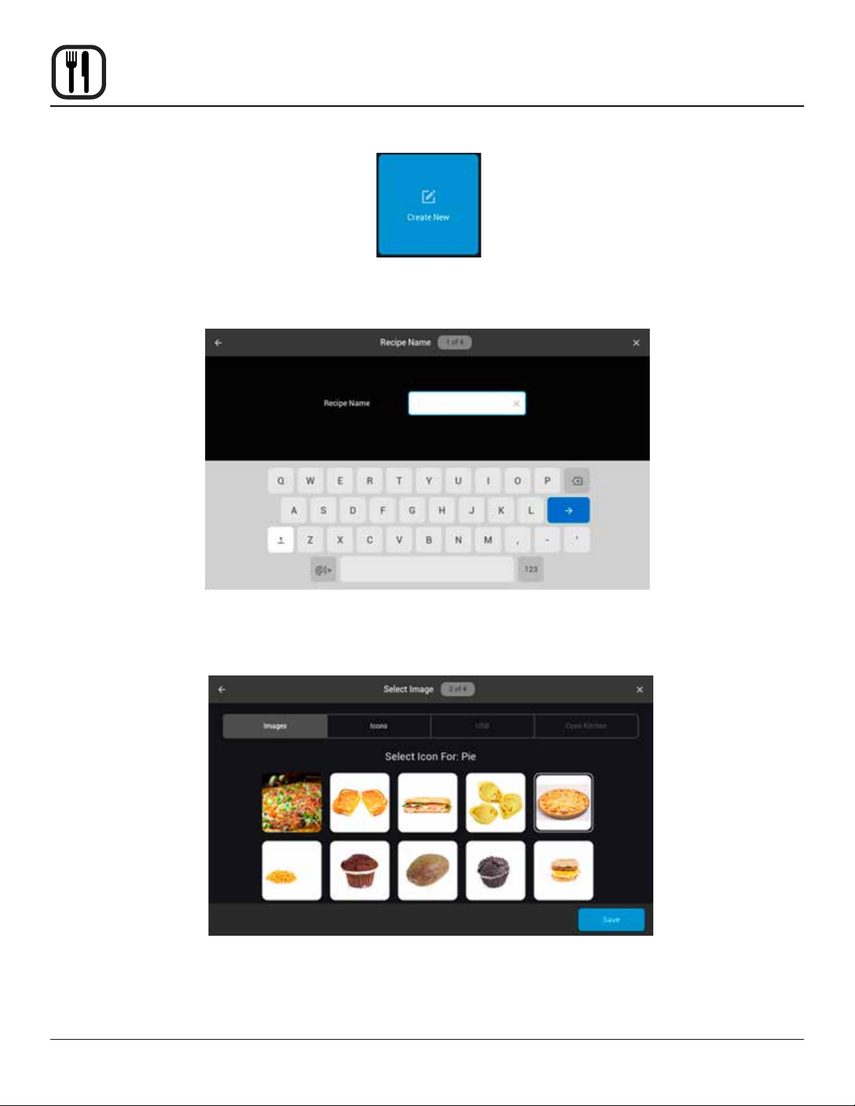
From the Add Recipe screen, select Create New.
ImVection Touchscreen Control
You’ll be prompted to enter a name for your recipe. Select the right arrow key to save
your recipe name and progress.
Next you will be prompted to select an image for your recipe. You can select which image
library you wish from those illuminated at the top of the page (Images, Icons, USB photos, Open Kitchen) When the desired image has been selected, press save to progress
to the Cook Settings page.
Note: Icons may also be assigned 1 of 12 color options
16
Page 19
ImVection Touchscreen Control
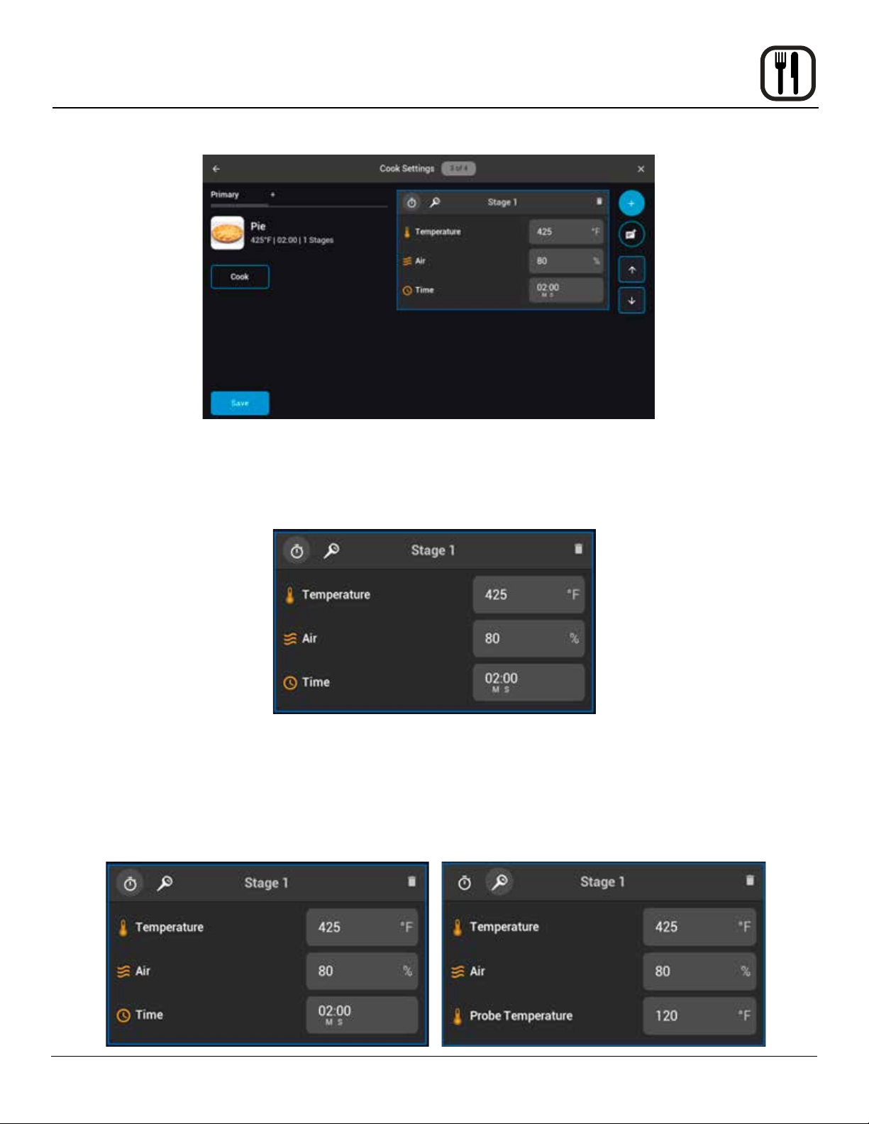
Initially you will be presented with one cooking stage. A recipe can be designed to be
complete based on a timer, by achieving a specic internal core temperature measured
with the unit’s product probe, or a combination of the two. Selecting the Stopwatch or
Probe icon at the top of the stage eld will dene if it is a timed or probe-based cook
stage.
Operation
Selecting the Temperature eld will dene the recipe cook temperature. Any temperature
below 400° will automatically set the unit to utilize Convection airow, any temperature
400° or above will automatically set the unit to utilize Impingement airow. Only the rst
stage of a recipe may have its temperature dened, all subsequent stages will maintain
the stage one temperature.
Selecting the Air eld will allow you to dene the percentage of max fan speed for this
stage of cooking.
17
Page 20
Operation
ImVection Touchscreen Control
If doing a timed stage, the Time eld will allow you to dene the duration in minutes and
seconds. If doing a probe cooking stage, the Probe Temperature eld will allow you to
dene the internal product temperature at which the stage will be considered done.
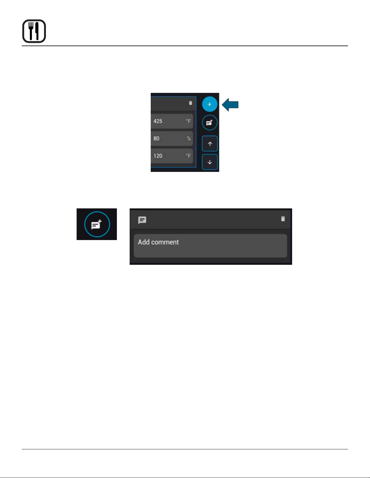
Additional stages may be added to the recipe by selecting the + key in the upper right
corner of the screen.
Comment stages can be added to the recipe by selecting the + Message icon just below
the + key. Comment stages are customizable notes that can be placed in recipes, such
as instructions to stir or add sauce.
If multiple stages are featured in a recipe, the currently selected stage will be outlined in
blue. The position of the currently selected stage may be moved up or down in the stage
progression by using the arrow keys at the right of the screen.
To delete a recipe stage, select the Trash icon in the top right of the stage window.
Note: Recipes must contain at least 1 stage. Each stage has a max duration of 59:59
(mm:ss)
18
Page 21
ImVection Touchscreen Control
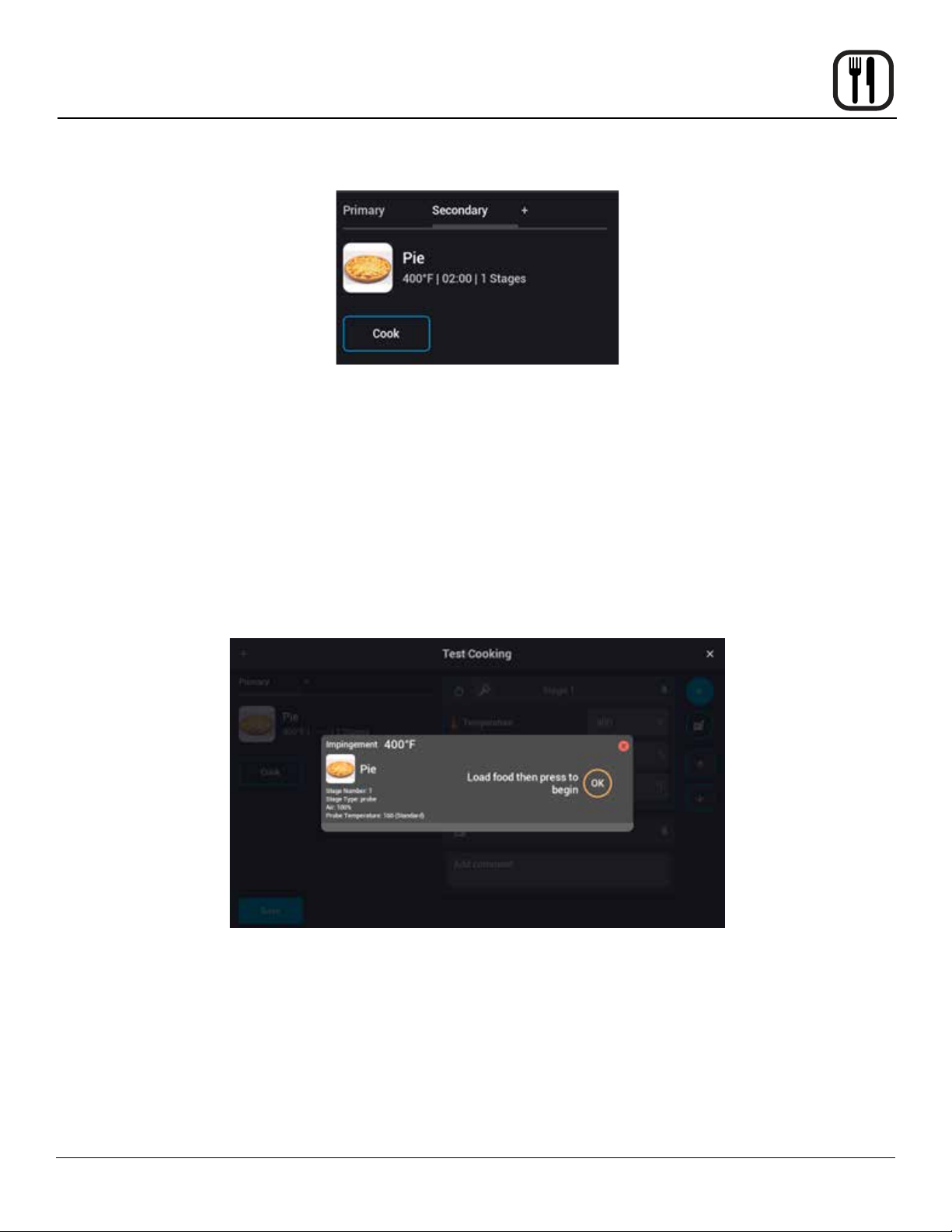
Primary Secondary and Tertiary options
In the upper left corner of the cook settings screen, you’ll note there is the word Primary
with a +, selecting this + icon will add a Secondary recipe conguration and bring you to
the settings window for that conguration. A secondary (or tertiary) conguration allows
you to dene an entirely dierent recipe setting prole for a product under the same
name. This is to allow a singular product to be available in multiple chambers (set temperatures), groups, or cook modes, for options with regards to convenience, accessibility,
and quality.
Ex. A pie might cook best (primary settings) at 400° for 10 minutes but can also be
cooked at 350° for 13 minutes (secondary). This additional option would allow for it to be
cooked in a chamber of either setpoint.
Operation
Test Cook
The Cook key on the left side of the Cook Settings screen will allow you to prepare a
chamber for a test bake of the product currently being edited. Once the chamber has
reached setpoint, you will be prompted to insert the product and start the test bake.
When all the desired cook settings have been dened, select Save in the lower left
corner to proceed to the group selection menu.
19
Page 22
Operation
ImVection Touchscreen Control
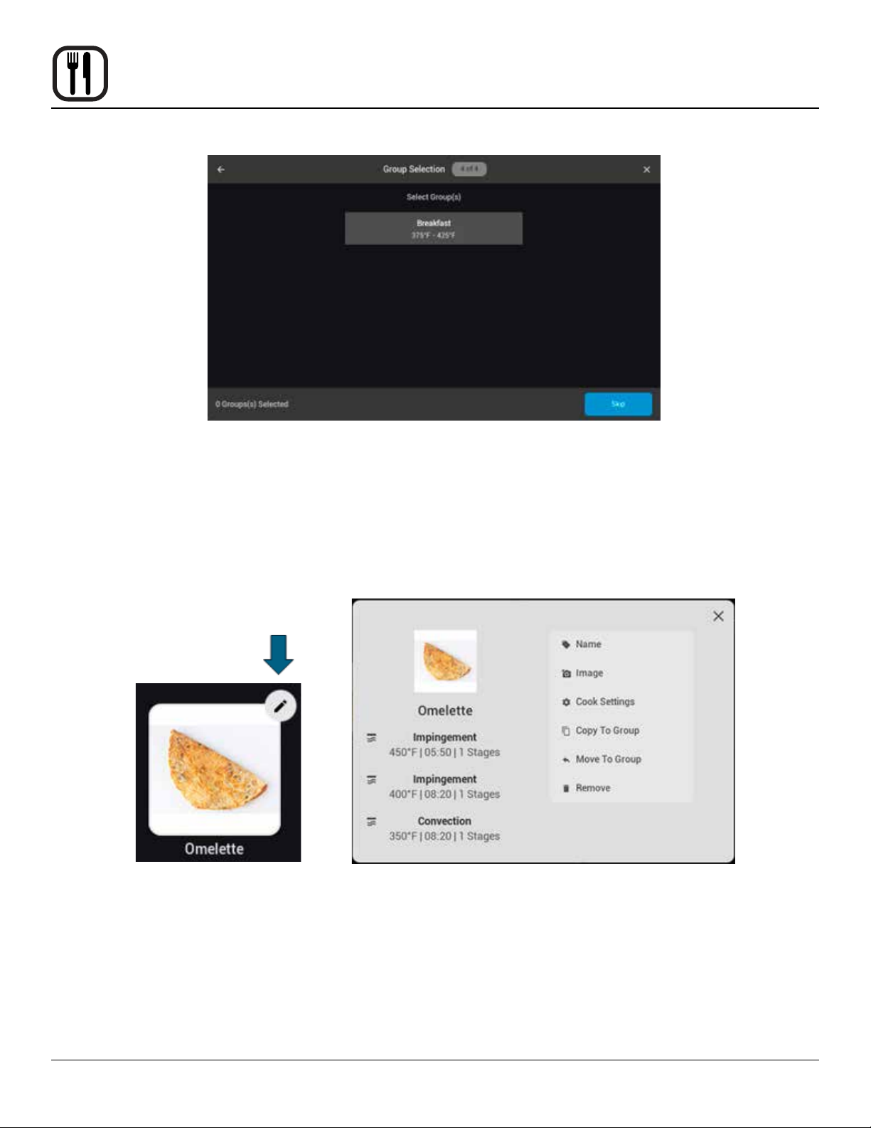
The group selection menu will display all groups that have chamber settings capable of
cooking at least one of the recipe settings proles dened in the previous screen. You
can select any number of these groups to add your newly created recipe to or select skip
to add the recipe to the All Recipes listing for later assignment to a group.
EDITING A RECIPE
While viewing the recipe libraries in the edit recipes menu you may select the pencil icon
in the top right of any of the recipe icons to edit that recipe. This will open a menu allowing you to revise the name, image, or settings of the recipe. See Recipe Creation for
more details on any of these features. Additionally, you will have the option to copy or
move the recipe amongst groups.
20
Page 23
Operation
ImVection Touchscreen Control
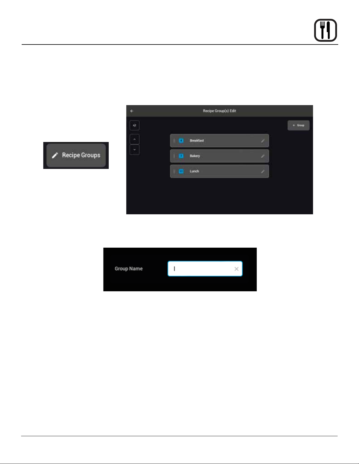
CREATING A RECIPE GROUP
All recipes must be assigned to a group to be cooked in the recipe cooking mode. Recipe groups
dene the temperature setpoints for each of the 4 chambers and allow assignment of recipes that
share a temperature setting within the tolerance band of at least one chamber.
To create a recipe group, select the recipe groups key featuring a pencil in the upper right of the
recipe editing menu. A listing of any current groups will be presented, select the + Group key in
the upper right corner to create a new group.
You will be prompted to enter the name of the group. The group name is the heading that will
appear atop the recipe cook mode screen. When you’ve entered a name, select the right arrow
key to save and proceed.
21
Page 24
Operation
ImVection Touchscreen Control
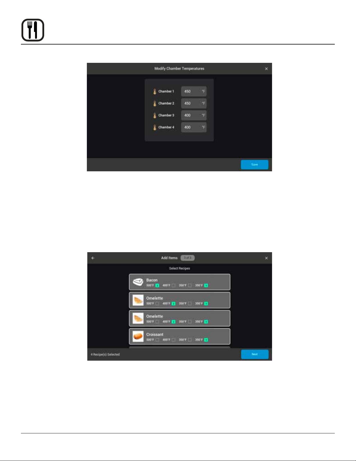
Next you will be asked to dene the setpoint of each chamber. Each chamber may be
set for to any temperature between 300°F – 525°F. If each chamber is to be at a dierent
temperature, it is suggested to have the hottest chamber at the top (chamber 1) and
descend with the coolest on the bottom chamber (chamber 4). If a group is not initially
setup in this manner, it will be automatically reordered when progressing to the next step.
It is also recommended that no two adjacent chambers have a dierence greater than
175°F for optimal performance.
When all chambers’ temperatures have been dened select Save from the lower right
corner of the screen.
The last step of group creation is to select the recipes that will be included in the group.
All recipes applicable to one or more of the chambers will be presented for selection. A
green box with a number (1-3) will show up next to each relevant chamber temperature.
The number denotes if that cavity is compatible with the primary, secondary, or tertiary
recipe settings prole. When you’ve selected all the recipes that you would like to include
in the new group select Next from the lower right corner or the screen. A summary of
the group setup will be presented, select Save to nalize group creation. A group must
contain at least one recipe to be saved.
22
Page 25
ImVection Touchscreen Control
CREATING A RECIPE GROUP
Operation
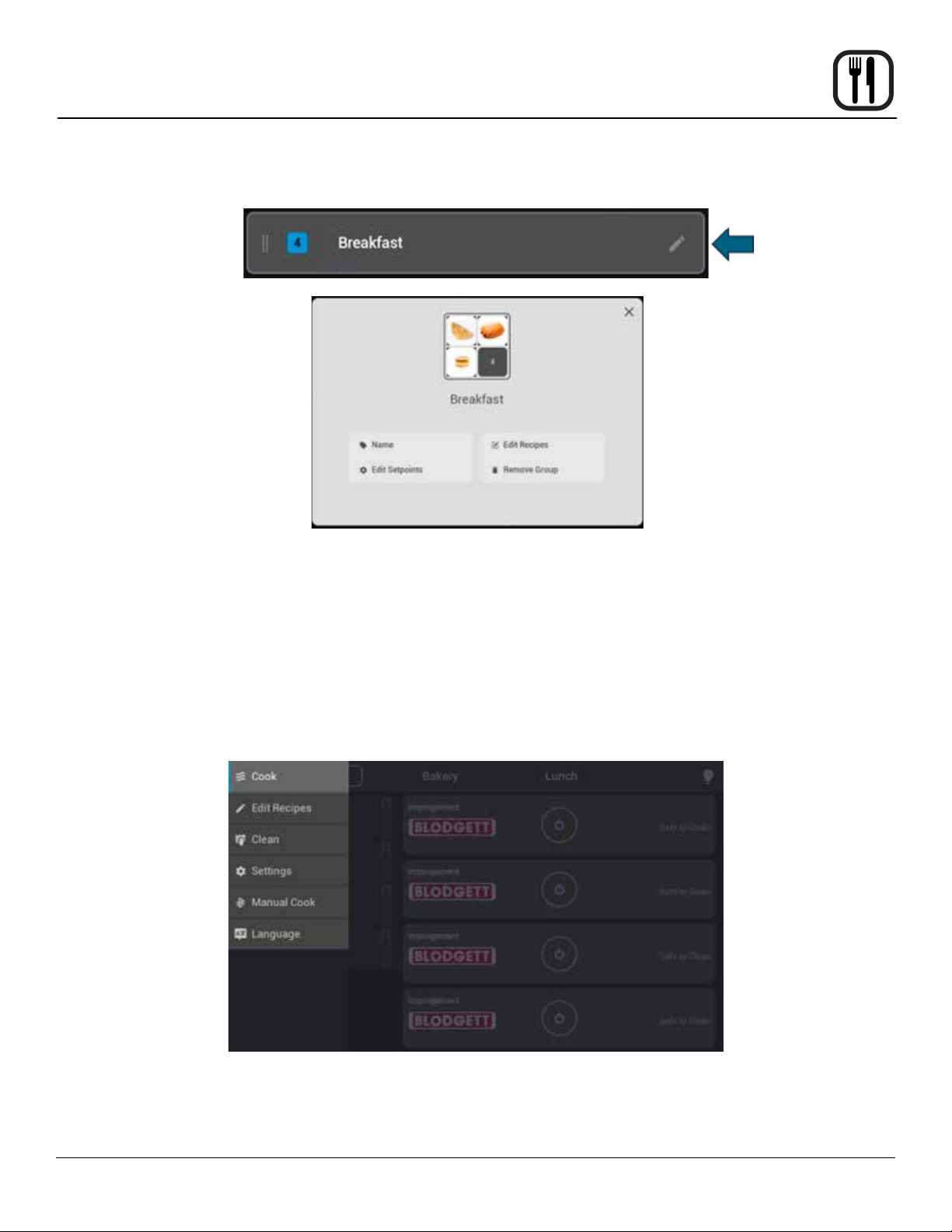
From the Edit Recipes menu select the recipe groups key featuring a pencil
in the upper right of the screen. In the recipe Group(s) Edit Menu you will
see a listing of all current groups. You may select the pencil icon to the right
of any group title to edit that group (Name, Setpoints, Recipes, or Removal).
You may also reorder the groups using a drag and drop (drag from the right
side of the group bar) or the arrow keys at the left of the screen. There is
also the option to sort groups alphabetically. The ordering of the groups (top
to bottom) is how they will be displayed left to right in the cooking menu.
MANUAL COOKING
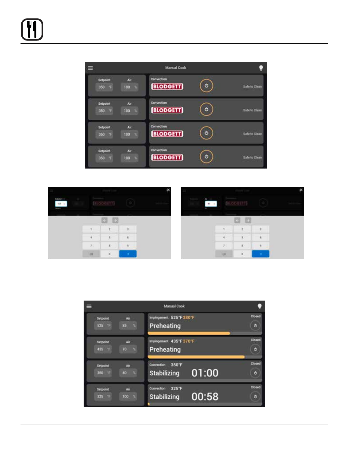
To cook without a recipe or group, select the menu icon from the top left corner of the screen. On the menu that appears select Manual Cook.
23
Page 26
Operation
ImVection Touchscreen Control
In the manual cooking mode, you can dene temperature and fan settings for each
chamber. Once heated, a timer or core probe temperature target can be dened.
To establish the settings for a chamber, select the Setpoint eld. The temperature can
be set between 300°F (149°C) and 525°F (273°C). Chambers 400°F (205°C) and above
will utilize impingement technology, whereas those below will use convection airow.
Selecting the right arrow will save the setting and transition you to dening the Air
percentage (fan speed).
When nished setting up the temperature and fan speed for the chamber(s), press the power key(s) to
begin the preheating.
24
Page 27
ImVection Touchscreen Control
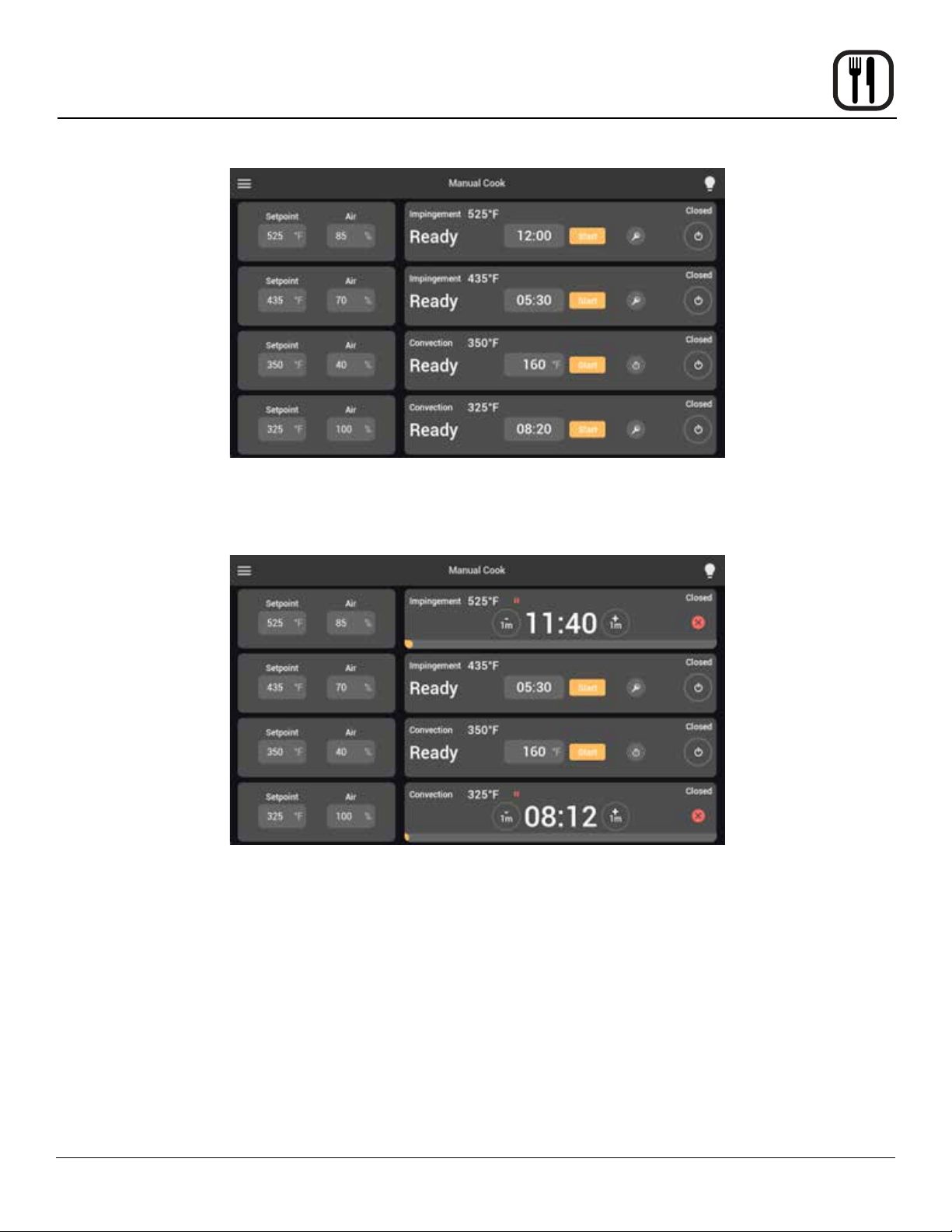
When the chamber(s) have preheated and stablized, you may select the timer eld to
input a time. To use core probe cooking, insert the core probe and select the probe icon
to the right of the start key. This will transition the timer eld to a tempeature. Select the
eld to input a desired temperature target.
Operation
Insert the product in the chosen chamber and select start on the corresponding chamber
to commence the cook.
When the countdown is complete or internal temperature is achieved, an alarm will
sound, the chamber light will begin ashing and the chamber position will show a green
progress bar with a check mark. Selecting the chamber or opening the chamber door will
clear the chamber eld, freeing it for the next cook.
To turn o a chamber, ensure there is no active product in that chamber, and select the
power key to the right side of the chamber eld. The chamber will begin cooling and
automatically shut down once it has achieved a safe temperature.
25
Page 28
Operation
ImVection Touchscreen Control
COOLING DOWN
At any time in Recipe Mode or Manual Mode, you may press the Power icon to the right side of the cooking chamber’s area
on the screen. This forces the oven into a Cool Down mode.
It is VERY important to properly cool the oven down each day to ensure the longevity of the oven and its electrical
components. Failure to do so may result in a decreased lifetime of the oven and its components.
26
Page 29
Operation
ImVection Touchscreen Control
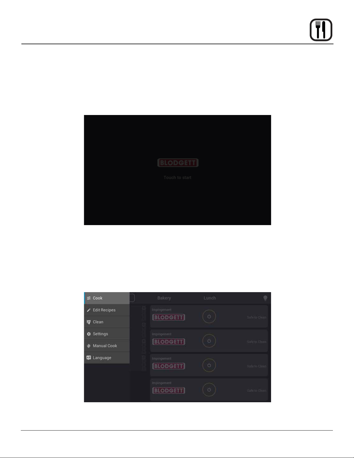
The oven will Cool Down to an ambient temperature and automatically turn o all items. It will nish in a state showing the
touchscreen in the “Sleep” state as shown below.
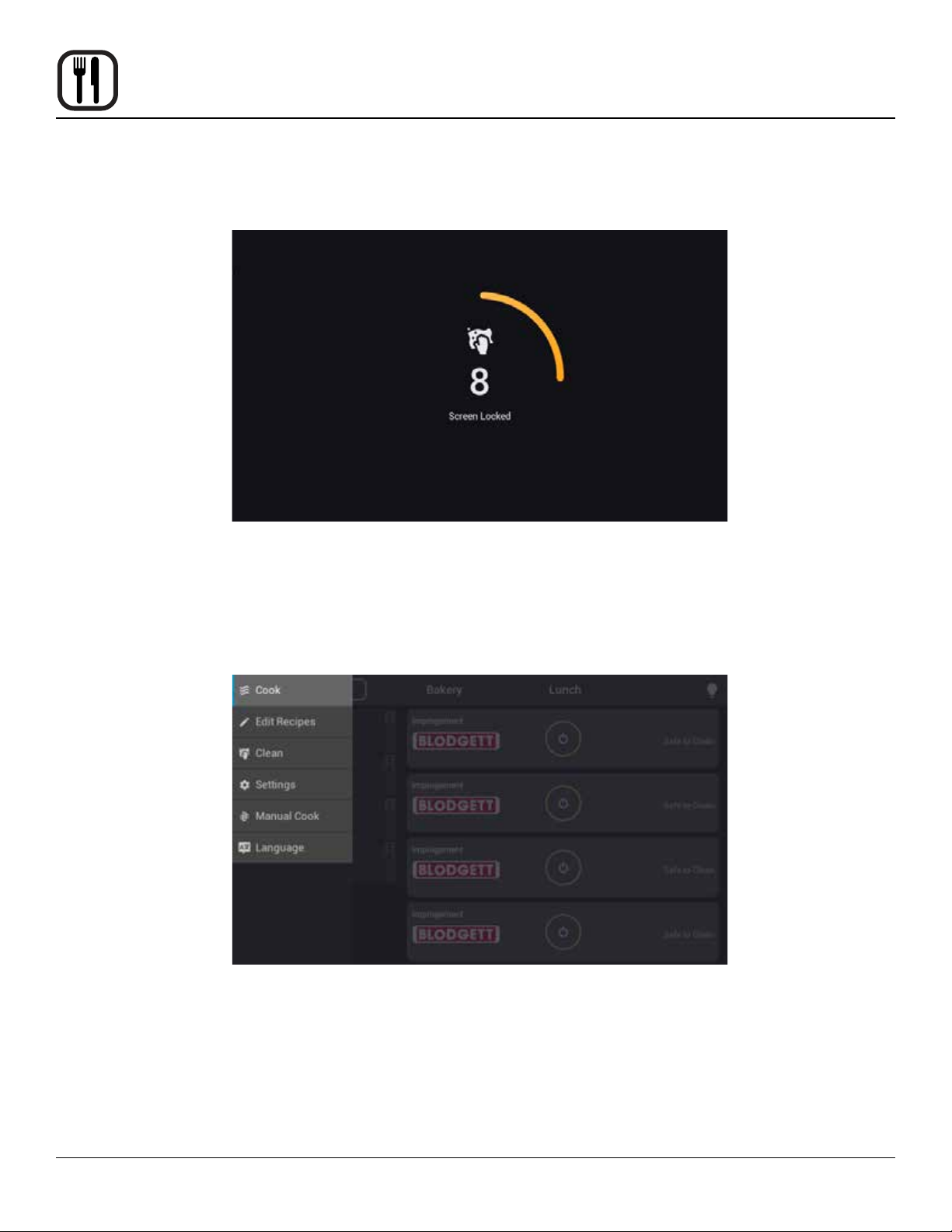
1. To clean the touchscreen, tap on the hamburger icon in the upper left corner of the screen (the 3 lines).
2. Select “Clean”
27
Page 30
Operation
ImVection Touchscreen Control
3. This allows you to wipe the control screen without causing inadvertent inputs. A 10 second countdown will appear on
the screen.
USB FUNCTIONS
Saving Recipies
To save the current recipes and groups featured on the control select the menu icon from the
top left corner of the screen. On the menu that appears select Settings.
28
Page 31
ImVection Touchscreen Control
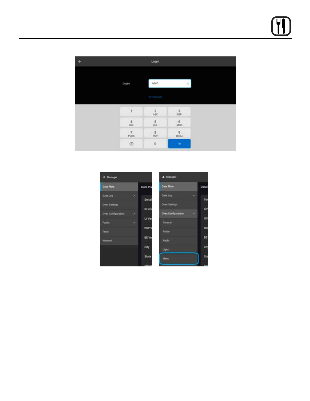
This will prompt you for a passcode. Enter passcode 6647 (MNGR) to enter the Manager
level settings.
Operation
From Manager Settings select Oven Conguration from the left side of the screen, this
will list additional menu options, select Menu.
29
Page 32
Operation
ImVection Touchscreen Control
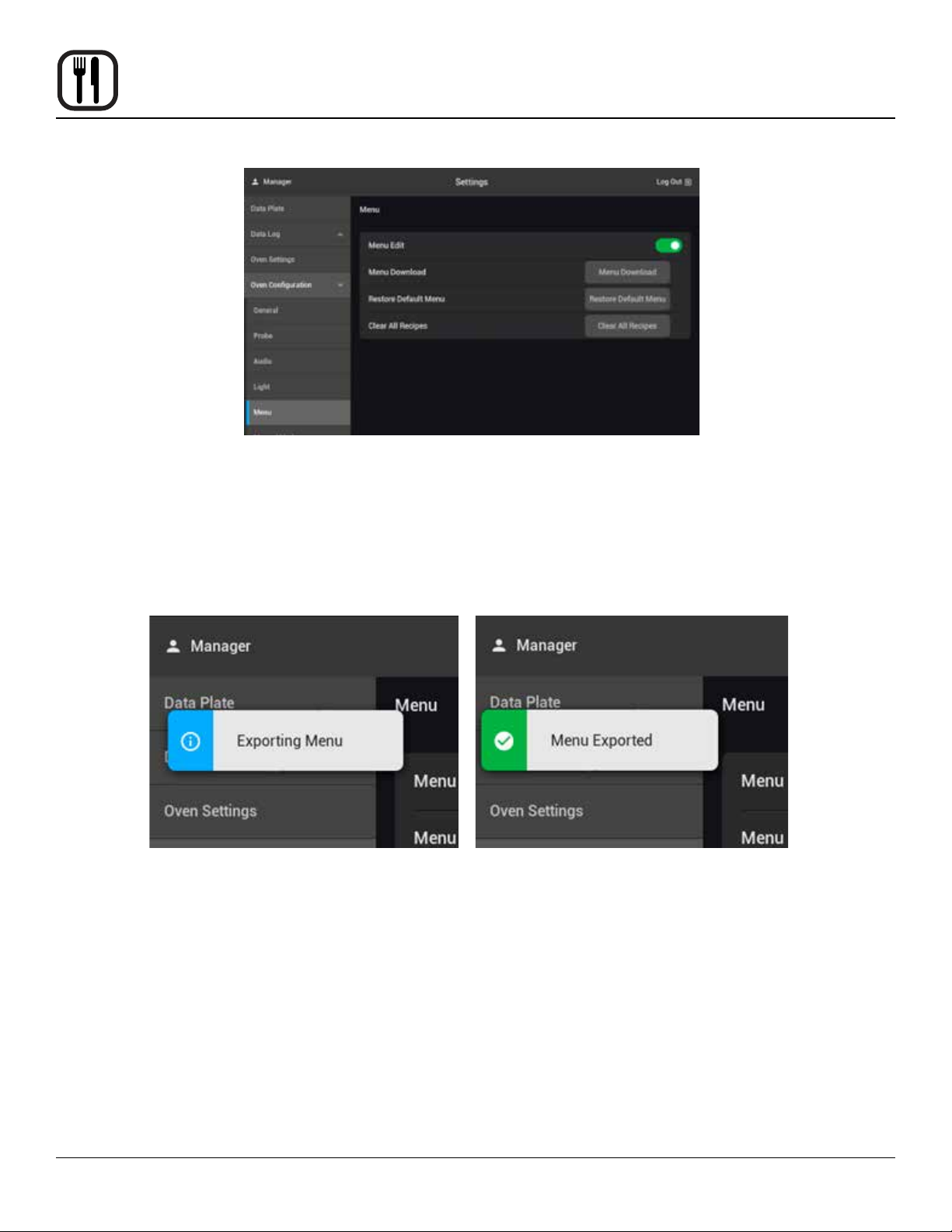
Insert a USB drive into the port at the left side of the control panel, Select Menu Download
to save the current recipe and group settings to the drive.
A notice will appear stating the menu is being exported, and another when the menu has
successfully nished exporting.
30
Page 33
ImVection Touchscreen Control
Loading Menus
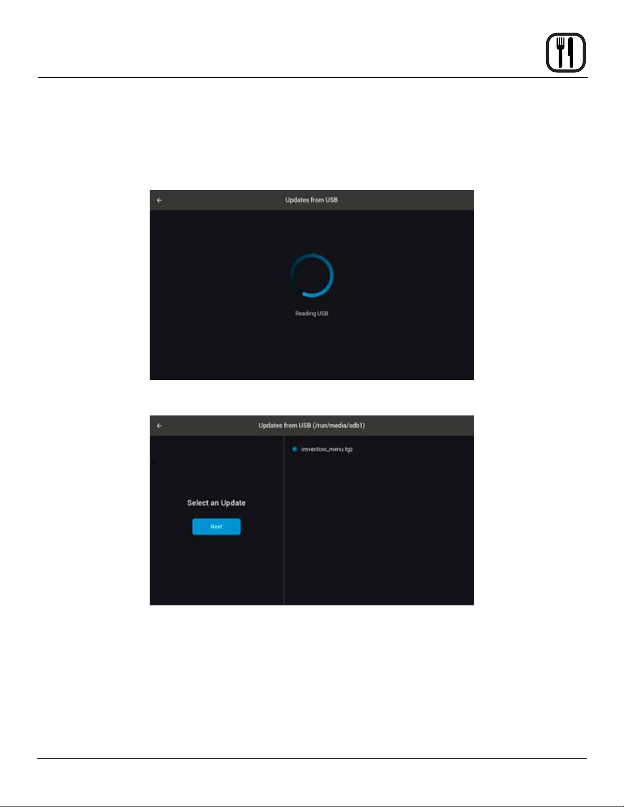
It is recommended that the unit have all chambers o when attempting to upload a menu
le. The control will reboot during the process and any bakes will be canceled. With the
saved menu le on the root of a USB drive (default: imvection_menu.tgz), insert the USB
drive into the port at the left side of the control panel.
Operation
A screen with a progress wheel will appear as the control scans the drive.
When the scan is complete a listing of any available les will be presented for selection.
Select the desired menu le, then press Next.
31
Page 34

Operation
ImVection Touchscreen Control
An additional selection screen will appear displaying the le contents. Check Select All
and press Next.
The control will begin the update process, then reboot. Upon reboot the control will state
that the update has been completed and the new menu will be avliable.
Software Updates (USB)
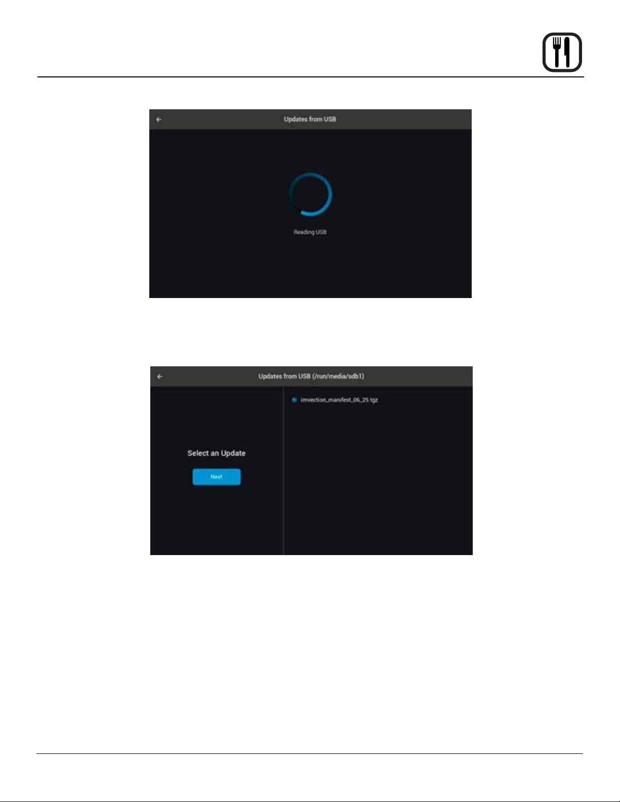
It is recommended that the unit have all chambers o when attempting to update. The
control will reboot during the process and any bakes will be canceled. To apply a software
update to the controler insert the USB drive with the update le into the port at the left
side of the control panel.
32
Page 35
ImVection Touchscreen Control
A screen with a progress wheel will appear as the control scans the drive.
Operation
When the scan is completed, a window will display the avliable les. Select
the manifest le and press Next.
33
Page 36
Operation
ImVection Touchscreen Control
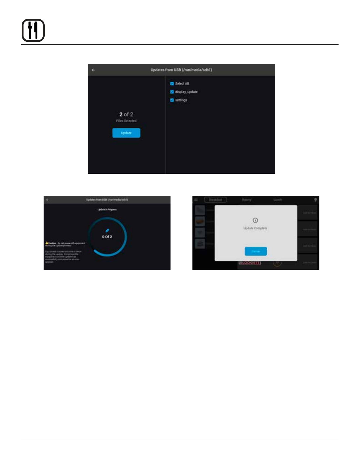
An additional selection screen will appear displaying the le contents. Check Select All
and press Next.
34
Page 37
Cleaning and Preventive Maintenance
Maintenance
WARNING:
Wear proper PPE and adhere to the MSDS
instructions of the oven cleaner.
WARNING:
The oven operates at very high temperatures and retains heat for some time even
after cooling. Take caution that the oven
has properly cooled.
WARNING:
Failure to follow these instructions may
harm the catalytic converter and void your
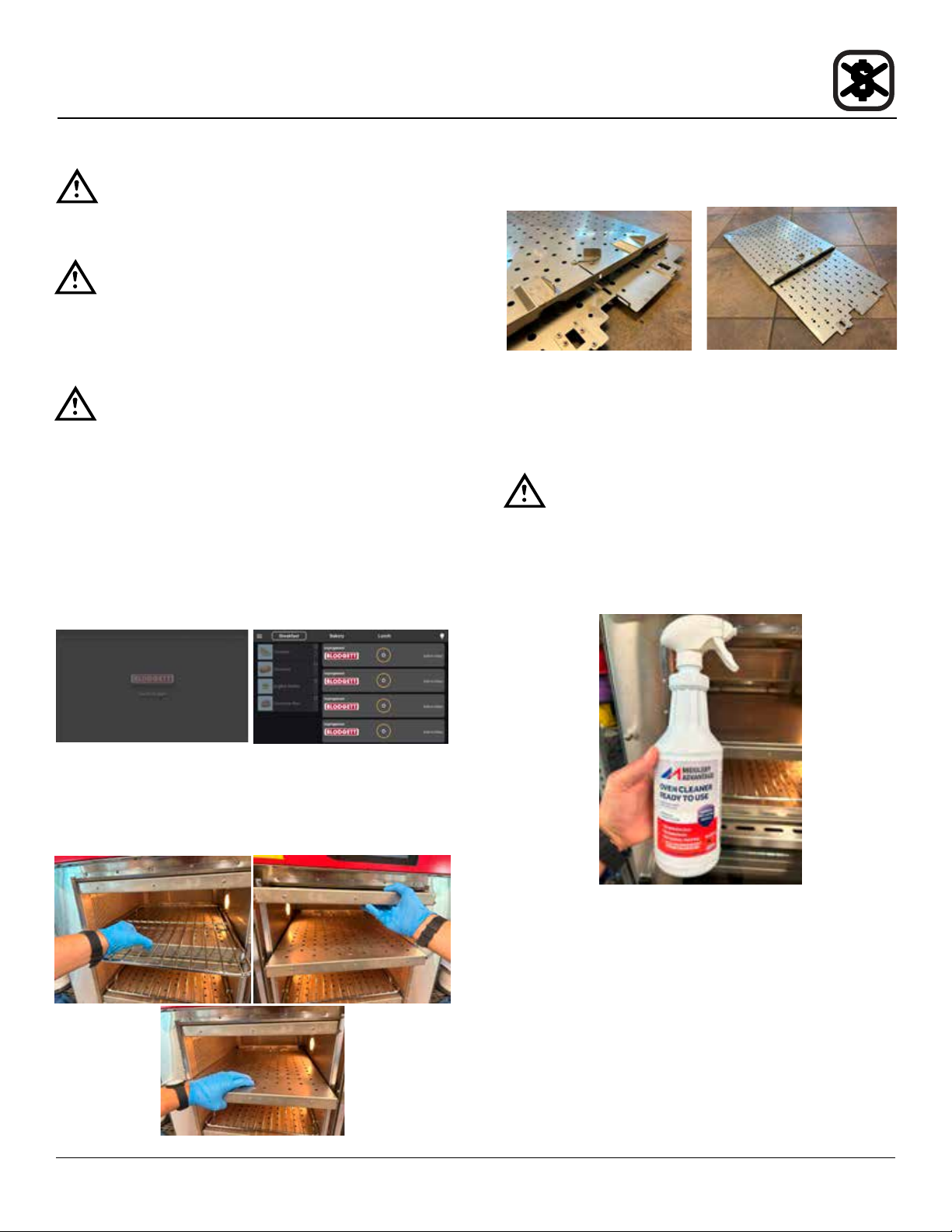
warranty. Do NOT spray any cleaning
agents or water into the small holes that
house the catalytic converter. See images
below in procedure.
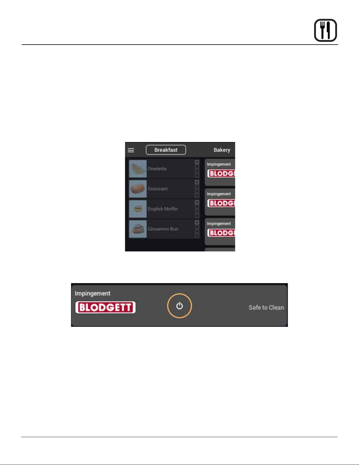
1. Ensure the oven has cooled prior to cleaning. If either
the Blodgett “Start Screen” or the screen stating “Safe to
Clean” is present, the oven has cooled enough to clean.
See images below.
3. The cooking racks and jet plate assemblies may be
cleaned in a Dish Machine or Soaker.
NOTE: If the Dish Machine or Soaker does not remove
all grease of the jet plate assemblies, it is possible
to take the jet plate assemblies apart. Take care of
disassembling and reassemble properly.
CAUTION:
Do NOT spray oven cleaner into the holes on
the left side and rear of the chamber. Do not
spray directly onto the light. Doing so can
damage critical oven components, resulting in
a non-warranty service call.
2. Remove the wire cooking rack from each oven cham-
ber. Remove the jet plate assemblies from each chamber. There is one in the Top and one in the Bottom of
each cooking chamber.
35
Page 38
Maintenance
4. Spray oven cleaner onto the top, bottom, and right side
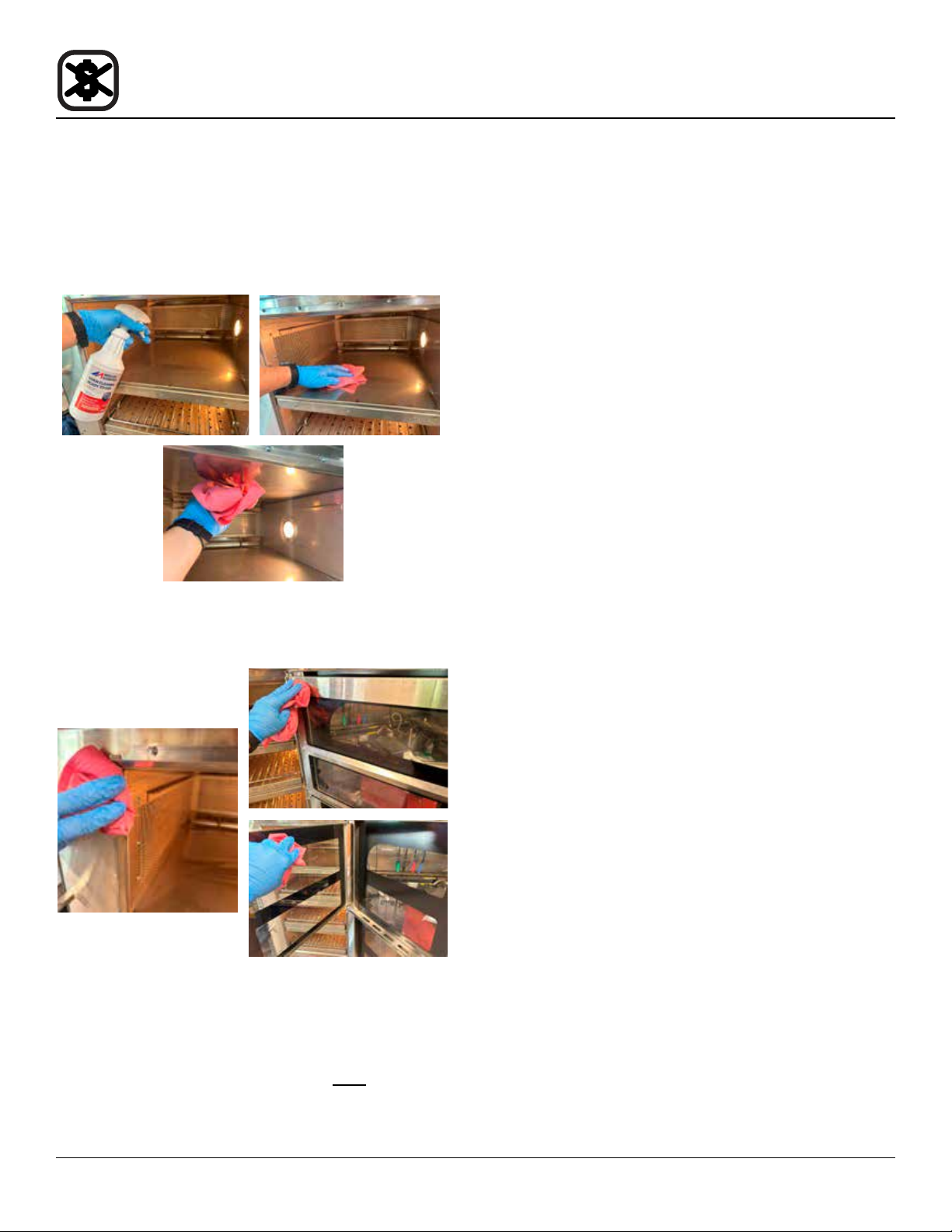
of the chamber. Clean with a non-abrasive scrub pad.
Apply oven cleaner to a clean towel and wipe the left and
rear sides of the chamber. For stubborn stains, spray
Oven Cleaner and allow to soak for 5 minutes. Wipe oven
cleaner from surfaces with a damp towel, then a dry towel.
Cleaning and Preventive Maintenance
5. Wipe the Door Gaskets and Clean the Doors.
6. Reinstall the jet plate assemblies and wire cooking
racks.
7. Clean the Oven Exterior. Wipe the oven exterior with a
clean, damp towel, then a dry towel. Do NOT spray water
or chemicals into the cooling fans on the rear of the oven.
36
 Loading...