

Page 1

BP-50 AND BP-100
PROOFER
INSTALLATION -- OPERATION -- MAINTENANCE
BLODGETT OVEN COMPANY
www.blodgett.com
44 Lakeside Avenue, Burlington, Vermont 05401 USA Telephone (800) 331-5842, (802) 860-3700 Fax: (802)864-0183
PN 23053 Rev D (6/01)
E 2000 --- G.S. Blodgett Corporation
Page 2

IMPORTANT
WARNING: IMPROPER INSTALLATION, ADJUSTMENT,
ALTERATION, SERVICE OR MAINTENANCE CAN CAUSE
PROPERTY DAMAGE, INJURY OR DEATH. READ THE INSTALLATION, OPERATING AND MAINTENANCE INSTRUCTIONS THOROUGHLY BEFORE INSTALLING OR
SERVICING THIS EQUIPM ENT
FORYOURSAFETY
Do not store or use gasoline or other flammable vapors or
liquids in the vicinity of this or any other appliance.
The information contained in this manual is i mportant for the proper
installation, use, and maintenance of this oven. Adhere nce to these
procedures and instructionswill result in satisfactorybaking results
and long, trouble free service. Please read this manual carefully and
retain it for future reference.
Errors: Descriptive, typographic or pictorial errors are subject to correc-
tion. Specifications are subject to change without notice.
Page 3

THE REPUTATION YOU CAN COUNT ON
Forover acentury and a half,The BlodgettOven Companyhas been building
ovensand nothing but ovens. We’veset the industry’s qualitystandard forall
kinds of ovens for every foodservice operation regardless of size, application
or budget. In fact, noone offers more models, sizes, and oven applications
than Blodgett;gas andelectric,full-size, half-size,countertop and deck, convection, Cook’n Hold, Combi-Ovens and the industry’s highest quality Pizza
Oven line. For more information on the fullline of Blodgett ovens contact your
Blodgett representative.
Page 4

Your Service Agency’s Address:
Model:
Serial Number:
Your oven was installed by:
Your oven’s installation was checked by:
Page 5

Table of Contents
Introduction
Proofer Description and Specifications 2..............................
Installation
Delivery and Location 3.............................................
Proofer Assembly 4................................................
Packaging 4....................................................
Caster Assembly 4..............................................
Leg Attachment 4...............................................
Double Section Assembly 5......................................
Utility Connections --- Standards and Codes 6.........................
Electrical Connection and Initial Startup 7.............................
Operation
Safety Information 8................................................
Electro-Mechanical Thermostat and Humidity Controller 9...............
Solid State with Infinite Setting & Electro-Mechanical Humidity Controller 10
Solid State with Infinite Setting & Solid State Humidity Controller 11.......
Maintenance
Cleaning and Preventative Maintenance 12.............................
Page 6
Introduction
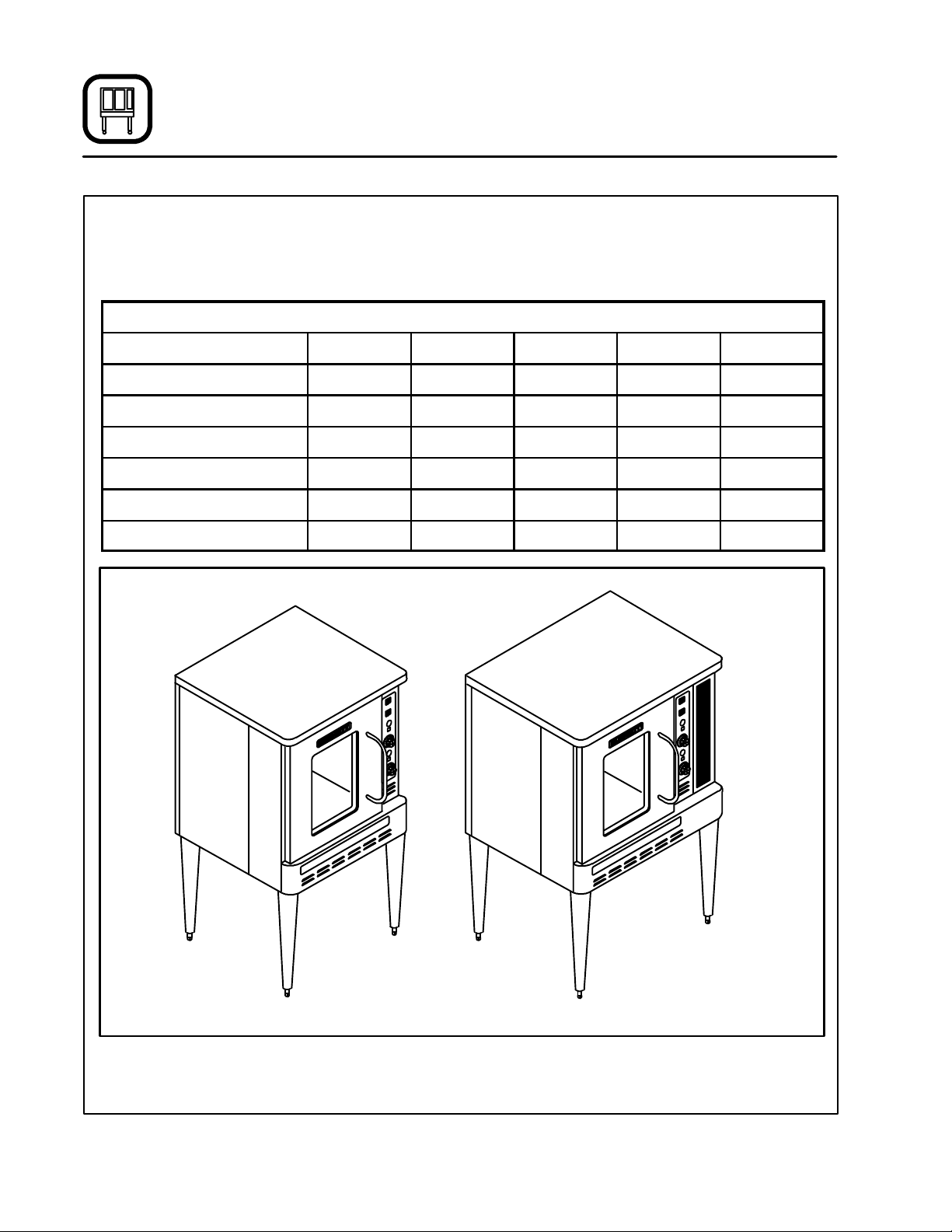
Proofer Description and Specifications
The B P Series proofers are available in two (2)
sizes. The BP-50 models are designed to fit under
theBlodgettlineof half sizeconvection ovens. The
ELECTRICAL SPECIFICATIONS (per section)
Model Watts Hz Volts Phase Amps
BP-50 1425 60 120 1 11.9
BP-50 1425 50 220 1 6.5
BP-50 1425 50 240 1 5.9
BP-100 1675 60 120 1 14.0
BP-100 1675 50 220 1 7.6
BP-100 1675 50 240 1 7.0
BP-100 models are designed to fit under the
Blodgett line of full size convection ovens.
BP-50 PROOFER BP-100 PROOFER
Figure 1
2
Page 7

Installation
Delivery and Location
DELIVERY AND INSPECTION
All Blodgett proofers are shipped in containers to
prevent damage. Upon delivery ofyournewproofer:
D
Inspecttheshippingcontainerforexternaldamage. Any evidenceof damage should be noted
onthe deliveryreceipt which mustbe signed by
the driver.
D
Uncratethe prooferand check for internaldamage. Carriers will accept claims for concealed
damage if notified within fifteendays of delivery
and the shipping container is retained for inspection.
The Blodgett Oven Company cannot assume
responsibility for loss or da m age suffered in
transit. The carrier assumed full responsibility
for delivery in good order when the shipment
was accepted. We are, however, prepared to
assist you if filing a claim is necessary.
PROOFER LOCATION
The well planned and proper placement of your
proofer will result in long term operator convenience and satisfactory performance.
D
Placethe proofer inan area whichis accessible
forproperoperationandservicing.
D
DO NOT place the proofer on a curb base or
seal to a wall. Either condition will restrict the
proper flow of ventilation air , resulting in damage to the unit.
3
Page 8

Installation
Proofer Assembly
PACKAGING
Before beginning assembly of the proofer, verify
that all the components necessary for the correct
configuration have been received. In addition to
the proofer other accessories may be required.
Single Sections:
The 25” (63.5 cm) legs and the optional regular
casters are packaged in the proofer cabinet.
Double Sections:
Thelowprofilecastersarepackagedinthelower
proofer section.
Accessories:
Proofer racks, rack guides and guide stops a re
packaged within the proofer cabinet.
CASTER ASSEMBLY
NOTE: Install the locking casters on the front of
theproofer. Install the non-locking casters
on the back of the proofer.
NOTE: If your proofer does not include casters,
proceed to the leg attachment section on
page 4.
Casters with 25” (63.5 cm) Legs
1. Insert the stem of a caster into the 1-1/2” I.D.
leg tubing. The caster shouldfit snugly. If not,
removethe castera ssembly and adjust as follows:
Hold the large hex nut. Tighten the knurled
washerto expandtherubber sleevea nd allow
the caster assembly to fit snugly into the leg
tubing. Make sure the caster fits completely
inside the leg tubing.
2. Tightenthe largehexnutas muchas possible.
This will further expand the rubber sleeve
against the leg tubing wall. If the rubber
sleeves turn inside the leg tubing, removethe
caster and repeat the caster adjustment procedure in 1.
Low Profile Casters
1. Carefully tip the proofer on it’s side.
2. Align the low profilecasters with the boltholes
in the corners on the bottom of the proofer.
3. Securethe casterstotheprooferwiththebolts
provided.
Figure 2
Figure 3
25” (63.5 CM) LEG ATTACHMENT
NOTE: If casters are used, remember to install the
legs with the locking casters in the front of
the proofer. Thenon-lo c kingcasters should
beinstalledonthe rearlegs. Besure thatthe
locksaresetonthefrontcasters.
1. Raisethe prooferatleast 30” (76 cm)off ofthe
ground using a lift.
2. Alignthe threaded studs of the front legs with
the bolt holes located in the corners of the
proofer’s bottom.
3. Turn the legs clockwise and tighten to the
nearest full turn.
4. Align the leg plate holes with the remaining
bolt holes. Secure the legs with the four (4)
1/2” x 3/4” bolts provided.
4
Page 9

Installation
Proofer Assembly
NOTE: If casters are used, ensure that the
locks are set on the casters.
Repeat Steps 1---4 for the rear legs.
The proofer should be leveled after being moved
to the operating location. Except for units with
casters, level the proofer by screwing the adjustable feet in or out as necessary.
Half Size Convection Oven on a BP-50
NOTE: The following instructions are for half size
convection ovens with LH doors.
1. On gas ovens, remove the combustion
compartment cover. On electric ovens, open
the control compartment cover.
2. Remove the access panel from the oven.
3. Remove the rear panel from the proofer.
4. Remove the control cover from the proofer .
5. Locate and align the front and rear bolt holes
with the bolt holes in the proofer frame.
6. Place a round washer and a hex nut on the
bottomendof eachbolt.Tightensecurelywith
a wrench.
7. Replace the combustion cover or close the
control compartment cover on the oven.
8. Replace the access panel on the oven.
9. Replace the rear panel on the proofer.
10. Replace the control cover on the proofer.
The proofer should be leveled after being as-
sembledand moved to theoperating location.Except for units with casters, adjust the feet located
on the bottom of each leg to level the unit.
Figure 4
DOUBLE SECTION ASSEMBLY
Full Size Convection Oven on a BP-100
1. Securethe lowprofilecastersto theprooferas
described.
2. Place the oven section on top of the proofer
section.
3. Remove the rear panel from the proofer.
4. Alignthe two rear bolt holes oftheproofersectionwith the two threaded holes in the bottom
of the oven section.
5. Insert a bolt from the bottom up through each
of the two holes and tighten securely.
6. Reinstall the rear panel on the proofer.
DOUBLE SECTION ASSEMBLY
(BP-100shown with panels removed for clarity)
Figure 5
5
Page 10

Installation
Utility Connections --- Standards and Codes
THE INSTALLATION INSTRUCTIONS CONTAINED HEREIN ARE FOR THE USE OF QUALIFIEDINSTALLATIONAND SERVICEPERSONNEL
ONLY. INSTALLATION OR SERVICE BY OTHER
THAN QUALIFIED PERSONNEL MAY RESULT IN
DAMAGE TO THE proofer AND/OR INJURY TO
THE OPERATOR.
Qualified installation personnel are individuals, a
firm, a corporation, or a company which either in
person or through a representative are engaged
in, and responsible for:
D
the installationofelectrical wiring from the electric meter, main control box or service outlet to
the electric appliance.
Qualified installation personnel must be experienced in such work, familiar with all precautions
required,and havecompliedwith allrequirements
of state or local authorities having jurisdiction.
U.S. and Canadian installations
All proofers, when installed, must be electrically
groundedinaccordancewith localcodes,orinthe
absenceoflocalcodes, withtheNationalElectrical
Code, ANSI/NFPA70---Latest Edition and/or Canadian National Electric Code C22.2 as applicable.
General export installations
Installationmust conform with Local and National
installation standards. Local installation codes
and/or requirements may vary. If you have any
questionsregarding the proper installationand/or
operation of your Blodgett proofer, please contact
yourlocaldistributor. If youdonot have alocaldistributor,please calltheBlodgettOven Companyat
0011-802-860-3700.
6
Page 11

Installation
Electrical Connection and Initial Startup
ELECTRICAL CONNECTION
This appliance is rated UL and CSA approved for
operation on 120VAC, 60 Hz, single phase,
grounded circuits, International 220 and 240VAC,
50 Hz versions are also available. Before making
anyconnection to this appliance, check the rating
plate attached to the underside of the front top
trim, directly above the control panel.
NOTE: Be sure that the proofer is connected to
the proper electrical supply.
The supply cord is connected to the junction box
in the rear of the proofer.
Wiring diagrams are located on the inside of the
control compartment, as well as the rear of the
proofer.
WARNING!!
Always disconnect the power supply to
theappliancebeforeservicingtheunit.
NOTE: There is no power to the heating element
without the rear blower operating. This is
to prevent damage to the element.
INITIAL STARTUP
Each proofer, and its component parts, have
been thoroughly tested and inspected prior to
shipment.However,it is often necessary to further test or adjust the proofer as part of a normaland proper installa tion. Theseadjustments
are the responsibility of the installer, or dealer.
Since these adjustments are not considered
defects in material or workmanship, they are
notcovered by the Original Equipment Warranty.Theyinclude,butarenotlimitedto:
DDDD
calibration of the thermostat
DDDD
adjustment of the doors
DDDD
leveling
DDDD
tightening of fasteners.
No installationshouldbe consideredcomplete
without proper inspection, and if necessary,
adjustment by qualified installation or service
personnel.
The following is a check-listto be completed by
qualified personnel prior to turning on the
applianceforthefirsttime.
j
Verify that the proofer has been properly
installed with the preceding installation instructions. If so, proceed to the operation
instructions. Allow the proofer to operate
forabouttwo (2) hoursprior tousing for the
first time.
7
Page 12

Operation
Safety Information
THE INFORMATION CONTAINED IN THIS SECTIONISPROVIDEDFORTHEUSE OFQUALIFIED
OPERATINGPERSONNEL. QUALIFIED OPERATING PERSONNEL ARE THOSE WHO HAVE
CAREFULLY READ THE INFORMATION CONTAINED IN THIS MANUAL, ARE FAMILIAR WITH
THE FUNCTIONS OF THE OVEN AND/OR HAVE
HAD PREVIOUS EXPERIENCE WITH THE OPERATIONOFTHE EQUIPMENTDESCRIBED.ADHERENCE TO THE PROCEDURES RECOMMENDED HEREIN WILL ASSURE THE
ACHIEVEMENT OF OPTIMUM PERFORMANCE
AND LONG, TROUBLE-FREE SERVICE.
Please take the time to read the following safety
andoperatinginstructions. Theyare the keyto the
successful operation of your Blodgett conveyor
oven.
SAFETY TIPS
For your safety read before operating
General safety tips:
D
DONOT remove the control panel coverunless
the oven is unplugged.
8
Page 13

Operation
Electro-Mechanical Thermostat and Humidity Controller
COMPONENT DESCRIPTION
1. POWER SWITCH --- controls power to the
proofer for ON/OFF operation.
ON
1
OFF
2
LOW WATER
3
TEMPERATURE
OFF
4
5
HUMIDITY
OFF
LOW
HIGH
2. LOWWATERINDICATORLIGHT --- whenlitindicates need to add water.
3. AIR HEATER PI LOT LIGHT --- wh en lit, indicates air heater ON operation.
4. THERMOSTAT --- allows for temperature
selection from 60-125_F(16-52_C).
5. WATER HEATER PILOT LIGHT --- when lit, indicates water heater ON operation.
6. HUMIDITY CONTROLLER --- allows humidity
selection from LOW to HIGH.
CONTROL OPERATION
1. Visually check the level in the water pan. Add
water as necessary.DO NOT overfill the res-
ervoir.
NOTE: The water level monitoring system will
sound a buzzer, located behind the
control panel, and illuminate a front
panel indicator light when the water
falls below the factory set level. Add
three (3) quarts (96 fl. oz.) of water to
restore the fluid to the correct level.
2. Set the THERMOSTAT (4) to the desired temperature.
3. Set the HUMIDITY CONTROLLER (6) to the
desired humidity level.
4. Set the POWER SWITCH (1) to the ON position. Allow the cavity temperature and humiditytoreach the correct levelbeforeloadingthe
product.
5. Remove the product when ready.
6. Toggle the POWER SWITCH (1) to OFF.
6
Figure 6
9
Page 14

Operation
Solid State with Infinite Setting & Electro-Mechanical Humidity Controller
CONTROLS
1. POWER SWITCH --- controls power to the
proofer for ON/OFF operation.
ON
1
OFF
2
LOW WATER
3
TEMPERATURE
4
5
HUMIDITY
OFF
LOW
HIGH
2. LOWWATERINDICATORLIGHT --- whenlitindicates need to add water.
3. AIR HEATER PI LOT LIGHT --- wh en lit, indicates air heater ON operation.
4. SOLID STATE TEMPERATURE CONTROLLER
--- allows an infinite number of temperature
settings from 80-125_F(27-52_C).
5. WATER HEATER PILOT LIGHT --- when lit, indicates water heater ON operation.
6. HUMIDITY CONTROLLER --- allows humidity
selection from LOW to HIGH.
OPERATION
1. Visually check the level in the water pan. Add
water as necessary.DO NOT overfill the res-
ervoir.
NOTE: The water level monitoring system will
sound a buzzer, located behind the
control panel, and illuminate a front
panel indicator light when the water
falls below the factory set level. Add
three (3) quarts (96 fl. oz.) of water to
restore the fluid to the correct level.
2. Set the SOLID STATE TEMPERATURE CONTROLLER (4) to the desired temperature.
3. Set the HUMIDITY CONTROLLER (6) to the
desired humidity level.
4. Set t he POWER SWITCH (1) to ON and allow
the cavity temperature and humidity to reach
the correct level before loading the product.
5. Remove the product when ready.
6. Toggle the POWER SWITCH (1) to OFF.
6
Figure 7
10
Page 15

Operation
Solid State with Infinite Setting & Solid State Humidity Controller
CONTROLS
1. POWER SWITCH --- controls power to the
proofer for ON/OFF operation.
ON
1
OFF
2
LOW WATER
2. LOWWATERINDICATORLIGHT --- whenlitin-
dicates need to add water.
3. AIR HEATER PI LOT LIGHT --- wh en lit, indi-
cates air heater ON operation.
4. SOLID STATE TEMPERATURE CONTROLLER
--- allows an infinite number of temperature
settings from 80---125_F (27---52_C).
5. WATER HEATER PILOT LIGHT --- when lit, in-
dicates water heater ON operation.
6. SOLID STATEHUMIDITYCONTROLLER --- Al-
lows an infiniteselection of humidity levels between 70% and 99% RH. (relative humidity).
3
TEMPERATURE
1. Visually check the level in the water pan. Add
water as necessary.DO NOT overfill the res-
ervoir.
NOTE: The water level monitoring system will
sound a buzzer, located behind the
control panel, and illuminate a front
panel indicator light when the water
OPERATION
4
falls below the factory set level. Add
three (3) quarts (96 fl. oz.) of water to
restore the fluid to the correct level.
2. Set the SOLID STATE TEMPERATURE CON-
TROLLER (4) to the desired temperature.
3. Set the SOLID STATE HUMIDITY CONTROL-
5
HUMIDITY
LER (6) to the desired humidity level.
4. Set t he POWER SWITCH (1) to ON and allow
the cavity temperature and humidity to reach
thecorrectlevelbeforeloadingtheproduct.
5. Remove the product when ready.
6. Toggle the POWER SWITCH (1) to OFF.
6
%R.H.
Figure 8
11
Page 16

Maintenance
Cleaning and Preventative Maintenance
CLEANING THE PROOFER
Painted and stainless steel proofers may be kept
clean and in good condition with a light oil. Saturate a cloth, and wipe the proofer when it is cold.
Dry the unit with a clean cloth. On the stainless
front or interiors, heat tint and heavy discoloration
or deposits of baked on splatter may be removed
with a good non-toxic industrial stainless steel
cleaner. Apply cleaners when the proofer is cold,
and always rub with the grain of the metal.
WARNING!!
Disconnect the unit from power supply
before servicing or cleaning.
PERIODIC CLEANING
Daily:
Clean residue from the unit with a small brush.
Weekly:
Brush out control area.
Every 6 Months:
Clean the ductwork system and water pan.
CLEANING THE DUCTWORK SYSTEM
1. Disconnect the power supply to the proofer.
2. Movethe unittoallowaccesstotheremovable
rear panel. Lift the panel up and pull the bottom out. Carefully lower the panel while pulling the line cord through the access hole.
3. Slide the rear duct up to disengage the duct
flanges from the offset guide track. Remove
the duct. Set it on the left side of the unit.
NOTE: Be careful not to damage the control
wires or the capillary tube.
4. Slide the top duct straight out of the track
through the rear of the unit.
5. Remove the two quick-disconnect plugs.
Slideoutthelowerductassembly.DONOT
damage the blower wheel or heating elements. The water pan assembly may be removedfromtheductforeasiercleaning.
6. Replace by reversing Steps 1---5 above. Be
sure to make proper electrical connections.
CLEANING THE WATER PAN
Visuallyinspectthew a ter panfor residualbuildup.
The water pan alone can be removed through the
front of the unit.
1. Disconnect the power supply to the proofer.
2. Removethet humbscrews fromthe lowercover. Grasp the cover by the sides. Pull out and
up toclear the three holding tabs mountedon
the inside bottom of the cover.
3. Remove the quick-disconnect plug from the
front of the water pan.
4. Pullup on the water pan todisengage thetab
from the front slot. Pull the pan forward.
NOTE: If the pan contains water , be careful
not to spill any inside of the unit.
5. Remove the pan from the proofer and clean
thoroughly .DO NOT immersethe pan inwa-
ter.
6. Replace by reversing Steps 1---5 above. Be
sure to line up the holes on the trim piece below the door with the lower cover. Lock the
tabs on the bottom inside of the cover.
OnBP-50unitsbe sure to insert the tab on the
right side of the lower cover into the slot in the
control panel cover.
7. Install the thumbscrews. Be sure to position
thelowertrimpiece underneaththe lowercover.Makesurethesealbetweenthedoorgasket and the lower door trim is tight.
PREVENTATIVE MAINTENANCE
The best preventativemaintenance measuresare
theproper installationof the equipmentand a program for routinely cleaning the proofer.
Every 6 Months:
Thefanassembly blower motor,located inthelower air duct assembly at the rear of the unit, should
beoiledwithanSAE20weightoil.
1. Disconnect the power supply to the unit. Applythe oiltothe twofillertubes locatedateach
end of the motor shaft.
The rest of the proofer needs no lubrication. If
maintenance or repairs are required, they
should be performed by qualified personnel
only.
12
Page 17

CUSTOMER
INSERT
WIRING DIAGRAM
HERE
 Loading...