

Page 1

BC14E, BC14G,
BC14EDS, BC14GDS and B14G
COMBINATION OVEN STEAMER
INSTALLATION -- OPERATION -- MAINTENANCE
BC14E, BC14G,
BC14EDS, BC14GDS et B14G
COMBI-FOUR/ÉTUVE À VAPEUR
MANUEL D’INSTALLATION -- FONCTIONNEMENT -- ENTRETIEN
BLODGETT COMBI
www.blodgett.com
44 Lakeside Avenue, Burlington, Vermont 05401 USA Telephone (800) 331-5842, (802) 860-3700 Fax: (802)864-0183
P N R 10382 R e v E (5/ 06)
E 2003 --- Blodgett Combi
Page 2

A PERSONAL WORD FROM BLODGETT COMBI
QUELQUES MOTS DE BLODGETT COMBI
Congratulations on your purchase of a BLODGETT Combi appliance. We
firmly believe that your choice has been a wise one, and trust you will receive many years of excellent service from your new Combi.
You will find that cooking with Combi appliances saves time, labor and
extensive cleaning of both the kitchen and the unit.
With Combi appliances the quality, taste, consistency, and look of your
food are improved, thus endorsing the policy to which we’ve always adhered: “For Better Cooking!”
Once you’ve had a chance to use your Combi, please tell us, your dealer
and colleagues about any creative and interesting applications you have
discovered; exchange ideas with other users. Be sure to advise us or
your dealer immediately should any mechanical or technical problems
be encountered (...we’re here to help!) and above all “Enjoy Cooking the
BLODGETT Combi Way!
For information on cooking, please refer to our separate cooking guide.
Toutes nos félicitations sur votre achat d’appareil de Blodgett Combi.
Nous croyons fermement que votre choix est un choix raisonnable et
nous sommes certains que vous obtiendrez de nombreuses années
d’excellent service de votre nouveau four multi-usages.
Vous allez découvrir que la cuisson dans les appareils Combi économise
le temps, le travail et le degré de nettoyage de l’appareil aussi bien que
de la cuisine.
Avec les appareil de Combi, la qualité, le goût, la consistence et l’apparence des aliments sont améliorés, s’accordant, de ce fait, avec notre
politique ”Pour une meilleure cuisson !”
Une fois que vous aurez eu la chance d’utiliser notre Combi, informez
nous, votre concessionnaire et vos collègues, de toutes les applications
nouvelles et intéressantes que vous avez découvertes ; échangez vos
idées avec d’autres utilisateurs. N’hésitez pas à nous prévenir, ou votre
concessionnaire, de tout problème mécanique ou technique que vous
pourriez rencontrer (... nous sommes ici pour vous aider) et par-dessus
tout “Régalez-vous à cuisiner à la façon BLODGETT Combi!
Pour obtenir de plus amples informations sur l’art culinaire, veuillez consulter notre livre de cuisine séparé.
Page 3

IMPORTANT
WARNING: IMPROPER INSTALLATION, ADJUSTMENT, ALTERATION, SERVICE OR
MAINTENANCE CAN CAUSE PROPERTY DAMAGE, INJURY OR DEATH. READ THE
INSTALLATION, OPERATING AND MAINTENANCE INSTRUCTIONS THOROUGHLY
BEFORE INSTALLING OR SERVICING THIS EQUIPMENT
AVERTISSEMENT: UNE INSTALLATION, UN AJUSTEMENT, UNE ALTÉRATION, UN
SERVICE OU UN ENTRETIEN NON CONFORME AUX NORMESPEUT CAUSER DES
DOMMAGESÀ LA PROPRIÉTE,DES BLESSURESOU LA MORT.LISEZ ATTENTIVEMENT LES DIRECTIVES D’INSTALLATION, D’OPÉRATION ET D’ENTRETIEN AVANT
DE FAIRE L’INSTALLATION OU L’ENTRETIEN DE CET ÉQUIPEMENT.
INSTRUCTIONS TO BE FOLLOWED IN THE EVENT THE USER SMELLS GAS
MUST BE POSTED IN A PROMINENT LOCATION. THIS INFORMATION MAY BE
OBTAINED BY CONTACTING YOUR LOCAL GAS SUPPLIER.
LES INSTRUCTIONS À RESPECTER AU CAS OÙ L’UTILISATEUR PERÇOIT UNE
ODEUR DE GAZ DOIVENT ÊTRE AFFICHÉES DANS UN ENDROIT BIEN VISIBLE.
VOUS POUVEZ VOUS LES PROCURER AUPRÈS DE VOTRE FOURNISSEUR DE
GAZ LOCAL.
FORYOURSAFETY
Do not store or use gasoline or other flammable vapors or liquids in the vicinity
of this or any other appliance.
AVERTISSEMENT
Ne pas entreposer ni utiliser de l’essence ni d’autres vapeurs ou liquides inflammables dans le voisinage de cet appariel, ni de tout autre appareil.
The information contained in this manual is important for the proper installation,
use, and maintenance of this oven. Adherence to these procedures and instructions will result in satisfactory baking results and long, trouble free service.
Please read this manual carefully and retain it for future reference.
Les informations données dans le présent manuel sont importantes pour installer,
utiliser et entretenir correctement ce four. Le respect de ces instructions et procédures permettra d’obtenir de bonsrésultats de cuisson et une longue durée de service sans problèmes. Veuillez lire le présent manuel et le conserver pour pouvoir
vous y reporter à l’avenir.
Errors: Descriptive, typographic or pictorial errors are subject to correction. Specifica-
tions are subject to change without notice.
Erreurs:Les erreurs de description, de typographie ou d’illustration font l’objet de
corrections. Les caractéristiques sont sujettes à modifications sans préavis.
Page 4

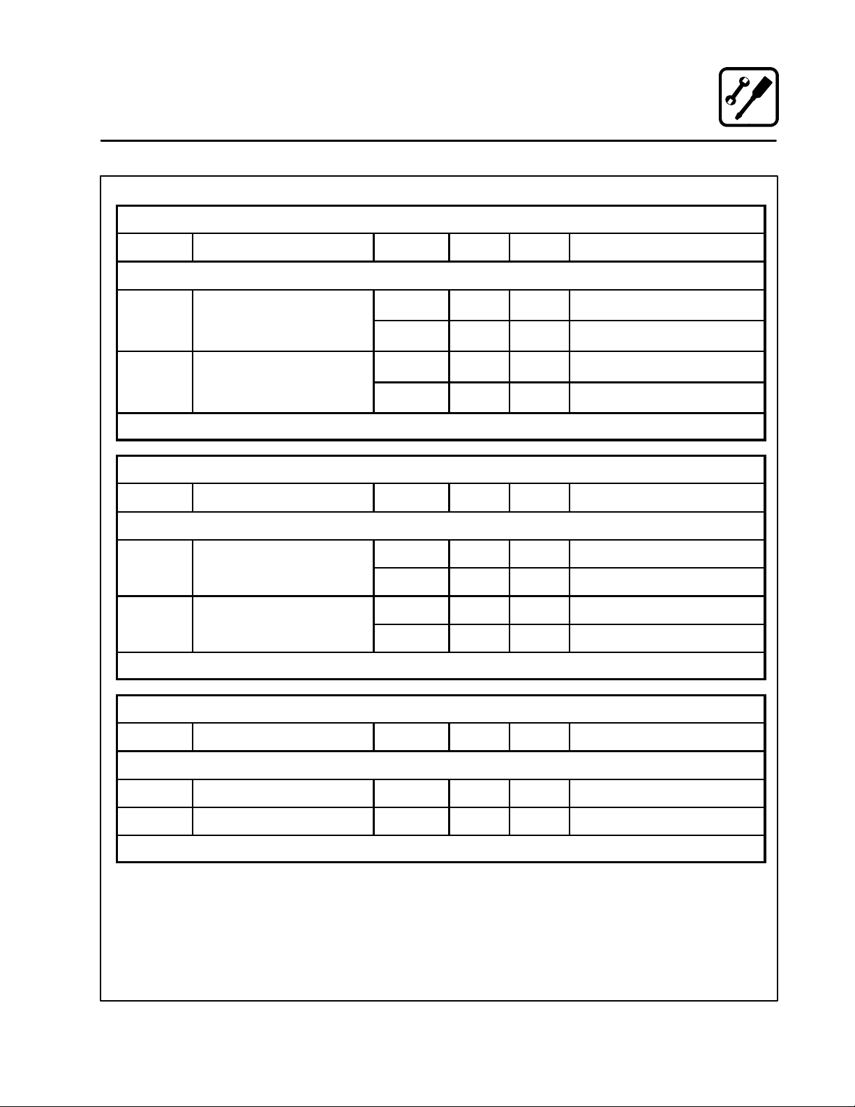
Your Service Agency’s Address:
Adressedevotreagencedeservice:
Model/Modèl:
Serial Number/Numéro de série:
Your appliance was installed by/
Installateur de votre four:
Your oven’s installation was checked by/
Contrôleur de l’installation de votre four:
Page 5

Table of Contents/Table des Matières
Introduction
The Blodgett Combi-Oven/Steamer 2.....
Description of the Combi-Oven/Steamer 3.
Oven Features 4.......................
Installation
Agency Approvals 5....................
Owner’s Responsibilities 6...............
Oven Location and Ventilation 9..........
Leg Attachment 10......................
Caster Attachment 11....................
Stacking 12.............................
Oven Leveling and Steam Connection 13...
Plumbing Connections 14................
Electrical Connections 15................
Gas Connections 16.....................
Gas Hose Restraint 18...................
Adjustments 19.........................
Final Check Lists 20.....................
Operation
Safety Information for Gas Units 22........
Gas Controls 23.........................
Standard Controls 24....................
Optional Cook & Hold 26.................
Optional Meat Probe 30..................
Maintenance
Spray Bottle Operating Procedure 31......
Cleaning and Preventive Maintenance 32...
Deliming 34.............................
Communication 41......................
Introduction
Le four-étuveur Combi de Blodgett 44......
Descriptiondufour-étuveurCombi 45......
Fonctionnalités du four 46................
Installation
Certifications 47.........................
Responsabilités du propriétaire 48.........
Emplacement du four et mise de niveau et
Ventilation 51...........................
Montage des pieds 52...................
Accessoire des roulettes 53..............
Superposition 54........................
Mise de niveau du four et branchement
del la vapeur 55.........................
Raccordement de la plomberie 56.........
Raccordement à l’électricité 57............
Raccordement au gaz 58.................
Câble d’immobilisation du tuyau à gaz 60..
Ajustements 61.........................
Liste de vérification finale 62..............
Fonctionnement
Renseignements sur la sécurité des
appareils au gaz 64......................
Commandes du gaz 65..................
Commandes standard 66................
Cuisson et Pause en Option 68...........
Sonde thermique optionnelle 73...........
Entretien
Procédure de fonctionnement du
pulvérisateur 74.........................
Nettoyage et entretien préventif 75........
Détartrage 77...........................
Communications 84.....................
Page 6
Introduction
The Blodgett Combi-Oven/Steamer
The Blodgett Combi-Oven/Steamer offers a completely new method of cooking. With the Oven/
Steamer you have the choice of two cooking pro-
cesses: Steam and Hot Air, either...
D Separately
D Combined, or
D In Sequence
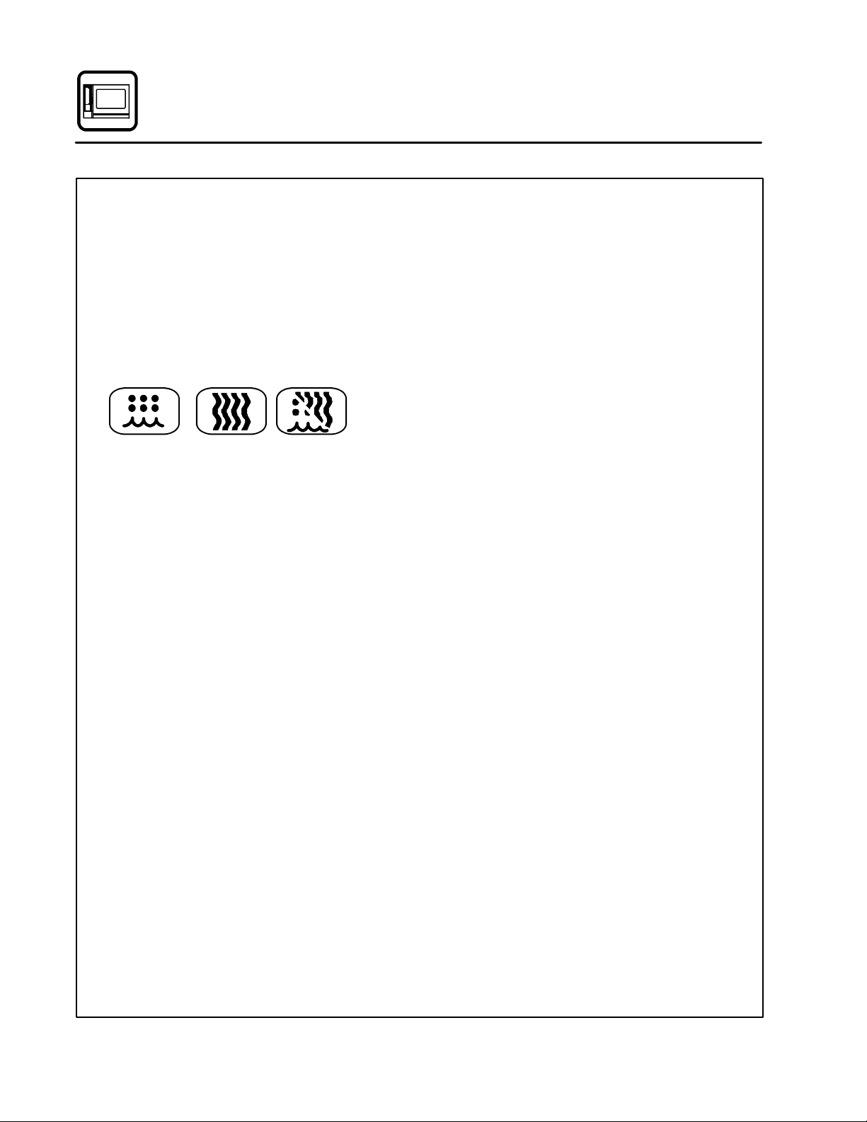
And for easy operation you can choose from three
modes:
Steam Hot Air
Combi
Steam &
Hot Air
In the Steam mode you can:
steam reheat reconstitute
stew thaw simmer
blanch preserve braise
poach
In the Hot Air mode you can:
roast bake
grill gratinate
broil
In the Combination Steam and Hot Air mode you
can:
defrost roast rethermalize
reheat bake forced steaming
You can also use two or three functions in sequence during one cooking process. We call this:
D combi-steaming
D combi-roasting
D combi-baking
The combination of circulating hot air and steam
in the space saving, high performance CombiOven/Steamer leads to improvements in the following areas:
D increased productivity in the kitchen
D a reduction in capital expenditures for multiple
equipment replacement
D a wider range of menu choices
D a simplified cleaning process
The work process is simplified since products are
prepared on or in steam table pans and trays.
Food can be cooked, stored, and transported with
the same pans. Small amounts of product can be
processed efficiently; pre-cooked and convenience foods can be reheated within minutes.
Many frozen foods can be processed without prethawing. This flexibility in preparation reduces the
need for kettles and steam tables since there is no
need for large amounts of food to be kept warm for
long periods of time.
Today the improvement of food quality is more important than ever. Vegetables are cooked in the
Blodgett Combi-Oven/Steamer without water at
the optimal temperature of just under 100_C
(212_F), maintaining valuable vitamins, minerals,
nutrients and trace elements. Cooking meat in the
Combi results in less shrinkage and a firmer,juicier
product. The Blodgett Combi-Oven/Steamer is
being used more and more for baking. Steam and
Hot Air modes make it a general purpose baking
appliance.
2
Page 7

Introduction
Description of the Combi-Oven/Steamer
ABOUT THE OVEN/STEAMER
Blodgett Combi-Oven/Steamers are quality produced using high-grade stainless steel with first
class workmanship.
The two speed fan, which is guarded against accidental finger contact, is driven by a quiet and powerful motor. The condenser draws out excess
steam from the appliance. Condensation and
waste water, which result during steaming and
cleaning, are continuously drained.
The use of high quality insulation impedes excessive heat radiation and saves energy.
The Oven/Steamer has optional adjustable legs
which adapt easily to slightly uneven surfaces and
optional floor stands which are designed for use
with all of the table models.
BC14E and BC14G only
The high performance fresh steam generator with
its control system makes it possible to enjoy all of
the advantages of a high quality steamer at the
flick of a switch. Fresh steam enters the oven cavity without pressure and is circulated at high
speed. This process enables quick and gentle
cooking and ensures high quality food while providing convenient working methods. The steam
generator is completely automatic and protected
from running dry.
OVEN/STEAMER OPERATION
The practical oven door, with a viewing window,
has a wide swing radius and handle which can be
operated easily, even with wet or greasy hands.
Ease of operation is guaranteed through the simple arrangement of the controls. Graphic symbols
make the appliance easy for even inexperienced
kitchen staff to operate. Steam, Hot Air and Combi
modes can be selected with one switch. The
Steam On Demand feature allows the operator to
add steam at any time for up to 8 minutes while operating in either the hot air or Combi modes. This
feature is excellent for baking as well as roasting
operations. A fourth function on the mode selection switch, the Cool Down mode, allows the oven
cavity to cool down rapidly with the door opened.
The steam on demand function allows the operator the ability to introduce steam into the cooking
process at any time.
Cleaning is kept to a minimum. The interior is
sprayed with a self-acting cleaning solution which
interacts with steam to easily remove crusts and
stains. The oven is designed for easy care and is
welded water tight so that the internal cooking
cavity may be rinsed with a hose after the steam
cleaning process.
3
Page 8
Introduction
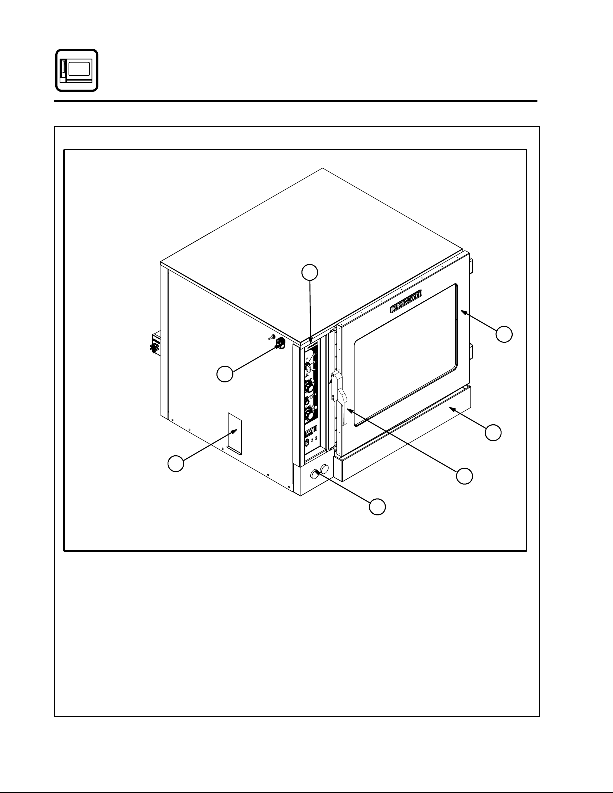
Oven Features
Optional
Semi-Automatic
Deliming
BC14E shown
1
3
6
1 Control Panel
2 Power Connection
(BC14E and BC14EDS only)
3 Oven Door
4 Drip Collector
5 Door Handle
4
2
5
7
Figure 1
6 Deliming Port
(BC14E and BC14G only)
7Fuses
(BC14E only)
Gas Shutoff
(BC14G only)
4
Page 9
Installation
Agency Approvals
THE INSTALLATION INSTRUCTIONS CONTAINED HEREIN ARE FOR THE USE OF QUALIFIED INSTALLATION AND SERVICE PERSONNEL
ONLY. INSTALLATION OR SERVICE BY OTHER
THAN QUALIFIED PERSONNEL MAY RESULT IN
DAMAGE TO THE OVEN AND/OR INJURY TO
THE OPERATOR.
Qualified installation personnel are individuals, a
firm, a corporation, or a company which either in
person or through a representative are engaged
in, and are responsible for:
D The installation or replacement of gas piping.
The connection, installation, repair or servicing
of equipment.
D The installation of electrical wiring from the elec-
tric meter, main control box or service outlet to
the electric appliance.
Qualified installation personnel must be experiencedinsuchwork,befamiliarwithallprecautions required and have complied with all requirements of state or local authorities having
jurisdiction.
U.S. and Canadian Installations
Installation must conform with local codes, or in
the absence of local codes, with the National Fuel
Gas Code, NFPA54/ANSI Z223.1 ---Latest Edition,
the Natural Gas Installation Code CAN/CGAB149.1 or the Propane Installation Code, CAN/
CGA-B149.2 as applicable.
Reference: National Electrical Code, ANSI/NFPA
70---Latest Edition and/or Canadian Electrical
Code CSA C22.1 as applicable.
This equipment is to be installed in compliance
with the Basic Plumbing Code of the Building Offi-
cials and Code Administrators International Inc.
(BOCA) and the Food Service Sanitation Manual of
the Food and Drug Administration (FDA).
General Export Installations
Installation must conform with Local and National
installation standards. Local installation codes and/
or requirements may vary. If you have any questions
regarding the proper installation and/or operation of
your appliance, please contact your local distributor.
If you do not have a local distributor, please call
Blodgett Combi at 0011-802-860-3700.
5
Page 10
Installation
Owner’s Responsibilities
Installation responsibilities prior to service
startup inspection
You are entitled to a free start-up inspection service by our factory ASAP. Before a factory representative arrives to perform a startup procedure,
the owner must already have satisfied the following requirements.
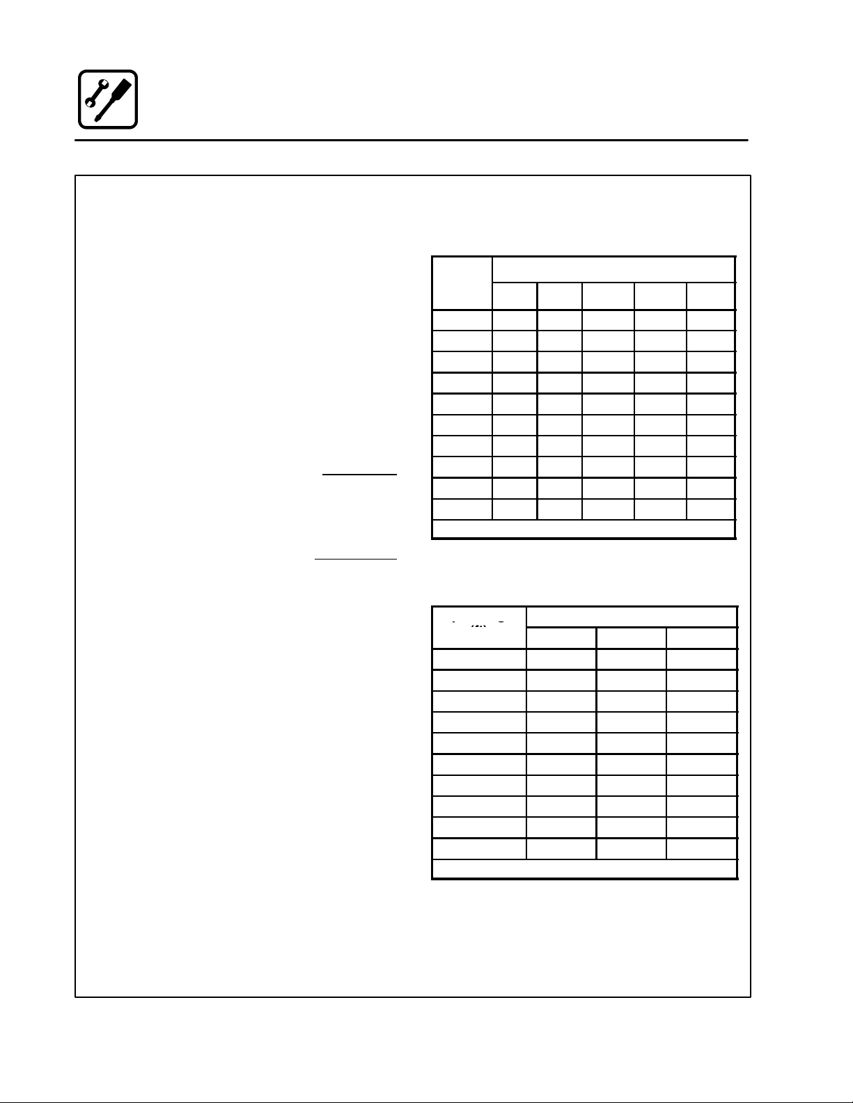
PLUMBING SPECIFICATIONS -- BC14E/AA, BC14G/AA,
BC14EDS/AA, BC14GDS/AA and B14G/AB
Water
Water Pressure 30 PSI (207 kPa) minimum
Water Connection 3/4” Hose Hot and Cold Water
Water Pressure Regulator Setting BC-14E/G --- Preset to 30 PSI (207 kPa)
Minimum Requirements TDS --- less than 100 parts per million
1. Oven(s) are uncrated, stacked (if applies) and
put in place.
NOTE: Please refer to Leg Attachment and
Stacking.
Maximum shelf loading -- 60 lbs (27.3 Kg)
50 PSI (345 kPa) maximum
B-14G --- Preset to 3 PSI (21 kPa)
Total Hardness --- 80-120 parts per million
C h lor i d es --- le s s t h a n 3 0 p a r t s p e r m i llion
pH Factor --- 7.0-8.0
Drainage Atmospheric Vented Drain
Drain Connection 2.00” (50.8mm) Copper
Avg Water Drain Temp. Approximately 160_F(71_C)
STEAM SPECIFICATIONS -- BC14EDS/AA and BC14GDS/AA
Steam Pressure 40 PSI (276 kPa) minimum
50 PSI (345 kPa) maximum
Steam Volume 60 lbs/hour per cavity
6
Page 11
Installation
HotA
i
BTU/H
HotA
i
BTU/H
Owner’s Responsibilities
RATINGS -- GAS APPLIANCES -- BC14G/AA
Gas Type Gas Input Voltag e Phase Amps Motor
U.S. and Canadian Installations
Natural Steam --- 55,000 BTU/Hr
r --- 65,000
Total --- 115,000 BTU/Hr
Propane Steam --- 48,000 BTU/Hr
r --- 65,000
Total --- 113,000 BTU/Hr
3/4” FNPT connector for all U.S. and Canadian installations
RATINGS -- GAS APPLIANCES -- BC14GDS/AA
Gas Type Gas Input Voltag e Phase Amps Motor
U.S. and Canadian Installations
Natural 65,000 BTU/Hr
Propane 65,000 BTU/Hr
3/4” FNPT connector for all U.S. and Canadian installations
RATINGS -- GAS APPLIANCES -- B14G/AB
208-240 1 15 1/2HP 208-240VAC, 50/60 Hz
r
120 1 15 1/2HP 208-240VAC, 50/60 Hz
208-240 1 15 1/2HP 208-240VAC, 50/60 Hz
r
120 1 15 1/2HP 208-240VAC, 50/60 Hz
208-240 1 15 1/2HP 208-240VAC, 50/60 Hz
120 1 15 1/2HP 208-240VAC, 50/60 Hz
208-240 1 15 1/2HP 208-240VAC, 50/60 Hz
120 1 15 1/2HP 208-240VAC, 50/60 Hz
Gas Type Gas Input Voltag e Phase Amps Motor
U.S. and Canadian Installations
Natural 65,000 BTU/Hr 120 1 15 1/2HP 208-240VAC, 50/60 Hz
Propane 65,000 BTU/Hr 120 1 15 1/2HP 208-240VAC, 50/60 Hz
3/4” FNPT connector for all U.S. and Canadian installations
7
Page 12

Installation
Owner’s Responsibilities
RATINGS -- ELECTRIC APPLIANCES -- BC14E/AA and BC14EDS/AA
Vol tage Hz Phase
208 60 1 89 89 --- 1/2HP 208-240VAC, 50/60 Hz
208 60 3 52 52 52 1/2HP 208-240VAC, 50/60 Hz
240 60 1 82 82 --- 1/2HP 208-240VAC, 50/60 Hz
240 60 3 47 47 47 1/2HP 208-240VAC, 50/60 Hz
480 60 3 23 23 23 1/2HP 208-240VAC, 50/60 Hz
380/220 50 3 25 25 25 1/2HP 208-240VAC, 50/60 Hz
415/240 50 3 27 27 27 1/2HP 208-240VAC, 50/60 Hz
400/230 50 3 26 26 26 1/2HP 208-240VAC, 50/60 Hz
Max Load (amps)
L1 L2 L3
Motor
8
Page 13
Installation
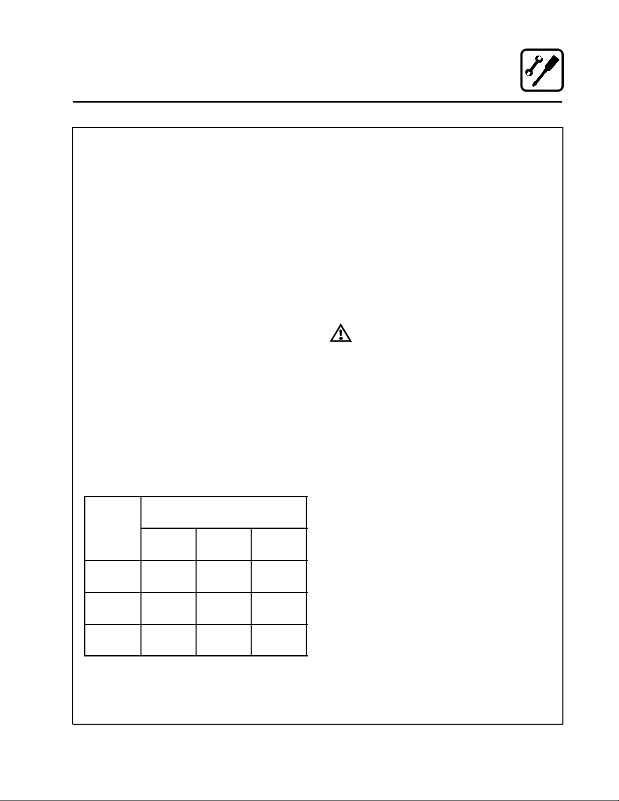
Oven Location and Ventilation
OVEN LOCATION
The well planned and proper placement of your
oven will result in long term operator convenience
and satisfactory performance.
Certain minimum clearances must be maintained
between the oven and any combustible or noncombustible construction. See the table below.
In addition, the following clearances are recommended for servicing.
D Oven body sides --- 12” (30cm)
D Oven body back --- 12” (30cm)
NOTE: On gas models, routine servicing can usu-
ally be accomplished within the limited
movement provided by the gas hose restraint. If the oven needs to be moved fur ther from the wall, the gas must first be
turned off and disconnected from the oven
before removing the restraint. Reconnect
the restraint after the oven has been returned to its normal position.
Left Side Heat Shield
Heat sources should not be near the air vents located on the left hand side of the gas appliance.
Consult the factory for optional protective side
heat shield.
BC14 and BC14DS P/N R9527
MINIMUM REQUIRED
Oven
Model
Right
Side
BC14E
BC14EDS1”(25.4mm)4”(101.6mm)6”(152.4mm)
BC14G
BC14GDS1”(25.4mm)6”(152.4mm)6”(152.4mm)
B14G 0”
(0mm)*
CLEARANCES
Left
Side
0” (0mm) 6”
Back
(152.4mm)
VENTILATION
The necessity for a properly designed and installed ventilation system cannot be over emphasized. The ventilation system will allow the unit to
function properly while removing unwanted vapors and products of combustion from the operating area.
The appliance must be vented with a properly designed mechanically driven exhaust hood. The
hood should be sized to completely cover the
equipment plus an overhang of at least 6” (15 cm)
on all sides not adjacent to a wall. The capacity of
the hood should be sized appropriately and provisions made for adequate makeup air.
WARNING!!
Failure to properly vent the oven can be
hazardous to the health of the operator;
and will result in operational problems,
unsatisfactory baking, and possible damage to the equipment. Damage sustained
as a direct result of improper ventilation
will not be covered by the Manufacturer’s
warranty.
U.S. and Canadian Installations
Refer to your local ventilation codes. In the absence of local codes, refer to the National ventilation code titled, “Standard for the Installation of
Equipment for the Removal of Smoke and Grease
Laden Vapors from Commercial Cooking Equipment”, NFPA-96- Latest Edition.
General Export Installations
Installation must conform with Local and National
installation standards. Local installation codes
and/or requirements may vary. If you have any
questions regarding the proper installation and/or
operation of your unit, please contact your local
distributor. If you do not have a local distributor,
please call Blodgett Combi at 0011-802-860-3700.
* 0” (0mm) clearance from hose hooks
9
Page 14
Installation
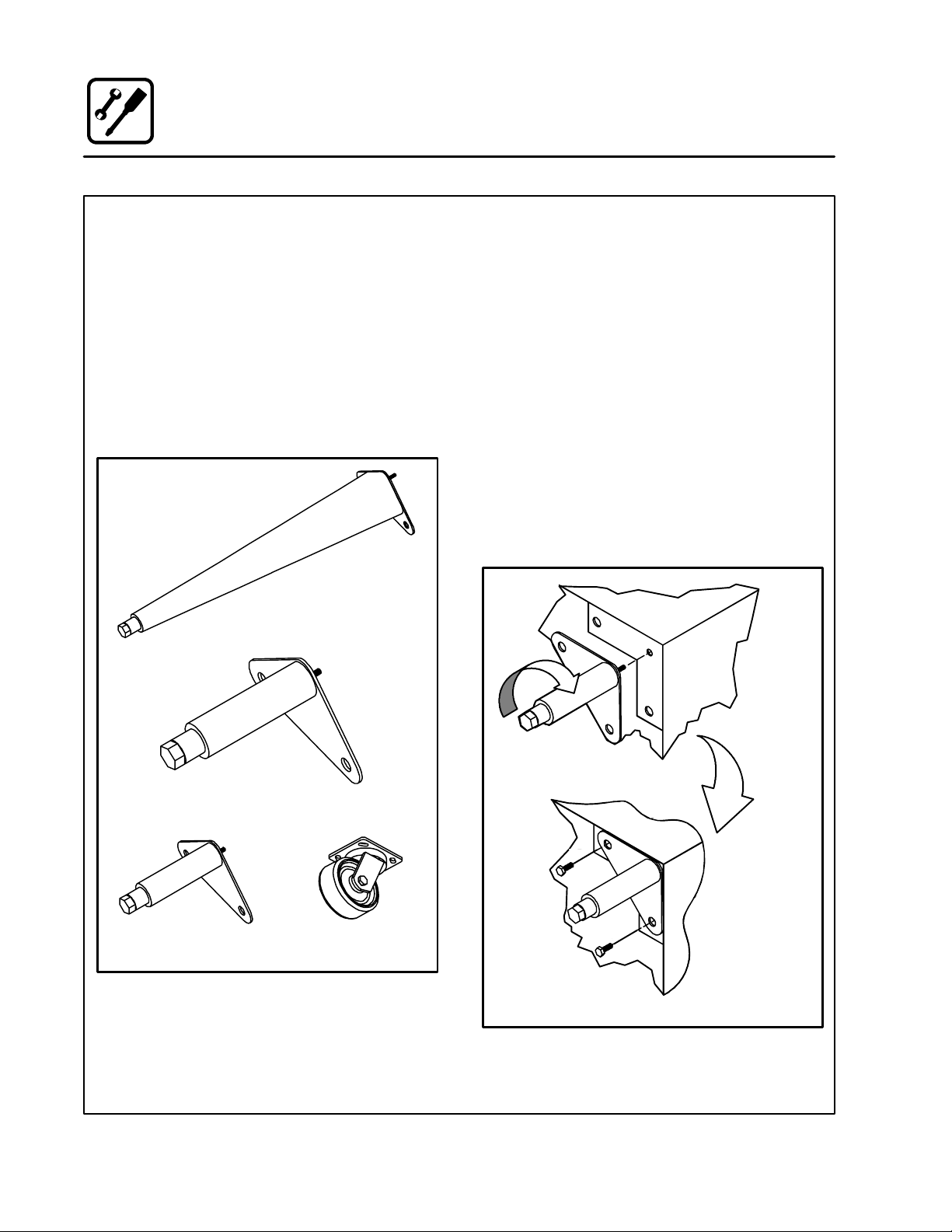
Leg Attachment
LEG OPTIONS
Legs are available in 4” (101mm), 6” (152mm) or
25” (635mm) lengths or low profile casters.
D The 4” (101mm) legs may be used when mount-
ing on a counter.
D The 6” (152.4mm) legs are used on the lower
section of a double stacked appliance.
D The 25” (635mm) legs are used for a single ap-
pliance located on the floor.
NOTE: For safety reasons, casters must not be
used with the 25” (635mm) legs.
25” (635mm) Adjustable Leg
ATTACHMENT
1. Align the threaded stud on one of the front
legs to the bolt hole located in the bottom corner of the appliance. Turn the leg clockwise
and tighten to the nearest full turn.
2. Align the leg plate holes with the bolt holes.
Secure with the two 1/2” bolts provided.
3. Repeat the above steps with the other front
leg. If low profile casters are used, install them
with the locking casters in the front of the oven.
The rear casters do not lock. Ensure that the
locksaresetonthefrontcasters.
4. Tip the oven up on the newly installed front
legs. If casters are used, check that the locks
aresetonthefrontcasters.Repeat the above
steps for the rear legs.
5. Level the oven by screwing the adjustable feet
in or out as necessary.
6” (152,4mm) Adjustable Leg
4” (101mm) Leg
Figure 2
Low Profile Casters
Figure 3
10
Page 15
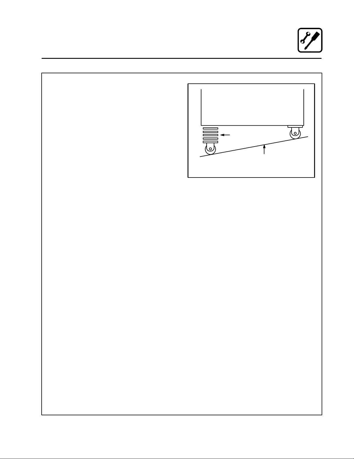
1. Placealevelonthefloorwherethecastersare
to rest.
2. Place shims under the low side until it is level.
3. Mount the shims between the casters and the
oven as follows:
a.) Align the shims and caster holes with the
bolt holes.
b.) Secure with the 1/2” bolts provided.
NOTE: Install them with the locking casters in
the front of the oven. The rear casters
do not lock. Ensure that the locks are
setonthefrontcasters.
4. Tip the oven up on the newly installed casters.
Installation
Caster Attachment
Add shims as necessary
Floor
Exaggerated for clarity
Figure 4
11
Page 16
Installation
Stacking
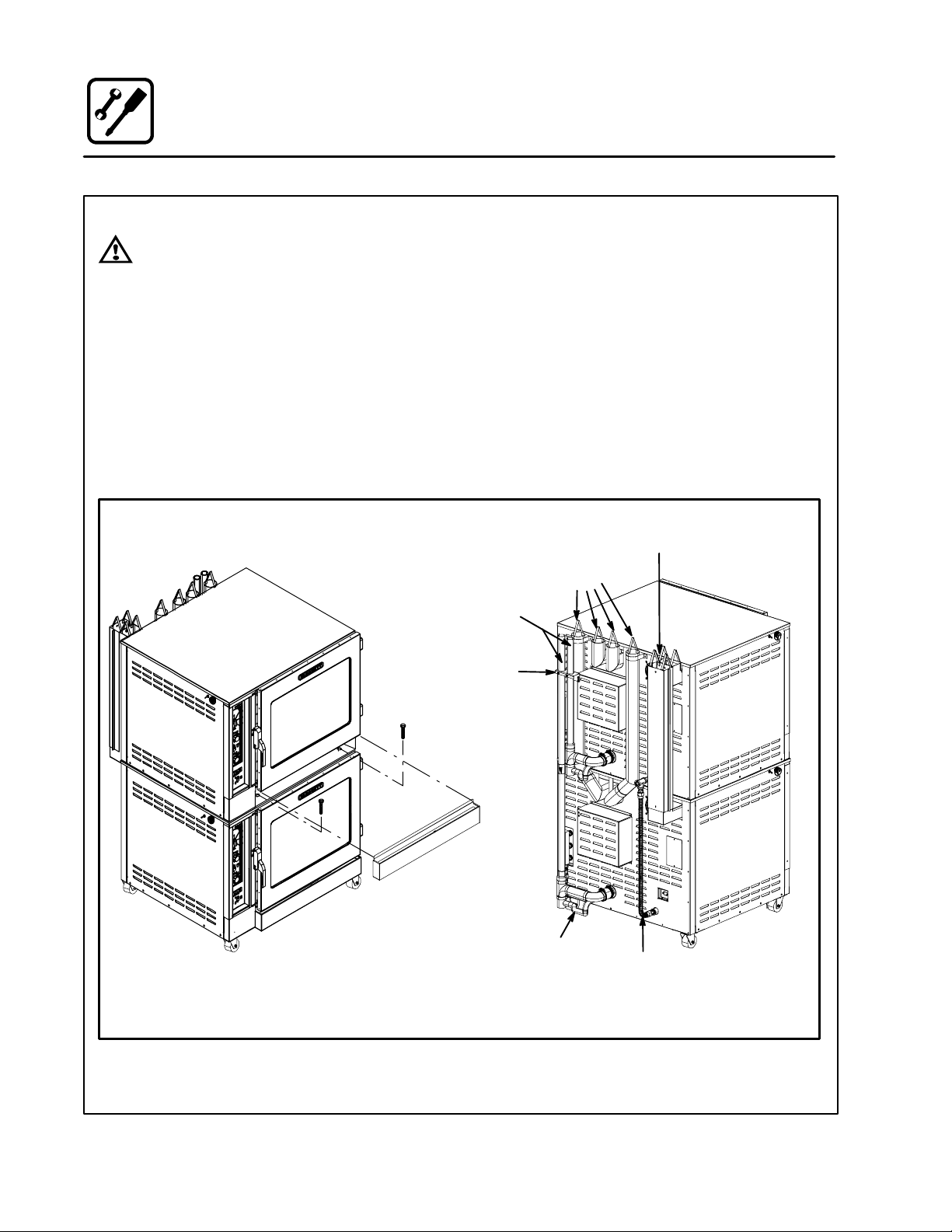
WARNING!!
Stacking should be performed by qualified installation personnel only. The appliances are heavy. Take care to use proper tools and techniques when lifting and
stacking appliances.
1. Removethedrippanfromthetopappliance.
2. Attach the legs or casters to the bottom appliance.Seepage10.
3. Place the top appliance on the bottom appliance. Be sure all four sides are flush.
4. Bolt the two appliances together using the
bolts provided.
5. GAS APPLIANCES ONLY: Attach the flue
ventsasshown.
NOTE: For electric appliances proceed to
step 6.
6. Replace the drip pan. Push to the right until it
stops. The right side should overhand the oven.
7. Connect the drain, gas (if applicable), electrical and water. Refer to pages 14--- 18.
NOTE: An optional gas manifold may be purchased
from Blodgett Combi. Order part number
R9570.
Steam Generator Flue
(BC14 only)
Gas Oven
Hot Air Flue
Drain Assembly/
Steam Vent
Mounting
Bracket
Drip Pan
BC14G Shown
1.125” I.D. Hose
from Drip Pan Drain
Optional
Gas Plumbing
Manifold
Rear View
Figure 5
12
Page 17
Installation
Oven Leveling and Steam Connection
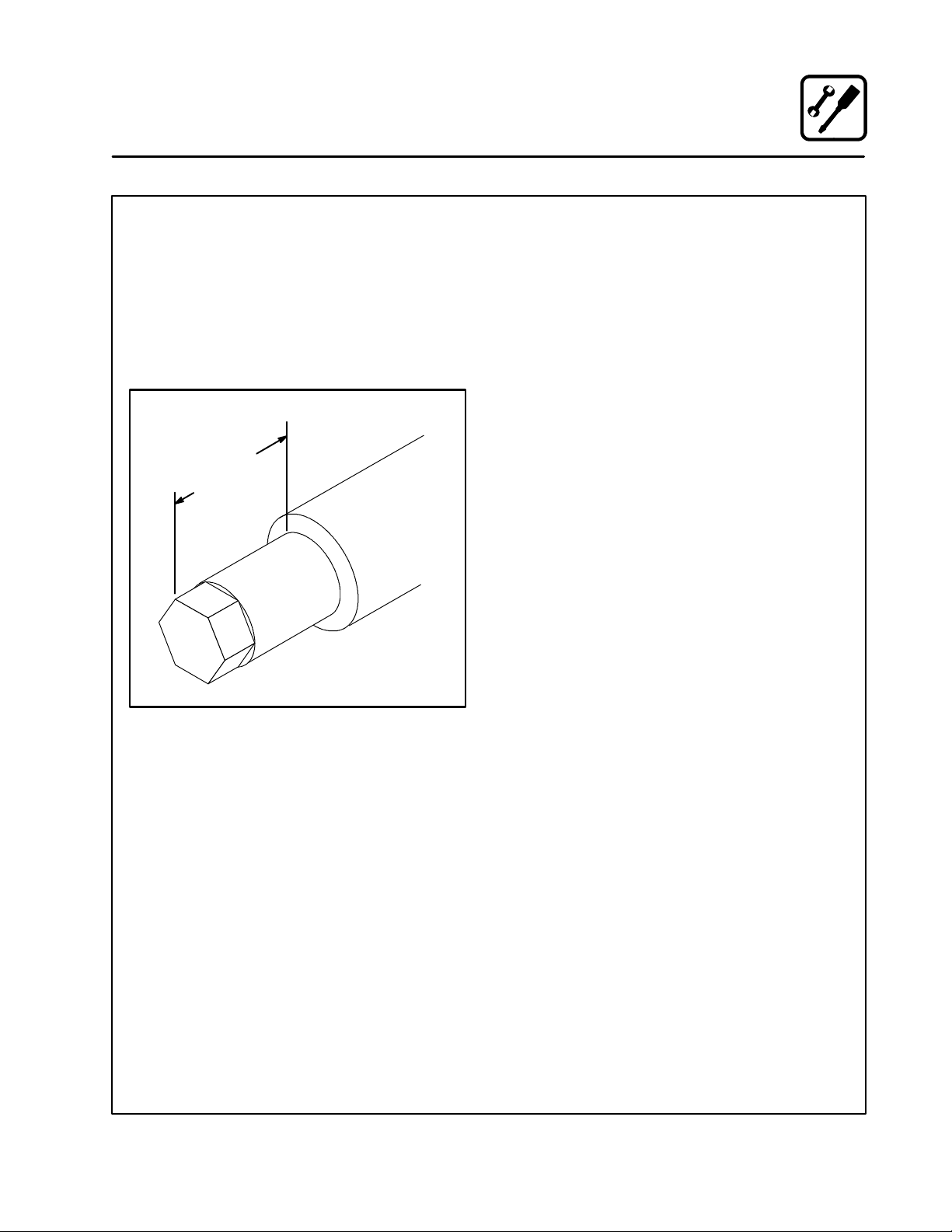
OVEN LEVELING
This oven should be set up in place.
With any stand or oven, be certain that the surface
is level, even and solid. A sloped or uneven base
may cause the appliance to function improperly.
Minor unevenness can be corrected by adjusting
the metal leg feet. The maximum adjustment of the
leg feet is 1-3/8” (35mm).
Maximum
Adjustment
1-3/8” (35mm)
Leg
Foot
STEAM CONNECTION
NOTE: BC14EDS and BC14GDS only.
Connect the appliance to a 40 to 50 psi maximum
external steam source per local or state codes.
The steam must be clean, potable and fit for human consumption. Failure to connect this appliance to a suitable steam source will revoke the
sanitation approval.
Steam supply line is 3/4” NPT. A particle screen
and bucket trap are recommended. 60 lbs per
hour is the maximum usage per oven. Steam supply pressure should not exceed 40 to 50 psi. The
flow pressure is 1-1/2 to 3-1/2 psi and is set at the
steam pressure regulator supplied inside the
oven.
Figure 6
13
Page 18
Installation
Plumbing Connections
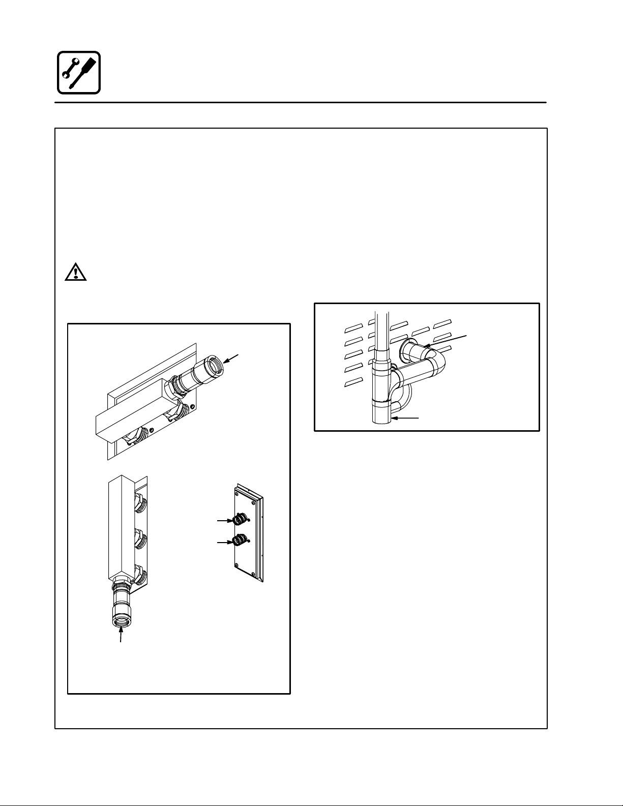
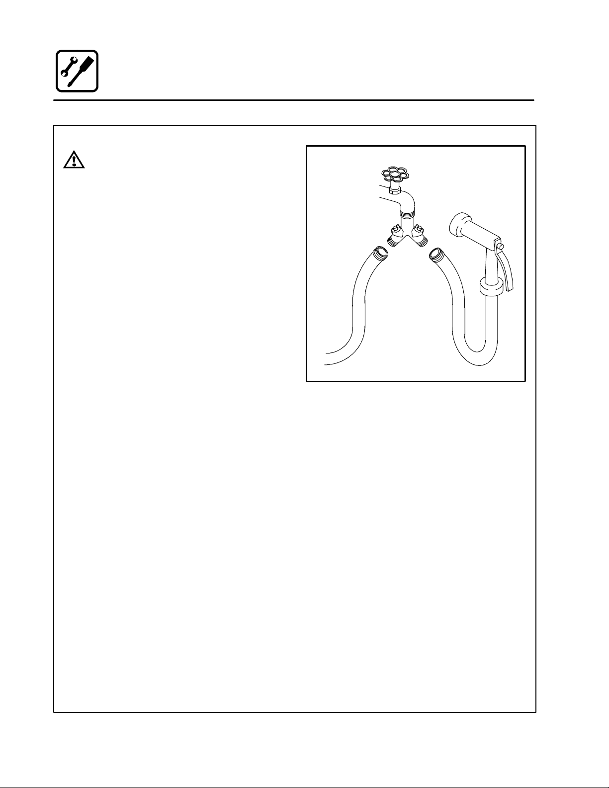
WATER CONNECTION
NOTE: Hot water maximizes steam production but
is not required. Cold water may be supplied
to both inlets if hot water is not available.
Connect the appliance to quality water via a pressure hose with 3/4” (19mm) couplings. See
Figure 7 for connections. A shut off valve is to be
provided adjacent to the oven.
WARNING!!
Operating the appliance without the water
regulator installed will invalidate your warranty.
Cold
Water
BC14E
Filtered
Connection
Unfiltered
Connection
BC14G
Cold Water
Water Connections
Rear of Appliance
B14G
Cold Water
DRAIN CONNECTION
The steam vent assemblies are constructed of 2”
DWV copper piping reduced to 1-1/2 DWV pipe.
The steam vent should be run to an open floor
drain avoiding flexible hose that could sag and allow trapped water to accumulate. The customer
must supply the piping from the oven to the drain.
Connect the drip pan drain to the steam vent with
1.125 I.D. hose.
Use the drain vent assembly and a 2” (50.8mm)
pipe for drain connection.
Coupling
Customer supplied
2” (50.8mm) drain
waste vent piping
Figure 8
Specific water/drain connection for City of Los
Angeles
1. Each drain line from the appliance shall be
routedwithoutdipsorsagstoterminateabove
the flood level rim of an approved indirect waste
receptor.
2. The appliance shall be installed in accordance
with the manufacturer’s printed instructions
and the LAPC and LAMC, 1999 editions.
3. A backflow protection device may be required
by local codes. If so, install on the potable water
system directly ahead of the appliance. The
backflow protection device shall be any of the
following: an approved pressure type vacuum
breaker installed at least 12” above the highest
point of use, a double check valve backflow preventer or a reduced pressure principal backflow
preventer.
Figure 7
14
Page 19
Installation
Electrical Connections
ELECTRICAL CONNECTION
All Models
NOTE: Electrical connections must be performed
by a qualified installer only.
Before making any electrical connections to these
appliances, check that the power supply is adequateforthevoltage,amperage,andphaserequirements stated on the rating name plate
mounted on the appliance.
The circuit breaker that is used to provide power
to this appliance must have a minimum of .076”
(3mm) contact spacing. The circuit breaker must
meet all Local and National installation standards.
All appliances must be installed in accordance
with Local or National Electrical codes.
A wiring schematic is located on the inside of the
removeable side panel.
NOTE: Disconnect the power supply to the ap-
pliancebeforeservicing.
WARNING!!
Improper installation may invalidate your
warranty.
Electric Models
A strain relief for the power supply cord is required.
The installer must supply a cord bushing that meets
all Local and National installation standards.
Gas Models
U.S. and Canadian Installations
A power cord (115V or 230V) is supplied with a
plug attached. Plug the power cord into the desired receptacle.
WARNING!!
If the supply cord is damaged, it must be
replaced by a special cord or assembly
available from the manufacturer or its service agent.
15
Page 20
Installation
L
t
h
p
g
Gas Connections
GAS PIPING
A properly sized gas supply system is essential for
maximum oven performance. Piping should be
sized to provide a supply of gas sufficient to meet
the maximum demand of all appliances on the line
without loss of pressure at the equipment.
Example:
NOTE: BTU values in the following example are
for natural gas.
You purchase a BC14G to add to your existing
cook line.
1. Add the BTU rating of your current appliances.
Pitco Fryer 120,000 BTU
6 Burner Range 60,000 BTU
Deck Oven 50,000 BTU
Total 230,000 BTU
2. Add the BTU rating of the new oven to the total.
Previous Total 230,000 BTU
BC14G 115,000 BTU
New Total 345,000 BTU
3. Measure the distance from the gas meter to
the cook line. This is the pipe length. Let’s say
thepipelengthis30’(9m)andthepipesize
is 1” (2.54 cm).
4. Use the appropriate table to determine the total capacity of your current gas piping.
The total capacity for this example is 375,000
BTU. Since the total required gas pressure,
345,000 BTU is less than 375,000 BTU, the
current gas piping will not have to be increased.
NOTE: The BTU capacities given in the tables are
for straight pipe lengths only. Any elbows
or other fittings will decrease pipe capacities. For example: a schedule 40 1-1/2” ell
fitting has an equivalent capacity of 4.2”
(10.2 cm) of straight pipe. Contact your local gas supplier if you have any questions.
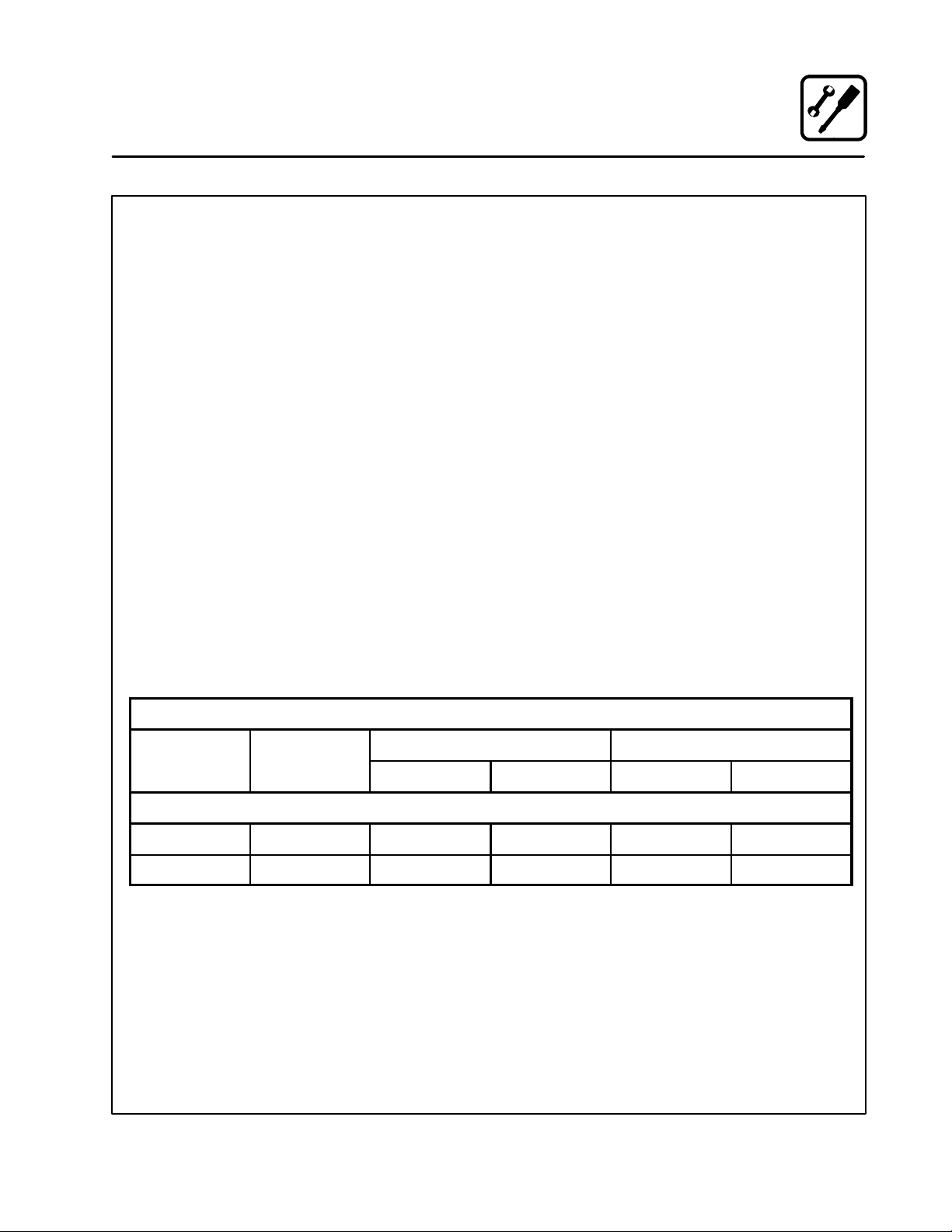
Maximum Capacity of Iron Pipe in Cubic Feet
of Natural Gas Per Hour
(Pressure drop of 0.5 Inch W.C.)
Pipe
eng
(ft)
10 360 680 1400 2100 3950
20 250 465 950 1460 2750
30 200 375 770 1180 2200
40 170 320 660 990 1900
50 151 285 580 900 1680
60 138 260 530 810 1520
70 125 240 490 750 1400
80 118 220 460 690 1300
90 110 205 430 650 1220
100 103 195 400 620 1150
From the National Fuel Gas Code Part 10 Table 10-2
Maximum Capacity of Pipe in Thousands of
BTU/hr of Undiluted P.P. Gas at 11” W.C.
Pipe Length
From the National Fuel Gas Code Part 10 Table 10-15
3/4” 1” 1-1/4” 1-1/2” 2”
(Pressure drop of 0.5 Inch W.C.)
(ft)
10 608 1146 3525
20 418 788 2423
30 336 632 1946
40 287 541 1665
50 255 480 1476
60 231 435 1337
70 215 404 1241
80 198 372 1144
90 187 351 1079
100 175 330 1014
Nominal Size, Inches
Inside Diameter, Inches
3/4” 1” 1-1/2”
16
Page 21
Installation
Gas Connections
PRESSURE REGULATION AND TESTING
The gas pressure to the appliance must be rated
for each appliance while the burners are on. A sufficientgaspressuremustbepresentattheinletto
satisfy these conditions. Refer to the table below
for correct gas pressure.
Each appliance has been adjusted at the factory
to operate with the type of gas specified on the rating plate attached to the right side of the appliance.
Each oven is supplied with a regulator to maintain
the proper gas pressure. The regulator is essen-
tial to the proper operation of the oven and
should not be removed.
DO NOT INSTALL AN ADDITIONAL REGULATOR
WHERE THE UNIT CONNECTS TO THE GAS
SUPPLY UNLESS THE INLET PRESSURE IS
GREATER THAN 14” W.C. (1/2 PSI) (37mbar).
The oven and its individual shutoff valve must be
disconnected from the gas supply piping system
during any pressure testing of that system at test
pressuresinexcessof1/2psig(3.45kPa).
The oven must be isolated from the gas supply
piping system by closing its individual manual
shutoff valve during any pressure testing of the
gas piping system at test pressures equal or less
than 1/2 psig (3.45kPa).
Prior to connecting the appliance, gas lines
should be thoroughly purged of all metal filings,
shavings, pipe dope, and other debris. After connection, the appliance must be checked for correct gas pressure.
U.S. and Canadian Installations
Installation must conform with local codes, or in
the absence of local codes, with the National Fuel
Gas Code, NFPA54/ANSI Z223.1 ---Latest Edition,
the Natural Gas Installation Code CAN/CGAB149.1 or the Propane Installation Code, CAN/
CGA-B149.2 as applicable.
General Export Installations
Installation must conform with Local and National
installation standards. Local installation codes and/
or requirements may vary. If you have any questions
regarding the proper installation and/or operation of
your appliance, please contact your local distributor.
If you do not have a local distributor, please call
Blodgett Combi at 0011-802-860-3700.
GAS PRESSURE
Gas
Typ e Pressure
U.S. and Canadian Installations
Natural 7 --- 1 4 ” W. C . .0531” dia .042” dia 3.5” W.C. 3.5” W.C.
Propane 12 ---14” W.C. .032” dia .026” dia 10.0” W.C. 10.0” W.C.
Inlet
Orifice Size at Sea Level Manifold Pressure
Hot Air Steam Hot Air Steam
17
Page 22
Installation
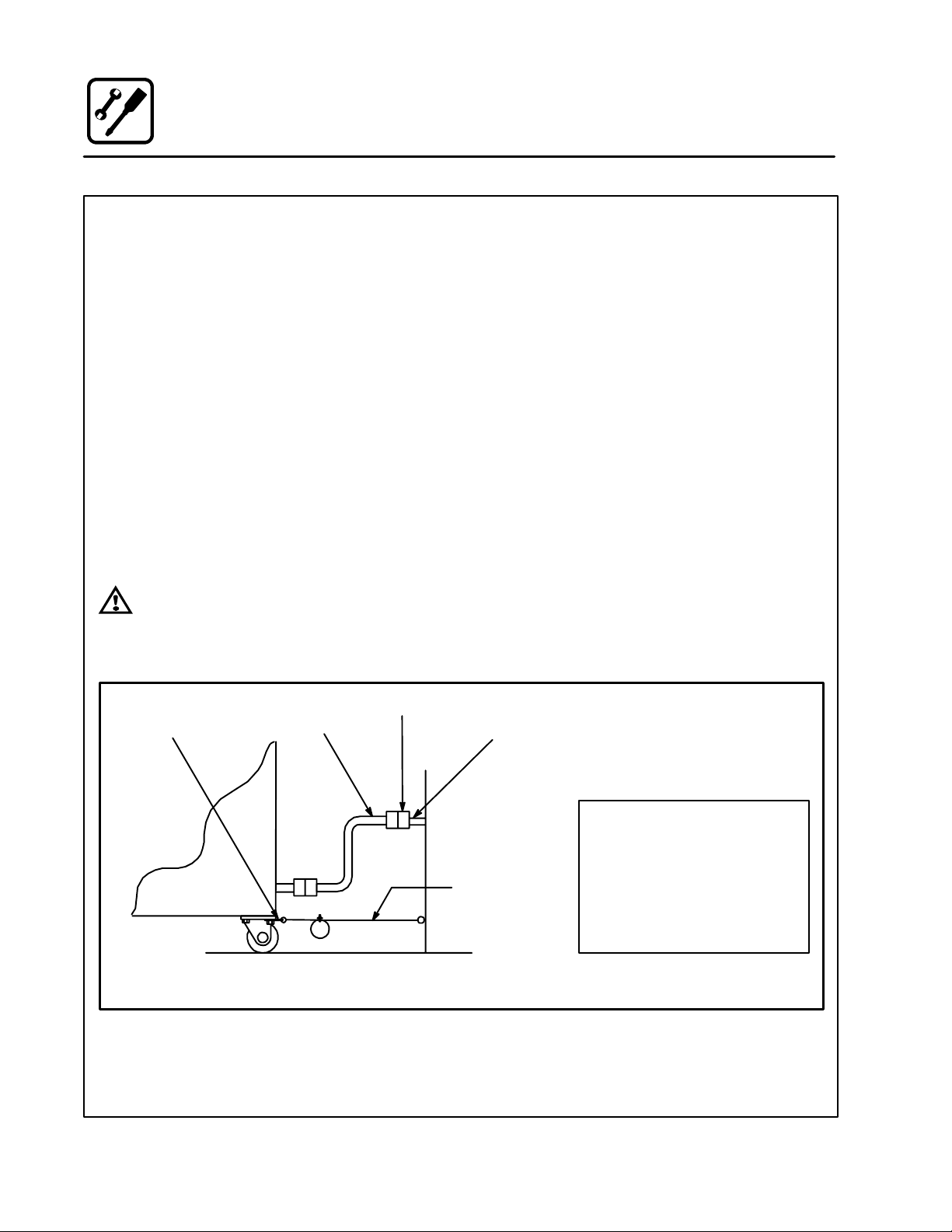
Gas Hose Restraint
If the appliance is mounted on casters, a commercial flexible connector with a minimum of 3/4” (1.9
cm) inside diameter must be used along with a
quick connect device.
A restraint must be used to limit the movement of
the appliance so that no strain is placed upon the
flexible connector. The restraint should be fastened to the base frame of the oven as close to the
flexible connector as possible. It should be short
enough to prevent any strain on the connector.
With the restraint fully stretched the connector
should be easy to install and quick connect.
The restraint (ie: heavy gauge cable) should be attached without damaging the building. DO NOT
use the gas piping or electrical conduit for the attachment of the permanent end of the restraint!
Use anchor bolts in concrete or cement block. On
wooden walls, drive hi test wood lag screws into
the studs of the wall.
WARNING!!
If the restraint is disconnected for any reason it must be reconnected when the appliance is returned to its original position.
U.S. and Canadian installations
The connector must comply with the Standard for
Connectors for Movable Gas Appliances, ANSI
Z21.69 or Connectors For Moveable Gas Appliances CAN/CGA-6.16 and a quick disconnect
device that complies with the Standard for QuickDisconnect Devices for Use With Gas Fuel, ANSI
Z21.41 or Quick Disconnect For Use With Gas Fuel
CAN 1-6.9. Adequate means must be provided to
limit the movement of the appliance without depending on the connection and the quick disconnect device or its associated piping.
A drip leg must be used at each appliance. Refer
to NFPA54/ANSI Z223.1 - Latest Edition (National
Fuel Gas Code) for proper drip leg installation.
General export installations
Installation must conform with Local and National
installation standards. Local installation codes and/
or requirements may vary. If you have any questions
regarding the proper installation and/or operation of
your appliance, please contact your local distributor.
If you do not have a local distributor, please call
Blodgett Combi at 0011-802-860-3700.
Attachment Plate
(secure with leg mount bolt)
Gas Hose
Quick Connect
Gas Supply Line
Restraint
Installation of Gas Hose and Restraint
(Single Section Shown)
Figure 9
IMPORTANT: Cable restraint should
be fastened as close as possible to the
flexible connector and short enough to
prevent any strain on the flexible connector.
At maximum stretch of shortened restraint, the flexible connector should
be easy to installand quick to connect.
18
Page 23
Installation
Adjustments
Before applying power to the appliance for the first
time, check for the following conditions:
j All electrical safety provisions have been ad-
hered to and the electrical connections are
correct.
j Water is connected, turned on and all of the
connections are water tight.
j The pan holders are inserted into the oven
cavity.
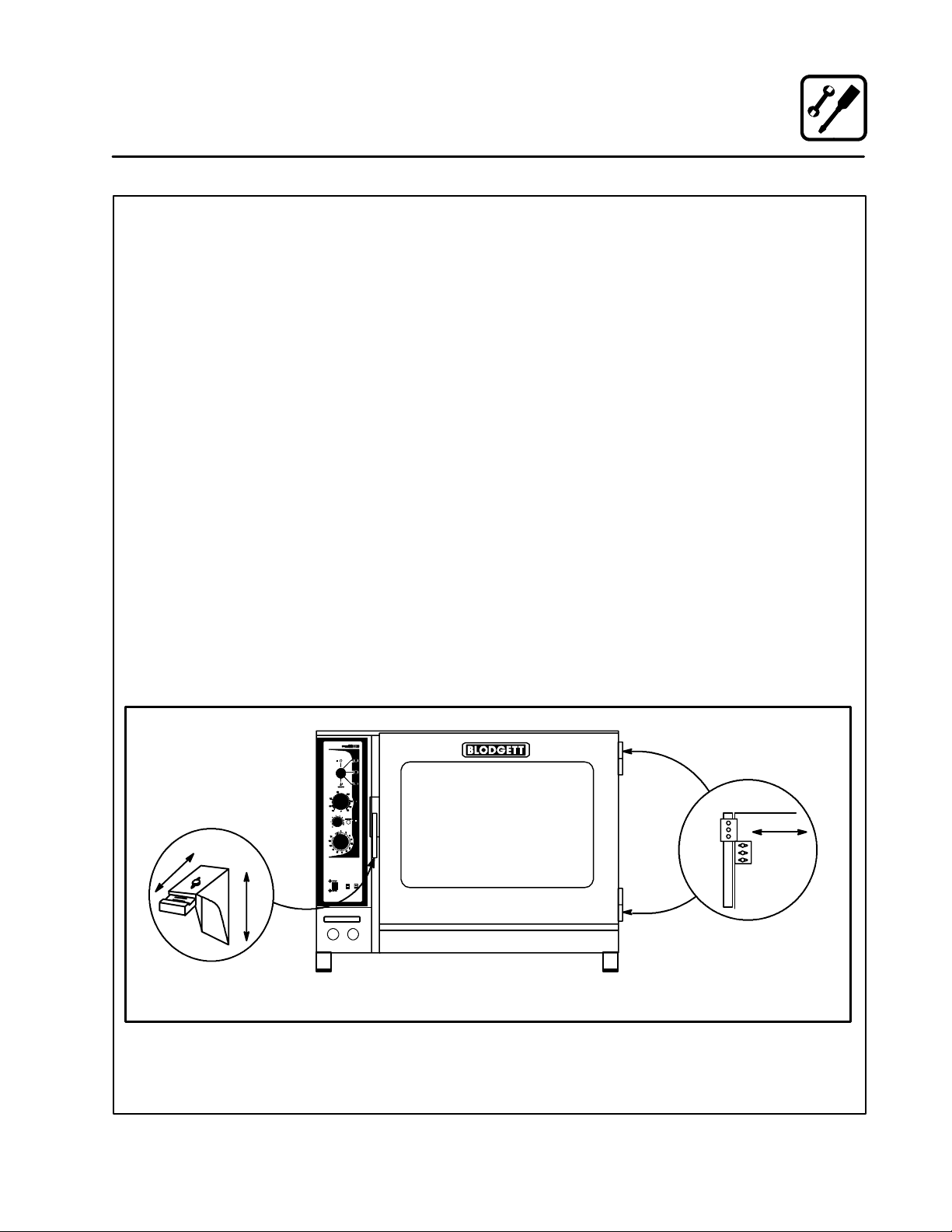
DOOR ADJUSTMENT
The door catch may be adjusted in four directions,
in and out, and up and down, using the following
procedure:
1. Adjust up and down by loosening the two
bolts holding the catch to the face of the appliance. See Figure 10 (A).
2. Make adjustments so that the leading face of
the latch is centered in the opening of the handle assembly.
3. Tighten the bolts so that there is no further
movement.
4. Adjust in and out by loosening the bolt on top
of the catch. See Figure 10 (B).
5. The adjustment face is stepped so that movement is limited with the bolt tightened properly.
6. The adjustment is correct when the door closes
firmly and no steam leaks from the gasket.
The hinges can also be adjusted as follows:
1. Be certain the latch is adjusted properly.
2. Adjust hinges so that the door back and the
appliance face are parallel. See Figure 10 (C).
3. The adjustment is correct when no steam
leaks through the gasket.
Door
B
A
BC14E Shown
Figure 10
19
C
Oven
Page 24
Installation
Final Check Lists
WARNING!!
Final check list must be performed by a
qualified installer only.
ELECTRICAL CONTROL COMPARTMENT
j Voltage to appliance matches rating plate
PLUMBING FINAL CHECK
j Incoming water pressure within appliance
specification.
j Atmospheric vented drain in place.
j Water solenoid properly bracketed and not
leaking.
j Water feed lines intact without leaks.
j Optional Spray Hose connected properly.
Connect the optional spray hose to the fill solenoid as shown.
Cold Water Supply
Hose and Spray
Option
To
Oven Fill
Manifold
Figure 11
20
Page 25

Installation
Final Check Lists
OVEN OPERATIONAL TESTS
NOTE: Checkstobemadebycustomerorautho-
rized service agent.
Cool Down Mode
j Check that the fan runs with the door open.
Steam Mode
Turn on STEAM mode and set thermostat to
steam. Verify the following:
j Heat demand lamp is on.
j Heat demand lamp shuts off at approximately
212_F (100_C).
j Check timer operation in all three positions
a.) Set timer to “OFF” position, buzzer should
sound.
b.) Set timer in position other than “OFF” or
“STAY ON”, timer should count down.
c.) Set timer in “STAY ON” position, oven
should operate continuously without timer.
j Run light (power light) turns on.
j Unit produces steam, window fogs, door seal
does not leak.
Hot Air Mode
Turn to HOT AIR mode and set thermostat to
400_F (204_C) and verify:
j Heat demand lamp is on.
j Oven is heating.
j Heat demand lamp shuts off at 400_F (204_C)
and oven maintains 400_F (204_C).
j Fan shuts off with door open.
Steam On Demand Mode
Turn the oven to Hot Air mode. Set Steam On Demand for 1 minute. Press the Steam On Demand
button and verify:
j Steam demand lamp is on.
j Steam demand lamp shuts off after approxi-
mately 1 minute.
Combi Mode
Turn to COMBI mode, set thermostat to 350_F
(177_C) and verify:
j Heat demand lamp is on.
j Oven is heating.
j Heat demand lamp shuts off at 350_F (177_C)
and oven maintains 350_F (177_C).
j Fan shuts off with door open.
21
Page 26
Operation
Safety Information for Gas Units
THE INFORMATION CONTAINED IN THIS SECTION IS PROVIDED FOR THE USE OF QUALIFIED
OPERATING PERSONNEL. QUALIFIED OPERATING PERSONNEL ARE THOSE WHO HAVE
CAREFULLY READ THE INFORMATION CONTAINED IN THIS MANUAL, ARE FAMILIAR WITH
THE FUNCTIONS OF THE OVEN AND/OR HAVE
HAD PREVIOUS EXPERIENCE WITH THE OPERATIONOF THE EQUIPMENT DESCRIBED. ADHERENCE TO THE PROCEDURES RECOMMENDED HEREIN WILL ASSURE THE
ACHIEVEMENT OF OPTIMUM PERFORMANCE
AND LONG, TROUBLE-FREE SERVICE.
Please take the time to read the following safety
and operating instructions. They are the key to the
successful operation of your Blodgett Combi appliance.
SAFETY TIPS
For your safety read before operating
What to do if you smell gas:
D DO NOT try to light any appliance.
D DO NOT touch any electrical switches.
D Use an exterior phone to call your gas supplier
immediately.
D If you cannot reach your gas supplier, call the
fire department.
What to do in the event of a power failure:
D Tur n al l s w it c he s to of f .
D DO NOT attempt to operate the appliance until
the power is restored.
NOTE: In the event of a shut-down of any kind, al -
low a five (5) minute shut off period before
attempting to restart the oven.
General safety tips:
D DO NOT use tools to turn off the gas control. If
the gas cannot be turned off manually do not try
to repair it. Call a qualified service technician.
D If the oven needs to be moved for any reason,
the gas must be turned off and disconnected
fromtheappliancebeforeremovingtherestraint cable. Reconnect the restraint after the
oven has been returned to its original location.
D DO NOT remove the control panel cover unless
the oven is unplugged.
22
Page 27
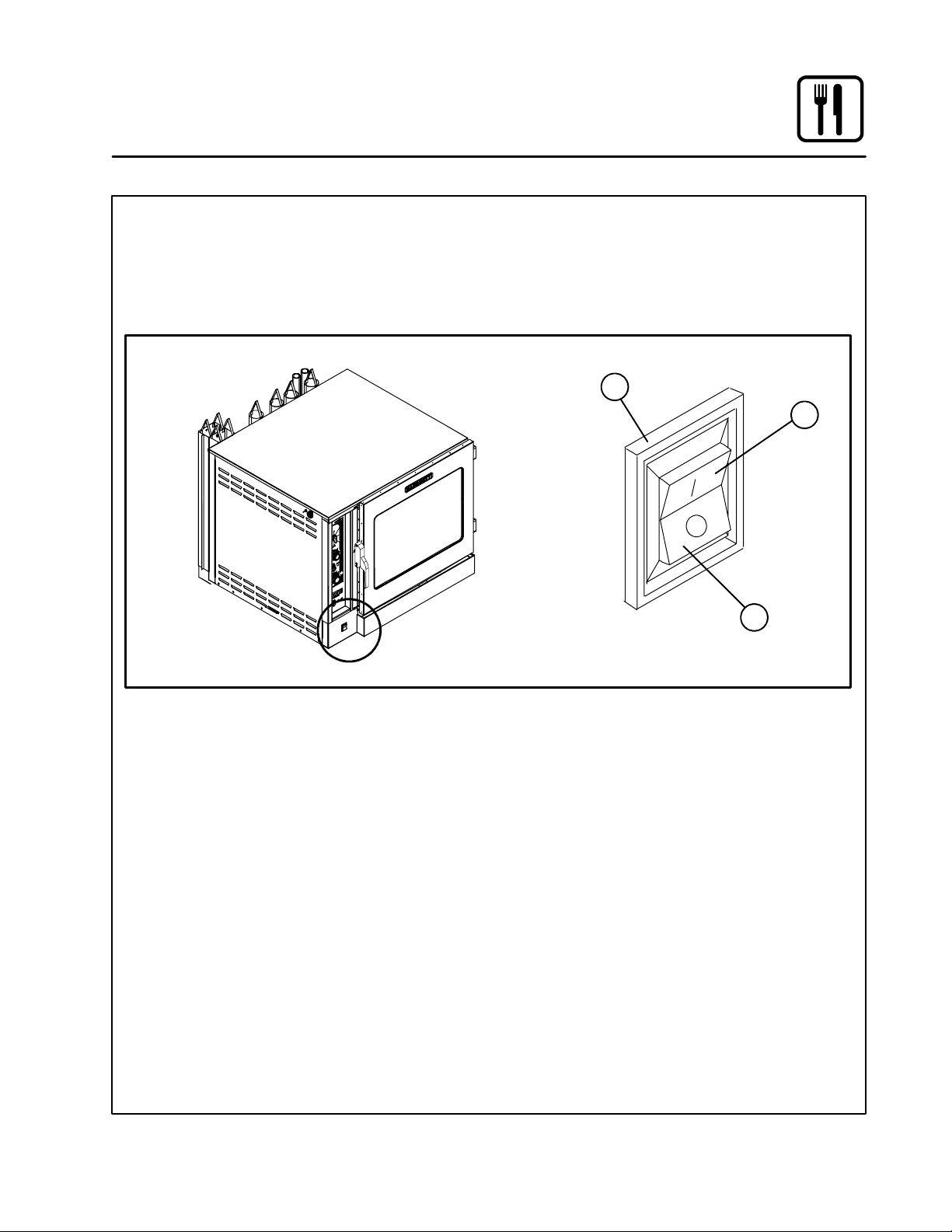
CONTROLS IDENTIFICATION
1. GAS CONTROL SWITCH --- U s e d t o t u r n ga s
on or off.
2. GAS ON POSITION --- Press the switch into
the I position.
Operation
Gas Controls
3. GAS OFF POSITION --- Press the switch into
the O position.
1
2
See View A
3
BC14G Shown
Figure 12
23
Page 28
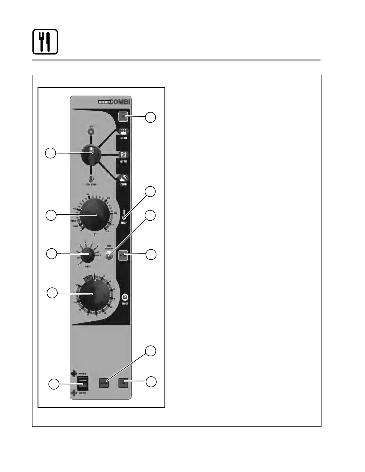
Operation
Standard Controls
2
3
5
8
CONTROLS IDENTIFICATION
1. POWER ON LAMP --- when lit indicates power
to the unit is turned on.
1
4
6
7
2. MODE SELECTOR SWITCH --- t u r n s p o w e r
to the oven on or off. Allows selection of
Steam, Hot Air, Combi or Cool Down Modes.
3. TEMPERATURE DIAL --- used to set desired
cooking temperature.
4. HEAT ON LIGHT --- When lit indicates that the
unit is heating. The light goes off when the unit
has reached the set temperature.
5. STEAM ON DEMAND TIMER --- u s e d t o s e t
steam time
6. STEAM ON DEMAND SWITCH --- u s e d t o i n i -
tiate steam injection cycle
7. STEAM ON DEMAND LAMP --- i l l u m i n a t e d
when steam on demand is activated.
8. TIMER DIAL --- used to set desired cook time.
9. FAN SPEED SWITCH --- used to select low or
high speed.
10. DELIME LAMP --- Flashes when steam gener-
ator deliming is needed. Remains steady
when deliming process is active.
NOTE: BC14DS and B14G do not have a de-
lime lamp.
11. BC14 FILL LAMP --- illuminated until the
steam generator is filled with water
NOTE: BC14DS does not have a fill lamp.
B14 CLEAN OVEN LAMP --- i n f o r m s u s e r t o
clean oven, including behind the fan guard
and fan
10
9
Figure 13
11
24
Page 29

Operation
Standard Controls
OPERATION
1. Turn the MODE SELECTOR Switch (2) to the
desired function.
2. Set the TIMER (8) to ON.
3. For the HOT AIR and COMBI modes, set the
TEMPERATURE Dial (3) to the desired cook
temperature.
NOTE: The optimum temperature for Combi
mode is 300-350
ForSTEAM mode set the TEMPERATURE Dial
(3) no higher than 212_F (100_C).
NOTE: For steaming use 212
poaching turn the temperature dial to
the POACH position, 180
4. Once the oven is preheated, place the food inside and close the door.
5. Set the TIMER (8) for the desired cook time.
6. The selected mode operates automatically.
Thetemperature,timeandmodecanbealtered at any time during the cooking process.
The operation can be stopped by the use of
the Mode Selector Switch or by opening the
door.
7. At the end of the specified time period, the
buzzer sounds and the appliance will shut off
automatically. Turn the TIMER (8) to the ON
position to stop the buzzer and restart the appliance in a continuous on mode. Or, simply
turn the mode switch to the off position.
8. To cool down the oven cavity, switch the
MODE SELECTOR Switch (2) to COOL DOWN.
In the Cool Down mode neither the temperature dial or the timer will be operational.
NOTE: The unit can be cooled down rapidly
for steaming, cleaning, etc. Open the
dor wide and select the cool down
mode. The oven will cool from
350---212
mately two minutes.
9. The mode selector switch is also the main
power switch. In the OFF position the appliance is not operational.
_
_
F (149-177_C).
_
F (100_C). For
_
F(82_C).
F (177 --- 100_C) in approxi-
Steam on Demand
How to set the Steam On Demand mode:
While in the Hot Air or Combi mode, the unit can
be set to steam for a timed period. At the end of the
timed cycle the unit reverts back to the original setting. Steam On Demand can be used at any time
during the cook cycle.
NOTE: Steam On Demand is not available in
steam mode.
1. Set the desired “steam on” time with the
STEAM ON DEMAND TIMER (5).
2. Press the STEAM ON DEMAND SWITCH (6).
This feature is useful in many ways. A few are listed
below. Most of the ideas came from our creative
customers. Experiment with this feature on your
own and let us know of any new uses.
D Add a minute or two at the beginning when bak-
ing bread for a shiny crust.
D Kick start large loads such as 20 or more chick-
ens. By starting large loads with 5 to 8 minutes
of steam you help the oven recover and cut the
cooking time by more than 10%.
D Bake bagels without boiling. By starting raw ba-
gels with 1 to 2 minutes of steam you can
achieve a beautiful crust.
D Cream caramel is great at 230_F to 250_Finthe
Combi mode using 2 minutes of on demand
steam.
D When cooking chicken wings, try setting the
oven in the Combi mode at 375_F and use 3
minutes of Steam On Demand. This method will
stop the tips from burning. Total cooking time is
approximately 12 minutes.
D Pork ribs tend to pull off the bone better when
using 5--- 8 minutes of Steam On Demand. Try
ribs in the Combi mode at 350_F.
25
Page 30

Operation
Optional Cook & Hold
2
3
5
6
8
9 10
11 12
13 14
16
19
1
15
18
17
20
21
CONTROLS IDENTIFICATION
1. POWER ON LIGHT --- when lit indicates pow-
er to the unit is turned on.
2. MODE SELECTOR SWITCH --- c o n t r o l s pow e r
to the oven and selection of steam, hot air and
combi modes. The convection fan runs with the
switch in steam, hot air, combi or cool down.
3. TIME DISPLAY --- indicates cook time.
4. TIME ARROW KEYS --- press to enter cook
time from 00:00 to 99:59.
5. TEMPERATURE DISPLAY --- g i v e s c o o k t e m -
perature.
6. HEAT LIGHT --- when lit indicates hot air or
steam is in operation.
7. TEMPERATURE ARROW KEYS --- p r e s s t o
enter cook temperature from 120--- 212_F
( 4 8 --- 1 0 0 _C) for steam and 140--- 500_F
4
7
( 6 0 --- 2 6 0 _C) for hot air/combi.
8. STAGE ONE LED --- when lit indicates opera-
tion or programming of stage one for the current product. Cook cycles may contain one or
two different stages.
9. ACTUAL TEMP KEY --- press to display actual
oven/steamer temperature
10. STAGE TWO KEY --- press to enter stage two
cook time and temperature.
11. PRODUCT KEYS --- three programmable keys.
12. MANUAL PRODUCT KEY --- default product
key used for manual and programmed cooking.
13. START KEY --- press to begin a timer count
down.
14. STOP KEY --- press to silence audible alarms
and pause or cancel cook cycles.
15. PROGRAM KEY --- press to enter program-
ming mode and save programmed settings.
16. STEAM ON DEMAND TIMER --- u s e d t o s e t
steam time
17. STEAM ON DEMAND SWITCH --- u s e d to i n i -
tiate steam injection cycle
18. STEAM ON DEMAND LAMP --- i l l u m i n a t e d
when steam on demand is activated.
19. FAN SPEED SWITCH --- used to select low or
high speed.
Figure 14
26
Page 31

Operation
Optional Cook & Hold
20. DELIME LAMP --- Flasheswhen steam gener-
ator deliming is needed. Remains steady
when deliming process is active.
NOTE: BC14DS and B14G do not have a de-
lime lamp.
21. FILL LAMP --- illuminated until the steam gen-
erator is filled with water
NOTE: BC14DS and B14G do not have a fill
lamp.
MANUAL OPERATION
1. Turn the SELECTOR SWITCH (2) to the desired mode. The LED above the manual key
lights.
2. Press the TEMPERATURE ARROW KEYS (7)
to set the stage one cook temperature.
3. Press the TIME ARROW KEYS (4) to set the
stage one cook time.
4. Press the STAGE TWO KEY (10).
NOTE: Stage two can be used for either a
hold mode or a second cook temperature. Example: Cook meats or poultry
at a low temperature for maximum
moisture retention, then set the second stage for browning. To use the
second stage for holding, you must
set an appropriate hold time for the
unit to count down from.
NOTE: If stage two is not required enter a
cook time of 00:00.
5. Press the TEMPERATURE ARROW KEYS (7)
to set the stage two cook temperature.
6. Press the TIME ARROW KEYS (4) to set the
stage two cook time.
7. Press the START KEY (13) to begin the cook
cycle. The STAGE ONE LED (8) lights. The
TIME DISPLAY (3) counts down the stage one
cook time.
If stage two is selected an alarm sounds at the
end of stage one. The time display counts
down the stage two cook time.
8. When all cook stages are complete the TIME
DISPLAY (3) flashes 00:00, the TEMPERATURE DISPLAY (5) flashes 0 and an audible
alarm sounds. Press the STOP KEY (14) to silence the alarm. The control maintains the
stage one cook temperature.
9. Turn the SELECTOR SWITCH (2) to OFF to
shut down the oven/steamer.
NOTE: Time and temperature settings may be
changed at any time during manual operation. Press the time arrow keys to change
the cook time. Press the temperature arrow keys to change the cook temperature.
PROGRAMMED OPERATION
NOTE: See page 29 for programming instructions.
1. Turn the SELECTOR SWITCH (2) to the desired mode.
2. Press the desired PRODUCT KEY (11). The
LED above the selected key lights.
3. Press the START KEY (13) to begin the cook
cycle. The STAGE ONE LED (8) lights. The
TIME DISPLAY (3) counts down the stage one
cook time.
NOTE: Press the STOP KEY (14) once to pause
an active stage one cycle. Press the
START KEY (13) to resume.
NOTE: Press the STOP KEY (14) twice to can-
cel an active stage one cycle.
4. An alarm sounds at the end of stage one The
time display counts down the stage two cook
time.
NOTE: Press the STOP KEY (14) once to can-
cel an active stage two cycle. Stage
two cycles cannot be paused.
5. When all cook stages are complete, the TIME
DISPLAY (3) flashes 00:00, the TEMPERATURE DISPLAY (5) flashes 0 and an audible
alarm sounds. Press the STOP KEY (14) to silence the alarm. The control maintains the
stage one cook temperature.
27
Page 32

Operation
Optional Cook & Hold
STEAM ON DEMAND
How to set the Steam On Demand mode:
While in the Hot Air or Combi mode, the unit can
be set to steam for a timed period. At the end of the
timed cycle the unit reverts back to the original setting. Steam On Demand can be used at any time
during the cook cycle.
NOTE: Steam On Demand is not available in
steam mode.
1. Set the desired “steam on” time with the
STEAM ON DEMAND TIMER (16).
2. Press the STEAM ON DEMAND SWITCH (17).
This feature is useful in many ways. A few are listed
below. Most of the ideas came from our creative
customers. Experiment with this feature on your
own and let us know of any new uses.
D Add a minute or two at the beginning when bak-
ing bread for a shiny crust.
D Kick start large loads such as 20 or more chick-
ens. By starting large loads with 5 to 8 minutes
of steam you help the oven recover and cut the
cooking time by more than 10%.
D Bake bagels without boiling. By starting raw ba-
gels with 1 to 2 minutes of steam you can
achieve a beautiful crust.
D Cream caramel is great at 230_F to 250_Finthe
Combi mode using 2 minutes of on demand
steam.
D When cooking chicken wings, try setting the
oven in the Combi mode at 375_F and use 3
minutes of Steam On Demand. This method will
stop the tips from burning. Total cooking time is
approximately 12 minutes.
D Pork ribs tend to pull off the bone better when
using 5--- 8 minutes of Steam On Demand. Try
ribs in the Combi mode at 350_F.
28
Page 33

Operation
Optional Cook & Hold
PROGRAMMING THE PRODUCT KEYS
NOTE: Each product key can hold two programs:
one for steam and one for hot air/combi. Hot
air programs can be used in combi.
1. Turn the SELECTOR SWITCH (2) to the de-
sired mode.
2. Press the desired PRODUCT KEY (11).
3. Press and hold the PROGRAM KEY (15) for
five seconds. The control beeps. The product
key LED and STAGE ONE LED (8) light.
4. Press the TEMPERATURE ARROW KEYS (7)
to set the stage one cook temperature.
5. Press the TIME ARROW KEYS (4) to set the
stage one cook time.
6. Press the STAGE TWO KEY (10).
NOTE: Stage two can be used for either a
hold mode or a second cook temperature. Example: Cook meats or poultry
at a low temperature for maximum
moisture retention, then set the second stage for browning. To use the
second stage for holding, you must
set an appropriate hold time for the
unit to count down from.
NOTE: If stage two is not required enter a
cook time of 00:00.
7. Press the TEMPERATURE ARROW KEYS (7)
to set the stage two cook temperature.
8. Press the TIME ARROW KEYS (4) to set the
stage two cook time.
9. Press and hold the PROGRAM KEY (15) to
save the program settings.
PROGRAMMING THE MANUAL KEY
NOTE: The manual key may be used for manual
cooking and programmed for two products, one for steam and one for hot air/combi. Hot air programs can be used in combi.
1. Turn the SELECTOR SWITCH (2) to the desired mode.
2. Press the MANUAL KEY (12). The LED above
the manual key lights.
3. Press the TEMPERATURE ARROW KEYS (7)
to set the stage one cook temperature.
4. Press the TIME ARROW KEYS (4) to set the
stage one cook time.
5. Press the STAGE TWO KEY (10).
NOTE: Stage two can be used for either a
hold mode or a second cook temperature. Example: Cook meats or poultry
at a low temperature for maximum
moisture retention, then set the second stage for browning. To use the
second stage for holding, you must
set an appropriate hold time for the
unit to count down from.
NOTE: If stage two is not required enter a
cook time of 00:00.
6. Press the TEMPERATURE ARROW KEYS (7)
to set the stage two cook temperature.
7. Press the TIME ARROW KEYS (4) to set the
stage two cook time.
8. Press and hold the PROGRAM KEY (15) to
save the program settings.
NOTE: Time and temperature settings may be
changed at any time during operation of a
programmed manual key. Press the time
arrow keys to change the cook time. Press
the temperature arrow keys to change the
cook temperature.
29
Page 34

Operation
Optional Meat Probe
CONTROLS IDENTIFICATION
1. MEAT PROBE SWITCH
Controls power to the meat probe.
2. MEAT PROBE CONTROL
Use to set the desired probe temperature. Indicates the actual temperature of the product
3. MEAT PROBE CONNECTOR
Receptacle for the plug in meat probe.
NOTE: For sanitation it is recommended that
the meat probe remain plugged into
the front panel receptacle at all times.
OPERATION
Measuring the product core temperatures during
long roasting periods is very practical. It is especially important for products such as Roast Beef to
reach a specific internal temperture.
Place the probe through to the middle of the product’s thickest section. Be sure the probe does not
touch any bone and the tip is not in a fat pocket.
These conditions can cause inaccurate readings.
1. Set the MODE SELECTOR Switch to the desired function.
2. Turn the MEAT PROBE Switch (1) to ON.
3. To set the desired core temperature press the
blue SET BUTTON (4) on the MEAT PROBE
CONTROL (2).
Use the up arrow key (6) to increase the setpoint temperature. Use the down arrow key
(5) to decrease the setpoint temperature.
Press the set button again to store the setpoint.
4. Set the TIMER to STAY ON. The cooking process runs automatically.
When the selected core temperature is
reached, the buzzer will sound and the appliance shuts off automatically.
The temperature and mode can by changed
at any time during the process.
5. Shut the appliance off by setting the mode
switch to OFF.
NOTE: When setting the internal temperature, be
sure to allow for carry-over cooking after
the roast is removed from the oven.
1
2
3
Figure 15
30
WATLOW
1
2
RDY
SET
4 5 6
Page 35

Maintenance
Spray Bottle Operating Procedure
NOTE: Only use a commercial oven cleaner/de-
greaser with the spray bottle. DO NOT use
chemicalsthatarenotintendedasoven
cleaners. See chemical manufacturer’s information for intended use.
1. Unscrew the sprayer head and fill the container to the MAX mark. Screw the head assembly
on firmly to ensure an airtight seal. The liquid
must be clean and free from foreign matter. Do
not overfill - space must be left for compressing air.
2. Tobuilduppressure,pumpapproximately20
full strokes when the container is filled with liquid. The higher the pressure, the finer the
spray. If the container is only partially filled,
then more pumping is required to compress
the additional air space.
3. Tospray, depress the trigger with your thumb.
4. Adjust spray nozzle for a wide spray pattern.
5. After a period of spraying, the pressure will
drop. Restore the pressure by operating the
air pump.
6. Release pressure after use by inverting the
spray head and depressing the trigger or by
slowly unscrewing the spray head assembly
which will allow air to escape from around the
filling aperture.
7. After use, rinse the spray bottle with clean water and check that the hole in the nozzle is perfectly clean and clear. Warm water (not hot)
used with a household detergent is a useful
cleaning agent for this purpose.
NOTE: Further information can be found in the in-
struction leaflet supplied with your spray
bottle.
WARNING!!
Protective clothing and eyewear should
be worn while using cleaning agents.
Spray
Head
Pressure
Vessel
Clean the pump 2 or 3 times per week with warm water
Pressure Pump
Pump
MAX
Spray Trigger
Figure 16
Complete Spray Bottle --- P/N R0006
Spray Head Repair Kit --- P/N R6332
31
Page 36

Maintenance
Cleaning and Preventive Maintenance
CLEANING THE INTERIOR
Cleaning
Daily
Daily cleaning of the appliance is essential for sanitation, and to ensure against operational difficulties.
The stainless steel cavity may corrode with improper
cleaning of the oven. Use an oven cleaning detergent in conjunction with the supplied spray bottle.
For difficult cleaning, allow the spray-on oven
cleaner to work longer before rinsing.
1. Cool the appliance down to 140_F(60_C) or,
if the oven has been idle, turn the steam mode
on for 3 to 4 minutes in order to warm the cavity surfaces.
2. Fill the spray bottleand pump air into the container with the pressure pump.
3. Spray the interior of the oven with a cleaning
solution. Be certain to spray cleaner through
the fan guard to cover all surfaces.
NOTE: Never spray water into the appliance
when the temperature is above 212_F
(100_C).
4. Let the cleaner work the time recommended by
the cleaning solution manufacturer. For difficult,
baked on grease, etc. allow to work over night.
5. Set the timer for 15 to 20 minutes.
6. Set the mode selector switch to Steam. This
will soften all burned on residue.
7. Rinse the applianceinteriorwithwater (ahose
is supplied, but take care that only the interior
cavity is sprayed with water). Wipe the interior
dry after rinsing.
8. The door should be kept slightly open after
cleaning. This will allow the oven to vent and
increase the life of the door gasket.
On stainless interiors, deposits of baked on splatter, oil, grease or light discoloration may be removed with a good non toxic industrial stainless
steel cleaner. Apply cleaners when the oven is
cold and always rub with the grain of the metal.
The racks, rack supports and the blower wheel
maybecleanedintheovenorbyremovingthem
from the oven and soaking them in a solution of
ammonia and water.
NOTE: DO NOT use corrosive cleaners not in-
tended for oven cleaning on your Combi
oven.
Recommended cleaners:
a.) ECOLAB Greasecutter Plus
b.) CELLO EZ Clean
c.) Diversey-Lever Advance Oven Cleaner
B14G Boilerless Oven Weekly
In addition to the daily cleaning, it is necessasry to
clean behind the fan guard of this oven on a weekly basis. This is necessary for proper functioning
of the oven. Scale will build up on the fan and heat
exchangers leading to a less efficient oven.
1. Turn off the oven. Make sure that the oven is
cooled down to 140_F(60_C).
2. Removethetwoscrewsontheleftsideofthe
fan guard.
Figure 17
3. Swing the fan guard out.
Figure 18
Cleaning
32
Page 37

Maintenance
Cleaning and Preventive Maintenance
4. Thoroughly spray cleaner onto the fan, heat
exchanger tubes and backside of the fan
guard. Close the door to allow the cleaner to
work.
Figure 19
5. After ten minutes, rinse the cleaner off. Return
the fan guard to the closed position. Insert the
two screws to secure the fan guard.
Remove and clean the blower wheel every 6
months.
B14G Boilerless “CLEAN OVEN”
Light
CLEANING THE EXTERIOR
The exterior of the appliance may be cleaned and
kept in good condition with a light oil. Saturate a
cloth and wipe the appliance when it is cold; wipe
drywithacleancloth.
WARNING!!
DO NOT spray the outside of the appliance
with water or clean with a water jet. Cleaning with a water jet can impregnate chlo rides into the stainless steel, causing the
onset of corrosion.
PREVENTIVE MAINTENANCE
The best preventive maintenance measures are
the proper initial installation of the equipment and
a program for cleaning the appliance routinely.
The Oven/Steamer requires no lubrication. Contact the factory, the factory representative or a local Blodgett Combi service company to perform
maintenance and repairs should they be required.
The “CLEAN OVEN” light informs the user that the
oven has been in use for a preprogrammed period
of time and now needs to be cleaned. It is necessary to clean the interior thoroughly because of the
water minerals that will accumulate. Proper cleaning will extend the life of your oven.
Once the oven interior has been cleaned the
“CLEAN OVEN” light must be reset. To reset the
light:
1. Place the oven in STEAM mode.
2. Press and hold the STEAM ON DEMAND button until the light flashes quickly.
3. When the light stops flashing, let go of the button.
4. The oven has reset and will begin counting the
time until the next cleaning.
33
Page 38

Deliming
Maintenance
NOTE: The following procedures apply to models
BC14E and BC14G only.
WARNING!!
Deliming solutions are hazardous and
can cause burns to the skin and eyes.
Wear protective clothing and eyewear
when decalcifying your appliance.
Deliming of the steam generator is the single most
important preventative maintenance task. Lime
will build up inside the steam generator, reducing
efficiency and causing damage to the level control
system.
WARNING!!
Problems caused by insufficient deliming
are not covered by the warranty.
This oven comes equipped with a Delime lamp to
indicate when the steam generator needs to be
delimed. The Delime lamp will flash when the
steam generator has been run for the preset interval. The flashing Delime lamp does not impede the
operation of the oven, as you can use the oven
normally when the lap is flashing. You may choose
the best time to start the deliming process.
NOTE: To further prevent buildup of scale, this
oven will automatically drain the steam
generator after 5 hours of being in the off
mode.
WARNING!!
Theovenmustbeplacedincooldown
mode for 1 minute with the door open
prior to starting the deliming process.
Once the process has been started, the
oven cannot be used until the process is
complete. The total process time is
approximately 45 minutes.
34
Page 39

Maintenance
Deliming
NOTE: The following procedures apply to models
BC14E and BC14G only.
DELIMING WITHOUT OPTIONAL ELECTRIC
DELIMING PUMP
NOTE: The Delime lamp must be flashing to start
this process.
1. Be sure the delime solution reservoir is filled
with non-diluted deliming agent such as
“Lime Away” by Eco-Labs or “Lime Out”, by
US Chemical.
2. Remove the cap from the appliance. Attach
the pump hose end to the deliming port. See
Figure 20.
3. Pump in the deliming agent into the appliance
by pulling up fully then pushing down on the
pump handle. Each up then down action
equals (1) One pump. Use the following table.
View A
Model
Ounces (pump)
BC14E 16 ounces (1 pump)
BC14G 16 ounces (1 pump)
4. Be sure the door is open.
5. Turn the oven into Cool Down mode. Press
and release the On Demand Steam button.
The Delime lamp will flash faster, acknowledging the action.
6. Turn the oven to the OFF mode.
The remainder of the procedure is automatic. The
Delime lamp will stay illuminated while the process
is active. When the process is completed, the Delime lamp will turn off indicating the appliance can
now be used normally.
Deliming
Pump
Hose
Deliming
Port
See View A
Figure 20
Deliming
Reservoir
See
View A
35
Page 40

Maintenance
Deliming
WARNING!!
Iftheovenishot,itmustbeplacedinthe
cool down mode for 1 minute with the
door open prior to starting the deliming
process. Once the process has been
started, the oven cannot be used until the
process is complete. The total process
time is approximately 45 minutes.
DELIMING PUMP INSTALLATION
1. Attach the pump mounting bracket to the
back of the oven using four #10-24 screws
and lockwashers. If there is a stack of two
ovens, attach the bracket to the bottom oven.
2. Attach the pump(s) to the bracket. Align the two
rectangular holes in the pump box with two tabs
on the mounting bracket. Slide the pump down
to engage the tabs and holes. It may be necessary to pry the tabs slightly open with a screwdriver in order for the boxes to engage them.
Fasten the bottom of each pump to the bracket
with two #10---24 screws and lockwashers.
3. Place the deliming fluid reservoir in its location
relative to the pump, as close as possible, and
measure the length of tubing required to
reach from the pump inlet to the bottom of the
reservoir. Cut this much tubing from the length
supplied and attach it to the pump inlet tubing
with a barbed fitting and hose clamps. Repeat
for the second pump if required.
Pump
Bracket
Figure 22
Figure 21
36
Page 41

Maintenance
Deliming
5. Attach one end of the tubing supplied to the
pump outlet with a barbed fitting and hose
clamps. Route the tubing to the oven inlet in
such a way as to prevent contact with hot surfaces, such as the oven flue. Cut the tubing to
length and attach it to the inlet fitting with a
hose clamp. Secure it to the oven using cable
clamps supplied. Repeat steps 3 and 4 for the
second oven if required.
Figure 23
4. Unscrew the inlet plug from the back of the
oven. Install the threaded/barbed fitting in the
oven inlet.
Inlet Plug
Fuse Holder
Figure 24
Figure 25
6. Remove the fuseholder from the power outlet
on the back of the oven(s). Insert the fuses provided. Reinstall the fuseholder. Plug the power
cord from each pump into the outlet on the
back of each oven. Be sure to plug each pump
into the same oven where it’s tubing is connected.
Power Cord
Figure 26
37
Page 42

Deliming
Maintenance
7. Fill the solution reservoir with a non-diluted deliming agent such as Lime-Away by Eco-Labs
or Lime-Out by US Chemical.
8. Prime the delivery line by turning the oven into
COOL DOWN mode and depressing and
holding the On Demand Steam button. Release the button once the fluid has traveled
through the line and has reached the rear of
the oven.
DELIMING WITH OPTIONAL DELIMING PUMP
NOTE: The following procedures apply to models
BC14E and BC14G only.
NOTE: The Delime lamp must be flashing to start
this process.
1. Be sure the container delivering the deliming
agent to the appliance is full.
2. Be sure the door is open.
3. Turn the oven into Cool Down mode. Press
and release the On Demand Steam button.
The Delime lamp will flash faster, acknowledging the action.
4. Turn the oven to the OFF mode.
5. The remainder of the procedure is automatic.
The Delime lamp will stay illuminated while the
process is active. When the process is completed, the Delime lamp will turn off indicating
theappliancecannowbeusednormally.
38
Inlet Plug
Power Outlet
Figure 27
Page 43

DELIMING INTERVAL SETTING
Refer to Figure 28 to determine the correct deliming interval for your appliance. Find your location
and the corresponding potentiometer setting.
These values are general and are guidelines only.
Your specific water quality may be harder or softer.
Adjust the deliming interval to your specific water
quality.
Maintenance
Deliming
NOTE: If you have the oven connected to a filter
system, the water hardness may be reduced. Check with filter supplier for details.
Over 14 gpg
10 to 14 gpg Very Hard Setting B
7to10gpg Hard SettingB
3 to 7 gpg Moderately Hard Setting C
Less than 3 gpg Slightly Hard Setting C
Extremely Hard Setting A
Canadian Water Quality
Most of Canadian water contains 112 mg/L (8 gpg).
This would place Canada in the hard water catagory
and setting B should be used. If your water exceeds
196 mg/L (14 gpg), setting A should be used.
Figure 28
39
Page 44

Maintenance
Deliming
To s e t the de l i m in g in t e r v a l :
1. Remove power from the appliance.
2. Remove the two screws located on the side
panel. Slide the control module forward. See
Figure 29.
3. Turn the potentiometer to the required setting.
See Figure 30.
4. Slide the control back in, replace the two
screws.
5. Apply power to the appliance.
A PC may be connected at power up of the appliance to verify the potentiometer setting. The “Deliming interval is x hour(s) of steam generator run
time.” Status line will show 30, 60 or 90. Refer to
Figure 32 on page 41.
Figure 30
Figure 29
Setting C
Setting B
Setting A
TP4
Potentiometer Settings
Figure 31
40
Page 45

Maintenance
Communication
The oven is equipped with a serial RS-232 communication port located inside the control panel.
A laptop computer can be used to view informa-
Software (c) 2002 Blodgett
Blodgett Combi BC--- 2 Control
ROM Saved Data
===========================
V e r s i o n --- > 3
M o d e l --- > 0
Startup Date --- > 25
Startup Month --- > 6
S t a r t u p Y e a r --- > 2
L o w V o l t --- > 3 7
H i g h V o l t --- > 8 0
Steam Time(sec) --- > 16384
S D T i m e ( s e c ) --- > 4 5 7
CNV Time(sec) --- > 239087
Combi Time(sec)---> 71870
Heat DMD events --- > 0378956
Current time --- > 11h : 22m : 10s
Currentdate --->26day6month2year
Total deliming events --- > 3
Steam has been run --- > 21 hour(s) 52 min(s) 8 sec(s) since last deliming.
Next deliming in approximately 3 hour(s) of Steam Generator run time.
Deliming interval is 24 hour(s) of Steam Generator run time.
Deliming History
=====================================
Last address 5 and state 0
Eventno.1on25day5month2year
Eventno.2on23day6month2year
Eventno.3on21day7month2year
Eventno.4on0day0month0year
Eventno.5on0day0month0year
tion regarding certain parameters of the appliance
including deliming history. A typical screen shot is
shown below.
Explanation of output
Version – Software version.
Model – 1=Gasoven,0=Electricoven.
Startup Date, Month, Year – Date oven was started up.
Low Volt,High Volt – Power supply fluctuations.
Steam Time --- Time in second’s oven has used Steam Mode.
SD Time --- Time in second’s oven has used in On Demand Steam mode.
CNV Time --- Time in second’s oven has used Hot Air Mode.
Combi Time --- Time in second’s oven has used in Combi Mode.
Heat DMD events – Total number of heat demand events.
Current time, Current date --- C u r r e n t d a t e a n d t i m e .
Total deliming events --- Total number of times oven has been delimed.
Steam has been run --- > --- How long steam generator has been run since last deliming.
Next deliming.. – Approximately next time steam generator will need a deliming.
Deliming interval ..– Hours the steam generator will run between deliming events.
Deliming History --- The last 52 events will be printed out. If an event has not occurred, a 0 will be
used. Last address and state are used to record the last deliming state in
case of power fail during the process. Normally, state should be 0.
Figure 32
41
Page 46

Maintenance
Communication
To connect to the oven using a Laptop computer (Microsoft Windows OS)
1. Disconnect the appliance from the power
source.
2. Remove (2) screws and slide the control panel
forward.SeeFigure33.
3. Boot up the computer.
4. Attach a standard serial cable to the laptop
computer’s serial port, and to the 9 pin serial
port located on the PCB in the control area.
SeeFigure34.
5. Start a communcation program such as “Hyperterminal” by selecting Start --->Prog r a m s --- >A c c e s s o r i e s --- > H y p e r t e r m i n a l --- > H y p e r Te r m i n a l .
6. Enter a name for the connection, and select an
icon, select OK.
7. Click on “Connect Using” and select the desired COM port used by the seriall cable. Select OK.
8. Set the following parameters, then click OK.
d.) Bits per second 9600
e.) Data bits 8
f.) Parity none
g.) Stop bits 1
h.) Flow Control None
To v i e w d a t a :
Toviewtheoutputdata,theappliancemustbedisconnected from the power source for 10 seconds,
then power must be re-applied. The data will then
be outputted to the terminal window.Data is also
outputted during the deliming process. Each state
is written to the screen, with the amount of seconds left in the current state being counted down.
Figure 33
Figure 34
42
Page 47

BC14E, BC14G et B14G
Combi-Four/Étuve à Vapeur
Manuel D’Installation --- Fonctionnement --- Entretien
43
Page 48

Introduction
Le four-étuveur Combi de Blodgett
Le four-étuveur Combi de Blodgett propose une
toute nouvelle manière de cuire les aliments. Avec
le four-étuveur Combi, vous pouvez choisir entre
deux modes de cuisson :àlavapeur et à l’air
chaud, soit...
D séparément
D combiné, ou
D en séquence
En outre, trois modes de fonctionnement faciles
s’offrent à vous :
Vapeur Air Chaud
Combinaison
Vapeau et
Air Chaud
En mode Steam (vapeur), vous pouvez :
étuver réchauffer reconstituer
bouillir décongeler mijoter
blanchir conserver braiser
pocher
En mode Hot Air (air chaud), vous pouvez :
rôtir cuire du pain et des gâteaux
griller gratiner
En mode Combi (combinaison de vapeur et d’air
chaud), vous pouvez :
décongeler rôtir réchauffer
étuver cuire du pain et des gâteaux
De plus, vous pouvez utiliser deux ou trois fonctions de manière séquentielle au cours d’une
même cuisson. Nous appelons cette méthode :
D étuvage combiné
D rôtissage combiné
D cuissondepaincombinée
La circulation de l’air chaud combinée avec la vapeur du four-étuveur Combi à haute performance
assurer des améliorations à plusieurs niveaux :
D productivité accrue dans la cuisine
D diminution des dépenses liées au remplace-
ment des appareils de cuisine
D un choix de menus plus vaste
D un nettoyage simplifié
Le travail est simplifié puisque les aliments sont
préparés sur des plateaux ou dans des récipients
de la table à vapeur. Vous pouvez cuire, stocker et
transporter les aliments dans ces mêmes récipients. Vous pouvez préparer avec efficacité de
petites quantités d’aliments de même que réchauffer les plats cuisinés et les aliments prêts-àservir en quelques minutes seulement. Il devient
possible aussi de préparer certains aliments surgelés sans même les décongeler. Cette souplesse
au niveau de la préparation réduit l’utilisation de
chaudrons et de tables à vapeur puisqu’il n’est
plus nécessaire de conserver au chaud de grandes quantités d’aliments pendant de longues périodes.
De nos jours, il devient de plus en plus important
d’améliorer la qualité des aliments. Avec le fourétuveur Combi de Blodgett, la cuisson des légumes se fait sans eau et à une température optimale légèrement inférieure à 100_C (212_F),
permettant ainsi de conserver les vitamines, les
minéraux, les éléments nutritifs et les oligo-éléments. La viande cuite dans le Combi perd moins
de sa masse et demeure plus ferme et plus juteuse. Vous utiliserez aussi le four-étuveur Combi davantage pour les produits de la boulangerie, car
les modes Steam (vapeur) et Hot Air (air chaud) du
four-étuveur Combi en font un appareil de cuisson
tout usage.
44
Page 49

Introduction
Description du four-étuveur Combi
À PROPOS DU FOUR-ÉTUVEUR
Les fours-étuveurs Combi de Blodgett sont des
appareils haut de gamme fabriqués en acier
inoxydable de première qualité en faisant appel à
des procédés supérieurs.
Le ventilateur à deux vitesses est doté d’un dispositif de protection pour les doigts et alimenté par
un puissant moteur silencieux. Le condenseur aspire l’excès de vapeur de l’appareil. La condensation et les eaux usées générées par la vapeur et le
nettoyage sont continuellement évacuées.
L’isolant de haute qualité empêche un rayonnement thermique excessif et aide à conserver
l’énergie.
En option, des pieds réglables et des supports
permettent d’adapter le four-étuveur Combi aux
surfaces inégales et à tous les modèles de table.
BC14E et BC14G seulement
Le générateur de vapeur fraîche haute performance comporte un système de commande qui vous
permet de profiter de tous les avantages d’un étuveur de haute qualité au simple actionnement
d’un bouton. La vapeur fraîche entre dans la cavité
du four sans pression et y circule à haute vitesse.
Cette méthode simple et pratique favorise une
cuisson rapide et en douceur qui vous procure
des aliments de première qualité. Le générateur
de vapeur est complètement automatique et il est
doté d’un dispositif qui l’empêche de fonctionner
àsec.
FONCTIONNEMENT DU FOUR-ÉTUVEUR
COMBI
La porte pratique du four est dotée d’un hublot et
possède un grand rayon d’ouverture. La poignée
de la porte est facile à saisir, même avec des mains
mouillées ou grasses.
La disposition simple des commandes facilite l’utilisation de l’appareil. Même un cuisinier inexpérimenté peut facilement utiliser l’appareil grâce à un système de pictogrammes explicites. Un sélecteur
permet de passer facilement d’un mode de cuisson
à l’autre, soit Steam (vapeur), Hot Air (air chaud) ou
Combi (combinaison). La fonction de vapeur sur demande permet à l’opérateur d’injecter de la vapeur
pendant 8 minutes lorsque l’appareil se trouve dans
les modes d’air chaud ou de combinaison. Cette
fonction est très utile pour la cuisson de pains et de
gâteaux et le rôtissage. La quatrième fonction du sélecteur, le mode Cool Down (refroidissement), permet de refroidir rapidement la cavité du four lorsque
la porte est ouverte.
L’appareil exige un nettoyage minime. L’intérieur
est vaporisé d’une solution nettoyante à action instantanée qui réagit avec la vapeur pour éliminer
les croûtes et les taches. La conception du fourétuveur Combi assure un entretien facile. Les soudures sont étanches à l’eau, ce qui permet de rincerlacavitédufouraprèslenettoyageàlavapeur.
45
Page 50

Introduction
Fonctionnalités du four
Modèle BC14E illustré
Option de détartrage
semi-automatique
1
3
6
2
1 Panneau de commande
2 Prise d’alimentation
(BC14E et BC14EDS seulement)
3Portedufour
4 Bac d’égouttage
5Poignée
4
5
7
Figure 1
6 Orifice de détartrage
(BC14E et BC14G seulement)
7Fusibles
(BC14E seulement)
Fermeture du gaz
(BC14G seulement)
46
Page 51

Installation
Certifications
LES PRÉSENTES CONSIGNES D’INSTALLATION
SONT DESTINÉES AU PERSONNEL D’INSTALLATION ET D’ENTRETIEN QUALIFIÉ SEULEMENT. TOUTE INSTALLATION OU TOUT ENTRETIEN EFFECTUÉ PAR DES PERSONNES NON
COMPÉTENTES POURRAIENT ENDOMMAGER
LE FOUR OU CAUSER DES BLESSURES.
Le terme personnel d’installation qualifié désigne
une personne, une entreprise, une société ou une
organisation assumant, elle-même ou par l’entremise d’un représentant, les responsabilités suivantes :
D la pose ou le remplacement des tuyaux de gaz.
Le raccordement, la mise en service, la réparation ou l’entretien du matériel.
D La pose du câblage électrique à partir du comp-
teur, de la boîte de distribution principale ou de
la prise jusqu’à l’appareil.
Le personnel qualifié doit détenir de l’expérience
dans ces domaines, connaître toutes les mesures
de sécurité pertinentes et respecter les normes de
la province ou des autorités locales.
Mises en service américaines et canadiennes
La mise en service doit respecter les normes locales ou, en l’absence de tels normes, les règlements suivants : National Fuel Gas Code,
NFPA54/ANSI Z223.1 --- dernière édition, le Code
d’installation du gaz naturel CAN/CGA-B149.1 ou
le Code d’installation du propane, CAN/CGAB149.2,selonlecas.
Référence : National Electrical Code, ANSI/NFPA
70 --- dernière édition ou le Code canadien de
l’électricité CSA C22.1,selonlecas.
La mise en service de ce matériel doit respecter
lesnormessuivantes:Basic Plumbing Code of the
Building Officials and Code Administrators International Inc. (BOCA) et Food Service Sanitation
Manual du Food and Drug Administration (FDA).
Mise en service dans les autres pays
L’installation doit respecter les normes nationales
et locales, qui varient selon le pays. Si vous avez
des questions sur les méthodes d’installation acceptables ou sur le fonctionnement de votre appareil, veuillez communiquer avec votre détaillant.
S’il n’y a aucun détaillant dans votre région, veuillez communiquer avec Blodgett Combi au
0011-802-860-3700.
47
Page 52

Installation
Responsabilités du propriétaire
Responsabilités de l’installation avant l’inspection de mise en service
Vous avez droit à une inspection de mise en service gratuite effectuée dès que possible par notre
représentant. Avant que cette personne se présente pour effectuer la mise en service, vous devez vous assurer de satisfaire déjà aux exigences
suivantes :
SPÉCIFICATIONS DE PLOMBERIE -- BC14E/AA, BC14G/AA,
BC14EDS/AA, BC14GDS/AA et BC14G/AB
Eau
Pression d’eau 30 lb/po2 (207 kPa) minimum
Raccordement d’eau Boyau d’eau chaude et froide 3/4 po
Réglage du régulateur d’eau BC-14E/G --- Prérégler à 30 lb/po2 (207 kPa)
C on d it ion s r e q u is e s m in im u m
1. Le four est déballé, empilé (s’il y a lieu) et mis
en place.
REMARQUE: Veuillez consulter la section Mon-
tage des pieds et Superposition.
Chargesmaximales sureune tablette -- 27.3 kg
(60lb)
50 lb/po2 (345 kPa) maximum
B-14G --- Prérégler à 3 lb/po2 (21 kPa)
Total des solides en suspension (TDS) --- doit
être moins que 100 parties par million
Dureté totale de l’eau --- 80-120parties par million
Chlorides --- doit être moins que 30 parties par
million
Le pH de l’eau --- 7.0-8.0
Drainage Draindemiseàl’airlibre
Raccordement du drain Cuivre 50,8 mm (2,00 po)
Température moyenne de l’eau au drainage Environ 71_C (160_F)
SPÉCIFICATIONS DE VAPEUR -- BC14EDS/AA et BC14GDS/AA
Pression de vapeur 40 lb/po2 (276 kPa) minimum
50 lb/po2 (345 kPa) maximum
Volume de vapeur 60 lb/heure par cavité
48
Page 53

Installation
A
irchaud
BTU/h
A
irchaud
BTU/h
Responsabilités du propriétaire
CARACTÉRISTIQUES TECHNIQUES -- APPAREILS AU GAZ -- BC14G/AA
Type de
gaz
Installations canadiennes et américaines
Naturel Vapeur --- 55 000 BTU/h
Total --- 115 000 BTU/h
Propane Vapeur --- 48 000 BTU/h
Total --- 113 000 BTU/h
Connecteur de 3/4 po FNPT pour toutes les installations canadiennes et américaines
CARACTÉRISTIQUES TECHNIQUES -- APPAREILS AU GAZ -- BC14GDS/AA
Type de ga z Entrée Te ns ion Phase Intensité Moteur
Installations canadiennes et américaines
Naturel 65 000 BTU/h
Propane 65 000 BTU/h
Entrée Tens io n Phase Intensité Moteur
208-240 1 15 1/2 HP 208-240 V c.a., 50/60 Hz
--- 65 000
120 1 15 1/2 HP 208-240 V c.a., 50/60 Hz
208-240 1 15 1/2 HP 208-240 V c.a., 50/60 Hz
--- 65 000
120 1 15 1/2 HP 208-240 V c.a., 50/60 Hz
208-240 1 15 1/2 HP 208-240 V c.a., 50/60 Hz
120 1 15 1/2 HP 208-240 V c.a., 50/60 Hz
208-240 1 15 1/2 HP 208-240 V c.a., 50/60 Hz
120 1 15 1/2 HP 208-240 V c.a., 50/60 Hz
Connecteur de 3/4 po FNPT pour toutes les installations canadiennes et américaines
CARACTÉRISTIQUES TECHNIQUES -- APPAREILS AU GAZ -- BC14G/AB
Type de ga z Entrée Te ns ion Phase Intensité Moteur
Installations canadiennes et américaines
Naturel 65 000 BTU/h 120 1 15 1/2 HP 208-240 V c.a., 50/60 Hz
Propane 65 000 BTU/h 120 1 15 1/2 HP 208-240 V c.a., 50/60 Hz
Connecteur de 3/4 po FNPT pour toutes les installations canadiennes et américaines
49
Page 54

Installation
Responsabilités du propriétaire
CARACTÉRISTIQUES TECHNIQUES -- APPAREILS ÉLECTRIQUES -- BC14E/AA et BC14EDS/AA
Ten sio n Fréquence Phase
208 60 1 89 89 --- 1/2 HP 208-240 V c.a., 50/60 Hz
208 60 3 52 52 52 1/2 HP 208-240 V c.a., 50/60 Hz
240 60 1 82 82 --- 1/2 HP 208-240 V c.a., 50/60 Hz
240 60 3 47 47 47 1/2 HP 208-240 V c.a., 50/60 Hz
480 60 3 23 23 23 1/2 HP 208-240 V c.a., 50/60 Hz
380/220 50 3 25 25 25 1/2 HP 208-240 V c.a., 50/60 Hz
415/240 50 3 27 27 27 1/2 HP 208-240 V c.a., 50/60 Hz
400/230 50 3 26 26 26 1/2 HP 208-240 V c.a., 50/60 Hz
Charge maximale
(ampères)
L1 L2 L3
Moteur
50
Page 55

Installation
Emplacement du four et mise de niveau et Ventilation
EMPLACEMENT DU FOUR
Il est important de bien choisir l’emplacement de votrefourafind’enaugmenterlesperformanceset
l’utilité.
Vous devez conserver un dégagement minimal entre le four et toute construction combustible ou non
combustible. Consultez le tableau ci-dessous.
De plus, il est recommandé de respecter les dégagements suivants pour l’entretien.
D Parois latérales du four --- 30 cm (12 po)
D Paroi arrière du four --- 30 cm (12 po)
REMARQUE:Pour les modèles à gaz, il est habi-
tuellement possible d’effectuer l’entretien courant sans être gêné par le
dispositif de retenue du tuyau à gaz.
S’il devientnécessaire d’éloigner davantagelefourdumur,vousdevez
d’abord fermer l’alimentation de gaz
et débrancher le tuyau du four avant
de retirer le câble d’immobilisation.
Remettez le câble en place lorsque le
four est remis à sa position normale.
Écran thermique -- côté gauche
Il ne doit y avoir aucune source de chaleur à proximitédesorificesd’aérationsituésducôtégauche
de l’appareil à gaz. Communiquez avec le fabricant pour obtenir un écran thermique additionnel
(offert en option) adapté au four BC14.
BC14 et BC14DS Numéro de pièce R9527
DÉGAGEMENT ACCEPTABLE
Modèle du
four
BC14E
BC14EDS
BC14G
BC14GDS
B14G 20 mm
Côté
droit
25,4 mm
(1 po)
25,4 mm
(1 po)
(0 po)*
Côté
gauche
101,6 mm
(4 po)
152,4 mm
(6 po)
0mm
(0 po)
Arrière
152,4 mm
(6 po)
152,4 mm
(6 po)
152,4 mm
(6 po)
VENTILATION
On ne saurait trop insister sur la nécessité de prévoir un système d’aération bien conçu. Un tel
système permettra au four de bien fonctionner,
tout en évacuant les vapeurs et produits de combustion gênants de la zone d’utilisation.
L’extraction des fumées de combustion de l’appareil
doit se faire au moyen d’un groupe d’aspiration à
commande mécanique. Celui-ci doit être dimensionné de façon à ce qu’il recouvre entièrement l’appareil, tout en dépassant d’au moins 15 cm de tous
les côtés qui ne sont pas contigüs à un mur. Le
groupe doit avoir la capacité qui convient et un appointd’airadéquatdoitêtreprévu.
AVERTISSEMENT!!
Une mauvaise extraction des fumées de
combustion du four peut mettre en danger la santé de l’opérateur. Elle aura
également pour résultats des problèmes
de fonctionnement, une cuisson laissant
à désirer et de possibles dégâts subis par
le matériel. Les dégâts résultant directement d’une aération inadéquate ne seront
pas couverts par la garantie offerte par le
fabricant.
Mises en service américaines et canadiennes
Se reporter aux codes locaux de la ventilation. En
l’absence de codes locaux, se reporter au code
national de la ventilation intitulé “Normes pour
l’installation d’équipements pour l’enlèvement des
fumées et vapeurs grasses provenant d’équipements commerciaux pour la cuisine”, NFPA---96 --Édition la plus récente.
Mise en service dans les autres pays
L’installation doit respecter les normes nationales
et locales, qui varient selon le pays. Si vous avez
des questions sur les méthodes d’installation acceptables ou sur le fonctionnement de votre appareil, veuillez communiquer avec votre détaillant.
S’il n’y a aucun détaillant dans votre région, veuillez communiquer avec Blodgett Combi au
0011-802-860-3700.
* 0 po (0mm) dégagement des crocs des tuyaux
51
Page 56

Installation
Montage des pieds
OPTIONS
Les pieds sont offerts en différentes longueurs :
101 mm (4 po), 152 mm (6 po) ou 635 mm (25 po)
ou avec des roulettes basses.
D Les pieds de 101 mm (4 po) s’adaptent lorsque
l’appareil est monté sur un comptoir.
D Les pieds de 152,4 mm (6 po) sont adaptés à la
section inférieure lorsque deux appareils sont
empilés.
D Les pieds de 635 mm (25 po) sont utilisés pour
un seul appareil installé sur un plancher.
REMARQUE:Pour des raisons de sécurité, vous ne
devez pas utiliser des roulettes avec
les pieds de 635 mm (25 po).
Pied réglable de 635 mm (25 po)
MONTAGE
1. Alignez le goujon fileté situé sur l’un des pieds
avant avec le trou de boulon situé au coin inférieur de l’appareil. Tournez le pied dans le
sens horaire et serrez jusqu’au tour complet
le plus proche.
2. Alignezlestrousdelaplaquedemontagedu
pied avec les trous de boulon. Fixez solidement au moyen des deux boulons de 1/2 po
fournis.
3. Répétez les étapes précédentes pour l’autre
pied avant. Si vous utilisez des roulettes bas-
ses, installez les roulettes à frein à l’avant du
four. Les roulettes arrière ne se bloquent pas.
Assurez-vous que les roulettes avant sont
bloquées.
4. Penchez le four vers l’avant sur les pieds avant
que vous venez d’installer. Si vous venez d’in-
staller des roulettes, assurez-vousque les roulettes avant sont bien bloquées. Répétez les
étapes précédentes pour les pieds arrière.
5. Pour mettre le four de niveau (sauf pour les
modèles dotés de roulettes), vissez ou dévissez les pieds réglables selon le cas.
Pied réglable de 152,4 mm (6 po)
Pied réglable de 101 mm (4 po)
Figure 2
Roulettes basses
Figure 3
52
Page 57

1. Placez un niveau sur le plancher où les roulettes seront installées.
2. Placez des cales sous le côté bas jusqu’à ce
qu’il soit de niveau.
3. Montez les cales entre les roulettes et le four
comme suit :
a.) Alignez les cales et les trous des roulettes
aveclestrousdesboulons.
b.) Attachez avec les boulons de 13 mm (1/2
pouce) fournis.
REMARQUE:Il faut les installer avec les roulet-
tes bloquantes à l’avant du four.
Lesroulettesarrièreneseverrouillentpas. Assurez-vous que
lesverrousdesroulettesavant
sont enclenchés.
4. Basculez le four vers le haut sur les roulettes
nouvellement installées.
Installation
Accessoire des roulettes
Ajoutez des cales selon les
besoins
Plancher
Echelle surdimensionnée pour raison de clarté
Figure 4
53
Page 58

Installation
Superposition
ATTENTION !!
Seul un installateur qualifié peut effectuer
la superposition des appareils. Les appareils sont lourds. Assurez-vous d’utiliser
des outils et des méthodes appropriés
pour soulever et superposer les appareils.
1. Retirez le bac d’égouttage de l’appareil du
haut.
2. Posez les pieds ou les roulettes sur l’appareil
du bas. Consultez la page 52.
3. Placez l’appareil du haut sur l’appareil du bas.
Assurez-vous que les quatre côtés sont bien
alignés.
4. Boulonnez les deux appareils ensemble au
moyen des boulons fournis.
5. APPAREILS À GAZ SEULEMENT : Fixez les
6. Remettez le bac d’égouttage. Poussez vers la
7. Raccordez le drain, le gaz (s’il y a lieu), l’ali-
REMARQUE:Un collecteur de gaz optionnel est of-
Évent à air chaud
Assemblage de
Drain/Évent à vapeur
évents à gaz tel qu’illustré.
REMARQUE:Pour les appareils électriques,
passez à l’étape 6.
droite jusqu’à ce qu’il s’arrête. Le côté droit
doit surplomber le four.
mentation électrique et l’eau. Consultez les
pa g e s 56 --- 6 0 .
fert par Blodgett Combi. Commandez la pièce numéro R9570.
Évent du générateur de vapeur
Les fours du gaz
(BC14 seulement)
BC14G illustré
Plaque de
fixation
Bac
d’égouttage
Tuyau de 1,125 po de
diamètre intérieur provenant
du drain du bac d’égouttage
Figure 5
Vue arrière
Collecteur de Gaz
optionnel
54
Page 59

Installation
Mise de niveau du four et branchement del la vapeur
MISE DE NIVEAU DU FOUR
La préparationdu four doit se faire à l’emplace-
ment choisi.
Assurez-vous que la surface de l’emplacement
choisiest de niveau, plane et solide. Une base inégale ou en pente pourrait empêcher le four de
fonctionner correctement. Il est possible de compenser une surface qui n’est que légèrement inégale en ajustant les pieds en métal. L’ajustement
maximal est de 35 mm (1-3/8 po).
Réglage
maximal de
35 mm
(1-3/8 po)
Pied
BRANCHEMENT DE LA VAPEUR
REMARQUE:BC14EDS et BC14GDS seulement
Brancher l’appareil sur une source extérieure de
vapeur de 276---345 kPa (40 ---50 PSI) maximum,
en accord avec les codes locaux ou de province.
La vapeur doit être propre, potable, et bonne pour
la consommation alimentaire. Négliger de brancher cet appareil sur une source de vapeur adéquate
révoquera l’approbation de sanitation.
La canalisation d’alimentation de vapeur est de
3/4 po NPT. Un écran à particules et un piège à baquet sont recommandés. L’utilisation maximale
est de 60 livres (27,3 kilos) par heure par four. La
pression d’alimentation de vapeur ne doit pas dépasser 40 à 50 psi. La pression d’écoulement est
1,5 à 3,5 psi et elle est réglée au niveau du régulateur de pression de vapeur à l’intérieur du four.
Embase
Figure 6
55
Page 60

Installation
Raccordement de la plomberie
RACCORDEMENT À L’EAU
REMARQUE:L’utilisation d’eau chaude maximise
la production de vapeur, mais elle
n’est pas obligatoire. Les deux entrées peuvent recevoir de l’eau froide
si l’eau chaude n’est pas disponible.
Raccordez l’appareil à une source d’eau propre
au moyen d’un boyau de pression muni de raccordsde19mm93/4po).ConsultezlaFigure7
pour le raccordement. Prévoyez l’installation d’un
robinet d’arrêt à proximité du four.
ATTENTION !!
L’utilisation de l’appareil non équipé du
régulateur d’eau annule votre garantie.
Eau froide
BC14E
RACCORDEMENT DU DRAIN
Les évents à vapeur se composent de tuyaux de cuivre de 2 popour système d’égout se rétrécissant à
1-1/2 po.
Acheminez l’évent à vapeur jusqu‘à un fossé de
drainage dans le plancher et évitez d’utiliser des
boyaux qui pourraient s’affaisser et entraîner des
accumulations d’eau. Le client est responsable de
fournir la tuyauterie raccordant le four et le drain.
Raccordezledraindubacd’égouttageàl’éventà
vapeur au moyen d’un tuyau de 1,125 po de diamètre intérieur.
Pour raccorder le drain, utilisez l’ensemble
d’évent de drain et un tuyau de 50,8 mm (2 po).
Raccord
Tuyau de système d’égout de
50,8 mm (2 po) fourni par le client
Eau froide
Connexion
filtrée
Connexion
non filtrée
BC14G
Raccordement à l’eau
Vuearrièredel’appareil
Figure 7
B14G
Eau froide
Figure 8
Raccordement à l’eau et à l’égout particulier à
la ville de Los Angeles
1. Chaque conduite de vidange raccordée à
l’appareil doit être acheminée sans déclivité
ou fléchissement pour se terminer au-dessus
du niveau de trop-plein d’un récipient d’eaux
usées indirectes homologué.
2. L’appareil doit être installé conformément aux
instructions imprimées du fabricant et aux éditions de 1999 du LAPC et du LAMC.
3. Un dispositif de protection contre le retour
d’eau peut être exigé par les codes locaux.
Dans ce cas, installez-le sur le système d’eau
potable, directement en amont de l’appareil.
Ce dispositif doit être l’un des suivants : un reniflarddetypeanti-videhomologuéinstalléàau
moins 12 po au-dessus du point le plus élevé,
un disconnecteur à deux clapets de non-retour
ou un disconnecteur hydraulique principal à
pression réduite.
56
Page 61

Installation
Raccordement à l’électricité
Tous les modèles
REMARQUE:Seul un technicien qualifié peut effec-
tuer le raccordement à l’électricité.
Avant de procéder au raccordement à l’électricité
des appareils, assurez-vous que la source d’alimentation est conforme aux spécifications de tension, d’intensité et de phase indiquées sur la plaque signalétique de l’appareil.
Le disjoncteur raccordé à cet appareil doit être
doté de contacts espacés d’au moins 0,076 po (2
mm). Le disjoncteur doit respecter toutes les normes d’installation nationales et locales.
L’installation de tous les appareils doit se conformer aux codes d’électricité nationaux et locaux.
Le schéma de câblage se trouve à l’intérieur du
panneau latéral amovible.
REMARQUE:Débranchez la source d’alimentation
électrique de l’appareil avant de procéder à l’entretien.
ATTENTION !!
Une installation non conforme annule vo-
tre garantie.
Modèles électriques
Le cordon d’alimentation nécessite un protecteur de
cordon. Le responsable de l’installation doit fournir
un manchon pour le cordon qui respecte les normes
d’installation nationales et locales.
Modèles à gaz
Installations canadiennes et américaines
Un 115V ou 230V cordon d’alimentation muni
d’une fiche est fourni avec l’appareil. Branchez la
fichedansuneprisedecourantappropriée.
ATTENTION !!
Si le cordon d’alimentation est endomma-
gé, remplacez-le par un cordon spécial
ou un dispositif fourni par le fabricant ou
par un réparateur reconnu.
57
Page 62

Installation
gueur
dut
Raccordement au gaz
CONDUITE DE GAZ
Il est essentiel d’avoir un circuit d’alimentation en
gaz approprié afin que le four puisse donner un
rendement maximal. Les dimensions de la tuyauterie doivent permettre d’assurer une alimentation
en gaz suffisant pour satisfaire à la demande maximale de tous les appareils en service, et ce sans
pertedepression.
Exemple :
REMARQUE: Les valeurs indiquées en BTU à titre
d’exemple s’appliquent au gaz naturel.
Supposons que vous achetiez un appareil BC14G
pour accroître votre capacité de cuisson.
1. Additionnez les puissances nominales en
BTU des appareils déjà en place.
Friteuse Pitco 120 000 BTU
Cuisinière à 6 éléments 60 000 BTU
Four à pont 50 000 BTU
Total 230 000 BTU
2. À ce total, ajoutez la puissance nominale en
BTU du nouveau four.
Total précédent 230 000 BTU
BC14G 115 000 BTU
Nouveau total 345 000 BTU
3. Mesurezladistanceducompteurdegaz
jusqu’aux appareils de cuisson pour obtenir la
longueur du tuyau. Supposons que la longueur de tuyau soit de 30 pi (9 m) et que le
tuyau possède un diamètre de 1 po (2,54 cm).
4. Utilisez la table de calcul appropriée pour déterminer la capacité totale de votre conduite
de gaz actuelle.
Dans cet exemple, la capacité totale est de 375
000 BTU. Puisque la pression totale de gaz nécessaire est de 345 000 BTU, donc inférieure à
375 000 BTU, il n’est pas nécessaire pour l’instant
d’augmenter la tuyauterie actuellement en place.
REMARQUE:Les capacités en BTU indiquées
dans ces tableaux sont valables pour
les tuyaux droits seulement. L’ajout
de coudes et de raccords courbés
diminue la capacité de la tuyauterie.
Par exemple, un raccord en L de nomenclature 40 de 1-1/2 po possède
une capacité équivalente à un tuyau
droit de 4,2 po (10,2 cm). Renseignez-vous auprès de votre fournis-
seur en gaz local si vous avez des
questions à ce sujet.
Capacité maximale en gaz naturel d’une
tuyauterie en fer en pieds cubes à l’heure
(Chute de pression de 0,5 po de colonne d’eau)
Lon-
gueur
du
tuyau
(pi)
10 360 680 1 400 2 100 3 950
20 250 465 950 1 460 2 750
30 200 375 770 1 180 2 200
40 170 320 660 990 1 900
50 151 285 580 900 1 680
60 138 260 530 810 1 520
70 125 240 490 750 1 400
80 118 220 460 690 1 300
90 110 205 430 650 1 220
100 103 195 400 620 1 150
Extrait du National Fuel Gas Code, partie 10, tableau 10-2
Capacité maximale de la conduite en milliers de
BTU/h de gaz PP non dilué à 11 po de colonne
(Chute de pression de 0,5 po de colonne d’eau)
Longueur
uyau
(pi)
10 608 1 146 3 525
20 418 788 2 423
30 336 632 1 946
40 287 541 1 665
50 255 480 1 476
60 231 435 1 337
70 215 404 1 241
80 198 372 1 144
90 187 351 1 079
100 175 330 1 014
Extrait du National Fuel Gas Code, partie 10, tableau 10-15
Dimensions nominales (po)
3/4po1po 11/4po11/2po2po
d’eau
Diamètre interne (po)
3/4 po 1po 11/2po
58
Page 63

Installation
Raccordement au gaz
RÉGULATION DE LA PRESSION ET ESSAIS
Évaluez la pression d’alimentation du gaz pour
chaque appareil lorsque les brûleurs sont allumés. Il doit y avoir une pression suffisante à l’entrée pour répondre aux normes. Consultez le tableau ci-dessous pour connaître la pression de
gaz qui convient.
Chaque appareil est réglé en usine de manière à
fonctionner avec le type de gaz indiqué sur la plaque signalétique située du côté droit de l’appareil.
Chaque four est muni d’un détendeur qui maintient le gaz à la bonne pression. Ce détendeur est
essentiel au bon fonctionnement du four et ne
doit jamais être débranché.
N’INSTALLEZ PAS UN DEUXIÈME DÉTENDEUR
AU POINT DE CONNEXION DU GAZ À MOINS
QUE LA PRESSION D’ALIMENTATION SOIT SUPÉRIEURE À 14 PO DE LA COLONNE D’EAU (1/2
LB/PO2) (37 mbars).
Pendant les essais de pression, débranchez le
four ainsi que son robinet d’arrêt de la tuyauterie
d’alimentationen gaz si la pression d’essai est supérieure à 1/2 lb/po
Isolez le four de la tuyauterie d’alimentation en gaz
en fermant son robinet d’arrêt pendant les essais de
2
(3,45 kPa).
pression de la tuyauterie de gaz si la pression d’essai est égale ou inférieure à 1/2 lb/po
Avant de raccorder les tuyaux d’alimentation en gaz
de l’appareil, videz complètement les tuyaux de toutes particules métalliques et de tout déchet. Après
le branchement, inspectez l’appareil afin de vous
assurer que la pression de gaz est appropriée.
Installations américaines et canadiennes
L’installation doit respecter les normes locales ou,
en l’absence de telles normes, les règlements suivants : National Fuel Gas Code, NFPA54/ANSI
Z223.1 --- dernière édition, le Code d’installation du
gaz naturel CAN/CGA-B149.1 ou le Code d’installation du propane, CAN/CGA-B149.2,selonlecas.
Installation dans les autres pays
L’installationdoit respecter les normes nationales
et locales. Les normes d’installation locales ou les
règlements peuvent varier. Si vous avez des questions concernant les méthodes d’installation acceptables ou sur le fonctionnement de votre appareil, veuillez communiquer avec votre détaillant
local. S’il n’y a aucun détaillant local dans votre région, veuillez communiquer avec Blodgett Combi
au 0011-802-860-3700.
2
(3,45 kPa).
Type de ga z Pression
d’alimentation
Installations américaines et canadiennes
Naturel 7---14 po de
colonne d’eau
Propane 12---14 po de
colonne d’eau
Dimensions de l’orifice au
Air chaud Vapeur Air chaud Vapeur
0,0531 po de
diamètre
0,032 po de
diamètre
PRESSION DE GAZ
niveau de la mer
0,042 po de
diamètre
0,026 po de
diamètre
59
Pression d’admission
3,5 po de
colonne d’eau
10,0 po de
colonne d’eau
3,5 po de
colonne d’eau
10,0 po de
colonne d’eau
Page 64

Installation
Câble d’immobilisation du tuyau à gaz
Si l’appareil est monté sur des roulettes, utilisez un
connecteur flexible ordinaire dont le diamètre interne est d’au moins 1,9 cm (3/4 po) ainsi qu’un
raccord rapide.
Un câble d’immobilisation doit être utilisé pour limiter le mouvement de l’appareil de manière à ce
que le connecteur flexible ne subisse aucune tension. Attachez le câble au bâti du four le plus près
possible du connecteur flexible. Le câble doit être
assez court pour empêcher toute tension sur le
connecteur. Lorsque le câble est pleinementétiré,
ildevraitêtrefaciled’installerleconnecteuretde
le brancher à l’aide du raccord rapide.
Le câble (de fort calibre) doit être installé sans endommager l’immeuble. N’UTILISEZ PAS la
conduite de gaz ou les câbles électriques pour ancrer l’extrémité permanente du câble d’immobilisation! Utilisez des boulons d’ancrage vissés
dans le béton ou dans un bloc de béton. Pour les
murs de bois, utilisez des vis d’ancrage robustes
dans les montants des murs.
ATTENTION !!
Si le câble est enlevé pour quelque raison
que ce soit, installez-le de nouveau une
fois l’appareil remis en place.
Installations américaines et canadiennes
Le connecteur doit respecter la norme Standard
for Connectors for Movable Gas Appliances, ANSI
Z21.69 ou Connectors For Moveable Gas Appliances CAN/CGA-6.16 et le raccord rapide doit res-
pecter la Standard for Quick-Disconnect Devices
for Use With Gas Fuel, ANSI Z21.41 ou Quick Disconnect For Use With Gas Fuel CAN 1-6.9.Pré-
voyezdes mesures adéquates pour limiter le mouvement de l’appareil sans compter exclusivement
sur le connecteur et le raccord rapide ou sur la
conduite connexe.
Chaque appareil doit être muni d’un collecteur de
condensats. Consultez NFPA54/ANSI Z223.1 -
dernière édition (National Fuel Gas Code) pour
connaître les méthodes d’installation d’un collecteur de condensats.
Installation dans un autre pays
L’installation doit respecter les normes nationales
et locales. Les normes d’installation locales ou les
règlements peuvent varier. Si vous avez des questions concernant les méthodes d’installation acceptables ou le fonctionnement de votre appareil,
veuillez communiquer avec votre détaillant local.
S’il n’y a aucun détaillant dans votre région, veuillez communiquer avec Blodgett Combi au
0011-802-860-3700.
Plaque de fixation (fixez au
boulon de montage dupied)
Raccord rapide
Tuyau à gaz
Installation du tuyau à gaz et du câble d’immobilisation
(Single Section Shown)
Conduite d’alimentation
en gaz
Câble d’immobilisation
Figure 9
60
IMPORTANT : Attachez le câble
d’immobilisation le plus près possible du connecteur flexible et assurez-vous qu’il est assez court pour
éliminer toute tension sur le
connecteur.
Lorsque le câble est étiré au maximum, il devrait être facile d’installer
et de raccorder rapidement le
connecteur flexible.
Page 65

Installation
Ajustements
Avant de mettre l’appareil sous tension pour la
première fois, effectuez les vérifications suivantes:
j Toutes les normes de sécurité ont été respec-
tées et les connexions électriques sont appropriées.
j Leraccordement à l’eau est en place et en ser-
vice et tous les raccords d’eau sont étanches.
j Les supports de plat sont insérés dans la cavi-
té du four.
AJUSTEMENT DE LA PORTE
Le loquet de la porte s’ajuste dans directions, soit
vers l’avant et l’arrière et aussi vers le haut et vers
le bas. Procédez comme suit :
1. Pour ajuster vers le haut et vers le bas, desser-
rez les deux boulons qui fixent le loquet au devant de l’appareil. Reportez-vous à la Figure 10
(A).
2. Effectuez les ajustements nécessaires pour
centrer le devant du loquet sur l’ouverture de
la poignée.
3. Serrez les boulons solidement.
4. Pour ajuster vers l’avant et l’arrière, desserrez
le boulon sur le dessus du loquet. ReportezvousàlaFigure10(B).
5. L’ajustement se fait par étapes afin de limiter le
mouvement lorsque le boulon est bien serré.
6. L’ajustement est correct lorsque la porte se
ferme bien et que le joint ne laisse échapper
aucune vapeur.
Vous pouvez aussi ajuster les charnières comme suit:
1. Assurez-vous que le loquet est bien ajusté.
2. Ajustez les charnières de manière à ce que la
partie arrière de la porte et le devant de l’appareil soient parallèles. Consultez la Figure 10 (C).
3. L’ajustement est correct lorsque le joint ne
laisse échapper aucune vapeur.
Porte
B
A
Modèle BC14E illustré
Figure 10
61
C
Four
Page 66

Installation
Liste de vérification finale
ATTENTION !!
Seul un installateur qualifié peut effectuer
les étapessuivantesde la listede vérification.
COMPARTIMENT DES COMMANDES
ÉLECTRIQUES
j La tension de l’alimentation électrique de l’ap-
pareil est conforme aux spécifications énoncées sur la plaque.
VÉRIFICATION FINALE DE LA TUYAUTERIE
j La pression d’entrée de l’eau est conforme
aux spécifications de l’appareil.
j Ledraindemiseàl’airlibreestenplace.
j L’électrovalve est bien fixée en place et ne fuit
pas.
j Les conduites d’alimentation en eau sont en
placeetnefuientpas.
j Le boyau pulvérisateur (offert en option) est
raccordé correctement. Raccordez le boyau
pulvérisateur (optionnel) à l’électrovalve de
remplissage selon la méthode illustrée.
Alimentation en eau froide
Boyau et pulvérisateur
(optionnels)
Vers le collecteur
d’alimentation du
four
Figure 11
62
Page 67

Installation
Liste de vérification finale
ESSAIS DE FONCTIONNEMENT DU FOUR
REMARQUE: Le client ou le réparateur agréé doivent
effectuer les vérifications suivantes.
Mode de refroidissement
j Assurez-vous que le ventilateur fonctionne
lorsque la porte est ouverte.
Mode Steam (vapeur)
Réglez l’appareil sur le mode STEAM et vérifiez les
points suivants:
j Le voyant Heat demand [demande de cha-
leur] est en marche.
j Le voyant de demande de chaleur s’éteint à
100°C (212°F) environ.
j Vérifiez le fonctionnement de la minuterie
dans les trois positions.
a.) Réglez la minuterie sur la position “OFF”;
la sonnerie devrait retentir.
b.) Réglez la minuterie sur une position autre
que “OFF” ou “STAY ON” (toujours allumé), la minuterie devrait effectuer un
compte à rebours.
c.) Réglez la minuterie sur la position “STAY
ON” (toujours allumé), le four devrait fonctionner en continu sans minuterie.
j Le voyant Run (fonctionnement) s’allume.
j L’appareil produit de la vapeur, le hublot est
embué, le joint de la porte ne laisse échapper
aucune fuite.
Mode Hot Air (air chaud)
Réglez l’appareil sur le mode Hot Air (air chaud) et
réglez le thermostat sur 204_C (400_F), et vérifiez
les points suivants:
j Le voyant d’appel de chaleur est allumé.
j Le four chauffe bien.
j Le voyant de chaleur s’éteint à 204_C (400_F)
et le four conserve une température de 204_C
(400_F).
j Leventilateurs’arrête à l’ouverture de la porte.
Mode Steam on Demand (vapeur sur demande)
Réglez l’appareil sur le mode Hot Air [air chaud].
Réglez la vapeur sur demande pour 1 minute. Appuyez sur le bouton de vapeur sur demande et vérifiez les poins suivants :
j Le voyant de vapeur sur demande est allumé.
j Le voyant de vapeur sur demande s’éteint au
bout de 1 minute environ.
Mode Combi (combinaison)
Réglez l’appareil sur le mode COMBI (combinaison), réglez le thermostat sur 177_C (350_F) et
vérifiez les points suivants:
j Le voyant de demande de chaleur est en mar-
che.
j Le four se réchauffe.
j Le voyant de demande de chaleur s’éteint à
177°C (350°F) et le four reste à la température
de 177°C (350°F).
j Le ventilateur s’arrête lorsque la porte est ou-
verte.
63
Page 68

Fonctionnement
Renseignements sur la sécurité des appareils au gaz
Les renseignements contenus dans la présente
section sont destinés au personnel d’exploitation
qualifié, c.-à-d. les personnes qui ont soigneusement lu ce manuel et qui se sont familiariséesavec
les fonctions du four ou qui détiennent de l’expérience dans le fonctionnement de l’appareil décrit.
Le respect des procédures décrites dans le présent manuel assurera un rendement optimal et
une utilisation sans problèmes sur une longue période.
Veuillez prendre le temps de lire les présentes
consignes de sécurité et de fonctionnement. Elles
sont essentielles à une bonne utilisation de votre
appareil Combi de Blodgett.
CONSEILS DE SÉCURITÉ
Pour assurer votre sécurité, veuillez lire le
présent manuel avant d’utiliser l’appareil.
Que faire si vous percevez une odeur de gaz :
D N’ESSAYEZ PAS de mettre un appareil en mar-
che.
D NE TOUCHEZ à aucun interrupteur électrique.
D Utilisez un téléphone qui se trouve hors de l’im-
meuble pour appeler immédiatement votre
fournisseur de gaz.
D Si vous ne pouvez pas communiquer avec votre
fournisseur de gaz, appelez le service des incendies.
Que faire en cas de panne de courant :
D Placez tous les commutateurs à la positionOFF.
D NE TENTEZ PAS de faire fonctionner votre ap-
pareil avant le rétablissement du courant.
REMARQUE:Dans l’éventualité d’un arrêt quelcon-
que, attendez cinq (5) minutes avant
de tenter de refaire fonctionner le
four.
Conseils généraux de sécurité :
D N’UTILISEZ PAS des outils pour fermer la com-
mandedugaz.Sivousneparvenezpasàcouper manuellement le gaz, n’essayez pas de réparer la commande. Appelez un technicien
qualifié.
D Si vous devez déplacer le four pour quelque rai-
son que ce soit, fermez la commande du gaz et
déconnectez le tuyau d’admission avant d’enlever le câble d’immobilisation. Rebranchez ce
câble une fois le four remis en place.
D NE RETIREZ PAS le couvercle du panneau de
commandesansavoirdébranchélefour.
64
Page 69

IDENTIFICATION DES COMMANDES
1. INTERRUPTEURDECOMMANDEDEGAZ
---Utilisépourmettreenmarcheetarrêterle
gaz.
2. POSITION DE GAZ EN MARCHE --- Ap p u y e z
surl’interrupteurpourl’amenersurlaposition
I.
Fonctionnement
Commandes du gaz
3. POSITION DE GAZ ARRÊTÉ --- A p p u y e z su r
l’interrupteurpourl’amenersurlapositionO.
1
2
Voir la vue A
Modèle BC14G illustré
Figure 12
3
65
Page 70

Fonctionnement
Commandes standard
2
3
5
8
9
1
4
6
10
11
IDENTIFICATION DES COMMANDES
1. VOYANT DE MISE SOUS TENSION --- I l s ’ a l -
lume quand l’unité est sous tension.
2. SÉLECTEUR DE MODE --- É t a b l i t e t c o u p e
l’alimentation du four. Permet la sélection des
modes Steam (vapeur), Hot Air (air chaud),
Combi (combinaison) ou Cool Down (refroidissement).
3. MINUTERIE DE TEMPÉRATURE --- Pe r m e t
de choisir la température de cuisson.
4. VOYANT DE CHALEUR EN MARCHE ---
Lorsqu’il est allumé, cela indique que l’appareil se chauffe. Le voyant s’éteint lorsque l’appareil a atteint la température de consigne.
5. VAPEUR SUR DEMANDE --- Permetde régler
la durée de l’injection de la vapeur.
6. POUSSOIR VAPEUR SUR DEMANDE --- P e r -
metdedémarrerlecycled’injectiondelavapeur.
7. VOYANT DE VAPEUR SUR DEMANDE ---
S’allume lorsque la vapeur sur demande est
activée.
8. MINUTERIE --- Permet de choisir la durée de
7
la cuisson.
9. COMMUTATEUR DE VITESSE DU VENTILA-
TEUR --- utilisé pour choisir la vitesse réduite
ou élevée.
10. VOYANT DE DÉTARTRAGE --- C l i g n o t e lo r s -
que le détartrage du générateur de vapeur est
nécessaire, est allumé en continu lorsque le
processus de détartrage est en cours.
REMARQUE:BC14DS et BC14G ne possède
pas de voyant de détartrage.
11. BC14 VOYANT DE REMPLISSAGE --- S ’ a l lu -
me pendant que le générateur de vapeur se
remplit d’eau.
REMARQUE:BC14DS ne possède pas de
voyant de remplissage.
B14 VOYANT DE NETTOYAGE DU FOUR --
S’allume lorsque le nettoyage du four est nécessaire; en particulier, derrière la garde de
ventilateur et le ventilateur.
Figure 13
66
Page 71

Fonctionnement
Commandes standard
FONCTIONNEMENT
1. PlacezleSÉLECTEURDEMODE(2)àlafonction désirée.
2. Réglez la MINUTERIE (8) à la position ON
(marche).
3. Dans le cas des modes HOT AIR (air chaud)
et COMBI (combinaison), réglez le SÉLECTEUR DE TEMPÉRATURE (3) à la température de cuisson désirée.
REMARQUE:La température optimale dans le
mode combinaison est de 149 à
177 °C (300 à 350 °F).
En mode de VAPEUR, placez le sélecteur de
TEMPÉRATURE (2) sur une température
maximale de 100 °C (212 °F).
REMARQUE: Pour étuver, placez le bouton sur
100 °C (212 °F). Pour pocher, placez le bouton sur 82 °C (180 °F).
4. Une fois que le four est préchauffé, placez la
nourriture à l’intérieur et fermez la porte.
5. Réglez la MINUTERIE (8) sur la durée de cuisson désirée.
6. Le mode choisi fonctionne automatiquement.
Vouspouvez modifier la température, la durée
et le mode durant la cuisson. Vous pouvez
aussi arrêter le four au moyen du sélecteur de
mode ou en ouvrant la porte du four.
7. À l’expiration de la durée choisie, la sonnerie
retentit et l’appareil s’arrête automatiquement. Placez la MINUTERIE (8) à la position
ON (marche) pour arrêter la sonnerie et redémarrez l’appareil en mode de fonctionnement
continu.
8. Pour faire refroidir la cavité du four, placez le
SÉLECTEUR DE MODE (2) à la position COOL
DOWN (refroidissement). Durant ce mode, le
sélecteur de température et la minuterie ne
sont pas fonctionnels.
REMARQUE:Il est possible de refroidir rapide-
mentle fouren vue d’utiliser la vapeur, de procéder au nettoyage,
etc. Ouvrez la porte et sélectionnezlemodederefroidissement.
La température du four passera
de 177 à 100 °C (350 à 212 °F)
en environ deux minutes.
9. Le sélecteur de mode constitue aussi l’interrupteur principal d’alimentation. À la position
OFF (arrêt), l’appareil n’est pas fonctionnel.
Vapeur sur demande
Dans le mode Air chaud ou Combi, l’appareil peut
être réglé pour chauffer à la vapeur pour une période temporisée. À la fin du cycle temporisé, l’appareil retourne à la configuration initiale. La vapeur
sur demande peut être utilisée à tout moment pendant le cycle de cuisson.
REMARQUE:Lavapeur sur demande n’est pas dis-
ponibledanslemodedevapeur.
1. RéglezletempsdeproductiondevapeurdésiréaveclaMINUTERIEDEVAPEURSURDEMANDE (5).
2. Appuyez sur l’INTERRUPTEUR DE VAPEUR
SUR DEMANDE (6).
Cette fonction est utile de plusieurs façons, dont
quelques-unes sont listées ci-dessous. La plupart
de ces idées proviennent de l’esprit créatif de nos
clients. Essayez vous-même cette fonction et dites-nous si vous trouvez de nouveaux emplois.
D Ajoutez une ou deux minutes au début de la cuis-
sondupainpourobtenirunecroûtebrillante.
D Démarrez les grosses fournées, par exemple
de 20 poulets ou plus. En commençant les
grosses fournées avec 5 à 8 minutes de vapeur,
vous aidez le four à se rétablir et vous diminuez
letempsdecuissondeplusde10%.
D Cuisez les petits pains en couronne sans les
bouillir. En commençant leur cuisson avec 1 ou
2 minutes de vapeur, vous pouvez obtenir une
croûte splendide.
D La crème caramel est extra à 230 --- 250°Fdans
le mode Combi avec 2 minutes de vapeur sur
demande.
D Lorsquevouscuisezdesailettesdepoulet,es-
sayezderéglezlefourdanslemodeCombià
375°F et utilisez 3 minutes de Vapeur sur demande. Cette méthode empêche les extrémités
de brûler.La durée totale de la cuisson est d’environ 12 minutes.
D Les côtes de porc ont tendance à être plus
moelleuses avec la Vapeur sur demande pendant 5 à 8 minutes. Essayez-les dans le mode
Combi à 350°F.
67
Page 72

Fonctionnement
Cuisson et Pause en Option
2
3
5
6
8
9 10
11 12
13 14
16
19
1
15
18
17
20
21
IDENTIFICATION DES CONTRÔLES
1. VOYANT DE MISE SOUS TENSION --- I l s ’ a l -
lume quand l’unité est sous tension.
2. SÉLECTEUR DE MODE --- Ilpermet de mettre
en marche ou d’arrêter le four, ainsi que de
sélectionner les modes Vapeur [Steam], Air
chaud [Hot Air], Combi ou Refroidissement
[Cool down]. Lorsque le sélecteur est réglé
sur le mode Vapeur, Air chaud, Combi ou Refroidissement, le ventilateur se met en route.
3. CADRAN DE LA MINUTERIE --- Indique le
temps de cuisson.
4. TOUCHE FLÉCHÉES DE LA MINUTERIE ---
Appuyer sur ces touches afin d’entrer le
temps de cuisson, de 00:00 à 99:59.
5. CADRAN DE LA TEMPÉRATURE --- Indique
la température de cuisson.
4
7
6. VOYANT INDICATEUR DE CHAUFFAGE ---
Ce voyant s’allume quand le chauffage par air
chaud ou vapeur fonctionne.
7. TOUCHES FLÉCHÉES DE TEMPÉRATURE ---
Appuyer sur ces touches afin d’entrer la température de cuisson de 48_ à 100_Cpourla
cuisson à la vapeur et 60_ à 260_Cpourla
cuisson à Air chaud/Combi.
8. DIODEPREMIÈREÉTAPE--- C e t t e d i o d e
s’allume lors du fonctionnement ou de la programmation de la première étape de cuisson
du produit. Les cycles de cuisson ont une ou
deux étapes.
9. TOUCHE DE TEMPÉRATUREVÉRITABLE ---
Appuyer sur cette touche pour afficher la température véritable du four /vapeur.
10. TOUCHE DEUXIEME ÉTAPE --- A p p u y e r s u r
cette touche pour entrer le temps de cuisson
et la température de la deuxième étape.
11. TOUCHES DE PRODUIT --- Trois touches
programmables.
12. TOUCHE DE PRODUIT CUISSON MAN-
UELLE ---C’estlatouchedeproduitpardéfaut, utilisée pour une cuisson manuelle et
programmée.
13. TOUCHE DÉMARRAGE --- A p p uyer p o u r
commencer le compte à rebours de la minuterie.
Figure 14
68
Page 73

Fonctionnement
Cuisson et Pause en Option
14. TOUCHE ARRET --- Appuyer sur cette touche
pour stopper les alarmes, arrêter momentanément le four ou annuler les cycles de cuisson.
15. TOUCHE DE PROGRAMMATION --- A p p u y -
er sur cette touche pour entrer le mode deprogrammation et pour sauvegarder les paramètres de programmation.
16. VAPEUR SUR DEMANDE --- Permet de régler
la durée de l’injection de la vapeur.
17. POUSSOIR VAPEURSUR DEMANDE --- Pe r -
metdedémarrerlecycled’injectiondelavapeur.
18. VOYANT DE VAPEUR SUR DEMANDE ---
S’allume lorsque la vapeur sur demande est
activée.
19. COMMUTATEUR DE VITESSE DU VENTILA-
TEUR --- utilisé pour choisir la vitesse réduite
ou élevée.
20. VOYANT DE DÉTARTRAGE --- C l i g n o t e lo r s -
que le détartrage du générateur de vapeur est
nécessaire, allumé en continu lorsque le processus de détartrage est actif.
REMARQUE:BC14DS et BC14G ne possède
pas de voyant de détartrage.
21. VOYANT DE REMPLISSAGE --- S ’ a l l u m e
jusqu’à ce que le générateur de vapeur soit
rempli d’eau.
REMARQUE:BC14DS et BC14G ne possède
pasdevoyantderemplissage.
FONCTIONNEMENT MANUELLE
1. Régler le SÉLECTEUR (2) sur le mode désiré.
LaDIODEsituéeau-dessusdelatoucheCuisson manuelle s’allume.
2. Appuyer sur les TOUCHES FLÉCHÉES DE
TEMPÉRATURE (7) afin de régler la température de cuisson de la première étape.
3. Appuyer sur les TOUCHES FLÉCHÉES DE LA
MINUTERIE (4) pour régler le temps de cuissondelapremièreétape.
4. Appuyez sur la TOUCHE DEUXIEME ÉTAPE
(10).
REMARQUE:On peut utiliser l’étape deux (2)
soit comme mode d’attente, soit
comme deuxième température
de cuisson. Pare exemple : Cuire
la viande ou la volaille à basse
température pour une rétention
maximalede l’humidité, puis régler sur la seconde étape pour le
brunissement. Si vous souhaitez
utiliser la seconde étape comme
mode d’attente, vous devez régler un temps d’attente approprié
à partir duquel l’appareil effectueralecompteàrebours.
REMARQUE:Si une deuxième étape n’est pas
nécessaire, entrez 00:00 pour le
temps de cuisson.
5. Appuyer sur les TOUCHES FLÉCHÉES DE
TEMPÉRATURE (7) pour régler la température de cuisson de la deuxième étape.
6. Appuyer sur les TOUCHES FLÉCHÉES DE LA
MINUTERIE (4) pour régler le temps de cuisson de la deuxième étape.
7. Appuyer sur la TOUCHE DÉMARRAGE (13)
pour démarrer le cycle de cuisson. La DIODE
PREMIERE ÉTAPE (8) s’allume. Le CADRAN
DELAMINUTERIE(3)affichelecompteàrebours du temps de cuisson de la première
étape.
Si une deuxième étape a été sélectionnée,
une alarme retentit à la fin de la première
étape. Le cadran de la minuterie affiche alors
le compte à rebours du temps de cuisson de
la deuxième étape.
8. Lorsque toutes les étapes de cuisson sont terminées,LECADRANDELAMINUTERIE(3)
affiche 00:00 en clignotant, le CADRAN D’AFFICHAGEDELATEMPÉRATURE(5)affiche0
en clignotant et une alarme retentit. Appuyer
sur la TOUCHE ARRET (14) pour arrêter l’alarme. Le contrôle maintient la température de
cuissondelapremièreétape.
9. Régler le SÉLECTEUR (2) sur OFF pour
arrêter le four/vapeur.
REMARQUE:Le temps de cuisson et la température
choisis peuvent être modifiés à tout
moment durant l’opération manuelle
du four. Appuyer sur les touches fléchées de la minuterie pour changer le
temps de cuisson. Appuyer sur les
touches fléchées de température pour
modifier la température de cuisson.
69
Page 74

Fonctionnement
Cuisson et Pause en Option
FONCTIONNEMENT PROGRAMMÉ
REMARQUE:Référez-vous à la page 29 pour les in-
structions de programmation.
1. Régler le SÉLECTEUR (2) sur le mode désiré.
2. Appuyer sur la TOUCHE DE PRODUIT (11)
appropriée. La DIODE située au dessus de la
touche sélectionnée s’allume.
3. Appuyez sur la TOUCHE DÉMARRAGE (13)
pour démarrer le cycle de cuisson. La DIODE
PREMIERE ÉTAPE (8) s’allume. Le CADRAN
DELAMINUTERIE(3)affichelecompteàrebours du temps de cuisson de la première
étape.
REMARQUE:Appuyer une fois sur la TOUCHE
ARRET (14) pour arrêter momentanément la première étape d’un
cycle déjà entamé. Appuyer sur
la TOUCHE DÉMARRAGE (13)
pour redémarrer le cycle.
REMARQUE:Appuyer deux fois sur la
TOUCHE ARRET (14) pour annuler la première étape d’un cycle
déjà entamé.
4. Une alarme retentit pour annoncer la fin de la
première étape. Le Cadran de la minuterie affiche le compte à rebours du temps de cuisson de la deuxième étape.
REMARQUE:Appuyer une fois sur le TOUCHE
ARRET (14) pour annuler la deuxième étape d’un cycle déjà entamé. Si la deuxième étape d’un
cycle est déjà entamée, ce dernier ne peut être interrompu momentanément.
5. Lorsque toutes les étapes de la cuisson sont
achevées, le CADRAN DE LA MINUTERIE (3)
affiche 00:00 en clignotant, le CADRAN DE LA
TEMPÉRATURE (5) affiche 0 en clignotant et
une alarme retentit. Appuyer sur la TOUCHE
ARRET (14) pour arrêter l’alarme. Le contrôle
maintient la température de cuisson de la première étape.
VAPEUR SUR DEMANDE
Dans le mode Air chaud ou Combi, l’appareil peut
être réglé pour chauffer à la vapeur pour une période temporisée. À la fin du cycle temporisé, l’appareil retourne à la configuration initiale. La vapeur
sur demande peut être utilisée à tout moment pendant le cycle de cuisson.
REMARQUE:Lavapeur sur demande n’est pas dis-
ponibledanslemodedevapeur.
1. RéglezletempsdeproductiondevapeurdésiréaveclaMINUTERIEDEVAPEURSURDEMANDE (16).
2. Appuyez sur l’INTERRUPTEUR DE VAPEUR
SUR DEMANDE (17).
Cettefonctionestutiledeplusieursfaçons,dont
quelques-unes sont listées ci-dessous. La plupart
de ces idées proviennent de l’esprit créatif de nos
clients. Essayez vous-même cette fonction et dites-nous si vous trouvez de nouveaux emplois.
D Ajoutez une ou deux minutes au début de la cuis-
sondupainpourobtenirunecroûtebrillante.
D Démarrez les grosses fournées, par exemple
de 20 poulets ou plus. En commençant les
grosses fournées avec 5 à 8 minutes de vapeur,
vous aidez le four à se rétablir et vous diminuez
letempsdecuissondeplusde10%.
D Cuisez les petits pains en couronne sans les
bouillir. En commençant leur cuisson avec 1 ou
2 minutes de vapeur, vous pouvez obtenir une
croûte splendide.
D La crème caramel est extra à 230 --- 250°Fdans
le mode Combi avec 2 minutes de vapeur sur
demande.
D Lorsque vous cuisez des ailettes de poulet, es-
sayezderéglezlefourdanslemodeCombià
375°F et utilisez 3 minutes de Vapeur sur demande. Cette méthode empêche les extrémités
de brûler.La durée totale de la cuisson est d’environ 12 minutes.
D Les côtes de porc ont tendance à être plus
moelleuses avec la Vapeur sur demande pendant 5 à 8 minutes. Essayez-les dans le mode
Combi à 350°F.
70
Page 75

Fonctionnement
Cuisson et Pause en Option
PROGRAMMATION DES TOUCHES DE
PRODUITS
REMARQUE:Chaque touche de produit peut être
programmée pour deux programmes:
Vapeur et Air chaud/Combi. Les programmes Air chaud peuvent être utilisés en mode Combi.
1. Régler le SÉLECTEUR (2) sur le mode désiré.
2. Appuyer sur la TOUCHE DE PRODUIT (11)
appropriée.
3. Appuyer sur la TOUCHE DE PROGRAMMATION (15) et maintenez-la enfoncée pendant
cinq secondes. Le contrôle émet un signal sonore. La DIODE de la touche de produit et la
DIODEPREMIEREÉTAPE(8)s’allument.
4. Appuyer sur les TOUCHES FLÉCHÉES DE
TEMPÉRATURE (7) pour régler la température de cuisson de la premiére étape.
5. Appuyer sur les TOUCHES FLÉCHÉES DE LA
MINUTERIE (4) pour régler le temps de cuissondelapremièreétape.
6. Appuyer sur la TOUCHE DEUXIEME ÉTAPE (10).
REMARQUE:On peut utiliser l’étape deux (2)
soit comme mode d’attente, soit
comme deuxième température
de cuisson. Pare exemple : Cuire
la viande ou la volaille à basse
température pour une rétention
maximalede l’humidité, puis régler sur la seconde étape pour le
brunissement. Si vous souhaitez
utiliser la seconde étape comme
mode d’attente, vous devez régler un temps d’attente approprié
à partir duquel l’appareil effectueralecompteàrebours.
REMARQUE:Si la deuxième étape de cuisson
n’est pas nécessaire, entrez
00:00 pour le temps de cuisson.
7. Appuyer sur les TOUCHES FLÉCHÉES DE
TEMPÉRATURE (7) pour régler la température de cuisson de la deuxième étape.
8. Appuyer sur les TOUCHES FLÉCHÉES DE LA
MINUTERIE (4) pour régler le temps de cuisson de la deuxième étape.
9. Press and hold the TOUCHE DE PROGRAMMATION (15) et maintenez-la enfoncée
pour sauvegarder les paramètres de programmation.
71
Page 76

Fonctionnement
Cuisson et Pause en Option
PROGRAMMATION DE LA TOUCHE CUISSON MANUELLE
REMARQUE:La touche Cuisson manuelle peut
être utilisée pour la cuisson en mode
manuel et programmée pour deux
produits, Vapeur et Air chaud/Combi.
Les programmes Air chaud peuvent
être utilisés en mode Combi.
1. Régler le SÉLECTEUR (2) sur le mode désiré.
2. Appuyer sur la TOUCHE CUISSON MANUELLE (12). La DIODE située au dessus de la
touche Cuisson manuelle s’allume.
3. PAppuyer sur les TOUCHES FLÉCHÉES DE
TEMPÉRATURE (7) pour régler la température de cuisson de la première étape.
4. Appuyer sur les TOUCHES FLÉCHÉES DE LA
MINUTERIE (4) pour régler le temps de cuissondelapremièreétape.
5. Appuyer sur la TOUCHE DEUXIEME ÉTAPE
(10).
REMARQUE:On peut utiliser l’étape deux (2)
soit comme mode d’attente, soit
comme deuxième température
de cuisson. Pare exemple : Cuire
la viande ou la volaille à basse
température pour une rétention
maximalede l’humidité, puis régler sur la seconde étape pour le
brunissement. Si vous souhaitez
utiliser la seconde étape comme
mode d’attente, vous devez régler un temps d’attente approprié
à partir duquel l’appareil effectueralecompteàrebours.
REMARQUE:Si la deuxième étape de cuisson
n’est pas nécessaire, entrez
00:00 pour le temps de cuisson.
6. Appuyer sur les TOUCHES FLÉCHÉES DE
7. Appuyer sur les TOUCHES FLÉCHÉES DE LA
8. Appuyer sur la TOUCHE DE PROGRAMMA-
REMARQUE:Le temps de cuisson et la température
TEMPÉRATURE (7) pour régler la température de cuisson de la deuxième étape.
MINUTERIE (4) pour régler le temps de cuisson de la deuxième étape.
TION (15) et maintenez-la enfoncée pour sauvegarder les paramètres de programmation.
choisis peuvent être modifiés à tout
moment durant l’opération manuelle
du four. Appuyer sur les touches fléchées de la minuterie pour changer le
temps de cuisson. Appuyer sur les
touches fléchées de température pour
modifier la température de cuisson.
72
Page 77

Fonctionnement
Sonde thermique optionnelle
IDENTIFICATION DES CONTRÔLES
1. INTERRUPTEURDELASONDEÀVIANDE
Contrôle la marche ou l’arrêt de la sonde à
viande.
2. CONTRÔLE DE LA SONDE À VIANDE
Sert à régler la température désirée de la
sonde. Indique la température réelle du produit.
3. CONNECTEUR DE LA SONDE À VIANDE
Pris pour le branchement de la sonde à
viande.
REMARQUE:Pour des raisons d’hygiène il est
recommandé que la sonde à
viande reste toujours branchée
sur la prise du panneau avant.
UTILISATION
Pouvoir mesurer la température au coeur du produit pendant les longues périodes de cuisson est
très pratique. Il est particulièrement important
pour des aliments tels que le Roast Beef d’atteindre une température interne spécifique.
Planter la sonde dans le milieu de la partie la plus
épaisse du produit. S’assurer que la sonde ne
touche pas d’os et que sa pointe n’est pas plantée
dans une poche de gras. Ces conditions pouvant
causer des lectures non précises.
1. Régler le COMMUTATEUR SÉLECTEUR sur la
fonction désirée.
2. Tourner l’INTERRUPTEUR DE LA SONDE À
VIANDE (1) sur MARCHE.
3. Pour régler la température à coeur désirée,
appuyerseleBOUTONDERÊGLAGE(4)bleu
sur le CONTRÔLE DE LA SONDE À VIANDE
(2).
Utiliser la touche avec la fléche montante (6)
pour augmenter le point de réglage de la température. Utiliser la touche avec la fléche descendante (5) pour diminuer le point de réglagedelatempérature.
Appuyer à nouveau sur bouton de réglage
pour entrer le point de réglage en mémoire.
4. Régler la MINUTERIE sur RESTE EN
MARCHE. Le processus de cuisson marche
automatiquement.
Quand la température à coeur choisie est atteinte, un ronfleur se fait entendre et l’appareil
s’arrête automatiquement.
Latempératureetlemodepeuventêtrechangés à tout moment en cours de cuisson.
5. Arrêter l’appareil en mettant tous les interrupteurs sur ARRÊT.
REMARQUE:Lors du réglage de la température in-
terne, être sûr de prévoir la continuation de cuisson après que le rôti est
sortit du four.
1
2
WATLOW
1
2
RDY
SET
4 5 6
Figure 15
3
73
Page 78

Entretien
Procédure de fonctionnement du pulvérisateur
REMARQUE:Utilisez seulement un produit net-
toyant/dégraissant de four commercial avec le pulvérisateur. IL NE FAUT
PAS utiliser de produit chimique qui
n’est pas conçu pour nettoyer les
fours. Reportez-vous aux informations du fabricant du produit chimique pour son emploi anticipé.
1. Dévissez la tête de pulvérisation et remplissez
le contenant jusqu’au repère MAX. Vissez fermement la tête de pulvérisation pour former
un joint étanche. Le liquide doit être propre et
exempt de toute impureté. Ne pas trop remplir, car il doit y avoir de l’espace pour l’air
comprimé.
2. Pour accroître la pression, pompez environ 20
coups une fois le contenant rempli de liquide.
Plus la pression est forte, plus les gouttes seront fines. Si le contenant est rempli à moitié,
il vous faudra pomper davantage pour comprimer l’air supplémentaire.
3. Pour pulvériser, appuyez du pouce sur le déclencheur.
4. Ajustez la tête de pulvérisation pour pulvériser
sur une grande largeur.
5. Au bout d’un certain temps de pulvérisation,
la pression diminue. Rétablissez la pression
en actionnant la pompe à air.
6. À la fin, détendez la pression en inversant la
tête de pulvérisation et en appuyant sur le déclencheur ou en dévissant lentement la tête
de pulvérisation pour laisser l’air d’échapper
par l’ouverture de remplissage.
7. Après une utilisation, rincez le pulvérisateur à
l’eau propre et vérifiez que le trou du gicleur
est totalement propre et net. Utilisez à cette fin
une eau tiède (et non chaude) et un détergent
domestique.
REMARQUE:Pour obtenir de plus amples rensei-
gnements, consultez le livret d’instructions fourni avec le pulvérisateur.
ATTENTION !!
Portez des lunettes et des vêtements pro-
tecteurs lorsque vous utilisez des produits de nettoyage.
Tête de
pulvérisation
Contenant
Nettoyer la pompe 2 ou 3 fois par semaine à l’eau tiède.
Pompe à pression
Pompe
MAX
Déclencheur
Figure 16
Pulvérisateur complet --- numéro de pièce R0006
Trousse de réparation
de la tête de
pulvérisateur --- numéro de pièce R6332
74
Page 79
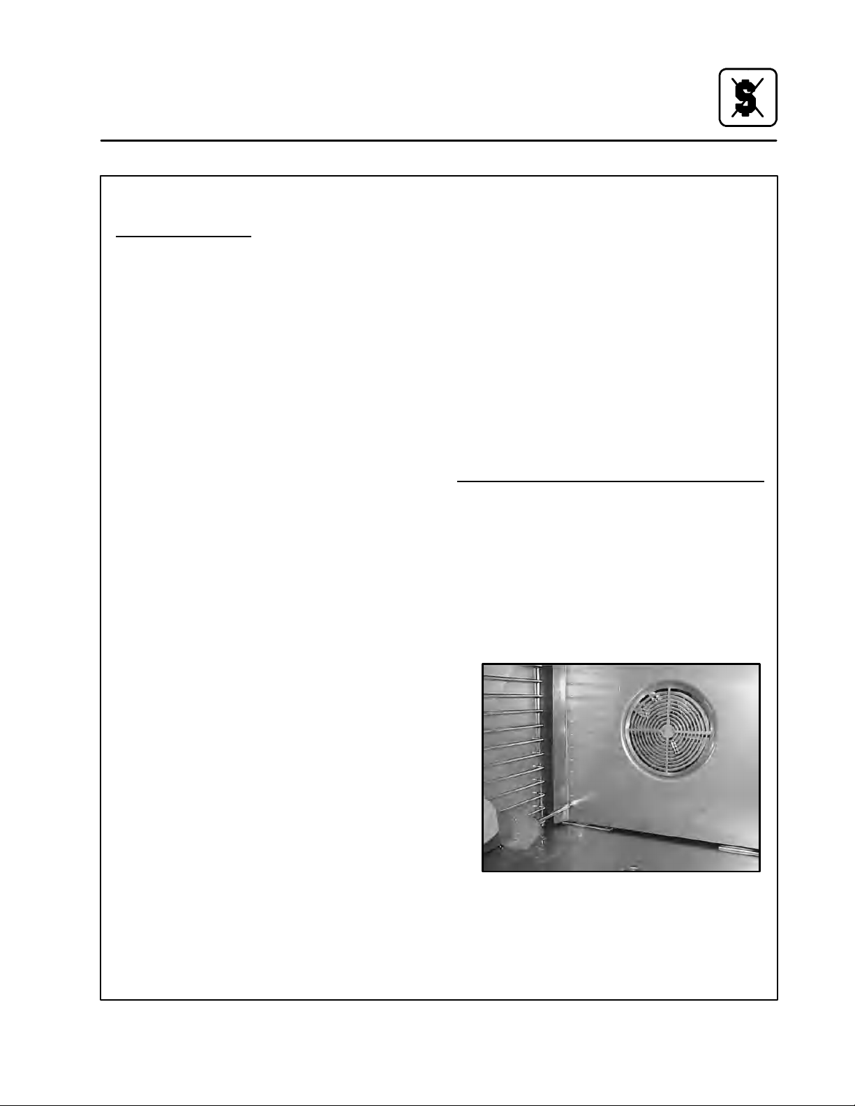
Entretien
Nettoyage et entretien préventif
NETTOYAGEDEL’INTÉRIEUR
Nettoyage
Le nettoyage quotidien du four est essentiel pour
respecter les conditions sanitaires minimales et
éviter les problèmes de fonctionnement. La cavité
en acier inoxydable peut corrodera si le four n’est
pas adéquatement nettoyé. Utilisez un détergent
pour four conjointement au pulvérisateur fourni.
Pour le nettoyage de taches tenaces, laissez agir
plus longtemps le détergent à vaporiser avant de
procéder au rinçage.
1. Laissez refroidir le four à60_C (140_F) ou,
si le four n’était pas utilisé, activez le mode
d’injection de vapeur pendant 3 ou 4 minutes
afin de réchauffer les surfaces de la cavité.
2. Remplissez le pulvérisateur et pompez de l’air
dans le contenant au moyen de la pompe à
pression.
3. Pulvérisez l’intérieur du four avec la solution
de nettoyage. Assurez-vous de vaporiser la
solution de nettoyage à travers la garde de
ventilateur pour couvrir toutes les surfaces.
REMARQUE:Ne pulvérisez jamais de l’eau
4. Laissez le nettoyant agir pendant la période
recommandée par son fabricant.
5. Réglez la minuterie entre 15 et 20 minutes.
6. Réglez le sélecteur de mode sur la position
Steam (vapeur). Ceci permet de ramollir tous
les résidus calcinés.
7. Rincez l’intérieur du four à l’eau (vous pouvez
utiliser un tuyau d’arrosage, mais veillez à
n’arroser que l’intérieur du four). Essuyez l’intérieur après le rinçage.
8. Laportedoitêtregardéeunpeuouverteaprès
le nettoyage. Cela permettra au four de s’aérer et d’accroître la durée de vie utile du joint de
la porte.
Dans le cas d’une cavité en acier inoxydable, enlevez les dépôts d’éclaboussures, d’huile, de grais-
quotidien
dans le four lorsque la température est supérieure à 100_C
(212_F).
se et la décoloration légère avec un bon nettoyeur
industriel non toxique adapté à l’acier inoxydable.
Appliquez le produit lorsque le four est froid et frotteztoujoursdanslesensdugraindumétal.Vous
pouvez nettoyer les grilles, les supports et la roue
du ventilateur à l’intérieur du four même ou les en
retirer et les faire tremper dans une solution d’ammoniaque et d’eau.
REMARQUE:N’EMPLOYEZ PAS des nettoyants
corrosifs non prévus pour le nettoyage des fours sur votre four COMBI.
Nettoyants recommandés:
a.) ECOLAB Greasecutter Plus
b.) CELLO EZ Clean
c.) Diversey-Lever Advance Oven Cleaner
Nettoyage hebdomadaire du four B14 Boilerles
En plus du nettoyage quotidien, il est nécessaire
de nettoyer derrière la garde de ventilateur de ce
four chaque semaine. Ce nettoyage est nécessaire pour le bon fonctionnement du four. Du tartre
s’accumulera sur le ventilateur et les échangeurs
thermiques, ce qui rendra le four moins efficace.
1. Arrêtez le four. Assurez-vousque le four est refroidi à 60_C (140_F).
2. Enlevez les deux vis du côté gauche de la
gardedeventilateur.
Figure 17
s
75
Page 80

Entretien
Nettoyage et entretien préventif
3. Tournez la garde de ventilateur dehors
Figure 18
4. Vaporisez à fond la solution de nettoyage sur
le ventilateur et les tuyaux de l’échangeur
thermique et l’arrière de la murette. Fermez la
portepourlaisserlasolutiondenettoyage
faire son travail.
Indicateur “CLEAN OVEN” du B14
L’indicateur ”CLEAN OVEN” informe l’utilisateur
quelefouraétéenservicependantunepériode
préprogrammée et il est temps de le nettoyer.Il est
nécessaire de complètement nettoyer l’intérieur
en raison des minerais de l’eau qui s’accumuleront. Le propre nettoyage prolongera la vie de
votre four.
Unefoisquel’intérieurdefouraéténettoyél’indicateur ”CLEAN OVEN” doit être remis à zéro. Pour
le remettre à zéro:
1. Placez le four en état de Vapeur (STEAM).
2. Pressez et maintenez le bouton ”STEAM ON
DEMAND” jusqu’à ce que l’indicateur clignote
rapidement.
3. Quand l’indicateur cesse de clignoter laissez
le bouton.
4. Le four a été remis à zéro et va compter le
temps jusqu’au prochain nettoyage.
NETTOYAGEDEL’EXTÉRIEUR
Vous pouvez nettoyer l’extérieur de l’appareil et le
maintenir en bon état au moyen d’une huile légère.
Imbibez un chiffon et frottez l’appareil lorsqu’il est
froid, puis essuyez avec un chiffon propre et sec.
Boilerless
Figure 19
5. Après dix minutes, rincez la solution de nettoyage. Remettez la garde de ventilateur en
position fermée. Insérez les deux vis pour fixer
lagardedeventilateur.
Enlevez et nettoyez la roulette de soufflante tous
les 6 mois.
ATTENTION !!
NE PULVÉRISEZ PAS l’extérieur de l’appa-
reil avec de l’eau et ne le nettoyez pas au
moyen d’un jet d’eau. Nettoyer à l’aide d’un
jet d’eau peut imprégner les chlorures dans
l’acier inoxydable, entraînant la formation
de corrosion.
ENTRETIEN PRÉVENTIF
Les meilleures mesures d’entretien préventif sont
une mise en service initiale du four appropriée et
un programme régulier de nettoyage. Le four-étuveur n’exige aucune lubrification. Communiquez
avec le fabricant, son représentant ou l’entreprise
locale d’entretien des produits Combi de Blodgett
pour effectuer l’entretien et les réparations, le cas
échéant.
76
Page 81

Entretien
Détartrage
REMARQUE:Les procédures ci -dessous s’appli -
quent uniquement aux modèles
BC14E et BC14G.
AVERTISSEMENT !!
Les solutions de détartrage sont dange-
reuses et peuvent causer des brûlures de
la peau et des yeux. Portez des vêtements
et des lunettes de protection pour détartrer l’appareil.
Le détartrage du générateur de vapeur constitue
la procédure de maintenance préventive la plus
importante. Le tartre se dépose à l’intérieur du générateur de vapeur, ce qui réduit son efficacité et
endommagelesystèmedecontrôledeniveau.
AVERTISSEMENT !!
Les problèmes causés par le détartrage
insuffisant ne sont pas couverts par la garantie.
Ce four est fourni avec un voyant de détartrage
pour indiquer le moment où le générateur de vapeur doit être détartré. Le voyant de détartrage clignote lorsque le générateur de vapeur a été utilisé
pendant la période préréglée. Le clignotement du
voyant de détartrage n’empêche pas de faire marcher le four, car vous pouvez utiliser le four normalement lorsque ce voyant clignote. Cela vous permet de choisir le moment opportun pour
commencer le processus de détartrage.
REMARQUE:Pour empêcher les dépôts supplé-
mentaires de tartre, ce four videautomatiquement le générateur de vapeur au bout de 5 heures d’arrêt.
AVERTISSEMENT !!
Lefourdoitêtremisdanslemodedere-
froidissement pendant 1 minute avec la
porteouverte avant de commencer le processusde détartrage.Une fois que le processus a commencé, le four ne peut pas
être utilisé tant qu’il n’est pas terminé. La
durée totale du processus est d’environ
45 minutes.
77
Page 82

Entretien
Détartrage
DÉTARTRAGE SANS L’OPTION DE POMPE DE
DÉTARTRAGE ÉLECTRIQUE
REMARQUE:Les procédures ci -dessous s’appli -
quent uniquement aux modèles
BC14E et BC14G.
REMARQUE:Le voyant de détartrage doit clignoter
pour commencer ce processus.
1. Assurez-vous que le réservoir de solution de
détartrage est rempli avec un agent de détartrage non dilué tel que “Lime Away” de EcoLabsou“LimeOut”deUSChemical.
2. Retirez le bouchon de l’appareil. Connectez
l’extrémité du tuyau de pompe à l’orifice de
détartrage. Voir la Figure 20.
3. Pompez l’agent de détartrage dans l’appareil
en tirant complètement, puis en poussant
vers le bas, la manette de la pompe. Chaque
mouvement vers le haut, puis vers le bas, cor-
respond à un (1) pompage. Utilisez le tableau
ci-dessous.
Modèles
Onces (pompage)
BC14E 16 onces (1 pompage)
BC14G 16 onces (1 pompage)
4. Assurez-vous que la porte est ouverte.
5. Mettez le four dans le mode de refroidisse-
ment. Enfoncez, puis relâchez, le bouton de
vapeur sur demande. Le voyant de détartra-
ge clignote plus rapidement, pour indiquer
cette action.
6. Arrêtez le four.
Le reste de la procédure est automatique. Le
voyant de détartrage reste allumé pendant que le
processus est en cours. Lorsque le processus est
terminé, le voyant de détartrage s’éteint, ce qui indique que le four peut être utilisé normalement.
Vue A
Orifice
de détartrage
Voir la vue A
Figure 20
Pompe de
détartrage
Réservoir de
la solution de
détartrage
Tuyau
Voir la
vue A
78
Page 83
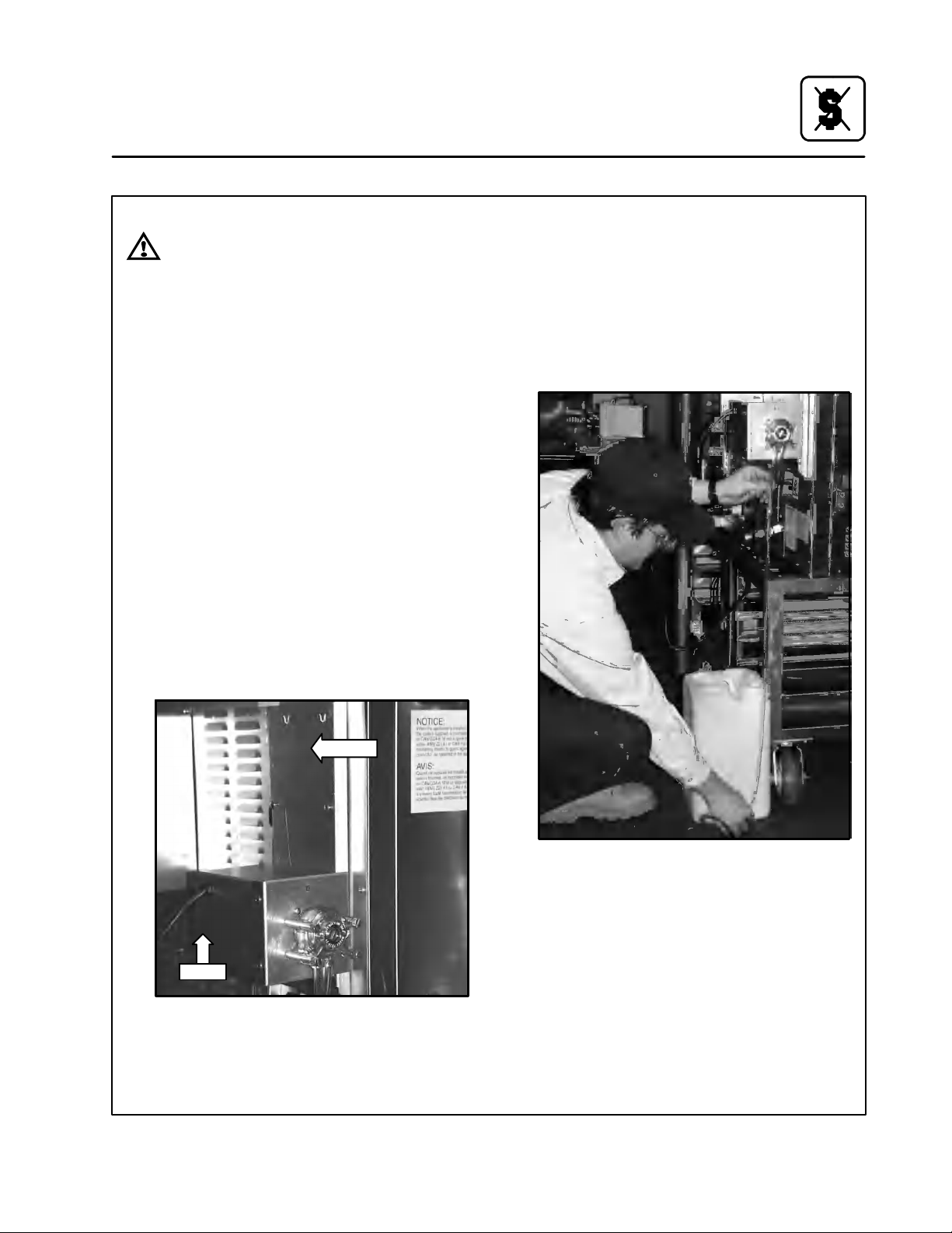
AVERTISSEMENT !!
Si la cavité du four est chaude, il faut mettre
le four dans le mode de refroidissement
pendant 1 minute avec la porte ouverte
avant de commencer le processus de détartrage. Une fois que le processus a commencé, le four ne peut pas être utilisé tant
qu’il n’est pas terminé. La durée totale du
processus est de 45 minutes environ.
INSTALLATION DE LA POMPE DE DÉTARTRAGE
1. Attachez la console pour retenir la pompe au
dosdufour l’aidedequatrevis#10-24etrondelles d’arrêt. S’il s’agit d’une pile de deux
fours, attachez la console sur celui du bas.
2. Attachez la pompe ou les pompes à la conso-
le. Alignez les deux trous rectangulaires dans
le boîtier de la pompe avec les deux pattes sur
la console. Glissez la pompe vers le bas pour
engager les pattes dans les trous. Il peut être
nécessaire de forcer les pattes légèrement
avec un tournevis pour pouvoir les engager
dans le boîtier. Attachez le dessous de chaque
pompe à la console à l’aide de deux vis
#10-24 et rondelles d’arrêt.
Entretien
Détartrage
3. Mettez le réservoir du fluide de carbonatation
àsaplacerelativementàlapompe,aussiprès
que possible, et mesurez la longueur de tuyau
nécessaire pour aller depuis l’entrée de la
pompe jusqu’au fond du réservoir. Coupez
cette longueur du tuyau fourni et attachez-la
àlapompeàl’aided’unraccordàpointeset
un collier de serrage. Au besoin, répétez pour
la deuxième pompe.
Pompe
Console
Figure 22
Figure 21
79
Page 84

Entretien
Détartrage
5. Attachez un bout du tuyau fourni à la sortie de
la pompe à l’aide d’un raccord à pointes et un
collier de serrage. Posez le tuyau jusqu’à l’entrée du four de façon à éviter tout contact avec
les surfaces chaudes, telles que le tuyau
d’évacuation des fumées. Coupez le tuyau à
la longueur qui convient et attachez-le au raccord d’entrée à l’aide d’un collier de serrage.
Au besoin, répétez les actions 3 et 4 pour la
deuxième pompe.
Figure 23
4. Dévissez le bouchon d’entrée à l’arrière du
four. Installez un raccord fileté à pointes dans
l’entrée du four.
Bouchon d’entrée
Porte-fusible
Figure 24
Figure 25
6. Retirez le porte-fusible de la prise de courant
à l’arrière du four ou des fours. Insérez les fusibles fournis. Réinstallez le porte-fusible. Branchez le câble de chaque pompe sur la prise de
courantàl’arrièredechaquefour.Veillez àce
que vous connectiez chaque pompe au
même four auquel son tuyau est connecté.
Câble électrique
80
Figure 26
Page 85

Entretien
Détartrage
7. Remplissez le réservoir à solution avec l’agent
de carbonatation non-dilué, tel que LimeAway produit par Eco-Labs ou Lime-Out de
US Chemical.
8. Pour amorcer le tuyau d’alimentation, mettez
le four en mode COOL DOWN (REFROIDIR),
poussez et retenez le bouton ON DEMAND
STEAM (VAPEUR SUR DEMANDE). Relâchez le bouton une fois que le fluide a passé
par le tuyau et est arrivé à l’arrière du four.
DÉTARTRAGE AVEC L’OPTION DE POMPE DE
DÉTARTRAGE
REMARQUE:Les procédures ci -dessous s’appli -
quent uniquement aux modèles
BC14E et BC14G.
REMARQUE:Le voyant de détartrage doit clignoter
pour pouvoir commencer ce processus.
1. Assurez-vous que le conteneur fournissant
l’agent de détartrage à l’appareil est plein.
2. Assurez-vous que la porte est ouverte.
3. Mettez le four dans le mode de refroidisse-
ment. Enfoncez, puis relâchez, le bouton de
vapeur sur demande.Levoyantdedétartra-
ge reste clignote plus rapidement, pour indiquer cette action.
4. Arrêtez le four.
5. Le reste de la procédure est automatique. Le
voyant de détartrage reste allumé pendant
que le processus est en cours. Lorsque le processus est terminé, le voyant de détartrage
s’éteint, ce qui indique que l’appareil peut être
utilisé normalement.
81
Page 86

Entretien
Détartrage
RÉGLAGE DE L’INTERVALLE DE DÉTARTRAGE
Reportez-vous à la Figure 27 pour déterminer l’intervalle de détartrage approprié à votre appareil.
Cherchez votre lieu et le réglage correspondant
du potentiomètre. Ces valeurs sont génériques, et
doivent être utilisées uniquement comme guide.
Laqualitédel’eauquevousutilisezpeutêtreplus
ou moins calcaire. Ajustez l’intervalle de détartrage en fonction de la qualité de l’eau utilisée.
REMARQUE:Si le four est connecté à un système
de filtration, la dureté de l’eau peut
être réduite. Consultez le fournisseur
du filtre pour obtenir des détails.
Plus de 14 g/gallon
10 à 14 g/gallon Très dure Réglage B
7 à 10 g/gallon Dure Réglage B
3 à 7 g/gallon Modérément dure Réglage C
Moins de 3 g/gallon Légèrement dure Réglage C
Extrêmement dure Réglage A
Figure 27
82
Qualité de l’eau au Canada
La plupart de l’eau canadienne contient 112 mg/litre
(8 g/gallon). Cela situe le Canada dans la catégorie
d’eau dure, et exige l’utilisation du réglage B. Si l’eau
que vous utilisez dépasse 196 mg/litre (14 g/gallon),
le réglage A doit être utilisé.
Page 87

Pour régler l’intervalle de détartrage :
1. Mettez l’appareil hors tension.
2. Retirez les deux vis situées sur le panneau latéral.Glissezlemoduledecommandevers
l’avant. Voir la Figure 28.
3. Amenez le potentiomètre sur le réglage nécessaire. Voir la Figure 29.
4. Remettez en place le module de commande
et les deux vis.
5. Mettez l’appareil sous tension.
Un ordinateur PC peut être branché à la mise sous
tension de l’appareil pour vérifier le réglage du potentiomètre. La ligne d’état “L’intervalle de détartrage est x heure(s) de marche du générateur de
vapeur.” indique 30, 60 ou 90. Reportez-vous à
laFigure 31 de la page 84.
Entretien
Détartrage
Figure 29
Figure 28
Réglage C
Réglage B
Réglage A
TP4
Réglages du potentiomètre
Figure 30
83
Page 88

Entretien
Communications
Le four est équipé d’un port de communication sériel RS-232 situé à l’intérieur du panneau de commande. Un ordinateur portable peut être utilisé
pour visualiser des informations concernant cer-
Software (c) 2002 Blodgett
Blodgett Combi BC---2 Control
ROM Saved Data
===========================
Ve r si o n --- > 3
M o d e l --- > 0
Startup Date---> 25
Startup Month --- > 6
S t a r t u p Ye a r --- > 2
L o w V o l t --- > 3 7
H i g h V o l t --- > 8 0
Steam Time(sec) --- > 16384
S D T i m e ( s e c ) --- > 4 5 7
CNV Time(sec) --- > 239087
Combi Time(sec)---> 71870
Heat DMD events --- > 0378956
Current time --- > 11h : 22m : 10s
Currentdate --->26day6month2year
Total deliming events --- > 3
Steam has been run --- > 21 hour(s) 52 min(s) 8 sec(s) since last deliming.
Next deliming in approximately 3 hour(s) of Steam Generator run time.
Deliming interval is 24 hour(s) of Steam Generator run time.
Deliming History
=====================================
Last address 5 and state 0
Eventno.1on25day5month2year
Eventno.2on23day6month2year
Eventno.3on21day7month2year
Eventno.4on0day0month0year
Eventno.5on0day0month0year
tains paramètres de l’appareil, y compris son historiquede détartrage. Une vue d’écran typique est
montrée ci-dessous.
Explanation of output
Version – Software version.
Model – 1=Gasoven,0=Electricoven.
Startup Date, Month, Year – Date oven was started up.
Low Volt,High Volt – Power supply fluctuations.
Steam Time --- Time in second’s oven has used Steam Mode.
SD Time --- Time in second’s oven has used in On Demand Steam mode.
CNV Time --- Time in second’s oven has used Hot Air Mode.
Combi Time --- Time in second’s oven has used in Combi Mode.
Heat DMD events – Total number of heat demand events.
Current time, Current date --- C u r r e n t d a t e a n d t im e .
Total deliming events --- Total number of times oven has been delimed.
Steam has been run --- > --- How long steam generator has been run since last deliming.
Next deliming.. – Approximately next time steam generator will need a deliming.
Deliming interval ..– Hours the steam generator will run between deliming events.
Deliming History --- The last 52 events will be printed out. If an event has not occurred, a 0 will be
used. Last address and state are used to record the last deliming state in
case of power fail during the process. Normally, state should be 0.
Figure 31
84
Page 89

Pour connecter un ordinateur portable au four
(système d’exploitation Windows de Microsoft)
1. Débranchez l’appareil de la source d’alimentation électrique.
2. Retirez (2) vis et glissez le panneau de commande vers l’avant. Voir la Figure 32.
3. Initialisez l’ordinateur.
4. Raccordez un câble série standardisé au port
sériedel’ordinateurportableetauportsérie
à 9 broches situé sur le carte à circuit imprimé
dans la zone de commande. Voir la Figure 33.
5. Lancez un programme de communication tel
que “Hyperterminal” en sélectionnant Démarr a g e --- --- --- > P r o g r a m m e s --- --- --- > A c c e s s oi r e s --- --- --- >H y p e r t er m in a l --- --- --- >H y p e r Te r m i nal.
6. Entrez un nom pour la connexion et sélectionnez une icône, sélectionnez OK.
7. Cliquez sur “Connecter avec” et sélectionnez
le port COM utilisé par le câble série. Sélectionnez OK.
8. Configurez les paramètres ci-dessous, puis
cliquez sur OK.
a.) Bits par seconde : 9600
b.) Bitsdedonnée:8
c.) Parité : aucune
d.) Bits d’arrêt : 1
e.) Contrôle de débit : Aucun
Pour visualiser les données :
Entretien
Communications
Figure 32
Pour visualiser les données de sortie, l’appareil
doit être débranché de la source d’alimentation
pendant 10 secondes, puis il doit être remis sous
tension. Les données sont alors affichées dans la
fenêtre du terminal. Des données sont aussi affichées pendant le processus de détartrage. Chaque état est affiché à l’écran, accompagné du
compte à rebours du nombre de secondes restant
dans l’état en cours.
Figure 33
85
Page 90

INSERT
WIRING DIAGRAM
HERE
PLACER
SCHÉMA DE CÂBLAGE
ICI
 Loading...