

Blodgett DFG-50, Mark V, DFG-100, KCO-25E, AC-500 Zephaire Installation And Operation Manual
...Page 1

DFG-50, DFG-100, AC-500
Zephaire, Mark V, CTB,
KCO-25E
44 Lakeside Avenue, Burlington, Vermont 05401 USA Telephone (800) 331-5842, (802) 860-3700 Fax: (802)864-0183
BLODGETT OVEN COMPANY
www.blodgett.com
PN 34133 Rev E (6/01)
E 2000 --- G.S. Blodgett Corporation
Page 2

Page 3

Installation and Operation Manual for Export Series Gas and Electric Convection Ovens
Installation 3..........................................................................
Operation 11...........................................................................
Maintenance 20........................................................................
Installations-og Betjeningsvejledning til Gas-og El-konvektorovne Eksportmodeller
Installering 23..........................................................................
Betjening 31...........................................................................
Vedligeholdelse 40......................................................................
Installatie-en Gebruikshandleiding voor Gas en Elektrische Convectieovens Exportserie
Installatie 43...........................................................................
Bediening 51...........................................................................
Onderhoud 60..........................................................................
Manuel d’Installation et d’Utilisation pour la Serie Export des Fours a Convection a Gaz ou
Electriques
Installation 63..........................................................................
Utilisation 71...........................................................................
Entretien 80............................................................................
Handbuch für den Einbau und den Betrieb von Gasbetriebenen und Elektrischen Umluftöfen
der Exportserie
Einbau 83..............................................................................
Betrieb 91.............................................................................
Wartung 100............................................................................
Manuale d’Uso e di Installazione per Forni Termoventilati a Gas ed Elettrici Serie Export
Installazione 103.........................................................................
Funzionamento 111......................................................................
Manutenzione 120.......................................................................
Manual de Instalação e Operação para Fornos de Convecção Elétricos e a Gás da Série Export
Instalação 123...........................................................................
Operação 131...........................................................................
Manutenção 140.........................................................................
ManualdeOperacioneInstalacionparalaSeriedeExportaciondelosHornosdeConveccion
Electricos y a Gas
Instalacion 143..........................................................................
Funcionamiento 151......................................................................
Mantenimiento 160.......................................................................
Handledning för Installation och Drift Exportserien Gas och Elektriska Konvektionsugnar
Installation 163..........................................................................
Drift 171................................................................................
Underhåll 180...........................................................................
Bιβλιο Οδηγιων Εγκαταστασησ και Χειρισµου για τη Σειρα Εξαγοµενων Φουρνων
Ηλεκτρικου και Γκαζιου
Εγκατάσταση 183........................................................................
Χειρισµός 191...........................................................................
Συντήρηση 200..........................................................................
Page 4

Page 5

Installation and Operation Manual
for
Export Series
Gas and Electric Convection Ovens
2
Page 6

Installation
Delivery and Location
DELIVERY AND INSPECTION
All Blodgett ovens are shipped in containers to
prevent damage. Upon delivery of your new oven:
D
Inspect the shipping container for external damage. Any evidence of damage should be noted
on the delivery receipt which must be signed by
the driver.
D
Uncrate the oven and check for internal damage. Carriers will accept claims for concealed
damage if notified within fifteen days of delivery
and the shipping container is retained for inspection.
The Blodgett Oven Company cannot assume
responsibility for loss or damage suffered in
transit. The carrier assumed full responsibility
for del ivery in good order when the shipment
was accepted. We are, however, prepared to
assist you if filing a claim is necessary.
OVEN LOCATION
The well planned and proper placement of your
oven will result in long term operator convenience
and satisfactory performance.
D
Place the oven at least 15.2 cm from the rear
wall and 15.2 cm from the side wall.
D
Place the oven in a properly ventilated area.
D
Place the oven under an exhaust hood, according to Localand NationalInstallationStandards.
D
Position the oven so the supply plug is accessible.
D
Place the oven in an area that is free of drafts.
D
Keepthe oven area free and clear of all combustiblessuch as paper, cardboard, and flammable
liquids and solvents.
D
Do not place the oven on a curb base or seal to
a wall. This will restrict the flow of air and prevent
proper ventilation.
D
For gas models the location must provide adequate clearance for the air opening into the
combustion chamber.
Before making any utility connections to this oven,
check the rating plate to be sure the oven specifications are compatible with the gas (if applicable)
and electrical services supplied for the oven.
3
Page 7
Installation
Oven Assembly
NOTE: This appliance shall be installed in accor-
dance with current regulations and used
only in a well-ventilatedspace. Refer to the
instructions before installing and using
this appliance.
NOTE: Installation must be performed by a quali -
fied installer only.
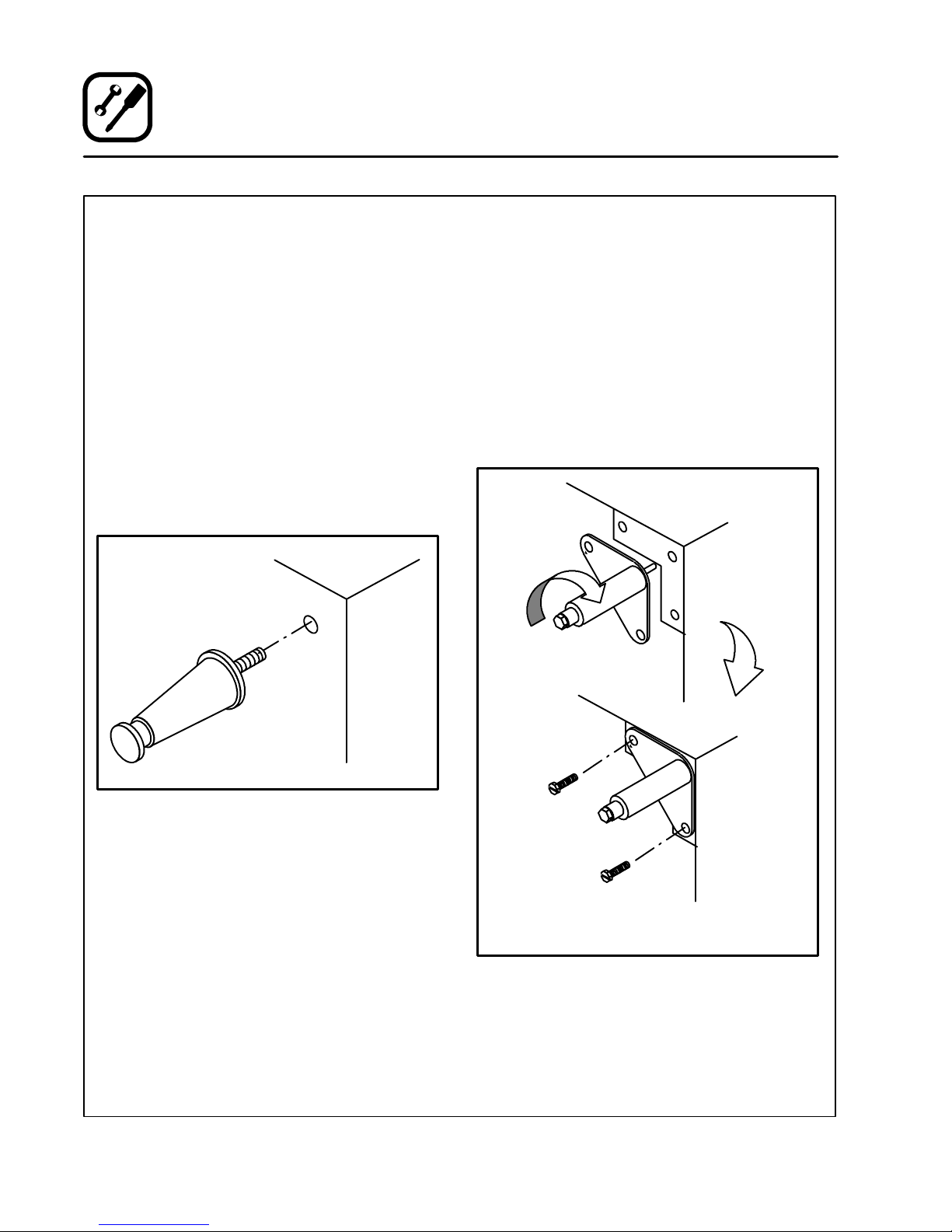
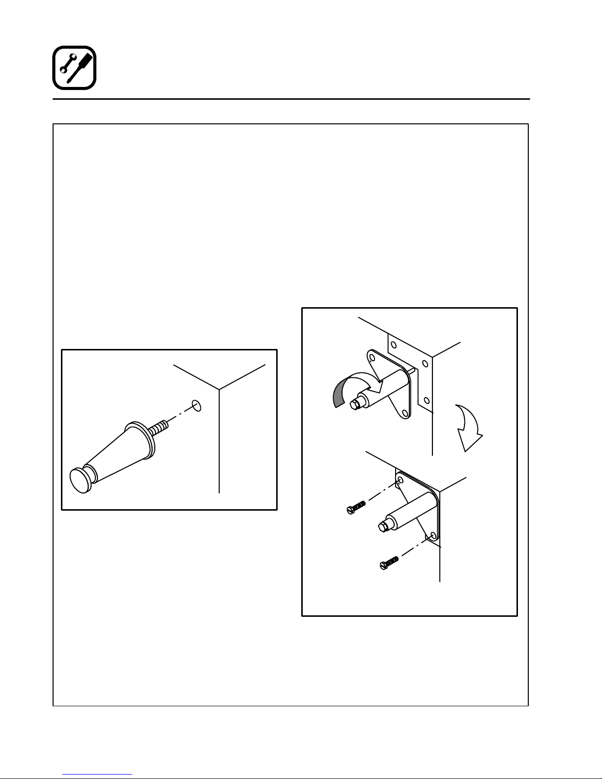
LEG ATTACHMENT
10 cm legs
1. Lay the oven on its back.
2. Screw the legs into the holes in the oven corners. Tighten the hex nut at the top of each leg
3. Tip the oven up on the legs.
4. Turn the adjustable leg feet to level the oven.
15 cm, 18 cm and 64 cm legs
1. Lay the oven on its back.
2. Align the threaded stud in each leg with the
nut inside each bottom corner. Turn the legs
clockwise to tighten.
3. Alignthe holes in each leg plate with the holes
in the oven frame. Secure each leg with two
1/2” bolts.
NOTE: See Caster Installation if applicable.
4. Tip the oven up on the legs.
5. Turn the adjustable leg feet (or casters) to level
the oven.
Figure 1
15 cm Adjustable Legs
Figure 2
4
Page 8

Installation
Oven Assembly
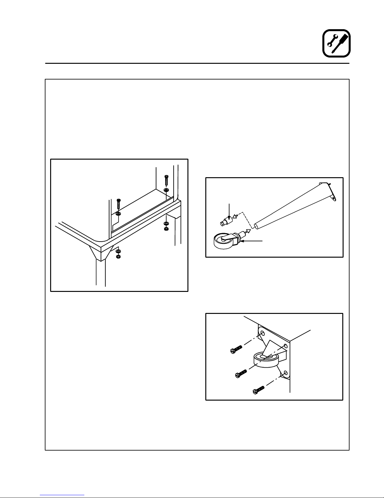
ATTACHMENT TO STAND
1. Set the oven on the stand. Center it to the
frame.
2. Remove the oven’s right side panel.
3. Align t he holes in the oven bottom with the
holes in the stand.
4. Attachwith bolts, washers and nuts as shown.
5. Replace the side panel
CASTER INSTALLATION
NOTE: Install casters with locking devices on the
front. Install non-locking casters on the
rear.
Casters for Single and Double Stacked Ovens
1. Attach the legs.
2. Loosen the lock nut on each adjustable leg
foot. Remove the foot assemblies.
3. Insert one caster into each leg as shown.
Tighten the lock nuts to secure the casters.
Adjustable
Leg Foot
Caster Assembly
64 cm Legs Shown
Figure 4
Figure 3
Low Profile Casters for Double Stacked Ovens
1. Align the three holes in each caster assembly
plate with those in the oven bottom. Attach
with three 1/2” bolts.
Figure 5
5
Page 9
Installation
Oven Assembly
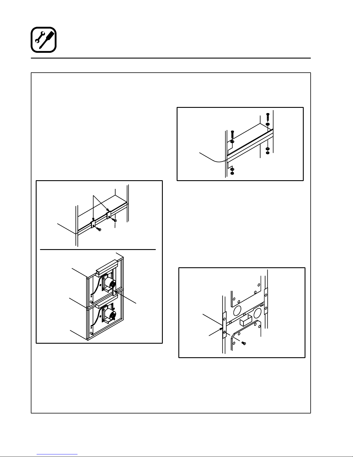
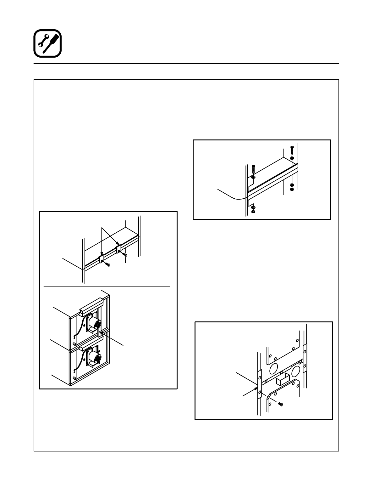
DOUBLE SECTION ASSEMBLY
NOTE: Be sure to remove the single oven flue
boxes prior to attaching the flue connector.
AC-500, DFG-100/200, CTB, Mark V, and
Zephaire E&G
1. Secure the short legs to the bottom sections.
2. Stack t he ovens.
3. Place the clips over the edge of the oven
frames.
4. Bolt the clips together with 3/8” bolts and nuts
provided.
5. Attach the flue connector.
Stacking
Clips
4. Attachwith bolts, washers and nuts as shown.
5. Replace the combustion compartment cover
and side panel.
Figure 7
KCO-25E
1. Secure the short legs to the bottom sections.
2. Stack t he ovens.
3. Remove the bottom left and right screws from
the upper section. Remove the top left a nd
right s crews from the lower section.
4. Attach the two stacking angles. Use the
screws removed.
5. Attach the flue connector.
Figure 6
DFG-50
1. Stack the ovens
2. Remove the combustion compartment cover
and side panel.
3. Align the holes in the front a nd rear corners of
the ovens.
Flue
Connector
Stacking
Angle
Figure 8
6
Page 10

Installation
Oven Assembly
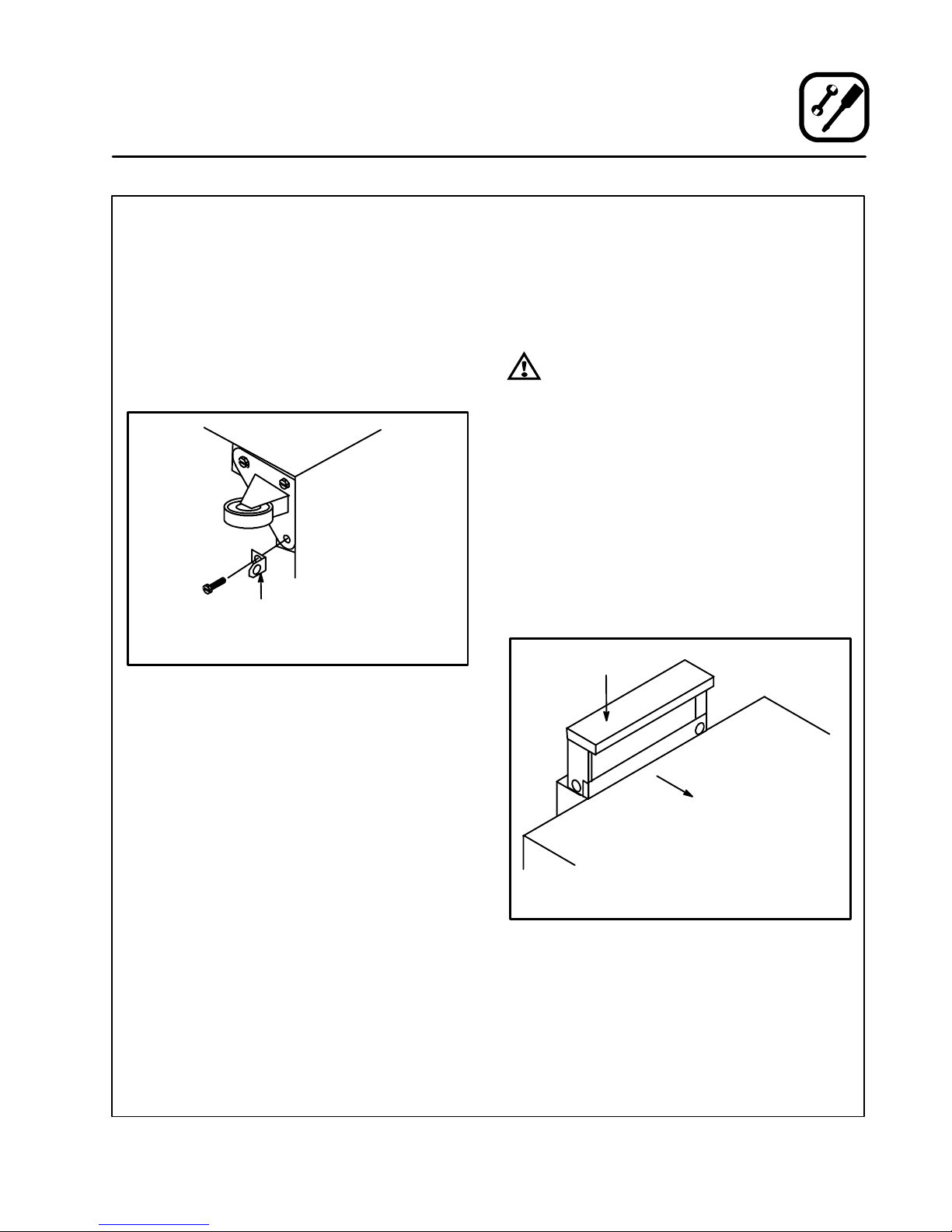
GAS HOSE RESTRAINT ( gas model s)
If the oven is mounted on casters, a commercial
flexible connector with a minimum of 1.9 cm inside
diameter must be used along with a quick connect
device.
1. Mount the supplied bracket to the leg bolt just
below the gas inlet.
2. Attach the clip on restraining cable to the
mounting bracket.
Back of Oven
Restraint Cable
Bracket
Double stacked unit shown.
Figure 9
VENTILATION (gas models)
A mechanically driven, canopy type exhaust hood
is required. The hood should completely cover the
oven with an overhang of at least 15 cm on all
sides not adjacent to a wall. The distance from the
floor to the lower edge of the hood should not exceed 2.1m.
WARNING:
Failure to properly vent the oven can be
hazardous to the health of the operator
and may result in operational problems,
unsatisfactory baking and possible damage to the equipment.
Damage sustained as a direct result of improper ventilation will not be covered by
the manufacturer’s warranty.
Ovens ordered for hood venting are supplied with
a draft diverter. Install the draft diverter as follows:
1. Place the diverter over the flue connector with
the open area facing the front of the oven.
2. Secure with the sheet metal screws provided.
Draft Diverter
Front of
Oven
Full Size Oven Shown
Figure 10
7
Page 11
Installation
Utility Connection
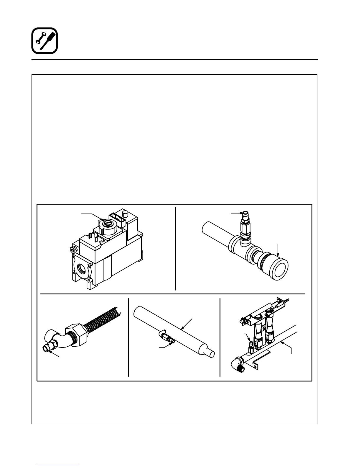
GAS CONNECTION (if applicable)
Connect the oven to the gas line with the proper
type of gas according to Local and National Installation Standards.
Setting Equipment for Other Types of G as
1. Shut off the gas valve and turn off the operating switch.
2. Dismantle the gas block by means of couplings.
3. Dismantle the burner and replace the injectors.
4. Install the burner and gas block.
5. Check for leakage and possible loose electrical connections.
6. Adjust gas pressure if necessary, See figure.
Gas Pressure
Adjustment
INLET PRESSURE TAP
NOTE: Zephaire-G/DFG-50 units only. See figure
for pressure tap location.
1. Removethebluepipecapfromthegasinlet
pipe.
2. Apply thread sealer to the male pipe threads.
3. Thread the inlet pressure tap assembly onto
the gas pipe and tighten.
4. Check for leaks.
Pressure Tap
Gas
Connection
Pressure Tap
DFG-50
Pressure
Tap
DFG-100 and Zephaire-G
Figure 11
8
Back of Oven All Units
Manifold
Pressure
Tap
Manifold
AC-500
Page 12

Installation
G20/G2520/25TotallyScrewedi
n
2,10182x0,3816NaturalGa
s
G20/G2520/25TotallyScrewedi
n
2,1092x0.388NaturalGa
s
G20/G2520/25TotallyScrewedi
n
2,10182x0.3817,6NaturalGa
s
G20/G2520/25TotallyScrewedi
n
1,7516N/A20,5NaturalGas
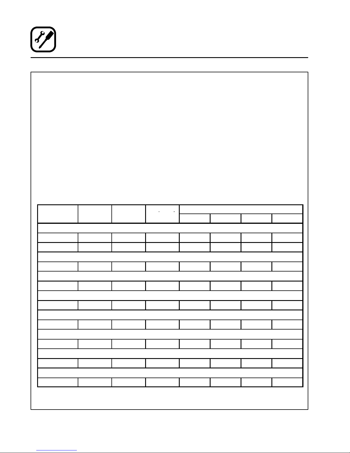
Utility Connection
Type of
Gas
DFG-100-3
G25 25 12 2,60 18 2 x 0,38 16 Natural Gas
G20 20 8 2,60 18 2 x 0,38 16 Natural Gas
G20/G25 20/25 Totally Screwed in 2,10 18 2 x 0,38 16 Natural Gas
G30 30/50 17 1,60 10 2 x 0,20 16 Butane
G31 30/37/50 24 1,60 10 2 x 0,20 16 Propane
DFG-50
G25 25 12 2,50 9 2 x 0.38 8 Natural Gas
G20 20 8 2,50 9 2 x 0.38 8 Natural Gas
G20/G25 20/25 Totally Screwed in 2,10 9 2 x 0.38 8 Natural Gas
G30 30/50 17 1,60 9 2 x 0,20 8Butane
G31 30/37/50 24 1,60 9 2 x 0,20 8Propane
Zephaire-G-L
G25 25 12 2,70 18 2 x 0.38 17,6 Natural Gas
G20 20 8 2,70 18 2 x 0.38 17,6 Natural Gas
G20/G25 20/25 Totally Screwed in 2,10 18 2 x 0.38 17,6 Natural Gas
Inlet
Pressure
mbars
Burner
Pressure
mbars
Pressure Regulator
Pressure Regulator
Pressure Regulator
Injector
Diameter
mm
Air
Opening
mm
Pilot
Injector
mm
Standard
Delivery
Value kW (H
)
i
G30 30/50 17 1,60 10 2 x 0,20 17,6 Butane
G31 30/37/50 24 1,60 10 2 x 0,20 17,6 Propane
AC-500
G25 25 12 2,10 16 N/A 20,5 Natural Gas
G20 20 8 2,10 16 N/A 20,5 Natural Gas
G20/G25 20/25 Totally Screwed in 1,75 16 N/A 20,5 Natural Gas
Pressure Regulator
G30 30/50 17 1,32 16 N/A 20,5 Butane
G31 30/37/50 24 1,32 16 N/A 20,5 Propane
9
Page 13
Installation
V
q
y
Utility Connection
ELECTRICAL CONNECTION
NOTE: Electrical connection must be performed
by a qualified installer only.
NOTE: The electrical connection must comply
with National and Local codes.
A strain relief for the supply cord is required. The
installer must provide a supply cord bushing that
meets all Local and National Installation Standards.
For Gas Models:
NOTE: Gas models havea phase sensitiveburner
control unit. If the phase and neutral are
switched the control locks out.
Connect phase + neutral + ground.
Frequency
KW/Section
CTB/CTBR
5,6 400 3N 50 9 8 8 1
8,0 400 3N 50 13 11 11 2
oltage Phase
(Hz)
For Electric Models:
Connect the oven to a separate group with rigid
connectionand circuit breaker.The circuit breaker
should disconnect all poles, including neutral with
a contact separation of at least 3 mm.
For 1 Phase --- Connect phase + neutral +
ground.
For 3 Phase --- Connect L1 + L2 + L3 + neutral +
ground.
INITIAL STARTUP
1. Set the THERMOSTAT to 260_Candoperate
for 2 hours prior to loading product. This procedure produces smoke.
2. Clean the oven after the initial burn-in process.
See page 20 for proper cleaning instructions.
Max Load
L1 L2 L3 N
KCO-25E
3,0 230 1N 50 13 --- --- 13
Mark V-III
11,0 400 3N 50 18 15 15 3
Zephaire-E
11,0 400 3N 50 18 15 15 3
DFG-100-3
0,7 230 1N 50 3 --- --- 3
DFG-50
0,7 230 1N 50 3 --- --- 3
Zephaire-G-L
0,7 230 1N 50 3 --- --- 3
AC-500
1,3 230 1N 50 6 --- --- 6
10
Page 14
2
Gas Models
Only
3
4
5
6
7
8
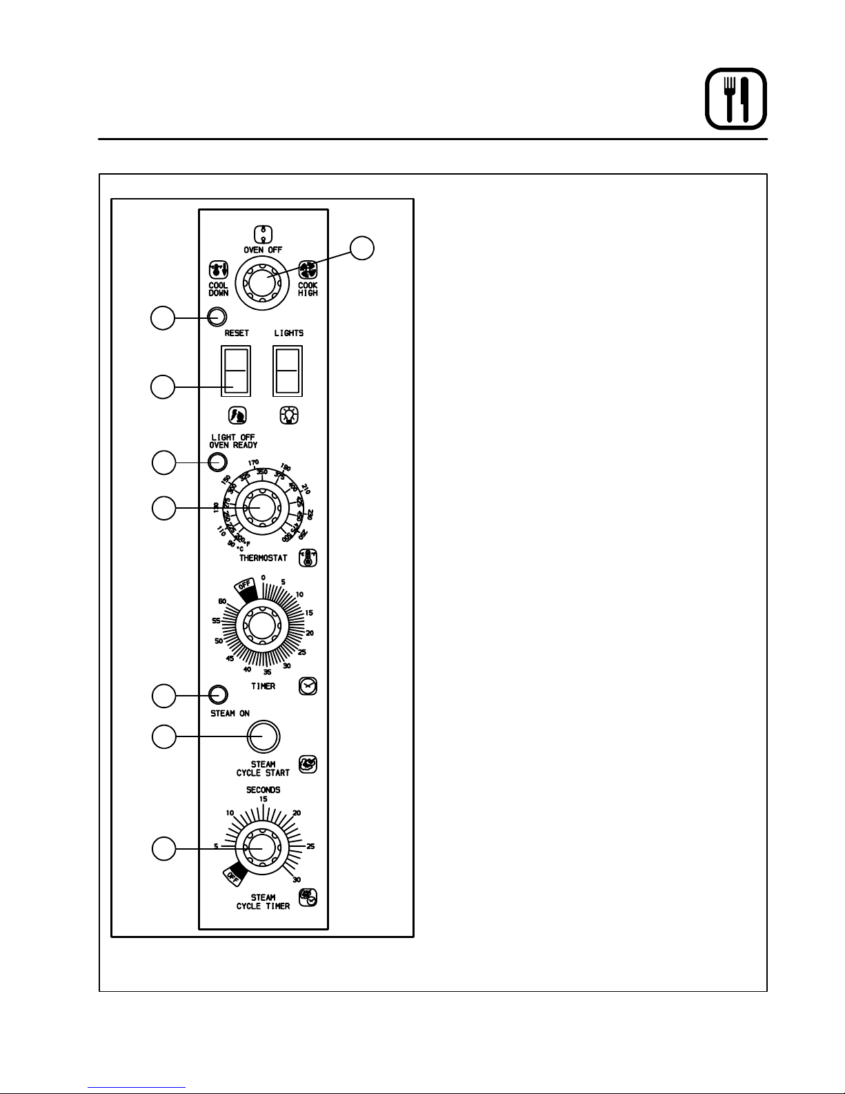
Operation
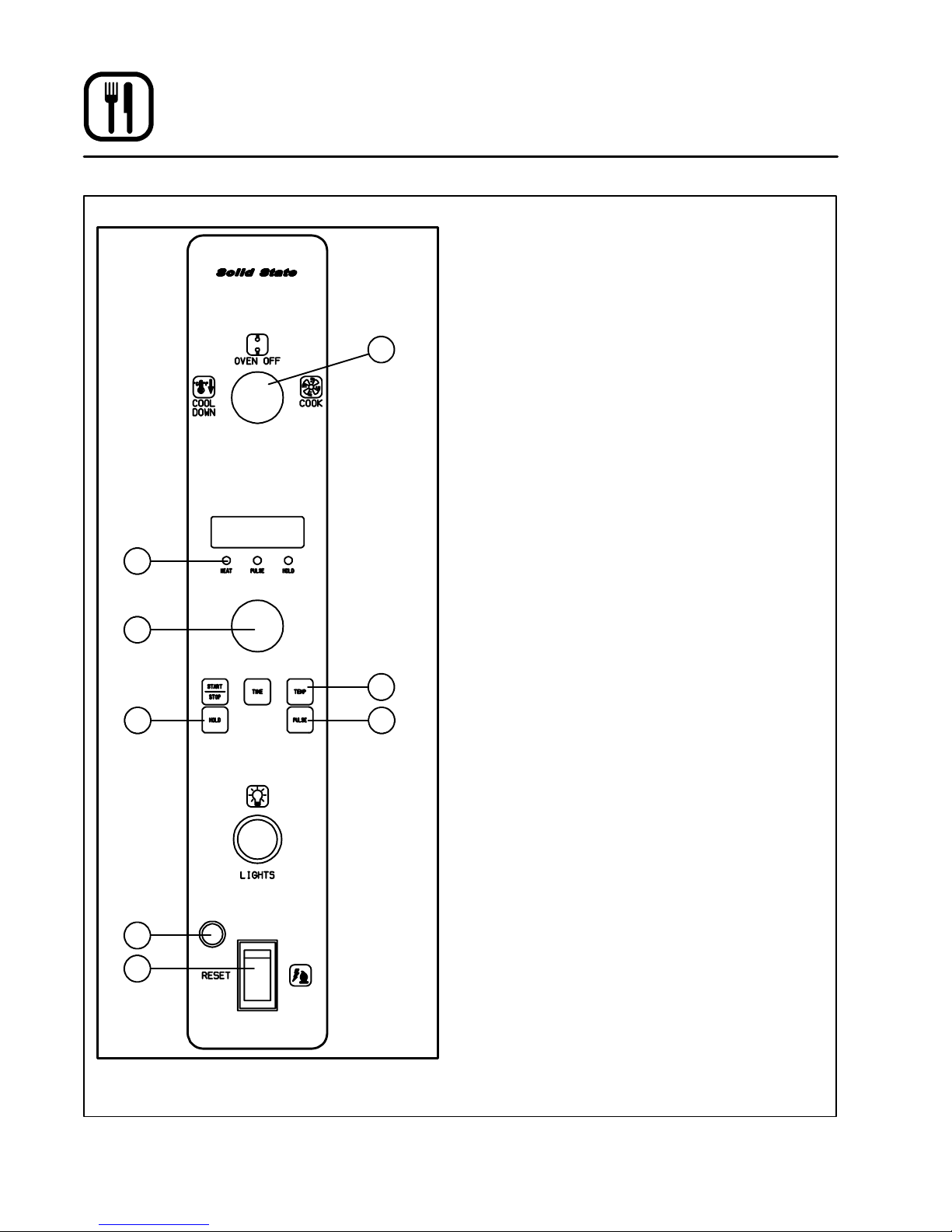
Solid State Controls
OPERATION
NOTE: Operationis restrictedto qualifiedperson-
1
1. Turn on the gas valve. (Gas models only.)
2. Close the oven door.
3. Turn the SELECTOR Switch (1) to the desired
4. Set THERMOSTAT (5) to the desired tempera-
NOTE: If the oven will not start after several at-
For the HUMIDAIRE control option:
1. When steam is desired, set the STEAM
2. Momentarily press and release the STEAM
Cool Down
1. Open oven door.
2. Turn the SELECTOR Switch (1) to COOL
Shut Down
1. Turn the SELECTOR Switch (1) to OFF.
2. Shut off the gas valve. (Gas models only.)
nel.
cook position.
The fan will start to turn and the temperature
controlwillgoon.
ture.
The burner will ignite or the elements willcome
on. The OVEN READY light (4) on the control
panelwillilluminate.
For gas models if in starting, the burner does
not ignite within a few seconds, the RESET
alarm light (2) will go on. Press the RESET
switch (3) to restart the burner.
The LIGHT OFF OVEN READY light (4) will go
out when the oven has reached temperature.
tempts contact a qualified installer.
CYCLE TIMER (8) to the required injection
time.
CYCLE START button (7). The STEAM indicator (6) will light as water is injected into the
baking compartment.
DOWN.
Figure 12
11
Page 15
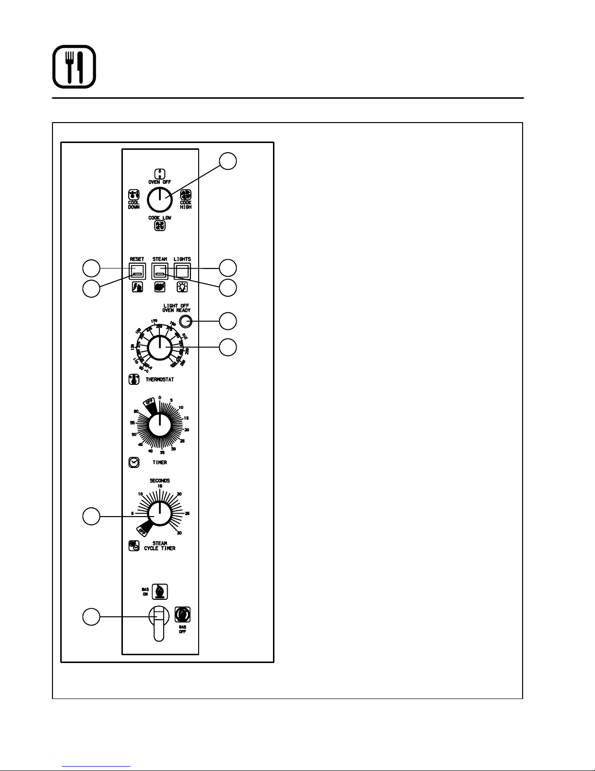
Operation
AC-500 Solid State Controls
2
3
8
OPERATION
1
4
5
6
7
NOTE: Operationis restrictedto qualifiedperson-
nel.
1. Turn on the gas valve (9).
2. Close the oven door.
3. Turn the SELECTOR Switch (1) to the desired
cook position.
The fan will start to turn and the temperature
controlwillgoon.
4. Set THERMOSTAT (7) to the desired temperature.
Theelementswillcomeon.TheOVENREADY
light (6) on the control panel will illuminate.
If in starting, the burner does not ignite within
a few seconds, the RESET alarm light (3) will
go on. Press the RESET switch (2) to restart
the burner.
The LIGHT OFF OVEN READY light (6) will go
out when the oven has reached temperature.
NOTE: If the oven will not start after several at-
tempts contact a qualified installer.
For the HUMIDAIRE control option:
1. When steam is desired, set the STEAM
CYCLE TIMER (8) to the required injection
time.
2. Momentarily press and release the STEAM
CYCLE START button (4). The STEAM indicator (5) will light as water is injected into the
baking compartment.
Shut Down
1. Turn the SELECTOR Switch (1) to OFF.
2. Shut off the gas valve (9).
9
Figure 13
12
Page 16
1
2
3
4
Gas
Models
Only
5
ON
OFF
ON
OFF
MAN
AUTO
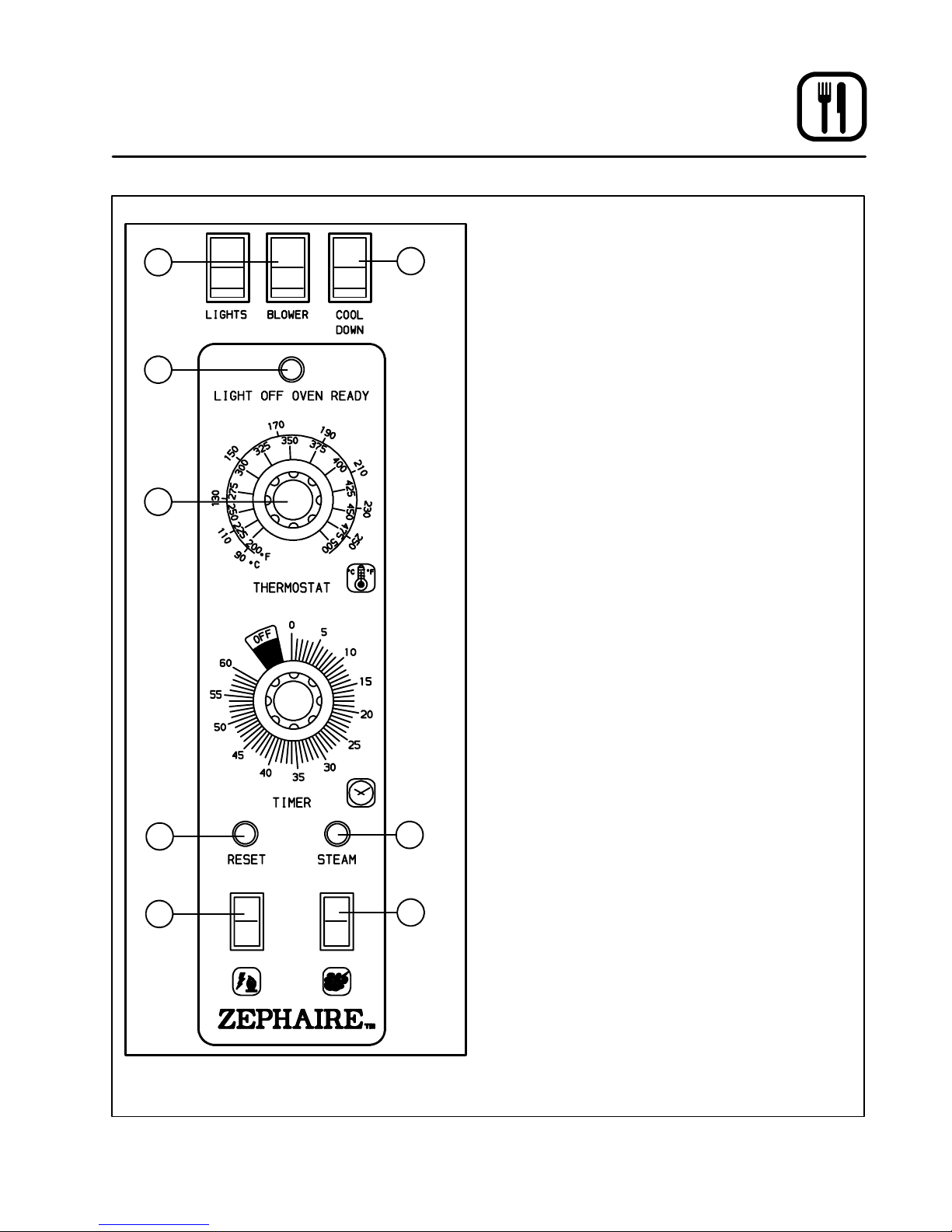
Operation
Zephaire Controls
OPERATION
8
6
7
NOTE: Operationis restrictedto qualifiedperson-
nel.
1. Turn on the gas valve. (Gas models only.)
2. Close the oven door.
3. Turn the BLOWER Switch (1) on the front panel
to ON. Set the COOL DOWN Switch (8) to
AUTO.
The fan will start to turn and the temperature
controlwillgoon.
4. Set THERMOSTAT (3) to the desired tempera-
ture.
The burner will ignite or the elements willcome
on. The OVEN READY light (2) on the control
panelwillilluminate.
For gas models if in starting, the burner does
not ignite within a few seconds, the RESET
alarm light (4) will go on. Press the RESET
switch (5) to restart the burner.
The LIGHT OFF OVEN READY light (2) will go
out when the oven has reached temperature.
NOTE: If the oven will not start after several at-
tempts contact a qualified installer.
For the HUMIDAIRE control option:
1. Momentarily press and release the STEAM
CYCLE START button (7). The STEAM indicator (6) will light as water is injected into the
baking compartment.
Cool Down
1. Open oven door
2. Set the BLOWER Switch to ON.
3. Set COOL DOWN Switch (8) to MANUAL.
Shut Down
1. Turn the BLOWER Switch (1) to OFF.
2. Turn the THERMOSTAT (3) to OFF.
3. Shut off the gas valve. (Gas models only.)
Figure 14
13
Page 17
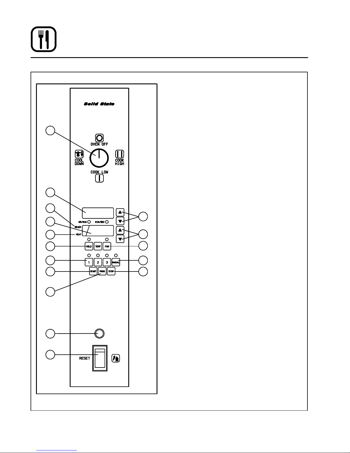
Operation
CH-Pro3 (Solid State Programmable Digital Control)
NOTE: Operationis restrictedto qualifiedperson-
nel.
OPERATION
Oven Startup:
1. Turn the SELECTOR SWITCH (1) to the de-
1
2
sired cook position. The burners ignite or the
elements come on. The HEAT INDICATOR (7)
lights.
On gas models, if the burner does not ignite
within a few seconds, the RESET ALARM
LIGHT(15)comeson.PresstheRESET
SWITCH (16) to restart the burner.
NOTE: If the oven will not start after several at-
tempts contact a qualified installer.
Manual Operation:
4
5
7
8
10
12
13
15
16
Gas Models
Only
Figure 15
3
6
9
11
14
NOTE: Press the arrow keys to change the cook
time and temperature at any point during
manual operation.
1. Press the MANUAL PRODUCT KE Y (11). The
manual and fan key LEDs light.
2. Press the TIME ARROW KEYS (3) to enter the
cook time.
For Cook with Pulse --- P r e s s th e FA N K E Y
(9). Use the TIME ARROW KEYS (3) to enter
the pulse time. The fan key LED flashes.
3. Press the TEMPERATURE ARROW KEYS (6)
to enter the cook temperature.
4. For Cook and Hold --- Press and hold the
HOLDKEY (8). At the same time, use the TEMPERATURE ARROW KEYS (6) to enter the
hold temperature. The hold key LED lights.
5. The READY INDICATOR (4) lights when the
oven has reached the cook temperature.
6. Press the START KEY (12). The TIME DISPLAY
(2) counts down. The manual key LED flashes.
7. When the cook time expires the LEDs and displays flash and an alarm sounds. Press the
STOP KEY (14) to silence the alarm.
NOTE: In Cook and Hold the alarm self can-
cels. The oven cools to the hold temperature. The time display counts up.
Press the HOLD KEY (8) to turn off hold
mode.
14
Page 18

Operation
CH-Pro3 (Solid State Programmable Digital Control)
Product Key Operation:
1. Press the desired PRODUCT KEY (10). The
applicable LEDs light.
2. The READY INDICATOR (4) lights when the
oven has reached the cook temperature.
3. Press the START KEY (12). The TIME DISPLAY
(2) counts down. The product key LED flashes.
NOTE: InCookwithPulsethefanLEDflashes.
4. When the cook or pulse time expires the applicable LEDs and both displays flash and an audible alarm sounds.
5. Press the STOP KEY (14) to silence the alarm.
NOTE: In Cook and Hold the alarm self can-
cels. The oven cools to the hold temperature. The time display counts up.
Press the HOLD KEY (8) to turn off hold
mode.
Oven Shut Down:
1. T urn the SELECTOR SWITCH (1) to OVEN OFF.
PROGRAMMING THE PRODUCT KEYS
NOTE: This procedure is also used to program
the default settings for the manual key.
1. Turn the SELECTOR SWITCH (1) to the desired cook position.
2. Press the desired PRODUCT KEY (10). The
product and fan key LEDs light.
3. Press a nd hold the PROGRAM KEY (13) for
approximately five seconds until the product
key LED flashes.
4. Press the TIME ARROW KEYS (3) to enter the
cook time.
For Cook with Pulse --- P r e s s th e FA N K E Y
(9). Use the TIME ARROW KEYS (3) to enter
the pulse time.
5. Press the TEMPERATURE ARROW KEYS (6)
to enter the cook temperature.
6. For Cook and Hold --- Press and hold the
HOLD KEY (8). At the same time use the TEMPERATURE ARROW KEYS (6) to enter the
hold temperature.
7. Pressthe PROGRAM KEY (13) to save the program settings.
15
Page 19
Operation
Solid State Digital Control
2
3
OPERATION
NOTE: Operationis restrictedto qualifiedperson-
nel.
1. Turn on the gas valve. (Gas models only.)
2. Close the oven door.
1
4
65
3. Turn the SELECTOR Switch (1) to the desired
cook position.
The fan will start to turn and the temperature
controlwillgoon.
4. Press the TEMP key (4) and rotate the dial to
enter the desired temperature.
The burner will ignite or the elements willcome
on. The HEAT light (2) on the control panel will
illuminate.
For gas models if in starting, the burner does
not ignite within a few seconds, the RESET
alarm light (7) will go on. Press the RESET
switch (8) to restart the burner.
TheHEATlight(2)willgooutwhentheoven
has reached temperature.
NOTE: If the oven will not start after several at-
tempts contact a qualified installer.
For Cook with Pulse:
NOTE: Set the pulse time before loading the prod-
uct.
1. Press the PULSE KEY (6).
2. Rotate the DIAL (3) to enter the pulse time.
Pulsetimeisaportionofthecooktime.
For Cook and Hold:
7
8
Gas Models
Only
Figure 16
NOTE: Settheholdtimebeforeloadingtheprod-
uct.
1. Press the HOLD KEY (5).
2. Rotate the DIAL (3) to enter the hold time.
Cool Down
1. Open oven door.
2. Turn the SELECTOR Switch (1) to COOL
DOWN.
Shut Down
1. Turn the SELECTOR Switch (1) to OFF.
2. Shut off the gas valve. (Gas models only.)
16
Page 20
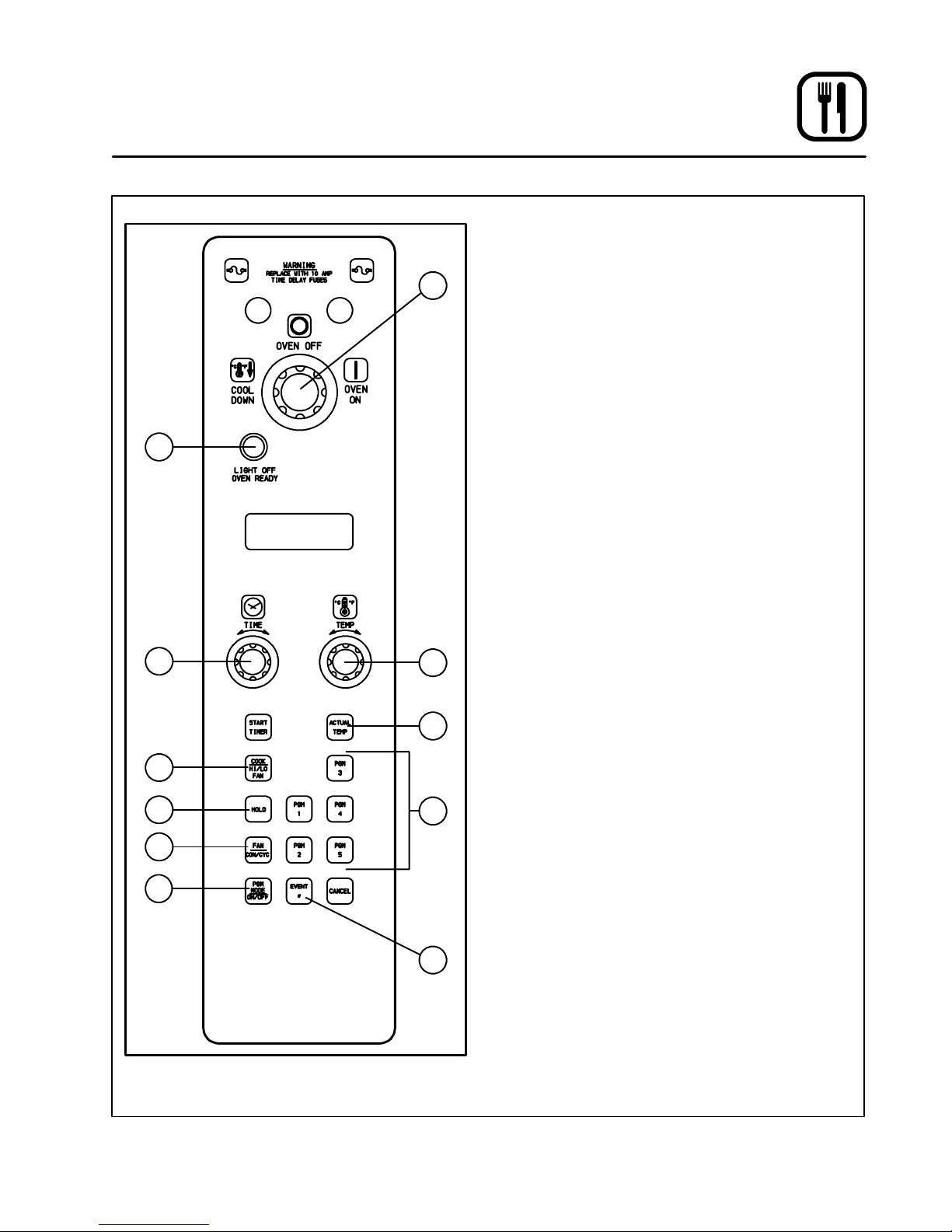
Operation
Intelliplus
OPERATION
NOTE: Operationis restrictedto qualifiedperson-
1
NOTE: Electric models only.
1. Close the oven door.
2. Turn the SELECTOR Switch (1) to OVEN ON.
3. Rotate the TEMPERATURE DIAL (4) to the de-
4. Press the COOK HI/LO FAN key (6) to select
2
5. Press the FAN CON/CYC k ey (9) to select the
6. To display the temperature within the oven,
NOTE: If the oven will not start after several at-
For Cook and Hold:
nel.
sired cooking temperature.
The LIGHT OFF OVEN READY (2) will light.
the fan speed.
fan mode.
press and hold the ACTUAL TEMP key (5).
The oven has reached temperature when the
LIGHT OFF OVEN READY (2) light goes out.
tempts contact a qualified installer.
10
3
6
7
9
Figure 17
4
5
8
11
NOTE: Settheholdtimebeforeloadingtheprod-
uct.
1. Press the HOLD KEY (7).
2. Rotate the DIAL (3) to enter the hold time.
Chain Event Programming:
1. Press PGM MODE ON/OFF (10).
2. Press the desired PGM# (8) key to program.
3. Set the temperature, fan speed, fan mode and
cook time. See above.
4. Press the EV ENT # (11) key to advance to the
next event.
5. When all events have been programmed
press PGM MODE ON/OFF (10).
To use programming:
1. Load the product.
2. Press desired PGM # (8) key.
Shut Down
1. Turn the SELECTOR SWITCH (1) to OVEN
OFF.
17
Page 21
Operation
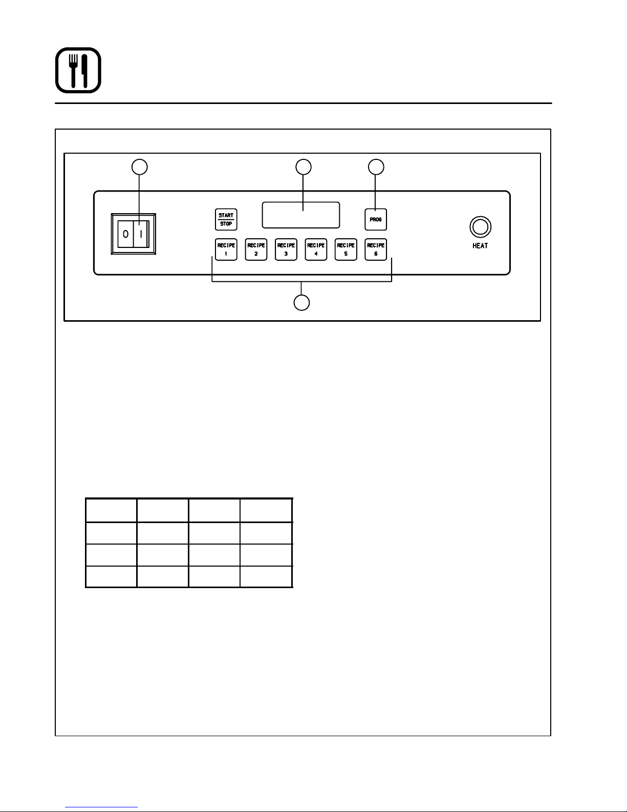
KCO-25E Solid Stage Digital
1 2 3
4
Figure 18
OPERATION
NOTE: Operationis restrictedto qualifiedperson-
nel.
1. Toggle the POWER SWITCH (1) to the ON
position.
2. Select one of the programmed PRODUCT
KEYS (4).
NOTE: Press once for one pan, twice for two
pans, etc.
The product keys have been programmed at
the factory as follows:
Recipe
1 149_C 4 191_C
2 163_C 5 205_C
3 177_C 6 219_C
3. When the DISPLAY (2) flashes PROD and 1
the unit is at the programmed temperature.
NOTE: If the oven will not start after several at-
tempts contact a qualified installer.
Shut Down
1. Toggle the POWER SWITCH (1) to the OFF
position.
Tem p. Recipe Tem p
PROGRAMMING
1. Press the PROGRAM (3) key.
2. When the display reads CODE,usetheproduct keys to enter 1 1 1 1. Press the PROGRAM
(3) key.
3. Press the desired product key. The display
reads TE # and the current cook temperature.
Use the product keys to enter the new cook
temperature. Press t he PROGRAM (3) key.
4. The display reads TI # and the current cook
time for one pan. Use the product keys to enter the new cook time. Press the PROGRAM
(3) key.
5. Repeatstep 4 for up to three pans. The display
reads PROG.
6. Press the PROGRAM (3) key to exit program ming.
18
Page 22
Operation
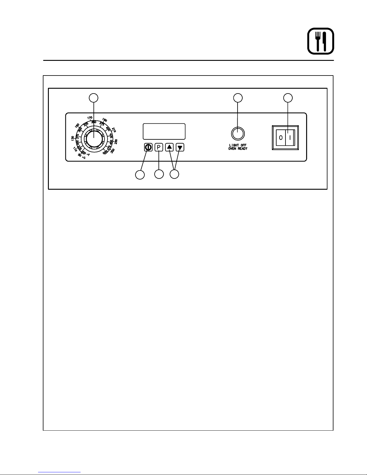
KCO-25E Infinite Control
31 2
6
OPERATION
NOTE: Operationis restrictedto qualifiedperson-
nel.
1. Toggle the POWER SWITCH (3) to the ON
position.
2. Set the THERMOSTAT (1) to the desired setting. The oven has reached temperature when
the LIGHT OFF OVEN READY (2) light goes
out.
NOTE: If the oven will not start after several at-
tempts contact a qualified installer.
Using the Timer (8 Presets)
1. Press UP and D OWN ARROW (5) keys to
scroll to desired preset.
2. Press the START/STOP key (6) to start timer
countdown.
Shut Down
1. Toggle the POWER SWITCH (3) to the OFF
position.
4 5
Figure 19
TIMER PROGRAMMING:
1. Press and hold the TIMER PROGRAM KEY (4).
2. Press UP or DOWN ARROW (5) keys t o scroll
to the desired cook time.
3. Pressthe TIMER PROGRAM KEY (4) to exitthe
program mode.
19
Page 23
Maintenance
Cleaning
WARNING!!
DO NOT spray the oven with a water jet.
DAILY
1. Saturate a cloth w ith light oil. W ipe the oven
exterior when it is cold. Dry the oven with a
clean cloth.
2. Clean stainless surfaces with a non-toxic industrial stainless steel cleaner. Apply the
cleaner when the oven is cold, and always rub
with the grain of the metal.
3. Clean the porcelain interior with a non-toxicin dustrial porcelain cleaner.
WEEKLY
1. Remove the racks and rack support. Soak
them in a solution of ammonia and water.
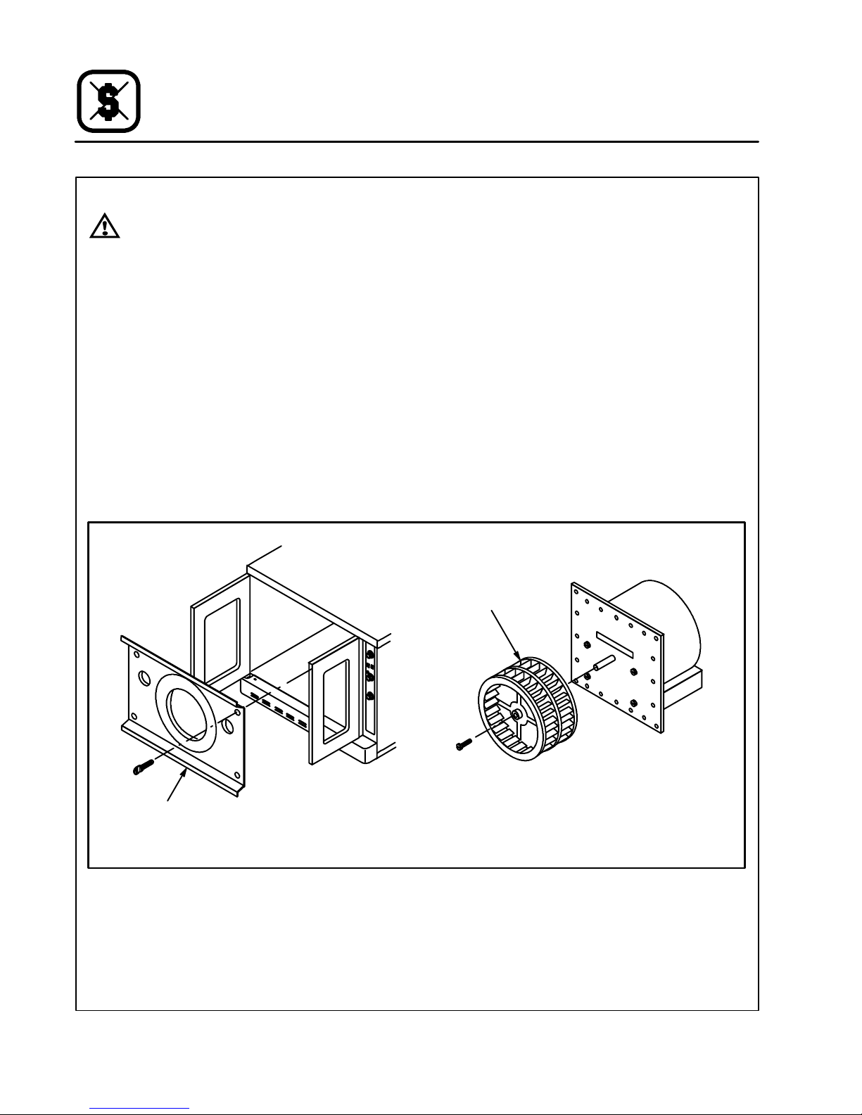
EVERY 12 MONTHS
For all oven models:
1. Check the main electrical connection.
2. Remove the blower wheel. Soak in a solution
of ammonia and water.
For gas models only:
1. Check the venting system for possible deterioration resulting from moisture and corrosive
flue products.
2. Check and adjust the gas setting.
Blower Wheel
Cover
Blower Wheel
DFG-100-3 Shown
Figure 20
20
Page 24
Maintenance
Replacement of Parts
ELECTRICAL COMPONENTS
1. Turn off the main electrical connection to the
oven.
2. Remove the components from the panel and
set the wiring aside.
3. Reinstall the components.
GAS CONTROL COMBINATION
NOTE: Gas models only.
1. Shut off the gas and turn off the power to the
oven.
2. Remove the electrical connection.
3. Remove the gas connection in front of and behind the control combination.
4. Remove the pilot line, replace, reinstall, and
adjust. Check for gas leaks.
REMOVAL OF BURNER
NOTE: Gas models only.
1. Shut off the gas and turn off the power.
2. Remove the combustion cover.
3. Remove the gas connection, etc.
4. Remove the screw s from the burner mounting
bracket.
5. Remove the burner from t he combustion
chamber.
6. Replace pilot burner if necessary. Install the
burner.
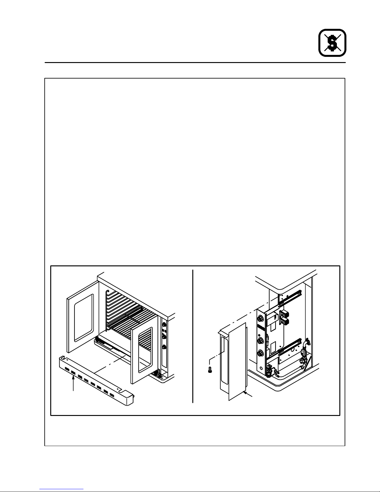
CONTROL COMPARTMENT COMPONENTS
1. Switch power off.
2. Remove the combustion cover.
3. Remove the control compartment cover.
4. Slide the control panel out.
5. Replace and repair the respective component.
6. Install the panel, the control compartment
cover and combustion cover.
Combustion
Cover
Control Cover
DFG-100-3 Shown
Figure 21
21
Page 25

Installations-og Betjeningsvejledning
til Gas-og El-konvektorovne
Eksportmodeller
22
Page 26

Installering
Levering og Placering
LEVERING OG INSPICERING
Alle Blodgett ovne er emballeret i kasse til forsendelse. Ved modtagelsen skal man:
D
Inspicere kassen med ovnen for ydre skader;
dersom skade konstateres, skal dette noteres
på fragtbrevet, der skal underskrives af fragtmanden.
D
Tag ovnen ud af emballagen, og se den efter for
intern skade. Fragtlinien anerkender anmeldelse af intern forsendelsesskade, hvis man gør
det inden for 15 dage efter modtagelsen og
gemmer emballagen til inspektion.
Blodgett Oven Company påtager sig intet ansvar for tab eller skade under forsendelsen.
Fragtlinien har ansvar for levering i god stand,
da forsendelsen blev modtaget. Men vi kan assistere, dersom der er behov for at indgive
klage.
OVNENS PLACERING
Ovnen vil få let betjening og tilfredsstillende ydelse
i det lange løb ved velgennemtænkt og korrekt
placering.
D
Ovnen skal anbringes således, at der er mindst
15,2 cm til væggen bag den og ligeledes 15,2
cm til vægge på siderne.
D
Ovnen skal anbringes et velventileret sted.
D
Ovnen skal anbringes under en emhætte iht.
gældende lokal--- og landsregulativ.
D
Anbring ovnen sådan, at den ikke blokerer stikkontakten.
D
Placér ovnen, hvor det ikke trækker.
D
Hold området omkring ovnen fri for brandfarlige
materialer, såsom papir og pap, og for væsker
og opløsningsmidler.
D
Ovnen må ikke placeres på et lukket fodstykke
eller slutte tæt op af en væg, da lufttilgangen
derved spærres og forhindrer passende ventilering.
D
Gasovne skal placeres, så der er tilstrækkelig
frit til luftindtaget til brænderen.
Man skal selvfølgelig sikre sig, at ovnens specifikationer på mærkeskiltet svarer til henholdsvis
de n t y p e g a s --- e l l e r e l --- f o r s y n i n g , m a n h a r, i n d e n
den tilsluttes ledningerne.
23
Page 27
Installering
Ovnens Samling
NOTE: Denne ovn skal installeres i henhold til
gældende regulativer og må kun benyttes
i velventilerede rum. Læs installations--og betjeningsvejledningen, inden oven
installeres og tages i brug.
NOTE: Ovne skal installeres af en autoriseret
installatør.
MONTERING AF BEN
10 cm ben
1. Læg ovnen ned på bagsiden.
2. Skru benene i gevindhullerne i hjørnerne af
ovnen, og spænd møtrikken oven i benene.
3. Rejs ovnen op på benene.
4. Justér tæerne på benene, så ovnen står i vater.
15cm,18cmog64cmben
1. Læg ovnen om på bagsiden.
2. Styr gevindstudsene i benene til møtrikkerne
i stelhjørnerne, og spænd dem i.
3. Ret hullerne i toppladerne på benene og ovnrammen ind med hinanden, og spænd benene på med to 1/2” bolte.
NOTE: Der henvises endvidere til afsnittet
Monteringaf hjul, dersom man agter at
bruge dem.
4. Rejs oven op på benene.
5. Justér tæerne (eller hjulene) på benene, så
ovnen står i vater.
Figure 1
15 cm justerbare ben
Figure 2
24
Page 28
Installering
Ovnens Samling
MONTERING PÅ STATIV
1. Anbring ovnen midt på stativet.
2. Afmontér ovnpanelet i højre side.
3. Ret hullerne i bunden af ovnen og stativet ind
med hinanden.
4. Spænd ovnen på stativet med bolte, skiver og
møtrikker, som vist på Figure 3.
5. Sæt sidepanelet på igen.
MONTERING AF HJUL
NOTE: Montérhjulenemedlåsforpå,oghjul
uden lås bag på ovnen.
Montering af svirvelhjul på enkelt-- og do bbeltovne
1. Montér benene.
2. Løsn låsemøtrikken på de justerbare tæer, og
skru tæerne af.
3. Sæt et svirvelhjul på hver ben, som vist på fig.
4, og spænd dem fast med låsemøtrikkerne.
Justerbar tå
Svirvelhjul
Illustrationen viser 64 cm bentype
Figure 4
Figure 3
Lave svirvelhjul til dobbeltovne
1. Ret hullerne i hjulbeslagene og ovnbunden
ind med hinanden, og spænd hjulene på med
3 1/2” bolte pr. stk.
Figure 5
25
Page 29
Installering
Ovnens Samling
MONTERINGAFTOOVNEOVENPÅHINANDEN
NOTE: Trækkannalerne til enkeltovnsmontage
skal aftages, inden trækkombinationen
monteres.
Model AC--500, DFG--100 og 200, CTB, Ma rk
VogZephaireE&G
1. Montér et sæt korte ben på den ovn, der skal
stå underst.
2. Anbring den anden ovn oven på den.
3. Sæt beslagene på kanten af ovnstellene, jf.
Figure 6.
4. Spænd beslagene sammen med de 3/8” bolte
ogmøtrikker,derfulgtemed.
5. Montér trækkombinationen.
Samlebeslag
3. Ret hullerne i hjørnerne for og bag på ovnene
ind med hinanden.
4. Spænd ovnene sammen med bolte, skiver og
møtrikker, som illustreret på Figure 7.
5. Sæt brænderkammerdækslet og sidepanelet
på igen.
Figure 7
KCO-25E
1. Spænd et sæt k orte ben på den ovn, der skal
stå forneden.
2. Sæt den anden ovn oven på den.
3. Tag den nederste skrue a f i begge sider af den
øverste ovn, og de øverste skruer i begge sider af den nederste ovn af.
4. Montér de to vinkelbeslag, på model KCO-25E
meddefireskruer,derligeblevtagetud.
5. Montér trækkombinationen.
Trækkombination
Figure 6
DFG-50
1. Anbring den ene ovn oven på den anden.
2. Tag brænderkammerdækslet og sidepanelet af.
Vinkelbeslag
Figure 8
26
Page 30
Installering
Ovnens Samling
GASSLANGEHOLDER (gasmodeller)
Når ovne sættes på svirvelhjul, skal gasforbindelsen føres med fleksibel slange til forretningsbrug
(mindst 19 mm indvendig diameter) med en hurtigkobling på.
1. Montér det medfølgende beslag på hjulmonteringsbolten lige under gasstudsen.
2. Slangeholderen skal så spændes på beslaget.
Ovn, bagside
Slangeholderbeslag
Lave svirvelhjul til dobbeltovn illustreret
Figure 9
AFTRÆK (gasovne)
Der skal installeres en emhætte med blæser, og
hætten skal dække hele ovnens areal plus mindst
15 cm overhæng på de tre sider, der er fri af
væggen. Afstanden fra gulv til hættens underkant
må højst være 2, 1 m.
ADVARSEL!:
Dersom ovnen ikke ventileres korrekt,
udgør den en sundhedsfare for betjeningen, giver driftsproblemer, utilfredstillende bagning og evt. skade på udstyret
selv.
Skade, der forårsages af ukorrekt ventilering, dækkes ikke af fabriksgarantien.
Ovne, der bestilles til aftrækshætte, leveres med
trækfløj, der monteres på følgende måde:
1. Anbring fløjen over trækkombinationen med
åbningen vendt mod forsiden af ovnen.
2. Spænd den på med de selvskærende pladeskruer, der fulgte med.
Trækfløj
Forside af
ovn
Model til stor ovn illustreret
Figure 10
27
Page 31

Installering
Tilslutning
GASTILSLUTNING (gasmodeller)
Ovne skal tilsluttes den pågældende type gasledning iht. lokal--- og landsregulativetaf en autoriseret gas--- og vandmester.
Specifikation efter gastype
1. Luk gashanen, og sluk kontakten på ovnen.
2. Afmontér regulatorventil ved omløberne.
3. Afmontér brænderen, og skift dyserne.
4. Genmontér brænder og regulatorventil.
5. Gå apparaturet efter for læk og løse el--- forbindelser.
6. Indstil til korrekt gastryk, jf. illustration herunder.
Gastryksindstilling
MANOMETER PÅ GASINDGANG
NOTE: Følgende anvisning gælder kun model
Zephaire-G/DFG -50 ovne. Manometer studsens placering vises på tegningen.
1. Tagdenblåmuffeafstudsenpågasrøret.
2. Smør paksalve på studsgevindene.
3. Skru indgangsmanometret på, og spænd det.
4. Efterse for gaslæk.
Manometerstudse
Gastilslutning
Manometerstudse
DFG-50
Manometerstudse
DFG-100/Zephaire-G
Figure 11
Ovnens bagside - alle ovne
blandeblok
Manometerstudse
blandeblok
AC-500
28
Page 32

Installering
G20/G2520/25Trykregulator
2,10182x0,3816Naturga
s
G20/G2520/25Trykregulator
2,1092x0.388Naturga
s
G20/G2520/25Trykregulator
2,10182x0.3817,6Naturga
s
G20/G2520/25Trykregulator
1,751620,5Naturga
s
Tilslutning
Gastype Indgangs-
tryk
mbar
DFG-100-3
G25 25 12 2,60 18 2 x 0,38 16 Naturgas
G20 20 8 2,60 18 2 x 0,38 16 Naturgas
G20/G25 20/25 Trykregulator 2,10 18 2 x 0,38 16 Naturgas
G30 30/50 17 1,60 10 2 x 0,20 16 Butangas
G31 30/37/50 24 1,60 10 2 x 0,20 16 Propangas
DFG-50
G25 25 12 2,50 9 2 x 0.38 8Naturgas
G20 20 8 2,50 9 2 x 0.38 8Naturgas
G20/G25 20/25 Trykregulator 2,10 9 2 x 0.38 8Naturgas
G30 30/50 17 1,60 9 2 x 0,20 8Butangas
G31 30/37/50 24 1,60 9 2 x 0,20 8Propangas
Zephaire-G-L
G25 25 12 2,70 18 2 x 0.38 17,6 Nat urgas
G20 20 8 2,70 18 2 x 0.38 17,6 Naturgas
G20/G25 20/25 Trykregulator 2,10 18 2 x 0.38 17,6 Naturgas
Brændertryk
mbar
skruet helt i bund
skruet helt i bund
skruet helt i bund
DyseåbningmmLuftåbningmmVågekone
dyse
mm
Standard
ydelse
ikW(H
)
i
G30 30/50 17 1,60 10 2 x 0,20 17,6 Butangas
G31 30/37/50 24 1,60 10 2 x 0,20 17,6 Propangas
AC-500
G25 25 12 2,10 16 --- 20,5 Nat urgas
G20 20 8 2,10 16 --- 20,5 Naturgas
G20/G25 20/25 Trykregulator 1,75 16 --- 20,5 Naturgas
skruet helt i bund
G30 30/50 17 1,32 16 --- 20,5 Buta n gas
G31 30/37/50 24 1,32 16 --- 20,5 Propangas
29
Page 33

Installering
p
g
Tilslutning
EL-TILSLUTNING
NOTE: Elektrisk tilslutning skal udføres af en auto-
riseret el -installatør.
BEMÆRK:Elektrisk tilslutning skal ske i henhold til
gældende Nationale og Lokale bestemmelser.
Der skal monteres trækaflastning på ledningen;
installatøren skal levere ledningsbøsning iht.
gældende regulativ.
Gasovne:
NOTE: Brænderkontrollen på gasmodeller er fa-
sebestemt; dersom fase-og nulleder forbyttes, virker kontrollen ikke.
Forbind fase + nul + og jordledning.
kW
pr. sektion
CTB/CTBR
5,6 400 3N 50 9 8 8 1
8,0 400 3N 50 13 11 11 2
Spænding-
stype Faser (Hz)
Frekvens
El-ovne:
Ovnen skal tilsluttes en særskilt gruppe med fast
forbindelse og termosikring, hvilken sidste skal afbryde alle poler, herunder nulleder, med kontaktgab på mindst 3 mm.
Til enfaset: Tilslut fase + nul + og jordledning.
Til trefaset: Tilslut leder 1 + leder 2 + leder 3 +
nul--- og jordledning.
FØRSTE GANG OVNEN TÆNDES
1. Stil termostaten på 260_C, og lad ovnen være
tændt i 2 timer, inden der s ættes noget i den.
Ovnen ryger under denne tilbrændingsproces.
2. Ovnen skal gøres ren efter tilbrændingen. Der
henvises til rengøringsanvisning side 40 herunder.
Maks. belastning
L1 L2 L3 N
KCO-25E
3,0 230 1N 50 13 --- --- 13
Mark V-III
11,0 400 3N 50 18 15 15 3
Zephaire-E
11,0 400 3N 50 18 15 15 3
DFG-100-3
0,7 230 1N 50 3 --- --- 3
DFG-50
0,7 230 1N 50 3 --- --- 3
Zephaire-G-L
0,7 230 1N 50 3 --- --- 3
AC-500
1,3 230 1N 50 6 --- --- 6
30
Page 34

2
på
gasmodeller
3
4
5
Betjening
Betjeningspanel (elektronisk)
BETJENING
NOTE: Ovne må kun betjenes af kvalificeret per-
1
1. Luk op for gassen på gashanen (på gasmo-
2. Luk ovnen.
3. Sæt VALGKONTAKTEN (1) på den ønskede
4. Sæt THERMOSTAT (TERMOSTATEN) (5) på
NOTE: Dersom ovnen ikke tænder efter flere
sonale.
deller).
funktion.
Blæseren går i gang, og temperaturkontrollen
starter.
den ønskede temperatur.
På gasovne tændes brænderen, og på el---
ovne starter varmelegemerne. Indikatoren
LIGHT OFF OVEN READY (FORVARMNING)
(4) på betj eningspanelet tænder.
Dersom brænderen ikke tændes på gasmodeller inden for få sekunder, t ænder advarselslampen RESET (GENSTIL) (2). Man skal
så trykke på kontakten RESET (GENSTIL) (3)
for at starte brænderen igen.
Indikatoren LIGHT OFF OVEN READY (FORVARMNING) (4) går ud, når ovnen er kommet
op på temperaturen.
forsøg, bør man sende bud efter en autoriseret installatør.
På ovne med HUMIDAIRE dampkontrol:
6
7
8
Figure 12
1. Når man vil benytte damp, skal STEAM
CYCLE (DAMPPROGRAMMET) (8) stilles på
den ønskede indsprøjtningstid.
2. Tryk startknappene STEAM CYCLE START
(DAMPPROGRAM) (7) ind, og slip den. Indikatoren for STEAM (DAMP) (6) tænder, når der
sprøjtes vand ind i ovnen.
Afkøling
1. Luk ovnlågen op.
2. Stil SELECTOR (valgkontakten) (1) på COOL
DOWN (afkøling).
Slukning
1. Stil VALGKONTAKT (1) på OVEN OFF (SLUK -
KET).
2. Luk gashanen (på gasmodeller).
31
Page 35

Betjening
Model AC-500 Betjeningspanel (elektronisk)
BETJENING
1
2
3
4
5
6
7
NOTE: Ovne må kun betjenes af kvalificeret per-
1. Luk op for gassen på gashanen (9).
2. Luk ovnen.
3. Sæt VALGKONTAKTEN (1) på den ønskede
funktion.
Blæseren går i gang, og temperaturkontrollen
starter.
4. Indstil den ønskede temperatur på THERMOSTAT, 7 (TERMOSTATEN).
Varmelegemerne starter. Indikatoren for
LIGHT OFF OVEN READY, 6 (FORVARMNING) på betjeningspanelet tænder.
Dersom brænderen ikke tændes på gasmodeller inden for få sekunder, t ænder advarselslampen RESET (GENSTIL) (3). Man skal
så trykke på kontakten RESET, (2) (GENSTIL)
for at starte brænderen igen.
LIGHT OFF OVEN READY (FORVARMNING),
(6)---indikatoren går ud, når ovnen er kommet
op på temperaturen.
NOTE: Dersom ovnen ikke tænder efter flere
sonale.
forsøg, bør man sende bud efter en autoriseret installatør.
På ovne med HUMIDAIRE dampkontrol:
1. Når man vil benytte damp, skal STEAM
CYCLE TIMER, (8) (DAMPPROGRAMUR)
stilles på den ønskede indsprøjtningstid.
2. Tryk startknappen STEAM CYCLE START, 4
8
9
Figure 13
32
(DAMPPROGRAM) ind, og slip den. STEAM
(DAMP)---indikatoren (5) tænder, når der
sprøjtes vand ind i ovnen.
Slukning
1. Stil VALGKONTAKT (1) på OVEN OFF (SLUK KET).
2. Luk gashanen (9).
Page 36

Betjening
Model Zephaire Betjeningspanel
BETJENING
1
ON
OFF
ON
OFF
2
3
MAN
AUTO
8
NOTE: Ovne må kun betjenes af kvalificeret per-
sonale.
1. Luk op for gassen på gashanen (på gasmo-
deller).
2. Luk ovnen.
3. TÆND (ON-TÆND) BLOWER (BLÆSERKON-
TAKTEN) (1) på forpanelet. Stil COOL DOWN
(afkøling) (8) på AUTO (automatisk).
Blæseren går i gang, og temperaturkontrollen
starter.
4. Sæt THERMOSTAT (TERMOSTATEN) (3) på
den ønskede temperatur.
På gasovne tændes brænderen, og på el---
ovne starter varmelegemerne. Indikatoren
LIGHT OFF OVEN READY (FORVARMNING)
(2) på betj eningspanelet tænder.
Dersom brænderen ikke tændes på gasmodeller inden for få sekunder, t ænder advarselslampen RESET (GENSTIL) (4). Man skal
så trykke på kontakten RESET (GENSTIL) (5)
for at starte brænderen igen.
Indikatoren LIGHT OFF OVEN READY (FORVARMNING) (2) går ud, når ovnen er kommet
op på temperaturen.
NOTE: Dersom ovnen ikke tænder efter flere
forsøg, bør man sende bud efter en autoriseret installatør.
4
på
gasmodeller
5
Figure 14
På ovne med HUMIDAIRE dampkontrol:
1. Tryk startknappene STEAM CYCLE START
(DAMPPROGRAM) (7) ind, og slip den. Indika-
6
toren for STEAM (DAMP) (6) tænder, når der
sprøjtes vand ind i ovnen.
Afkøling
7
1. Luk ovnlågen op.
2. Tænd (BLOWER) blæseren (1).
3. Stil COOL DOWN (afkøling) (8) på MANUAL
(manuel).
Slukning
1. Stil BLOWER (BLÆSERKONTAKTEN) (1) på
OVEN OFF (SLUKKET).
2. Stil THERMOSTAT (TERMOSTATEN) (3) på
OVEN OFF (SLUKKET).
3. Luk gashanen (på gasmodeller).
33
Page 37

Betjening
CH-Pro3 (Programmérbart digitalbetjeningspanel --- faststof)
NOTE: Ovne må kun betjenes af kvalificeret per-
sonale.
BETJENING
Ovnen tændes:
1. Sæt VALGKONTAKTEN (1) på den ønskede
1
2
funktion; så tænder brænderne på gasovne, og
på el-ovne tændes varmelegemerne. Indikatoren FORVARMNING (7) på panelet tændes.
Hvis brænderen ikke tænder på gasovne inden
for få sekunder, tænder advarselslampen
GENSTIL (15), og man skal trykke på kontakten
GENSTIL (16) for at tænde brænderen igen.
NOTE: Tænder ovnen ikke efter flere forsøg, bør
man sende bud efter en autoriseret installatør.
4
5
7
8
10
12
13
15
16
på
gasmodeller
3
6
9
11
14
Manuel betjening:
NOTE: Man kan lave om på bagetid og -temperatur
ved brug af piltasterne når som helst man
ønsker det ved manuel betjening.
1. Omstil til manuel betjening på MANUEL-tasten
(11); så tænder lyset i MANUEL- og BLÆSERtasten.
2. Indstil bagetiden på PILTASTERNE (3).
Bagning med puls – Tr y k p å B L Æ S E R --- t a s -
ten (9), og indstil pulstiden på PILTASTERNE
(3); lyset i blæsertasten begynder at blinke.
3. Bagetemperaturen indstilles på TEMPERATURPILT ASTERNE (6).
4. Bagning med påfølgende varmeskab –Tryk
HOLD-tasten (8) ned, og holdden nede, mens
varmeskabstemperaturen samtidig indstilles
på TEMPERATURPILTASTERNE (6); så tænder
lyset i HOLD-tasten.
5. KLAR-indikatoren (4) tænder, når ovnen har
nået den indstillede bagetemperatur.
6. Tryk så på START-tasten (12); URET (2) begynder nedtælling, og MANUEL-tasten blinker.
Figure 15
34
Page 38

Betjening
CH-Pro3 (Programmérbart digitalbetjeningspanel --- faststof)
7. Når bagetiden er gået, blinker indikatorerne og
displayene, og alarmen lyder. Man kan slukke
for lydalarmen ved tryk på STOP---tasten (14).
NOTE: I bagning med påfølgende varmeskab
slukker alarmen af sig selv, og ovnen
køler ned til varmeskabstemperaturen.
Uret tæller fremad på normal måde.
Man slukker varmeskabsfunktionen ved
tryk på HOLD-tasten (8).
Betjening af produkttypetasterne:
1. Tryk på den ønskede PRODUKT-- -typetast (10),
hvorefter den tilhørende indikator tænder.
2. KLAR-indikatoren (4) tænder, når ovnen er
nået op på bagetemperaturen.
3. Tryk så på START-tasten (12); URET (2) starter
nedtælling, og den pågældende produkttypetast begynder at blinke.
NOTE: Når man benytter pulsbagning, blink-
er blæseindikatoren.
4. Når bage- eller pulsbagetiden er gået, blinker
den pågældende tast-indikator og begge displayer, og lydalarmen går af.
5. Man kan slukke lydalarmen ved at trykke på
STOP-tasten (14).
NOTE: Ved bagning med påfølgende var-
meskab slukker alarmen af sig selv,
og ovnen køler ned til varmeskabstemperaturen. Uret tæller fremad på
normal måde. Man slukker varmeskabsfunktionen ved tryk på HOLD-tasten
(8).
Ovnen slukkes:
1. Ovnen slukkes ved at stille VALGKONTAKTEN
(1) på OVEN OFF.
PROGRAMMÉRING AF PRODUKTTYPETASTERNE
NOTE: Man indprogrammérer standardindstillinger
med samme fremgangsmåde.
1. StilVALGKNAPPEN (1) på den ønskede bagefunktion.
2. Tryk på den ønskede produkttypetast (10); så
tænder lyset i den pågældende produkttypetast og blæsertasten.
3. Tryk på PROG ---tasten programméring (13),
og hold den nede i ca. 5 sekunder til produkttypeindikatoren begynder at blinke.
4. Bagetiden indsættes nu på URPILTASTERNE
(3).
Til bagning med puls – Tr y k p å BL Æ S E R --tasten (9). Indsæt bagetemperaturen på TEMPERATURPILTASTERNE (3).
5. Indtast bagetemperaturen på TEMPERATURPILTASTERNE (6).
6. Bagning med påfølgende varmeskab –Tryk
på HOLD---tasten (8) og hold den nede, mens
varmeskabstemperaturen indtastes på TEMPERATURPILTASTERNE (6) samtidigt.
7. Indstillingerne gemmes ved tryk på PROG--tasten programmering (13).
35
Page 39

Betjening
Digitalbetjeningspanel (elektronisk)
1
2
3
4
65
1. Luk op for gassen på gashanen (på gasmodeller).
2. Luk ovnen.
3. Sæt VALGKONTAKTEN (1) på den ønskede
bagefunktion.
Blæseren går i gang, og temperaturkontrollen
starter.
4. Tryk på tasten TEMP, 4 (TEMPERATUR), og
drej knappen til den ønskede temperatur.
På gasovne tændes brænderen, og på el--ovne starter varmelegemerne. Indikatoren
HEAT, (2) (FORVARMNING) på betjeningspanelet tænder.
Dersom brænderen ikke tændes på gasmodeller inden for få sekunder, t ænder advarselslampen RESET (GENSTIL) (7). Man skal
så trykke på kontakten RESET, (8) (GENSTIL)
for at starte brænderen igen.
Indikatoren HEAT, 2 (FORVARMNING) går ud,
nårovenerkommetoppåtemperaturen.
NOTE: Dersom ovnen ikke tænder efter flere
forsøg, bør man sende bud efter en autoriseret installatør.
Bagning med puls:
7
8
på
gasmodeller
Figure 16
BETJENING
NOTE: Ovne må kun betjenes af kvalificeret per-
sonale.
NOTE: Pulsindstillingenskal indstilles, inden pro-
duktet sættes i ovnen.
1. Tryk på PULS--- tasten. (6).
2. Pulstiden indsættes ved at indstille URET (3).
Pulstiden er en del af bagetiden.
Bagning med påfølgende varmeskab:
NOTE: Varmeskabstiden skal indstilles, inden
produktet sættes i ovnen.
1. Tr y k p å H O L D --- ta s t e n ( 5 ) .
2. Indstil varmetiden på URET (3).
Afkøling
1. Luk ovnlågen op.
2. Stil SELECTOR (valgkontakten) (1) på COOL
DOWN (afkøling).
Slukning
1. Stil VALGKONTAKT (1) på OVEN OFF (SLUK KET).
2. Luk gashanen (på gasmodeller).
36
Page 40

Betjening
Intelliplus Betjeningsmodul
3. Drej TEMPERATURE DIAL, (4) (TEMPERA-
TURKNAPPEN) til den ønskede temperatur.
1
2
3
4
LI G H T O F F OV E N R E A D Y, ( 2 ) --- i n d i k a t o r e n
(FORVARMNING) tænder.
4. Blæserhastigheden reguleres ved tryk på tas-
ten COOK HI/LO FAN, (6) (HØJ/LAV
BLÆSER).
5. Blæserens funktionsmåde indstilles ved tryk
på tasten FAN CON/CYC, (9) (BLÆSER KONTINUERLIG/INTERVAL).
6. Når man trykker på tasten ACTUAL TEMP, (5)
(FAKTISK TEMPERATUR) vises temperaturen
iovnen.
Ovnen er nået op på den indstillede temperat u r, nå r LI G H T OF F O V E N R E A D Y, ( 2 ) --- in d i k a toren (FORVARMNING) går ud.
NOTE: Dersom ovnen ikke tænder efter flere
forsøg, bør man sende bud efter en autoriseret installatør.
Bagning med påfølgende varmeskab:
5
6
7
9
10
Figure 17
BETJENING
NOTE: Ovne må kun betjenes af kvalificeret per-
sonale.
NOTE: Findes kun på el-ovne.
1. Luk ovnen.
2. Stil VALGKONTAKT (1) på OVEN ON
(TÆNDT).
8
11
NOTE: Varmeskabstiden skal indstilles, inden
produktet sættes i ovnen.
1. Tryk på HOLD---tasten (7).
2. Varmetiden indsættes ved at indstille URET
(3).
Kædebagningsprogrammering:
1. Tryk på PGM MODE ON/OFF tasten (10).
2. Tryk på den respektive tast til det PGM---program (8) man ønsker at benytte.
3. Indstil temperatur, blæserhastighed, blæserfunktion og bagetid, jf. ovenfor.
4. Man rykker frem til indstilling af næste del i
kædebagningen ved at trykke på EVENT nr.--tasten (11).
5. Når alle led i kædebagningen er indstillet, skal
mantrykkepåPGMMODEON/OFFtasten
(10).
Programmet drift:
1. Sæt produktet i ovnen.
2. Tryk på tasten med det ønskede opskrift nr.
(8).
Slukning
1. Stil VALGKONTAKTEN (1) på OVEN OFF
(SLUKKET).
37
Page 41

Betjening
Model KCO-25E Digitalbetjening (elektronisk)
1 2 3
4
Figure 18
BETJENING
NOTE: Ovne må kun betjenes af kvalificeret per-
sonale.
1. ON (Tænd) på E L --- K O N TA K T E N ( 1 ) .
2. Vælg en af de programmerede PRODUCT
KEYS, (4) (OPSKRIFT)---taster.
NOTE: Tryk én gang til en plade, to gange til
to plader osv.
Fra fabrikken er disse taster programmeret
som følger:
Opskrift
1 149_C 4 191_C
2 163_C 5 205_C
3 177_C 6 219_C
3. Når PROD og (1 blinker på DISPLAY
(SKÆRMEN) (2), har ovnen nået den indprogrammerede temperatur.
NOTE: Dersom ovnen ikke tænder efter flere
forsøg, bør man sende bud efter en autoriseret installatør.
Tem p. Opskrift Temp
PROGRAMMERING
1. Tryk på PROG ---tasten (3).
2. Når CODE kommer frem på skærmen, indtastes 1111 med opskrifttasterne. Tryk så på
PROG---tasten igen (3).
3. Tryk nu på den pågældende opskrifttast; så
viser skærmen TE# (bogstaverne TE efterfulgt af et ciffer) og den nugældende temperatur. Den nye bagetemperatur indsættes med
opskrifttasterne, og tryk til sidst på PROG--tasten igen (3).
4. Nu viser s kærmen TI# og den nugældende
bagetid for en pande. Man indsætter så den
nye bagetid med opskrifttasterne og trykker til
sidst på PROG---tasten igen (3).
5. Gentag trin 4 for op til tre pander. Skærmen
viser PROG.
6. Man afslutter programmering ved tryk på
PROG---tasten (3).
Slukning
1. OFF (Sluk) p å E L --- K O N TA K TE N (1 ) .
38
Page 42

Betjening
Model KCO-25E med Trinløs Temperaturindstilling
31 2
6
BETJENING
NOTE: Ovne må kun betjenes af kvalificeret per-
sonale.
1. ON (Tænd) på E L --- K O N TA K T E N ( 3 ) .
2. Sæt THERMOSTAT (TERMOSTATEN) (1) på
den ønskede temperatur. Ovnen er nået op
på den indstillede temperatur, når indikatoren
LIGHT OFF OVEN READY, 2 (FORVARMNING) går ud.
NOTE: Dersom ovnen ikke tænder efter flere
forsøg, bør man sende bud efter en autoriseret installatør.
Tidsindstilling (8 programmer)
1. Rul hen på det ønskede program med tasterne PIL OP (UP) og PIL NED (DOWN) (5).
2. Programmetstartes ved at man trykker på tasten START/STOP (6).
Slukning
1. OFF (Sluk) p å E L --- K O N TA K TE N (1 ) .
4 5
Figure 19
PROGRAMMERING AF TIDSINDSTILLING
1. Tryk på tasten TIMER PROGRAM, og hold den
inde (4).
2. Rul til den ønskede bagetid med pil OP og pil
NED--- tasterne (5).
3. Man afslutter programmering ved at trykke på
tasten TIMER PROGRAM (4).
39
Page 43

Vedligeholdelse
Rengøring
ADVARSEL!:
Ovnen MÅ IKKE spules med vand.
DAGLIGT
1. Gennemvæd en klud i let olie. Tør ovnen af
udenpå, mens den er kold, og tør den efter
med en ren k lud.
2. Gørrustfri stålflader rene med et ugiftigt indus trirengøringsmiddel til rustfrit stål. Påfør altid
rengøringsmidlet, når ovnen er kold, og skur
i flugt med granuleringen i metallet.
3. Rengørporcelænsfladerne indeni med et ugiftigt industrirengøringsmiddel til porcelæn.
UGENTLIGT
1. Tag pladerne og pladeholderne ud, og læg
dem i blød i ammoniakvand.
ÅRLIGT
Alle ovne:
1. Efterse alle elektriske forbindelser.
2. Afmontér blæserhjulet (jf. illustration), og læg
det i blød i ammoniakvand.
Gasovne:
1. Gå aftrækssystemet efter for tæring, der kan
forårsages af fugt og forbrændingsprodukter.
2. Kontrollér og justér gastryksindstillingen.
Blæserhjulsdæksel
Blæserhjul
Model DFG-100-3 er afbilledet
Figure 20
40
Page 44

Vedligeholdelse
Udskiftning af Dele
EL-DELE
1. Sluk på hovedafbryderen til ovnen.
2. Tag delene af panelet, og sæt ledningerne til
side.
3. Geninstallér delene.
GASKONTROLVENTILEN
NOTE: Gælder kun gasovne.
1. Luk for gassen, og sluk el--- hovedafbryderen
til ovnen.
2. Tag el-forbindelsen af.
3. Afmontér samlingerne på hver side af gaskontrolventilen.
4. Afmontér røret til vågekonen, forny, geninstallér og justér. Efterse for gaslæk.
AFMONTERING AF BRÆNDER
NOTE: Gælder kun gasovne.
1. Luk for gassen, og sluk el-hovedafbryderen til
ovnen.
2. Tag brænderdækslet af, jf. illustration.
3. Adskil gasledningen osv.
4. Tag skruerne ud af brænderholderbeslaget.
5. Tag brænderen ud af brænderk ammeret.
6. Forny vågekonen, dersom tiltrængt. Installér
brænderen.
KONTROLDÅSEKOMPONENTER
1. Sluk for strømmen.
2. Tag brænderdækslet af.
3. Tag kontroldåsedækslet af.
4. Skyd kontroldåsepanelet ud.
5. Forny eller reparér komponenterne, som
tiltrængt.
6. Genmontér panelet, kontroldåsedækslet og
brænderdækslet.
Brænderdæksel
Kontroldåsedæksel
Model DFG -100-3 afbildet
Figure 21
41
Page 45

Installatie-en Gebruikshandleiding
voor Gas en Elektrische Convectieovens
Exportserie
42
Page 46

Installatie
Aflevering en Plaatsing
AFLEVERING EN INSPECTIE
Alle Blodgett ovens worden in containers verzondenomschadetevoorkomen.Bijafleveringvan
uw nieuwe oven gaat u als volgt te werk:
D
Inspecteer de verzendingscontainer op externe
schade. Vermeld eventuele schade op het
afleveringsbewijs dat door de chauffeur ondertekend moet worden.
D
Haal de oven uit de verpakking. Inspecteer de
oven op schade binnenin. Expediteurs aanvaarden s chadeclaims voor verborgen schade
indien ze binnen vijftien dagen na aflevering op
de hoogte worden gesteld en de verzendingscontainer voor inspectie wordt bewaard.
Blodgett is niet aansprakelijk voor verlies of
schade die tijdens het vervoer is ontstaan.
Wanneer de expediteur de verzending accepteert, aanvaardt hij de volle verantwoordelijkheid voor het af leveren van het product in
goede staat. Wij zijn echter wel bereid u te helpen als hetnoodzakelijkblijkt een schadeclaim
in te dienen.
PLAATSING VAN OVEN
Door de plaatsing van de oven vooraf te plannen
en goed uit te voeren, zal de oven lang meegaan
en veel voldoening schenken.
D
Plaats de oven tenminste 15,2 cm bij de achterwand en de zijwand vandaan.
D
Plaats de oven in een goed geventileerde
ruimte.
D
Plaats de oven onder een afzuigkap volgens de
plaatselijk en landelijk geldende installatienormen.
D
Plaats de oven zodanig dat u bij de stekker
kunt.
D
Installeer de oven op een plaats waar geen
tocht is.
D
Houd de omgeving van de oven vrij van brandbare stoffen zoals papier, karton en ontvlambarevloeistoffenenoplosmiddelen.
D
Plaats de oven niet op een gewelfde vloerlijsten
bevestig hem niet permanent aan de wa nd.
Hierdoor wordt de luchtstroom beperkt en de
vereiste ventilatie belemmerd.
D
Bij de plaatsing van gasmodellen moet voldoende ruimte worden gelaten voor de luchtopening naar de verbrandingskamer.
Voordat de oven op de nutsleidingen worden aangesloten moet het plaatje met de nominale w aarden worden geraadpleegd om zeker te stellen dat
deze waarden overeenstemmen met de gas--- (in dien van toepassing) en stroomvoorzieningen die
voor de oven beschikbaar zijn.
43
Page 47

Installatie
Assemblage van Oven
NOTE: Het toestel moet worden geïnstalleerd
conform de plaatselijke voorschriften en
mag alleen worden gebruikt in een goed
geventileerde ruimte.
NOTE: De installatie mag alleen door een be-
voegde installateur worden uitgevoerd.
BEVESTIGING VAN POTEN
Poten van 10 cm
1. Legdeovenopzijnachterkant.
2. Schroef de poten in de gaten in de hoeken van
de oven. Draai de zeskantmoeraan de bovenkant van elke poot vast.
3. Kantel de oven op zijn poten.
4. Stel de afstelbare voetdoppen op het juiste niveau voor de oven in.
Potenvan15cm,18cmen64cm
1. Legdeovenopzijnachterkant.
2. Leg de bout met schroefdraad van elke poot
op één lijn met de moer die in elke hoek aan
de onderkant zit. Draai de poten naar rechts
om ze vast te zetten.
3. Leg de gaten in elke pootplaat op één lijn met
de gaten in het ovenframe. Bevestig elke poot
met twee 1/2” bouten.
NOTE: Raadpleeg de installatie van de
zwenkwielen, indien van toepassing.
4. Kantel de oven op zijn poten.
5. Stel de afstelbare pootdoppen (of zwenkwielen) bij om de oven waterpas te maken.
Figure 1
Afstelbare poten van 15 cm
Figure 2
44
Page 48

Installatie
Assemblage van Oven
BEVESTIGING AAN VOETSTUK
1. Zet de oven op het voetstuk. Centreer het
t.o.v. het frame.
2. Verwijderhetrechterzijpaneelvandeoven.
3. Legde gaten in de onderkant van oven op één
lijnmetdegateninhetvoetstuk.
4. Bevestig de oven aan het voetstuk met bouten, sluitringen en moeren, zoals afgebeeld.
5. Breng het zijpaneel weer aan.
AANBRENGEN VAN ZWENKWIELEN
NOTE: Installeer de blokkeerbare zwenkwielen
aan de voorkant. Installeer de andere
zwenkwielen aan de achterkant.
Zwenkwielen voor enkele en dubbele stapelovens
1. Bevestig de poten.
2. Maak de borgmoer los op elke afstelbare
pootdop. Verwijder de doppen.
3. Steek een zwenkwiel in elke poot zoals afge beeld. Draai de borgmoeren vast om de
zwenkwielen vast te zetten.
Afstelbare
pootdop
Zwenkwiel
Afgebeeld zijn poten van 64 cm
Figure 3
Figure 4
Zwenkwielen met laag profiel voor dubbele stapelovens
1. Leg de drie gaten in elke zwenkwielplaat op
één lijn met de gaten in de onderkant van de
oven. Maak elk wiel vast met drie 1/2” bouten.
Figure 5
45
Page 49

Installatie
Assemblage van Oven
ASSEMBLAGE DUBBELE UITVOERING
NOTE: Vergeet niet de afvoerkasten van de en-
kele oven te verwijderen voordat u het afvoerkoppelstuk bevestigd.
AC-500, DFG-100/200, CTB, Mark V en
Zephaire E&G
1. Bevestig de korte poten aan de onderste gedeelten.
2. Stapel de ovens op elkaar.
3. Plaats de klemmen over de rand van de ovenframes.
4. Bout de klemmen aan elkaar vast met de bijgeleverde3/8”boutenenmoeren.
5. Bevestig het afvoerkoppelstuk.
Stapelklemmen
3. Leg de gaten in de voor--- en achterhoeken
van de ovens op één lijn.
4. Bevestig de ovens met bouten, sluitringen en
moeren zoals afgebeeld.
5. Breng het deksel van de verbrandingskamer
en het zijpaneel weer aan.
Figure 7
KCO-25E
1. Bevestig de korte poten aan de onderste gedeelten.
2. Stapel de ovens op elkaar.
3. Verwijder de onderste linker en rechter
schroeven uit het bovenste gedeelte. Verwijder de bovenste linker en rechter schroeven
uit het onderste gedeelte.
4. Bevestig de twee stapelhoekstukken gebruik
de verwijderde s chroeven.
5. Bevestig het afvoerkoppelstuk.
Afvoerkoppelstuk
Figure 6
DFG-50
1. Stapel de ovens op elkaar.
2. Verwijder het deksel van de verbrandingskamer en het zijpaneel.
Stapelhoekstuk
Figure 8
46
Page 50

Installatie
Assemblage van Oven
VEILIGHEIDSKABEL VAN GASSLANG
(gasmodellen)
Als de oven op zwenkwielen is gemonteerd moet
naast een snelkoppeling een commerciële, flexibele veiligheidsverbinding met een minimum binnendiameter van 1,9 cm worden gebruikt.
1. Monteer de bijgeleverde beugel op de poot-
bout net onder de gasinlaat.
2. Bevestig de klem op de veiligheidskabel aan
de montagebeugel.
Achterkant van oven
Beugel voor
veiligheidskabel
Afgebeeld is een dubbele stapeloven
Figure 9
VENTILATIE (gasmodellen)
Een mechanisch aangedreven afzuigkap van het
luifel type is vereist. De kap moet de oven volledig
bedekken en aan alle zijden die niet aan een wand
grenzen minstens 15 cm overhangen. De afstand
van de vloer tot de onderste rand van de kap mag
niet meer zijn dan 2,1 m.
WAARSCHUWING:
Een slecht geventileerde oven kan ge-
vaarlijk zijn voor de gezondheid van de
gebruiker en kan ook leiden tot problemen met de werking van de oven, slechte
bakresultaten en mogelijk schade aan de
uitrusting.
Schade die rechtstreeks voo rtvloeit uit
slechte ventilatie wordt niet door de garantie van de fabrikant gedekt.
Ovens die besteld zijn met ontluchting via een afzuigkap worden met een tochtomleider geleverd.
Installeer de tochtomleider als volgt:
1. Plaats de omleider over het afvoerkoppelstuk
met de open kant naar de voorkant van de
oven gericht.
2. Bevestig de omleider met de bijgeleverde
plaatschroeven.
47
Tocht o m l eid e r
Voorkant
van oven
Oven op volle grootte afgebeeld
Figure 10
Page 51

Installatie
Het aansluiten van de voor zieningen
GASAANSLUITING (indien van toepassing)
Sluit de oven op een gasleiding met de juiste soort
gas aan overeenkomstig de plaatselijke en landelijke installatienormen (zie typeplaat).
Het instellen van de apparatuur op andere
soorten gas
1. Sluitde gasklep af en draai de bedieningschakelaar uit.
2. Demonteer het gasblok door middel van de
koppelingen.
3. Demonteer de brander en vervang de inspuiters.
4. Installeer de brander en het gasblok.
5. Controleer op lekkage en mogelijke losse
elektrische verbindingen.
6. Stel de branderdruk zonodig af, zie afbeelding.
Afstelling Drukmeetnippel
HET INSTALLER EN VAN DE INLAATDRUKAFSLUITER
NOTE: Uitsluitend Zephaire-G/DFG-50 units.
Raadpleeg de afbeelding voor de plaats
van de drukafsluiter.
1. Verwijderde blauwe pijpdop van de gasinlaatpijp.
2. Breng draadafdichting aan op de mannelijke
pijpdraad.
3. Draai de inlaatdrukafsluiter op de gaspijp en
maak hem goed vast.
4. Controleer op lekkage.
Gasaansluiting
Drukmeetnippel
DFG-50 DFG-100/Zephaire-G AC-500
Verdeelstuk
Drukmeetnippel
Figure 11
48
Achterkant van oven - alle eenheden
Drukmeetnippel
Verdeelstuk
Page 52

Installatie
G20/G2520/25Volledigingesch
2,10182x0,3816Aardgas
G20/G2520/25Volledigingesch
2,1092x0.388Aardgas
G20/G2520/25Volledigingesch
2,10182x0.3817,6Aardgas
G20/G2520/25Volledigingesch
1,751620,5Aardgas
Het aansluiten van de voor zieningen
Soort
Gas
DFG-100-3
G25 25 12 2,60 18 2 x 0,38 16 Aardgas
G20 20 8 2,60 18 2 x 0,38 16 Aardgas
G20/G25 20/25 Volledig ingesch- 2,10 18 2 x 0,38 16 Aardgas
G30 30/50 17 1,60 10 2 x 0,20 16 Butaan
G31 30/37/50 24 1,60 10 2 x 0,20 16 Propaan
DFG-50
G25 25 12 2,50 9 2 x 0.38 8 Aardgas
G20 20 8 2,50 9 2 x 0.38 8 Aardgas
G20/G25 20/25 Volledig ingesch- 2,10 9 2 x 0.38 8 Aardgas
G30 30/50 17 1,60 9 2 x 0,20 8 Butaan
G31 30/37/50 24 1,60 9 2 x 0,20 8 Propaan
Zephaire-G-L
G25 25 12 2,70 18 2 x 0.38 17,6 Aardgas
G20 20 8 2,70 18 2 x 0.38 17,6 Aardgas
G20/G25 20/25 Volledig ingesch- 2,10 18 2 x 0.38 17,6 Aardgas
Inlaatdruk
mbar
Branderdruk
mbar
roefde drukregelaar
roefde drukregelaar
roefde drukregelaar
Diameter
inspuiter
mm
Luchto-
pening
mm
Waakvla-
minspuiter
mm
Standaard
Toevoerwaarde
kW (H
)
i
G30 30/50 17 1,60 10 2 x 0,20 17,6 Butaan
G31 30/37/50 24 1,60 10 2 x 0,20 17,6 Propaan
AC-500
G25 25 12 2,10 16 --- 20,5 Aardgas
G20 20 8 2,10 16 --- 20,5 Aardgas
G20/G25 20/25 Volledig ingesch- 1,75 16 --- 20,5 Aardgas
roefde drukregelaar
G30 30/50 17 1,32 16 --- 20,5 Butaa n
G31 30/37/50 24 1,32 16 --- 20,5 Propaan
49
Page 53

Installatie
k
q
Het aansluiten van de voor zieningen
ELEKTRISCHE AANSLUITING
NOTE: De elektrische aansluiting mag alleen
door een bevoegde installateur worden
uitgevoerd.
NOTE: De elektrische aansluiting dient te geschie-
den volgens NEN 1010 en de plaatselijk geldende voorschriften.
Er is een snoerontlasting vereist voor het netsnoer.
De installateur moet een netsnoerdoorvoer leveren die voldoet aan alle plaatselijke en landelijke
installatienormen.
Voor gasovens:
NOTE: Gasmodellen hebben een fasegevoelige
regeleenheid voor de brander. Als de fase
en de nulleider worden verwisseld, blokkeert de regeleenheid.
Sluit fase + neutraal + aarde aan.
Frequentie
W/sectie Spanning Fase
CTB/CTBR
5,6 400 3N 50 9 8 8 1
8,0 400 3N 50 13 11 11 2
(Hz)
Voor elektrische modellen:
Sluit de oven aan op een afzonderlijke groep met
een vaste aansluiting en stroomonderbreker. De
stroomonderbreker moet alle polen, inclusief de
nulleider, met tenminste 3 mm tussen de contacten onderbreken.
Voor 1---fase --- sluit fase + neutraal + aarde aan.
Vo o r 3 --- f a s e --- s lu it L1 + L 2 + L3 + neu t r a a l +
aarde aan.
HET EERSTE OPSTARTEN
1. Stelde THERMOSTAT(THERMOSTAAT) in op
260_C en laat de oven 2 uur werken alvorens
het produkt erin te zetten. Deze procedure
produceert rook.
2. Reinig de oven na het eerste inbrandproces.
Raadpleeg pagina 60 voor de juiste reinigingsaanwijzingen.
Maximale Belasting
L1 L2 L3 N
KCO-25E
3,0 230 1N 50 13 --- --- 13
Mark V-III
11,0 400 3N 50 18 15 15 3
Zephaire-E
11,0 400 3N 50 18 15 15 3
DFG-100-3
0,7 230 1N 50 3 --- --- 3
DFG-50
0,7 230 1N 50 3 --- --- 3
Zephaire-G-L
0,7 230 1N 50 3 --- --- 3
AC-500
1,3 230 1N 50 6 --- --- 6
50
Page 54

2
3
Alleen bij
gasovens
4
5
Bediening
Elektromagnetische Bedieningen
BEDRIJF
NOTE: Bediening mag alleen geschieden door
1
1. Draai de gasklep open. (Alleen bij gasovens.)
2. Doedeovendeurdicht.
3. Draai de KEUZE---schakelaar (1) naar de ge-
4. Stel de THERMOSTAT (THERMOSTAAT) (5)
NOTE: Als de oven na een paar keer proberen
bevoegd personeel.
wenste bakstand.
De ventilator begint te draaien en de tempera-
tuurregelaar gaat aan.
op de gewenste temperatuur in.
De brander ontsteekt of de elementen gaan
aan. Het lampje LIGHT OFF OVEN READY
(LICHT UIT OVEN KLAAR) (4) op het bedieningspaneel wordt verlicht.
Als bij het starten van een gasoven, de brander niet binnen een paar seconden ontsteekt,
gaat het waarschuwingslampje RESET (2)
aan. Druk op de RESET---schakelaar (3) om
de brander opnieuw te starten.
Het lampje LIGHT OFF OVEN READY (LICHT
UIT OVEN KLAAR) (4) gaat uit wanneer de
oven op temperatuur is gekomen.
nog niet start, moet u contact opnemen
met een bevoegde installateur.
Voor de HUMIDAIRE--bedieningsoptie:
1. Wanneer er stoom gewenst wordt, stelt u de
6
7
8
Figure 12
51
STEAM CYCLE TIMER (STOOMCYCLUSTIJDKLOK) (8) in op de vereiste inspuittijd.
2. Druk kortstondig op de STEAM CYCLE
START (STOOMCYCLUSSTART)---knop (7)
en laat deze los. De STEAM (STOOM)---indicator (6) gaat aan terwijl er water in het bakcompartiment wordt gespoten.
Afkoelen
1. De ovendeur openen.
2. De KEUZE---schakelaar (1) naar COOL
DOWN (afkoelen) draaien.
Uitschakelen
1. Draai de KEUZE--- schakelaar (1) naar OFF
(UIT).
2. Doe de gasklep (9) dicht. (Alleen bij gaso -
vens.)
Page 55

Bediening
AC-500 Elektrische
2
3
BEDRIJF
1
4
5
6
7
NOTE: Bediening mag alleen geschieden door
bevoegd personeel.
1. Doedegasklep(9)open.
2. Doedeovendeurdicht.
3. Draai de KEUZE---schakelaar (1) naar de gewenste bakstand.
De ventilator begint te draaien en de temperatuurregelaar gaat aan.
4. Stel de THERMOSTAT (THERMOSTAAT) (7)
op de gewenste temperatuur in.
De elementen gaan aan. Het lampje LIGHT
OFF OVEN READY (LICHT UIT OVEN KLAAR)
(6) op het bedieningspaneel wordt verlicht.
Als bij het starten de brander niet binnen een
paar seconden ontsteekt, gaat het waarschuwingslampje RESET (3) aan. Druk op de RESET---schakelaar (2) om de brander opnieuw
te starten.
Het lampje LIGHT OFF OVEN READY (LICHT
UIT OVEN KLAAR) (6) gaat uit wanneer de
oven op temperatuur is gekomen.
NOTE: Als de oven na een paar keer proberen
nog niet start, moet u contact opnemen
met een bevoegde installateur.
Voor de HUMIDAIRE--bedieningsoptie:
1. Wanneer er stoom gewenst wordt, stelt u de
STEAM CYCLE TIMER (STOOMCYCLUSTIJDKLOK) (8) in op de vereiste inspuittijd.
2. Druk kortstondig op de STEAM CYCLE
8
9
Figure 13
52
START (STOOMCYCLUSSTART)---knop (4)
en laat deze los. De STEAM (STOOM)---indicator (5) gaat aan terwijl er water in het bakcompartiment wordt gespoten.
Uitschakelen
1. Draai de KEUZE--- schakelaar (1) naar OFF
(UIT).
2. Doedegasklep(9)dicht.
Page 56

Bediening
Zephaire Bedieningen
1. Draai de gasklep open. (Alleen bij gasovens.)
1
ON
OFF
ON
OFF
MAN
AUTO
8
2
3
2. Doedeovendeurdicht.
3. Draai BLOWER SWITCH (BLAZERSCHAKE-
LAAR) (1) op paneel op ON. De A F K OE L --schakelaar (8) op AUTO zetten.
De ventilator begint te draaien en de temperatuurregelaar gaat aan.
4. Stel de THERMOSTAT (THERMOSTAAT) (3)
op de gewenste temperatuur in.
De brander ontsteekt of de elementen gaan
aan. Het lampje LIGHT OFF OVEN READY
(LICHT UIT OVEN KLAAR) (2) op het bedieningspaneel wordt verlicht.
Als bij het starten van een gasoven, de brander niet binnen een paar seconden ontsteekt,
gaat het waarschuwingslampje RESET (4)
aan. Druk op de RESET---schakelaar (5) om
de brander opnieuw te starten.
Het lampje LIGHT OFF OVEN READY (LICHT
UIT OVEN KLAAR) (2) gaat uit wanneer de
oven op temperatuur is gekomen.
NOTE: Als de oven na een paar keer proberen
nog niet start, moet u contact opnemen
met een bevoegde installateur.
4
Alleen bij
gasovens
5
6
7
Figure 14
BEDRIJF
NOTE: Bediening mag alleen geschieden door
bevoegd personeel.
Voor de HUMIDAIRE--bedieningsoptie:
1. Druk kortstondig op de STEAM CYCLE
START (STOOMCYCLUSSTART)---knop (7)
en laat deze los. De STEAM (STOOM)---indicator (6) gaat aan terwijl er water in het bakcompartiment wordt gespoten.
Afkoelen
1. De ovendeur openen.
2. De VENTILATOR---schakelaar (1) op ON (aan)
zetten.
3. De AFKOEL --- schakelaar (8) op MANUAL
(handbediend) zetten.
Uitschakelen
1. Draai de BLOWER SWITCH (BLAZERSCHA-
KELAAR) (1) naar OFF (UIT).
2. Draai de THERMOSTAT (THERMOSTAAT) (3)
naar OVEN OFF (OVEN UIT).
3. Doe de gasklep (9) dicht. (Alleen bij gaso -
vens.)
53
Page 57

Bediening
CH-Pro3 (Elektromagnetische, Programmeerbare Digitale Bediening)
NOTE: Bediening mag alleen geschieden door
bevoegd personeel.
BEDIENING
De oven starten
1. Draaide KEUZESCHAKELAAR(1) naar dege-
1
2
4
5
7
8
10
12
13
15
16
Alleen bij
gasovens
3
6
9
11
14
wenste bakstand. De branders ontsteken of
de verwarmingselementen gaan aan. Het
lampje “HEAT” (7) gaat aan.
Bij gasmodellen gaat het waarschuwingslampje “RESET” (15) aan als de brander niet
binnen een paar seconden ontsteekt. Druk op
de RESET-SCHAKELAAR (16) om de brander
opnieuw te starten.
NOTE: als de oven na een paar keer proberen niet
start, moet u contact opnemen met een deskundig installate u r.
Handbediening
NOTE: druk op de pijltoetsen om op elk willekeu-
rig moment tijdens de handbediening de
baktijd en -temperatuur te veranderen.
1. Druk op de toets “MANUAL” (11). De LED’s
voor de handbedienings--- en ventilatortoetsen gaan aan.
2. Druk op de TIJDPIJLTOETSEN(3) om de baktijd in te voeren.
Voor pulserend --- bakken drukt u op de toets
“F AN” (9). Gebruik de TIJDPIJLTOETSEN (3)
om de periode van de aan/uit---cyclus in te stellen. De LED voor de ventilatortoets knippert.
3. Druk op de TEMPERATUURPIJLTOETSEN (6)
om de baktemperatuur in te voeren.
4. Voor bakken en aanhouden - -- houdt u de aan-
houdtoets “HOLD” (8) ingedrukt. Gebruik tegelijkertijd de TEMPERATUURPIJLTO ETSEN (6)
om de aanhoudtemperatuur in te voeren. De
LED van de aanhoudtoets gaat aan.
5. Het lampje “READY” (4) gaat aan wa nneer de
oven de baktemperatuur heeft bereikt.
6. Druk op de STARTTOETS (12). De TIJDDISPLAY (2) telt naar beneden af. De LED van de
handbedieningstoets knippert.
Figure 15
54
Page 58

Bediening
CH-Pro3 (Elektromagnetische, Programmeerbare Digitale Bediening)
7. Wanneer de baktijd is afgelopen, knipperen
de LED’s en de displays en maakt de oven
een geluid. Druk op de STOPTOETS (14) om
het geluid uit te zetten.
NOTE: bij bakken en aanhouden gaat het ge-
luid vanzelf uit. De oven koelt af tot de
aanhoudtemperatuur. De tijddisplay
telt naar boven. Druk op de aanhoudtoets “HOLD” (8) om de aanhoudmodus uit te schakelen.
Bediening van de producttoetsen
1. Druk op de gewenste PRODUCTTOETS (10).
De overeenkomstige LED’s gaan aan.
2. Het lampje “READY” (4) gaat aan wa nneer de
oven de baktemperatuur heeft bereikt.
3. Druk op de STARTTOETS (12). De TIJDDISPLAY (2) telt af. De LED van de producttoets
knippert.
NOTE: bij pulserend bakken knippert de LED
van de ventilator.
4. Wanneer de bak- of pulstijd verstrijkt, knipperen de overeenkomstige LED’s en de beide
displays en hoort u een geluid.
5. Druk op de STOPTOETS (14) om het alarmsignaal uit te zetten.
NOTE: bij bakken en aanhouden gaat het
alarmsignaal vanzelf uit. De oven koelt
af tot de aanhoudtemperatuur . De tijddisplay telt naar boven. Druk op de aanhoudtoets “HOLD” (8) om de aanhoudmodus uit te schakele n .
De oven uitschakelen
1. Draai de KEUZESCHAKELAAR (1) naar OVEN
OFF.
DE PRODUCTTOETSEN PROGRAMMEREN
NOTE: deze procedure wordt ook gebruikt om de
standaardinstellingen voor de handbedieningstoets te programmeren.
1. Draaide KEUZESCHAKELAAR(1) naar degewenste stand.
2. Druk op de gewenste PRODUCTTOETS (10).
De LED’s van de product--- en de ventilatortoetsen gaan aan.
3. Houd de PROGRAMMEERTOETS (13) ongeveer vijf seconden ingedrukt totdat de LED
van de producttoets knippert.
4. Druk op de TIJDPIJLTOETSEN (3) om de baktijd in te voeren.
Voor pulserend bakken --- drukt u op de ventilatortoets “FAN” (9). Gebruik de TIJDPIJLTOETSEN (3) om de periode van de aan/uit--cyclus in te stellen.
5. Druk op de TEMPERATUURPIJLTOETSEN (6)
om de baktemperatuur in te voeren.
6. Voor bakken en aanhouden houdt u de aanhoudtoets “HOLD” (8) ingedrukt. Gebruik tegelijkertijd de TEMPERATUURPIJLTOETSEN
(6) om de aanhoudtemperatuur in te voeren.
7. Druk op de PROGRAMMEERTOETS (13) om
de geprogrammeerde instellingen op te slaan.
55
Page 59

Bediening
Elektronische Digitale Regeling
1
2
3
1. Draai de gasklep open. (Alleen gasovens)
2. Doedeovendeurdicht.
3. Draai de KEUZE-schakelaar (1) naar de gewenste bakstand.
De ventilator gaat draaien en de temperatuurregelaar gaat aan.
4. Druk op de TEMP---toets (4) en draai de
instelknop naar de gewenste temperatuur.
De brander ontsteekt of de elementen gaan
aan. Het lampje HEAT (VERWARMING) (2) op
het bedieningspaneel wordt verlicht.
Als bij het starten van een gasoven de brander
niet binnen een paar seconden ontsteekt,
gaat het waarschuwingslampje RESET (7)
aan. Druk op de RESET---schakelaar (8) om
de brander opnieuw te starten.
Het lampje HEAT (VERWARMING) (2) gaat uit
wanneer de oven op temperatuur is.
NOTE: Als de oven na een paar keer proberen
nog niet start, moet u contact opnemen
met een bevoegde installateur.
4
65
7
8
Alleen bij
gasovens
Figure 16
BEDRIJF
NOTE: Bediening mag alleen geschieden door
bevoegd personeel.
Koken met pulsen:
NOTE: Stel de pulstijd in voordat het product in de
oven wordt geplaatst.
1. Druk op de PULSE---TOETS (pulstoets) (6).
2. Draai de DIAL (draaischijf) (3) om de pulstijd
in te voeren. De pulstijd is een onderdeel van
de kooktijd.
Kokenenhouden:
NOTE: Stel de houdtijd in voordat het product in
de oven wordt geplaatst.
1. Druk op de HOLD---TOETS (houdtoets) (5).
2. Draai de DIAL (draaischijf) (3) om de houdtijd
in te voeren.
Afkoelen
1. De ovendeur openen.
2. De KEUZE---schakelaar (1) naar COOL
DOWN (afkoelen) draaien.
Uitschakelen
1. Draai de KEUZE--- schakelaar (1) naar OFF
(UIT).
2. Doe de gasklep (9) dicht. (Alleen bij gaso vens.)
56
Page 60

Bediening
Intelliplus Bedieningsmodu le
3. Draai de TEMPERATURE DIAL (TEMPERA-
TUURREGELAAR) (4) naar de gewenste bak -
1
2
3
4
temperatuur.
Het lampje LIGHT OFF OVEN READY (LICHT
UIT OVEN KLAAR) (2) wordt verlicht.
4. Druk op de toets COOK HI/LO FAN (BAKKEN
HOOG/LAAG VENTILATOR) (6) om de ventilatorsnelheid te selecteren.
5. Druk op de toets FAN CON/CYC (VENTILA-
TOR CON/CYC) (9) om de ventilatormodus te
selecteren.
6. Druk op de toets ACTUAL TEMP (WERKE-
LIJKE TEMP) (5) en houd deze vast om de
temperatuur binnen de oven weer te geven.
De oven is op temperatuur wanneer het
lampje LIGHT OFF OVEN READY (LICHT UIT
OVEN KLAAR) (2) uitgaat.
NOTE: Als de oven na een paar keer proberen
nog niet start, moet u contact opnemen
met een bevoegde installateur.
5
6
7
9
10
Figure 17
BEDRIJF
NOTE: Bediening mag alleen geschieden door
bevoegd personeel.
NOTE: .Alleen elektrische modellen.
1. Doedeovendeurdicht.
2. Draai de KEUZE---schakelaar (1) naar OVEN
ON (OVEN AAN).
8
11
Kokenenhouden:
NOTE: Stel de houdtijd in voordat het product in
de oven wordt geplaatst.
1. Druk op de HOLD-TOETS (houdtoets) (7).
2. Draai de DIAL (draaischijf) (3) om de houdtijd
in te voeren.
Programmerenvan aaneengeschakeldetaken:
1. DrukopPGMMODEON/OFF(programmeren
aan/uit) (10).
2. Druk op de gewenste toets PGM # (8) om te
programmeren.
3. Stel de temperatuur, de ventilatorsnelheid, de
ventilatorstand en de kooktijd in. Zie hierboven.
4. Druk op de toets EVENT # (taaknummer) (11)
om naar de volgende taak te gaan.
5. Druk op PGM MODE ON/OFF (10) nadat alle
taken geprogrammeerd zijn.
Programmeren gebruiken:
1. Plaats het product in de oven.
2. Druk op de gewenste toets PGM # (8).
Uitschakelen
1. Draai de KEUZESCHAKELAAR (1) naar OVEN
OFF (OVEN UIT).
57
Page 61

Bediening
KCO-25E Elektronisch digitaal
1 2 3
4
Figure 18
BEDRIJF
NOTE: Bediening mag alleen geschieden door
bevoegd personeel.
1. Zet de STROOMSCHAKELAAR (1) in de
ON(AAN)-stand.
2. Selecteer een van de geprogrammeerde
PRODUKTTOETSEN (4).
NOTE: Druk eenmaal voor één pan, tweemaal
voor twee pannen enz.
De produkttoetsen zijn bij de fabriek als volgt
geprogrammeerd:
Recept
1 149_C 4 191_C
2 163_C 5 205_C
3 177_C 6 219_C
3. Wanneer de DISPLAY (2) PROD en 1 knippert
is de unit op de geprogrammeerde temperatuur.
NOTE: Als de oven na een paar keer proberen
nog niet start, moet u contact opnemen met
een bevoegde installateur.
Tem p. Recept Tem p
PROGRAMMEREN
1. Druk op de toets PROGRAM (programmeren)
(3).
2. Wanneer op het display CODE wordt weergegeven,voertu1111inmetbehulpvande
producttoetsen. Druk op de toets PROGRAM
(3).
3. Druk op de gewenste producttoets. Het display geeft TE # en de huidige k ooktemperatuur weer.Voer de nieuwe kooktemperatuur in
met de producttoetsen. Druk op de toets
PROGRAM (3).
4. Het display geeft TI # en de huidige kooktijd
voor één pan weer. Voer de nieuwe kooktijd in
met de producttoetsen. Druk op de toets
PROGRAM (3).
5. Herhaal stap 4 voor maximaal drie pannen.
Het display geeft PROG weer.
6. Druk op de toets PROGRAM (3) om programmeren te verlaten.
Uitschakelen
1. Zet de STROOMSCHAKELAAR (1) in de OFF
(UIT)-stand.
58
Page 62

Bediening
Oneindige temperatuurregeling voor de KCO-25E
31 2
6
BEDRIJF
NOTE: Bediening mag alleen geschieden door
bevoegd personeel.
1. Duw de STROOMSCHAKELAAR (3) naar de
ON (AAN)-stand.
2. Stelde THERMOSTAT(THERMOSTAAT) (1)in
op de gewenste instelling. De oven is op temperatuur wanneer het lampje LIGHT OFF
OVEN READY (LICHT UIT OVEN KLAAR) (2)
uitgaat.
NOTE: Als de oven na een paar keer proberen
nog niet start, moet u contact opnemen
met een bevoegde installateur.
Gebruik van de timer ( 8 instellingen)
1. Druk op de toets (5) met een PIJL OMHOOG
(UP) en OMLAAG (DOWN) om de gewenste
instelling te verkrijgen.
2. Druk op de toets START/STOP(6) om de timer
in werking te stellen.
Uitschakelen
1. Duw de STROOMSCHAKELAAR (3) naar de
OFF (UIT)-stand.
4 5
Figure 19
PROGRAMMEREN VAN DE TIMER
1. Druk op de toets TIMER PROGRAMMEREN
(TIMER PROGRAM) (4) en houd deze
ingedrukt.
2. Druk op de pijltoetsen UP en DOWN (5) om
naar de gew enste kooktijd te rollen.
3. Druk op de toets TIMER PROGRAMMEREN
(TIMER PROGRAM) (4) om het
programmeren af te sluiten.
59
Page 63

Onderhoud
Het reinigen
WAARSCHUWING:
De o ven NIET met een waterstraal
sproeien.
DAGELIJKS
1. Doordrenk een doek met lichte olie. Veeg de
buitenkant van de oven af wanneer deze koud
is. Droog de oven af met een schone doek.
2. Maak de roestvrij stalen oppervlakten met een
niet---giftige industrieel reinigingsmiddel voor
roestvrij staal schoon. Breng het reinigingsmiddel aan wanneer de oven k oud is en w rijf
altijd in de richting van de nerf van het metaal.
3. Maak de geëmailleerde binnenkant met een
niet--- giftige industriële emaillereiniger schoon.
WEKELIJKS
1. Verwijderderekkenendereksteun.Laatdeze
weken in een oplossingvan ammoniak en water.
ELKE 12 MAANDEN
Voor alle ovenmodellen:
1. Controleer de elektrische hoofdaansluiting.
2. Verwijder het ventilatorwiel. Laat dit weken in
een oplossing van ammoniak en wa ter.
Alleen voor gasovens:
1. Controleerhet ventilatiesysteem op mogelijke
corrosie als resultaat van vocht en bijtende afvoerprodukten.
2. Controleer de gasinstelling en stel deze af.
Ventilatorwieldeksel
Ventilatorwiel
DFG-100-3 afgebeeld
Figure 20
60
Page 64

Onderhoud
Het vervangen van onderdelen
ELEKTRISCHE COMPONENTEN
1. Schakel de elektrische hoofdaansluiting naar
de oven uit.
2. Verwijder de componenten uit het paneel en
zet de bedrading opzij.
3. Installeer de componenten opnieuw.
GASBEDIENINGSCOMBINATIE
NOTE: Alleen gasovens.
1. Schakel het gas en de stroom naar de oven
uit.
2. Verwijder de elektrische aansluiting.
3. Verwijder de gasaansluiting vóór en achter de
bedieningscombinatie.
4. Verwijder de waakvlamleiding, vervang deze,
installeer deze opnieuw en stel deze af. Controleer of er gaslekkage is.
HET VERWIJDEREN VAN DE BRANDER
NOTE: Alleen gasovens.
1. Schakel het gas en de stroom uit.
2. Verwijder het vlamkastdeksel.
3. Verwijder de gasaansluiting enz.
4. Verwijder de s chroeven uit de brandermontagesteun.
5. Verwijderdebranderuitdevlamkast.
6. Vervang zonodig de waakvlambrander. Installeer de brander.
COMPONENTEN VAN HET BEDIENINGSCOMPARTIMENT
1. Schakel de stroom uit.
2. Verwijder het vlamkastdeksel.
3. Verwijder het deksel van het bedieningscompartiment.
4. Schuif het bedieningspaneel eruit.
5. Vervang en repareer de respectieve componenten.
6. Installeer het paneel, het deksel van het bedieningscompartiment en het vlamkastdeksel.
Vlamkastdek-
sel
DFG-100-3 afgebeeld
Bedieningendeksel
Figure 21
61
Page 65

Manuel d’Installation et d’Utilisation
pour la Serie Export des
Fours a Convection a Gaz ou Electriques
62
Page 66

Installation
Livraison et Placement
LIVRAISON ET INSPECTION
Tous les fours Blodgett sont expédiés en conteneurs pour éviter les dommages en cours de transport. A réception du four :
D
Inspecter le conteneur d’expédition pour dommages extérieurs. Touteévidence de dommage
doit être inscrite sur le bordereau de livraison
quidoitêtresignéparlelivreur.
D
Déballerlefouretvérifierpourdommagesintérieurs. Les transporteurs acceptent lesréclamations concernant les dommages cachés, s’ils
en sont informés sous quinze jours à dater de
la livraison et si le conteneur d’emballage est
disponible pour inspection.
La Blodgett Oven Company ne peut pas assumer la responsa b ilité des pertes ou dommagesencourusencoursdetransport.Le
transporteur assume la responsa bilité entière
d’une livraison en bon état quand l’expédition
a été acceptée. Nous sommes cependant prêt,
si nécessa ire, à assister le client pour son dépot de réclamation.
PLACEMENT DU FOUR
Un placement correct et bien étudié du four aura
pour résultat, à long terme, une pratique d’utilisation et un rendement satisfaisant.
D
Placer le four à au moins 15,2 cm à l’écart du
murarrièreet15,2cmdumurdecôté.
D
Placer le four dans un endroit correctement
ventilé.
D
Placer le four sous une hotte d’évacuation, en
conformité avec les normes d’installation locales et nationales.
D
Positionnerlefourpourquelaprised’alimentation soit accessible.
D
Placerle four dans un endroit protégé contre les
courants d’air.
D
Placer le four dans un endroit sans matières
combustibles telles que papiers, cartons, liquides inflammables et solvants.
D
Nepasplacerlefoursurunrebordservantde
base, ni le fixer sur un mur. Ceci restreindrait la
circulation d’air et empêcherait sa bonne ventilation.
D
Pour les modèles à gaz, l’emplacement doit inclure un espace de dégagement adéquat pour
l’ouverture de ventilation de la chambre de
combustion.
Avantde faire les branchements des servicesutilitaires de ce four, vérifier la plaque signalétique
pour s’assurer que les spécifications du four sont
compatibles avec les services de gaz (si applicable) et d’électricité prévus pour le four.
63
Page 67

Installation
Assemblage du Four
NOTE: Cet appareil doit être installé en accord
avec les réglements en cours et uniquement utilisé dans un lieu bien aéré. Se reporter aux instructions avant d’installer et
d’utiliser cette appareil.
NOTE: L’installationdoit être faite uniquementpar
un installateur qualifié.
ASSEMBLAGE DU FOUR
Piedsde10cm
1. Coucherlefoursurledos.
2. Visser les pieds dans les trous aux angles du
four. Serrer l’écrou hex en haut de chaque
pied.
3. Mettrelefourdeboutsursespieds.
4. Tourner les vis de mise à niveau des pieds
pourmettrelefouràniveau.
Pieds de 15, 18 et 64 cm
1. Coucherlefoursurledos.
2. Aligner le goujon fileté de chaque pieds avec
l’écrou à l’intérieur de chaque angle du fond.
Tourner les pieds dans le sens des aiguilles
d’une montre pour les serrer.
3. Alignerlestrousdechaqueplaquedepied
avec les trous dans le bâti du four. Fixer chaque pied avec deux boulons de 1/2”.
NOTE: Si applicable, voir Installation de rou-
lettes.
4. Mettrelefourdeboutsursespieds.
5. Tourner les vis de mise à niveau des pieds (ou
roulettes) pour mettre le four à niveau.
Figure 1
Pieds réglables de 15 cm
Figure 2
64
Page 68

Installation
Assemblage du Four
FIXATION DU SOCLE
1. Placer le four sur le socle. Le centrer sur le
bâti.
2. Retirerlepanneaudroitdufour.
3. Aligner les trous au fond du four avec les trous
dans le socle.
4. Fixer avec les boulons, rondelles et écrous
comme illustré.
5. Replacer le panneau latéral.
INSTALLATION DE ROULETTES
NOTE: Installer les roulettes à frein sur l’avant du
four et les roulettes sans frein sur l’arrière.
Roulettes pour four simple ou double superposés
1. Fixer les pieds.
2. Desserrer l’écrou de blocage sur chaque bas
de pied réglable. Retirer ces ensembles.
3. Insérerune roulette dans chaque piedcomme
montré. Serrer l’écrou de blocage pour fixer
les roulettes.
Bas de p ied
réglable
Ensemble de roulette
Pieds de 64 cm montré
Figure 4
Figure 3
Roulettes bas profile pour double superposés
1. Aligner les trois trous dans la plaque d’as semblage de chaque roulette, avec les trous
dans le fond du four. Fixer à l’aide de t rois boulons de 1/2”.
Figure 5
65
Page 69

Installation
Assemblage du Four
ASSEMBLAGE DE SECTION DOUBLE
NOTE: S’assurer de retirer les boîtes de chemi-
née des fours simples avant d’attacher le
connecteur de cheminée.
AC-500, DFG-100/200,CTB, Mark V et Zephaire
E&G
1. Fixer les pieds courts sur la section du bas.
2. Superposer les fours.
3. Placerles attaches sur les bords des bâtis des
fours.
4. Boulonner les attaches ensemble avec les
boulonsde3/8etlesécrousfournis.
5. Attacher le connecteur de cheminée.
Attache de
superposition
4. Attacher avec boulons, rondelles et écrous
comme montré.
5. Replacer le couvercle du compartiment de
combustion et le panneau latéral.
Figure 7
KCO-25E
1. Fixer les pieds courts sur la section du bas.
2. Superposer les fours.
3. Retirer les vis du bas à droite et à gauche de
la section supérieure. Retirer les vis du haut à
droite et à gauche de la section inférieure.
4. Attacher les deux cornières de superposition.
Utiliser les vis retirées précédemment.
5. Attacher le connecteur de cheminée.
Figure 6
DFG-50
1. Superposer les fours.
2. Retirerlecouvercleducompartimentdecombustion et le panneau latéral.
3. Aligner les trous des coins avant et arrière des
fours.
Connecteur
de cheminée
Cornières de
superposition
Figure 8
66
Page 70

Installation
Assemblage du Four
RETENUE DU TUYAU DE GAZ ( modèles à gaz)
Si le four est monté sur roulettes, un connecteur
commercial flexible ayant un diamètre intérieur
minimum de 1,9 cm doit être utilisé avec un dispositif de connexion rapide.
1. Monter la cornière fournie sur le boulon du
pied juste au ---dessous de l’arrivée de gaz.
2. Fixer l’attache du câble de retenue sur la cor-
nière.
Arrière du four
Cornière de
retenue du câble
Unité double superposée montrée
Figure 9
VENTILATION ( modèles à gaz)
Une hotte d’évacuation de type auvent, actionnée
mécaniquement, est requise. La hotte doit
complètement recouvrir le four avec un dépassement d’au moins 15 cm s ur tous les côtés non--adjacents à un mur. La distance entre le sol et la
partie la plus basse de la hotte ne doit pas excéder
2,10 m.
AVERTISSEMENT:
Négliger de ventiler correctement le four
peut être dangereux pour la santé de l’utilisateur et peut résulter en problèmes de
fonctionnement, cuissons non-satisfaisantes et dommages possibles à l’équipement.
Lesdommagessubisenrésultatdirect
d’une mauvaise ventilation ne sont pas
couverts par le garantie du fabricant.
Les fours commandés pour hotte d’ évacuation
sont fournis avec un déviateur de tirage. Installer
ledéviateurdetiragecommesuit:
1. Placerle déviateur au ---dessus du connecteur
de cheminée avec la partie ouverte tournée
vers l’avant du four.
2. L’assujettir avec les vis à tôle fournies.
67
Déviateur
de tirage
Avant du
four
Four de pleine dimension montré
Figure 10
Page 71

Installation
Branchements Utilitaires
BRANCHEMENT DU GAS (si applicable)
Brancher le four sur une conduite de gaz ayant le
type correct de gaz conforme aux normes d’installation locales et nationales.
Ajuster l’équipement pour d’autres types de
gaz.
1. Fermerla vanne de gaz et fermer l’interrupteur
de fonctionnement.
2. Démonter le bloc à gaz par l’intermédiaire des
couplages.
3. Démonter le brûleur et remplacer les injecteurs.
4. Installer le brûleur et le bloc à gaz.
5. Vérifier pour fuites et connexions électriques
pouvant être desserrées.
6. Ajuster la pression du gaz si nécessaire. Voir
la figure.
Ajustement de la
pression de gaz
INSTALLATION DU RÉGULATEUR DE PRESSION D’ARRIVÉE
NOTE: Pour les modèles Zephaire-G unique-
ment. Voir figure pour l’emplacement du
régulateur de pression.
1. Retirer le bouchon de tuyau bleu de la conduited’arrivéedugaz.
2. Appliquer une pâte de scellement pour filetage sur les filetages mâles.
3. Visser l’ensemble du régulateur de pression
surlaconduitedegazetserrer.
4. Vérifier pour fuites
Prisedepression
Branchement
du Gas
Prisedepression
DFG-50 DFG-100/Zephaire-G AC-500
Prisedepression
Figure 11
68
Arrière du four -- - toutes unités
Collecteur
Prisedepression
Collecteur
Page 72

Installation
Branchements Utilitaires
Type de
Gaz
DFG-100-3
G25 25 12 2,60 18 2 x 0,38 16 Gaz Nat.
G20 20 8 2,60 18 2 x 0,38 16 Gaz Nat.
G20/G25 20/25 Régulateur de
G30 30/50 17 1,60 10 2 x 0,20 16 Butane
G31 30/37/50 24 1,60 10 2 x 0,20 16 Propane
DFG-50
G25 25 12 2,50 9 2 x 0.38 8GazNat.
G20 20 8 2,50 9 2 x 0.38 8GazNat.
G20/G25 20/25 Régulateur de
G30 30/50 17 1,60 9 2 x 0,20 8Butane
G31 30/37/50 24 1,60 9 2 x 0,20 8Propane
Zephaire-G-L
G25 25 12 2,70 18 2 x 0.38 17,6 Gaz Nat.
G20 20 8 2,70 18 2 x 0.38 17,6 Gaz Nat.
G20/G25 20/25 Régulateur de
Pression
d’arrivée
mbars
Pression au brûleur
mbars
pression
complètement vissé
pression
complètement vissé
pression
complètement vissé
Diamètre
de l’injec-
teur mm
2,10 18 2 x 0,38 16 Gaz Nat.
2,10 9 2 x 0.38 8GazNat.
2,10 18 2 x 0.38 17,6 Gaz Nat.
Orifice
d’air
mm
Injecteur
pilote
mm
Valeur débit
standard kW
(H
)
i
G30 30/50 17 1,60 10 2 x 0,20 17,6 Butane
G31 30/37/50 24 1,60 10 2 x 0,20 17,6 Propane
AC-500
G25 25 12 2,10 16 --- 20,5 Gaz Nat.
G20 20 8 2,10 16 --- 20,5 Gaz Nat.
G20/G25 20/25 Régulateur de
complètement vissé
G30 30/50 17 1,32 16 --- 20,5 Butane
G31 30/37/50 24 1,32 16 --- 20,5 Propane
1,75 16 --- 20,5 Gaz Nat.
pression
69
Page 73

Installation
V
q
Branchements Utilitaires
CONNEXION ELECTRIQUE
NOTE: La connexion électrique doit être unique-
ment exécutée par un installateur qualifié.
NOTE: La connexion électrique doit être installé
en accord avec les normes d’installation
locales et nationales.
Un support pour le fil d’alimentation est requis.
L’installateur doit fournir un manchon de fil d’alimentation qui s’accorde a vec les Normes d’installation locales et nationales.
Pour les modèles à gaz:
NOTE: Les modèles à gaz ont une unité de
contrôledu brûleur sensible à la phase. Si
laphaseetleneutresontcommutésle
contrôle se ferme.
Connecter phase + neutre + terre.
Fréquence
KW/Section
CTB/CTBR
5,6 400 3N 50 9 8 8 1
8,0 400 3N 50 13 11 11 2
oltage Phase
(Hz)
Pour les modèles électriques:
Brancher le four sur un groupe autonome sous
connexions rigides et disjoncteur. Le disjoncteur
doit déconnecter tous les pôles, y compris le
neutre avec une séparation de contact d’au moins
3 mm.
Pour monophasé --- Connecter phase + neutre +
terre.
Pour triphasé --- Connecter L1 + L2 + L3 + neutre
+ terre.
MISE EN MARCHE INITIALE
1. Placer le THERMOSTAT sur 260_C et laisser
chauffer pendant 2 heures avant de le charger
de produits à cuire. Ce processus produit de
la fumée.
2. Après le ”brûlage” initial, nettoyer le four. Voir
page 80 pour les instructions correctes de
nettoyage.
Charge Maxi.
L1 L2 L3 N
KCO-25E
3,0 230 1N 50 13 --- --- 13
Mark V-III
11,0 400 3N 50 18 15 15 3
Zephaire-E
11,0 400 3N 50 18 15 15 3
DFG-100-3
0,7 230 1N 50 3 --- --- 3
DFG-50
0,7 230 1N 50 3 --- --- 3
Zephaire-G-L
0,7 230 1N 50 3 --- --- 3
AC-500
1,3 230 1N 50 6 --- --- 6
70
Page 74

1
2
Modèles
àgaz
seulement
3
4
5
6
7
8
Figure 12
FONCTIONNEMENT
NOTE: L’utilisation est limitée à du personnel qu -
alifié
Utilisation
Commandes a l’Etat Solide
1. Ouvrir la vanne de gaz. (Modèles à gaz seule-
ment.)
2. Fermer la porte du four.
3. Tourner le commutateur SELECTEUR (1) sur
la position de cuisson désirée.
Le ventilateur commence à tourner et la com-
mandedetempératures’allume.
4. Réglerle THERMOSTAT(5) sur la température
désirée.
Le brûleur s’allume ou les éléments chauffent.
Le voyant LIGHT OFF OVEN READY (VOYANT
ETEINT FOUR PRET) (4) sur le panneau de
contrôle s’allume.
Pour les modèles à gaz, si le brûleur ne s’allume pas en quelques secondes, le voyant
d’alarme de RESET (REENCLENCHEMENT)
(2) s’allume. Appuyer sur l’interrupteur RESET (REENCLENCHEMENT) (3) pour redé marrer le brûleur.
Le voyant LIGHT OFF OVEN READY (VOYANT
ETEINT FOUR PRET) (4) s’ éteint quand le four
atteint la température demandée.
NOTE: Silefournesemetpasenmarcheaprès
plusieurs essais, prendre contact avec un
installateur qualifié.
Pour l’option de contrôle HUMIDAIRE:
1. Quand de la vapeur est désirée, régler la
STEAM CYCLE TIMER (MINUTERIE DU
CYCLE DE VAPEUR) (8) sur le temps d’injection requis.
2. Appuyer momentanément et relâcher le bou-
ton STEAM CYCLE START (MINUTERIE DU
CYCLEDE VAPEUR) (7). Le voyant de STEAM
(VAPEUR) (6) s’allume quand l’eau est injectéedanslecompartimentdecuisson.
Refroidir
1. Ouvrir la porte du four
2. Tourner l’interrupteur du SELECTOR (Sélec-
teur) (1) à COOL DOWN (Refroidissement)
Fermeture
1. Tourner le commutateur SELECTEUR (1) sur
OFF (ARRET).
2. Fermer la vanne de gaz (Modèles à gaz seule-
ment.)
71
Page 75

Utilisation
Commandes a l’Etat Solide du AC-500
1
2
3
8
9
4
5
6
7
FONCTIONNEMENT
NOTE: L’utilisation est limitée à du personnel qu -
alifié.
1. Ouvrir la vanne de gaz (9).
2. Fermer la porte du four.
3. Tourner le commutateur SELECTEUR (1) sur
la position de cuisson désirée.
Le ventilateur commence à tourner et la commandedetempératures’allume.
4. Réglerle THERMOSTAT(7) sur la température
désirée.
Les éléments se mettent en marche. Le voyant LIGHT OFF OVEN READY (VOYANT
ETEINT FOUR PRET) (6) sur le panneau de
contrôle s’allume.
Si au départ, le brûleur ne s’allume pas en
quelques secondes, le voyant d’a larme de
RESET (REENCLENCHEMENT) (3) s’allume.
Appuyer sur l’interrupteur RESET (REENCLENCHEMENT) (2) pour redémarrer le
brûleur.
Le voyant LIGHT OFF OVEN READY (VOYANT
ETEINT FOUR PRET) (6) s’ éteint quand le four
atteint la température demandée.
NOTE: Silefournesemetpasenmarcheaprès
plusieurs essais, prendre contact avec un
installateur qualifié.
Pour l’option de contrôle HUMIDAIRE:
1. Quand de la vapeur est désirée, régler la
STEAM CYCLE TIMER (MINUTERIE DU
CYCLE DE VAPEUR) (8) sur le temps d’injection requis.
2. Appuyer momentanément et relâcher le bouton STEAM CYCLE START (MINUTERIE DU
CYCLE DE VAPEUR) (4). Le voyant de
STEAM (VAPEUR) (5) s’allume quand l’eau
est injectée dans le compartiment de cuisson.
Fermeture
1. Tourner le commutateur SELECTEUR (1) sur
OFF (ARRET).
2. Fermer la vanne de gaz (9).
Figure 13
72
Page 76

1
ON
OFF
ON
OFF
MAN
AUTO
8
2
3
4
Modèles
àgaz
seulement
5
6
7
Figure 14
FONCTIONNEMENT
NOTE: L’utilisation est limitée à du personnel qu -
alifié.
Utilisation
Commandes du Zephaire
1. Ouvrir la vanne de gaz. (Modèles à gaz seule-
ment.)
2. Fermer la porte du four.
3. Mettez L’INTERRUPTEUR DE VENTILATEUR
(1) du panneau avant sur ON. Régler l’interrupteurdeCOOLDOWN(Refroidissement)
(8) à AUTO.
Le ventilateur commence à tourner et la commandedetempératures’allume.
4. Réglerle THERMOSTAT(3) sur la température
désirée.
Le brûleur s’allume ou les éléments chauffent.
Le voyant LIGHT OFF OVEN READY (VOYANT
ETEINT FOUR PRET) (2) sur le panneau de
contrôle s’allume.
Pour les modèles à gaz, si le brûleur ne s’allume pas en quelques secondes, le voyant
d’alarme de RESET (REENCLENCHEMENT)
(4) s’allume. Appuyer sur l’interrupteur RESET (REENCLENCHEMENT) (5) pour redé marrer le brûleur.
Le voyant LIGHT OFF OVEN READY (VOYANT
ETEINT FOUR PRET) (2) s’ éteint quand le four
atteint la température demandée.
NOTE: Silefournesemetpasenmarcheaprès
plusieurs essais, prendre contact avec un
installateur qualifié.
Pour l’option de contrôle HUMIDAIRE:
1. Appuyer momentanément et relâcher le bou-
ton STEAM CYCLE START (MINUTERIE DU
CYCLEDE VAPEUR) (7). Le voyant de STEAM
(VAPEUR) (6) s’allume quand l’eau est injectéedanslecompartimentdecuisson.
Refroidir
1. Ouvrir la porte du four
2. Régler l’interrupteur du BLOWER (Ventilateur)
(1) à ON (Marche)
3. Régler l’interrupteur de COOL DOWN (Refroi-
dissement) (8) à MANUAL (Manuel)
Fermeture
1. Tourner le commutateur L’INTERRUPTEUR
DE VENTILATEUR (1) sur OFF (ARRET).
2. Tourner le THERMOSTAT (3) sur OVEN OFF
(FOUR ARRET.)
3. Fermer la vanne de gaz (Modèles à gaz seule-
ment.)
73
Page 77

Utilisation
CH-Pro3 (Commande numérique programmable pour semi-conducteurs)
NOTE: Seul le personnel qualifié est autorisé à uti-
liser cet appareil.
FONCTIONNEMENT
Mise en marche du four:
1. Régler le SÉLECTEUR (1) sur la position de
1
2
4
5
7
8
10
12
13
15
16
Modèles
àgaz
seulement
3
6
9
11
14
cuisson désirée. Les brûleurs s’allument ou
les éléments de cuisson se mettent à chauffer.
L’INDICATEUR DE CHAUFFAGE (7) s’allume.
Sur les modèles à gaz, si le brûleur ne s’allume pas en quelques secondes, le VOYANT
DE L’AVERTISSEUR DE REMISE AU DÉPART
(15) s’allume. Appuyer sur l’INTERRUPTEUR
DE REMISE AU DÉPART(16) pour remettre en
marche le brûleur.
NOTE: Silefournesemetpasenmarcheaprès
plusieurs tentatives, contacter un installateur qualifié.
Opération manuelle:
NOTE: Appuyer sur les touches fléchées pour
changer le temps de cuisson à n’importe
quel moment durant l’opération manuelle.
1. Appuyer sur la TOUCHE DE PRODUIT CUISSON MANUELLE (11). Les voyants DEL de la
touche manuelle et du ventilateur s’allument.
2. Appuyer sur les TOUCHES FLÉCHÉES DE LA
MINUTERIE (3) pour entrer le temps de cuisson.
Pour la cuisson par impulsion de chaleur –
Appuyer sur la TOUCHE VENTILATEUR (9).
Utiliser les TOUCHES FLÉCHÉES DE LA MINUTERIE (3) pour entrer le temps d’impulsion. Le voyant DEL du ventilateur clignote.
3. Appuyer sur les TOUCHES FLÉCHÉES DE
TEMPÉRATURE (6) pour entrer la température de cuisson.
4. Pour la cuisson et attente – A ppuyer et maintenir la TOUCHE ATTENTE (8). enfoncée. Au
même moment, utiliser les TOUCHES FLÉCHÉES DE TEMPÉRATURE (6) pour entrer la
température d’ a ttente. Le voyant DEL de la
touche d’attente s’ allume.
5. L’INDICATEUR PRÊT (4) s’allume lorsque le
four a atteint la température de cuisson.
Figure 15
74
Page 78

Utilisation
Ch-Pro3 (Commande numérique programmable pour semi-conducteurs)
6. Appuyer sur la TOUCHE DÉMARRAGE (12).
Le CADRAN DE LA MINUTERIE (2) commencelecompteàrebours.LevoyantDELde
l’opération manuelle clignote.
7. Lorsque le temps de cuisson touche à sa fin,
les DEL et les cadrans se mettent à clignoter
et une alarme retentit. Appuyer sur la
TOUCHE ARRÊT (14) pour arrêter l’alarme.
NOTE: Lorsque le four est en mode cuisson
et attente l’alarme s’arrête automatiquement. La température du four
baisse jusqu’à ce que la température
d’attente soit atteinte. La minuterie se
met en marche. Appuyer sur la
TOUCHE ATTENTE (8) pour annuler le
mode d’attente.
Fonctionnement de la touche de produit:
1. Appuyersur la TOUCHE DE PRODUIT souhaitée (10). Les voyants DEL correspondants
s’allument.
2. L’INDICATEUR PRÊT (4) s’allume lorsque le
four a atteint la température de cuisson.
3. Appuyer sur la TOUCHE DÉMARRAGE (12).
Le CADRAN DE LA MINUTERIE (2) commencelecompteàrebours.LevoyantDELde
la touche produit clignote.
NOTE: Lorsque le four est en mode cuisson
par impulsion de chaleur le voyant
DEL du ventilateur clignote.
4. Lorsque le temps de cuisson ou d’impulsion
touche à sa fin, les DEL correspondants et les
deux cadrans se mettent à clignoter et une
alarme retentit.
5. Appuyer sur la TOUCHE ARRÊT (14) pour
arrêter l’alarme.
NOTE: Lorsque le four est en mode cuisson
et attente l’alarme s’arrête automatiquement. La température du four
baisse jusqu’à ce que la température
d’attente soit atteinte. La minuterie se
met en marche. Appuyer sur la
TOUCHE ATTENTE (8) pour annuler le
mode d’attente.
Arrêt du four:
1. Régler le SÉLECTEUR (1) sur la position OVEN
OFF.
PROGRAMMATION DES TOUCHES DE PRODUITS
NOTE: Cette démarche sert également à pro-
grammer les réglages par défaut des
touches manuelles.
1. Régler le SÉLECTEUR (1) sur la position de
cuisson désirée.
2. Appuyer sur la TOUCHE DE PRODUIT (10)
désirée. Les voyants DEL de la touche de produit et du ventilateur s’allument.
3. Appuyer et maintenir la TOUCHE DE PROGRAMMATION (13) enfoncée pendant environ 5 secondes, jusqu’ à ce que le voyant DEL
de la touche de produit se mette à clignoter.
4. Appuyer sur les TOUCHES FLÉCHÉES DE LA
MINUTERIE (3) pour entrer le temps de cuisson.
Pour la cuisson par impulsion de chaleur –
Appuyer sur la TOUCHE VENTILATEUR (9).
Utiliser les TOUCHES FLÉCHÉES DE LA MINUTERIE (3) pour entrer le temps d’impulsion.
5. Appuyer sur les TOUCHES FLÉCHÉES DE
TEMPÉRATURE (6) pour entrer la température de cuisson.
6. Pour la cuisson et attente – A ppuyer et maintenir la TOUCHE ATTENTE (8). enfoncée.Utiliser simultanément les TOUCHES FLÉCHÉES DE TEMPÉRATURE (6) pour entrer la
température d’attente.
7. Appuyer sur la TOUCHE DE PROGRAMMATION (13) pour enregistrer les réglages programmés.
75
Page 79

Utilisation
Commande d igitale à semi-conducteurs
1
2
3
4
5
6
3. Tourner le commutateur SELECTEUR (1) sur
la position de cuisson désirée.
Le ventilateur commence à tourner et la commandedetempératures’allume.
4. AppuyerlatoucheHEAT(CHAUFFAGE)(4)et
tourner le cadran pour entrer la température
désirée.
Le brûleur s’allume ou les éléments chauffent.
Le voyant HEAT (CHAUFFAGE) (2) sur le panneau de contrôle s’allume.
Pour les modèles à gaz, si le brûleur ne s’allume pas en quelques secondes, le voyant
d’alarme de RESET (REENCLENCHEMENT)
(7) s’allume. Appuyer sur l’interrupteur RESET (REENCLENCHEMENT) (8) pour redémarrer le brûleur.
Le voyant HEAT (CHAUFFAGE) (2) s’éteint
quand le four atteint la température demandée.
NOTE: Silefournesemetpasenmarcheaprès
plusieurs essais, prendre contact avec un
installateur qualifié.
Pour la cuisson avec impulsions :
7
8
Modèles
àgaz
seulement
Figure 16
FONCTIONNEMENT
NOTE: L’utilisation est limitée à du personnel qu -
alifié.
1. Ouvrir la vanne de gaz. (Modèles à gaz seulement.)
2. Fermer la porte du four.
NOTE: Régler le temps d’impulsion avant de
charger le produit.
1. Appuyer sur la TOUCHE IMPULSION (6).
2. Tourner le CADRAN (3) pour entrer le temps
d’impulsion. Le temps d’impulsion fait partie
du temps de cuisson.
Pour cuisson et maintien :
NOTE: Régler le temps de maintien avant de char-
ger le produit.
1. Appuyer sur la TOUCHE MAINTIEN (5).
2. Tourner le CADRAN (3) pour entrer le temps
de maintien.
Refroidir
1. Ouvrir la porte du four
2. Tourner l’interrupteur du SELECTOR (Sélecteur) (1) à COOL DOWN (Refroidissement).
Fermeture
1. Tourner le commutateur SELECTEUR (1) sur
OFF (ARRET).
2. Fermer la vanne de gaz (Modèles à gaz seulement.)
76
Page 80

1
2
3
6
7
9
10
Figure 17
FONCTIONNEMENT
NOTE: L’utilisation est limitée à du personnel qu -
alifié.
NOTE: Modèles électriques uniquement.
1. Fermer la porte du four.
2. Tourner le commutateur SELECTEUR (1) sur
OVEN ON (FOUR MARCHE).
3. Tourner le CADRAN DE TEMPERATURE (4)
sur la température de cuisson désirée.
4
5
8
11
Utilisation
Intelliplus
Le voyant LIGHT OFF OVEN READY (VOYANT
ETEINT FOUR PRET) (2) s’allume.
4. Appuyer sur la touche COOK HI/LO FAN
(CUISSON VENTIL.HT/BAS) (6) pour sélectionner la vitesse du ventilateur.
5. Appuyer sur la touche FAN CON/CYC (VEN TIL.CON/CYC) (9) pour sélectionner le mode
du ventilateur.
6. Pour afficher la température du four, appuyer
et tenir la touche ACTUAL TEMP (TEMP. ACTUELLE) (5).
Le four a atteint la température désirée quand
le voyant LIGHT OFF OVEN READY (VOYANT
ETEINT FOUR PRET) (2) s’éteint.
NOTE: Silefournesemetpasenmarcheaprès
plusieurs essais, prendre contact avec un
installateur qualifié.
Pour cuisson et maintien :
NOTE: Régler le temps de maintien avant de char-
ger le produit.
1. Appuyer sur la TOUCHE MAINTIEN (7).
2. Tourner le CADRAN (3) pour entrer le temps
de maintien.
Programmation du déro ulement des phases de
fonctionnement :
1. Appuyer sur MODE PGM MARCHE/ARRET
(10).
2. Appuyersur la touche du No. de PGM (8) choisi.
3. Régler la température, la vitesse du ventilateur, le mode du ventilateur et le temps de
cuisson. Voir ci-dessus.
4. Appuyer sur la touche No. de PHASE (11)
pour passer à la phase suivante.
5. Quand toutes les phases ont été programmées, appuyer sur MODE PGM MARCHE/ARRETF (10).
Pour utiliser la programmation :
1. Chargerleproduit.
2. AppuyersurleNo.dePGM(8)choisi.
Fermeture
1. Tourner le SELECTOR SWITCH (COMMUTATEUR SELECTEUR) (1) sur OVEN OFF (FOUR
ARRET.)
77
Page 81

Utilisation
KCO-25E Digital à semi-conducteurs
1 2 3
Figure 18
4
FONCTIONNEMENT
NOTE: L’utilisation est limitée à du personnel qu -
alifié.
1. Basculer l’INTERRUPTEUR ELECTRIQUE (1)
sur la position ON (MARCHE).
2. Choisirl’une des TOUCHES DE PRODUIT (4).
NOTE: Appuyer une fois pour un plat, deux
fois pour deux plats etc.
Les touches de produits ont été programmées à l’usine comme suit:
Recette
1 149_C 4 191_C
2 163_C 5 205_C
3 177_C 6 219_C
3. Quand DISPLAY (l’AFFICHAGE) (2) clignote
PROD. et 1, l’unité est à la température programmée.
NOTE: Silefournesemetpasenmarcheaprès
plusieurs essais, prendre contact avec un
installateur qualifié.
Fermeture
1. Basculer l’INTERRUPTEUR ELECTRIQUE (1)
sur la position OFF (ARRET).
Tem p. Recette Temp
PROGRAMMATION
1. Appuyer sur la touche PROGRAMME (3).
2. Quand l’affichage indique CODE,utiliserles
touches de produit pour entrer 1111. Appuyer
surlatouchePROGRAMME(3).
3. Appuyersur la touche du produit désiré. L’affichage indique TE : et donne la température de
cuisson en cours. Utiliser les touches de produit pour entrer la nouvelle température de
cuisson. Appuyer sur la touche PROGRAMME
(3).
4. L’affichage indique TI : et donne le temps actuel de cuisson pour un plat. Utiliser les
touches de produit pour entrer le nouveau
temps de cuisson. Appuyer sur la touche
PROGRAMME (3).
5. Répéter l’étape 4 pour aller jusqu’à trois plats.
L’affiche indique PROG.
6. Appuyer sur la touche PROGRAMME (3) pour
sortir de la programmation.
78
Page 82

Utilisation
KCO-25E Contrôle Infini
31 2
6
FONCTIONNEMENT
NOTE: L’utilisation est limitée à du personnel qu -
alifié.
1. Basculer l’INTERRUPTEUR ELECTRIQUE (1)
sur la position ON (MARCHE).
2. Réglerle THERMOSTAT(1) sur la température
désirée.Quand le voyant LIGHT OFF OVEN
READY (VOYANT ETEINT FOUR PRET) (2)
s’éteint, le four est à la température choisie.
NOTE: Silefournesemetpasenmarcheaprès
plusieurs essais, prendre contact avec un
installateur qualifié.
Utilisation du minuteur (8 préréglages)
1. Appuyer sur les touches (5) UP et DOWN
ARROW (Flèche vers le haut et vers le bas)
pour faire défiler jusqu’au préréglage désiré.
2. Appuyer sur la touche (6) START/STOP
(Marche/Arrêt) pour commencer le compte à
rebours du minuteur.
Fermeture
1. Basculer l’INTERRUPTEUR ELECTRIQUE (3)
sur la position OFF (ARRET).
4 5
Figure 19
PROGRAMMATION DE LA MINUTERIE
1. Appuyer sur et maintenir la touche (4) TIMER
PROGRAM (Programmation du minuteur)
2. Utiliser les touches de flèches HAUT et BAS
(5) pour arriver au temps de cuisson désiré.
3. Appuyer sur la touche (4) TIMER PROGRAM
(Programmation du minuteur) pour quitter le
mode de programmation.
79
Page 83

Entretien
Nettoyage
AVERTISSEMENT:
NE PAS asperger le four avec un jet d’eau.
TOUS LES JOURS
1. Saturer un chiffon avec une huile légère. Essuyer l’extérieur du four quand il est froid.
Sécher le four avec un chiffon propre.
2. Nettoyer les surfaces en acier inoxydable
avec un produit de nettoyage industriel nontoxique pour acier inoxydable. Appliquer le
produit quand le four est froid, et toujours frotterdanslesensdugraindumétal.
3. Nettoyer l’intérieur émaillé avec un produit industriel non-toxique pour émail.
TOUTES LES SEMAINES
1. Retirer les grilles et les support de grille. Les
faire tremper dans une solutiond’eau et d’ammoniaque.
TOUS LES 12 MOIS
Pour tous les modèles de four:
1. Vérifier la connexion électrique principale.
2. Retirer la roue de ventilation. Faire tremper
dans une solution d’eau et d’ammoniaque.
Pour les modèles à gaz seulement:
1. Vérifier le système de ventilation pour détecter
de possibles détériorations causées par l’hu midité et les produits d’échappement corrosifs.
2. Vérifier et ajuster le réglage du gaz.
Couvercledela
roue de ventilateur
Roue de ventilateur
DFG-100-3 montré
Figure 20
80
Page 84

Entretien
Remplacement de Pieces
COMPOSANTS ELECTRIQUES
1. Fermer l’arrivée principale du courant au four.
2. Retirer les composants du panneau et écarter
le câblage.
3. Réinstaller les composants.
COMBINAISON CONTROLE DU GAZ
NOTE: Pour les modèles à gaz seulement
1. Fermer les arrivées de gaz et d’électricité au
four.
2. Retirer les connexions électriques.
3. Retirer la connexion de gaz en avant de et der rière la combinaison de contrôle.
4. Retirer le conduit pilote, remplacer, réinstaller
et régler. Vérifier pour fuites de gaz.
ENLEVEMENT DE BRULEUR
NOTE: Pour les modèles à gaz seulement
1. Fermer les arrivées de gaz et d’électricité.
2. Retirerlecouvercledecombustion
3. Retirer la connexion de gaz, etc..
4. Retirer les vis du support de montage du
brûleur.
5. Retirer le brûleur de la chambre de combustion.
6. Remplacer le brûleur pilote si nécessaire. Installer le brûleur.
COMPOSANTS DU COMPARTIMENT DE CONTROLE
1. Fermer l’arrivée d’électricité.
2. Retirerlecouvercledecombustion.
3. Retirer le couvercle du compartiment de
contrôle.
4. Sortir le panneau de contrôle.
5. Remplacer et réparer le composant respectif.
6. Installer le panneau, le couvercle du compartiment de contrôle et le couvercle de combustion.
Couvercle de
Combustion
Couvercle du Contrôle
DFG-100-3 montré
Figure 21
81
Page 85

Handbuch für den Einbau und den Betrieb
von Gasbetriebenen und Elektrischen
Umluftöfen der Exportserie
82
Page 86

Einbau
Lieferung und Einbauort
LIEFERUNG UND ABNAHMEPRÜFUNG
Alle Öfen von Blodgett werden in Versandkartons
versendet, um Beschädigung zu vermeiden. Bei
Lieferung des neuen Ofens folgende Punkte
beachten:
D
Den Versandkarton auf äußere Schäden
prüfen. Jegliche äußeren Schäden müssen a uf
dem Lieferschein vermerkt werden, der vom
Fahrer zu unterzeichnen ist.
D
Den Ofen auspacken und auf innere Schäden
prüfen. Spediteure akzeptieren Entschädigungsanträge für innere Schäden, solange
diese innerhalb von fünfzehn Tagen nach Abnahme eingereicht werden und der Versandkarton zum Zwecke der Prüfung aufgehoben
wurde.
Die Blodgett Oven Company ist für Schäden,
die während des Versands auftreten, nicht verantwortlich. Der Spediteur übernimmt volle
Verantwortung für Ablieferung der Ware in gutem Zustand, bei Abnahme der Lieferung. Wir
sind Ihnen jedoch gerne be im Einreichen von
Entschädigungsanträgen behilflich.
EINBAUORT DES OFENS
Gute Planung und ordnungsgemäßes Aufstellen
des Ofens gewährleistet lange Zufriedenheit des
Bedieners und verläßliche Leistung.
D
Den Ofen so installieren, daß auf der Rückseite
und auf der Seite wenigstens 15,2 cm Abstand
zu den Wänden besteht.
D
Den Ofen in einem gut belüftetem Bereich
installieren.
D
Den Ofen unter einer A bzugshaube anbringen,
die den örtlichen und bundesrechtlichen Bestimmungen genügt.
D
Den Ofen so aufstellen, daß der Netzstecker
zugänglich ist.
D
DenOfenaneinemOrtaufstellen,derfreivon
Zug ist.
D
Den Ofen von allen brennbaren Material wie
Papier, Karton und brennbaren Flüssigkeiten
sowie Lösungmitteln frei halten.
D
DenOfennichtaufeinerBodenkanteoderDichtung einer Wand aufstellen. Dies behindert den
Luftzug und verhindert die ordnungsgemäße
Entlüftung.
D
Bei Gasmodellen muß ausreichend Abstand für
den Lufteingang in den Brennraum zur
Verfügung gestellt werden.
Bevor jegliche Gas--- oder Elektroanschlüsse an
diesen Ofen vorgenommen werden, das Typens child prüfen, um sicherzustellen, daß die technischen Daten des Ofens mit dem angelegten Gas
(wenn zutreffend) und Strom kompatibel sind.
83
Page 87

Einbau
Zusammenbau des Ofens
NOTE: Dieses Gerät muß entsprechend der gülti-
gen Verordnungen eingebaut werden und
darf nur bei guter Belüftung eingesetzt
werden. Siehe die Anleitungen vor dem
Einbau und Betrieb dieses Geräts.
NOTE: Der Ofen sollte nur von einem qualifizier-
ten Techniker eingebaut werden.
BEFESTIGUNG DER STÜTZFÜSSE
10 cm Stützfüße
1. Den Ofen auf die Rückseite legen.
2. Die Stützfüße in die Löcher in den Ecken des
Ofens s chrauben. Die Sechskantmutter an
der Oberseite jeder der Stützfüße festziehen.
3. DenOfenaufdieStützfüßestellen.
4. Die einstellbaren Stützfüße drehen, um den
Ofen zu nivellieren.
15 cm, 18 cm und 64 cm Stützfüße
1. Den Ofen auf das Rückteil legen.
2. Die Stiftschraube in jedem Stützfuß mit der
Mutter a uf der Innenseite jeder der unteren
Ecken ausrichten. Die Stützfüße im Uhrzeigersinn drehen, um sie festzuziehen.
3. Die Löcher in den Stützfußplatten mit den
Löchern im R ahmen des Ofens ausrichten.
Jeden der Stützfüße mit zwei
ben sichern.
NOTE: Siehe “Einbau der Gleitrolle”, wenn
vorhanden.
4. Den Ofen auf die Stützfüße kippen.
5. Die einstellbaren Stützfüße (oder Gleitrollen)
drehen, um den Ofen zu nivellieren.
1
/2Zoll Schrau-
Figure 1
15 cm Einstellbare Stützfüße
Figure 2
84
Page 88

Einbau
Zusammenbau des Ofens
MONTAGE AM SOCKEL
1. Den Ofen auf den Sockel s etzen. Mittig a uf
den Rahmen ausrichten.
2. Die rechte Seitenabdeckung des Ofens entfernen.
3. Die Löcher im Boden des Ofens mit den
Löchern im Sockel ausrichten.
4. Mit Schrauben, Scheiben und Muttern der Abbildung gemäß befestigen.
5. Die Seitenabdeckung wieder anbringen.
EINBAU DER GLEITROLLEN
NOTE: Die Gleitrollenmit den Verriegelungsteilen
vorne anbringen. Die Gleitrollen ohne Verriegelung hinten einbauen.
Gleitrollen für einfach-- und doppelt-gestapelte Öfen
1. Die Stützfüße anbringen.
2. Die Kontermutter an jedem der einstellbaren
Stützfüße lösen. Die Stützfüße entfernen.
3. Je Stützfuß eine Gleitrolle anbringen, siehe
Abbildung. Die Kontermuttern festziehen, um
die Gleitrollen zu sichern.
Einstellbarer
Stützfuß
Gleitrolle
64 cm Stützfüße abgebildet
Figure 3
Figure 4
Gleitrollen mit niedrigem Profil für doppeltgestapelte Öfen
1. Die drei Löcher in den Gleitrollenplatten mit
denen auf der Unterseite des Ofens a usrichten. Mit drei
1
/2Zoll Schrauben festziehen.
Figure 5
85
Page 89

Einbau
Zusammenbau des Ofens
ZUSAMMENBAU DES DOPPELTEN ABSCHNITTS
NOTE: Sicherstellen, daß die Rauchabzug-
Kästen für einzelne Öfen entfernt werden,
bevor das Rauchabzug-Verbindungsstück
angebracht wird.
AC-500, DFG-100/200, CTB, Mark V und
Zephaire E&G
1. Die k urzen Stützfüße an den unteren Abschnitten anbringen.
2. Die Öfen aufeinander setzen.
3. Die Klemmen über der Kante des Ofenrahmens anbringen.
4. Die Klemmen mit 3/8 ZollSchrauben und Muttern (mitgeliefert) zusammenschrauben.
5. Das Rauchabzug-V erbindungsstück anbringen.
Stapelklemmen
3. Die Löcher an den vorderen und hinteren Ecken der Öfen aufeinander ausrichten.
4. MitSchrauben, Scheiben und Muttern befestigen, siehe A bbildung.
5. DieBrennraum-Abdeckungund die Seitenabdeckung wieder anbringen.
Figure 7
KCO-25E
1. Die k urzen Stützfüße an den unteren Abschnitten anbringen.
2. Die Öfen aufeinander setzen.
3. Die unteren linken und rechten Schrauben
vom oberen Abschnitt entfernen. Die oberen
linken und rechten Schrauben vom unteren
Abschnitt entfernen.
4. Die beiden Stapelwinkel anbringen. Die eben
entfernten Schrauben verwenden.
5. Das Rauchabzug-V erbindungsstück anbringen.
Verbindungsstück
Figure 6
DFG-50
1. Die Öfen aufeinander setzen.
2. DieBrennraum-Abdeckungund die Seitenabdeckung entfernen.
Rauchabzug-
Stapelwinkel
Figure 8
86
Page 90

Einbau
Zusammenbau des Ofens
GASLEITUNG-SICHERUNG (gasmodelle)
Falls der Ofen auf Gleitrollen montiert wird, muß
ein biegsamer Steck verbinder mit einem Innendurchmesser von mindestens 1,9 cm verwendet
werden, sowie eine Schnellkupplung.
1. Die mitgelieferte Halterung direkt unter dem
Gaseingang am Stützfuß montieren.
2. Die Klemme des Sicherungskabels an der Be-
festigungshalterung anbringen.
Rückseite des Ofens
Sicherungskabel-
Halterung
Doppelt-gestapelter Ofen abgebildet.
Figure 9
ENTLÜFTUNG (gasmodelle)
Es wird eine mechanisch betriebene Abzughaube
benötigt. Die Haube sollte den Ofen vollkommen bedecken und auf allen Seiten, die nicht an einer Wand
anliegen, um wenigstens 15 cm überhängen. Der
Abstand vom Boden zur Unterkante der Haube
sollte nicht mehr als 2,1 m betragen.
WARNUNG:
Wird der Ofen nicht ordnungsgemäß
entlüftet, kann dies gesundheitsschädlich für den Bed iener sein und
zu Problemen beim Betrieb, unzufrie denstellende Backergebnisse und möglicherweiseSchäden an der Anlageführen.
Schäden, die direkt auf unzureichende
Entlüftung zurückzuführen sind, sind
nicht durch die Garantie des Herstellers
gedeckt.
Öfen, die für Abzug durch einen Haubenabzug
bestellt wurden, sollten mit einem Abzug---Abweisblech ausgestattet werden. Das Abzug---Abweisblech ist folgendermaßen einzubauen:
1. Das Abw eisblech über dem Rauchabzug--Verbindungsstück anbringen, wobei die offene Seite in Richtung Ofen--- Vorderseite zeigen muß.
2. Mit den mitgelieferten Blechschrauben sichern.
Abzug-Abweisblech
Ofen-Vorderseite
Ofen in vollständiger Ausführung abgebildet
Figure 10
87
Page 91

Einbau
Anschluss an das Strom --- und Gasnetz
GASANSCHLUS S (bei bedarf)
Den Ofen unter Verwendung der geeigneten
Anschlußstücke an die Gasleitung anschließen.
Immer die örtlichen und bundesrechtlichen Bestimmungen befolgen.
Einstellung des Ofens auf andere Ga sarten
1. Das Gasventil schließen und den Betriebsschalter abschalten.
2. Den Gasblock mit Hilfe der Kupplungen auseinandernehmen.
3. Den Brenner auseinandernehmen und die
Düsen ersetzen.
4. Den Brenner und den Gasblock einbauen.
5. Auf Dichtheit und mögliche Wackelkontakte
prüfen.
6. Den Gasdruck nach bedarf einstellen sie Abbildung.
Gasdruck-einstellung
EINGANGSDRUCKHAHNS
NOTE: Nur für Zephaire-G Einheiten. Siehe die
Abbildung für den Montageort des Druckhahns.
1. Die blaue Rohrkappe vom Gaseingangsrohr
entfernen.
2. Auf das Außengewinde Gew indedichtmittel
auftragen.
3. Den Eingangsdruckhahn auf das Gasrohr
schrauben und festziehen.
4. Auf Dichtheit prüfe.
Druckanschluß
Gasanschluss
Druckanschluß
DFG-50 DFG-100/Zephaire-G AC-500
Verteilergehäuse
Druckanschluß
Figure 11
88
Rückseite des Ofens --- Alle Einheiten
Druckanschluß
Verteilergehäuse
Page 92

Einbau
b
t
b
t
b
t
b
t
Anschluss an das Strom --- und Gasnetz
Gasart Ein-
laßdruck
(in mBar)
DFG-100-3
G25 25 12 2,60 18 2 x 0,38 16 Erdgas
G20 20 8 2,60 18 2 x 0,38 16 Erdgas
G20/G25 20/25 Volkommen
G30 30/50 17 1,60 10 2 x 0,20 16 Butan
G31 30/37/50 24 1,60 10 2 x 0,20 16 Propan
DFG-50
G25 25 12 2,50 9 2 x 0.38 8Erdgas
G20 20 8 2,50 9 2 x 0.38 8Erdgas
G20/G25 20/25 Volkommen
G30 30/50 17 1,60 9 2 x 0,20 8Butan
G31 30/37/50 24 1,60 9 2 x 0,20 8Propan
Zephaire-G-L
G25 25 12 2,70 18 2 x 0.38 17,6 Erdgas
G20 20 8 2,70 18 2 x 0.38 17,6 Erdgas
G20/G25 20/25 Volkommen
Brennerdruck
(in mBar)
eingeschrau
Druckregler
eingeschrau
Druckregler
eingeschrau
Druckregler
Düsendurch-
messer
(in mm)
2,10 18 2 x 0,38 16 Erdgas
e
2,10 9 2 x 0.38 8Erdgas
e
2,10 18 2 x 0.38 17,6 Erdgas
e
Luftöffnung
(in mm
)
Sparbren-
nerdüse
(in mm)
Normaler
Gasanschluß
in kW (H
)
i
G30 30/50 17 1,60 10 2 x 0,20 17,6 Buta n
G31 30/37/50 24 1,60 10 2 x 0,20 17,6 Propan
AC-500
G25 25 12 2,10 16 --- 20,5 Erdga s
G20 20 8 2,10 16 --- 20,5 Erdgas
G20/G25 20/25 Volkommen
eingeschrau
G30 30/50 17 1,32 16 --- 20,5 Buta n
G31 30/37/50 24 1,32 16 --- 20,5 Propan
1,75 16 --- 20,5 Erdgas
e
Druckregler
89
Page 93

Einbau
k
q
Anschluss an das Strom --- und Gasnetz
STROMANSCHLUSS
NOTE: Der Ofen sollte nur von einem erfahrenen
Techniker an das Stromnetz angeschlossen werden.
NOTE: Die elektrischen anschlüsse müssen den
gesetzlichen bestimmungen entsprechen.
Die Netzstromschnur muß mit einem Dehnungsschutz versehen werden. Es ist die Aufgabe des
Einbauers, eine Netzstrombuchse zur Verfügung
zu stellen, die alle örtlichen und nationalen Normen erfüllt.
Für Gasöfen:
NOTE: Gasmodelle verfügen über eine phase -
nempfindliche Brennersteuerung. Falls die
Phase mit dem Nulleiter vertauscht wird,
schaltet sich die Steuerung ab.
Phase + Nulleiter + Erdung anschließen.
Wechselstromfrequenz
W/Bereich Spannung Phase
CTB/CTBR
5,6 400 3N 50 9 8 8 1
8,0 400 3N 50 13 11 11 2
Für Elektroöfen:
DenOfenaneinegetrennteGruppemitfestem
Anschluß und Unterbrecher anschließen. Der Unterbrecher sollte alle Pole unterbrechen, einschließlich Nulleiter , mit einem Kontaktabstand von
wenigstens 3 mm.
Einphasig: Phase + Nulleiter + Erdung anschließen.
Dreiphasig:L1+L2+L3+Nulleiter+Erdung
anschließen.
ERSTE INBETRIEBNAHME
1. Den THERMOSTAT auf 260_C einstellen und
2 Stunden lang in Betrieb nehmen, bevor der
Ofen mit Lebensmitteln gefüllt wird. Bei diesem Verfahren entwickelt sich Rauch.
2. DenOfennachdiesererstenInbetriebnahme
reinigen. Siehe Seite 100 für die Anweisungen
für die ordnungsgemäße Reinigung.
Maximale Belastung
(hz)
L1 L2 L3 N
KCO-25E
3,0 230 1N 50 13 --- --- 13
Mark V-III
11,0 400 3N 50 18 15 15 3
Zephaire-E
11,0 400 3N 50 18 15 15 3
DFG-100-3
0,7 230 1N 50 3 --- --- 3
DFG-50
0,7 230 1N 50 3 --- --- 3
Zephaire-G-L
0,7 230 1N 50 3 --- --- 3
AC-500
1,3 230 1N 50 6 --- --- 6
90
Page 94

2
3
Nur bei
Gasmodellen
4
5
Betrieb
Elektronische Steuering
1. Das Gasventil öffnen. (Nur bei Gasmodellen.)
2. Die Ofentür schließen.
1
3. Den WÄHLSCHALTER (1) auf die gewünschte
Einstellung bringen.
Das Gebläse und die Temperatursteuerung
schalten sich ein.
4. Den THERMOSTAT (5) auf die gewünschte
Temperatur einstellen.
Der Brenner zündet oder die Heizspiralen
schalten sich ein. Das Licht LIGHT OFF OVEN
READY (OFEN BETRIEBSBEREIT WENN
LEUCHTE AUS) (4) auf der Bedienungstafel
leuchtet auf.
Falls der Brenner bei Gasmodellen beim Einschalten nicht innerhalb von wenigen Sekunden zündet, leuchtet die READY
(RÜCKSTELL)---Kontrolleuchte (2) auf. Den
RÜCKSTELL --- Schalter (3) betätigen, um den
Brenner erneut zu zünden.
Die Kontrolleuchte LIGHT OFF OVEN READY
(OFEN BETRIEBSBEREIT WENN LEUCHTE
AUS) (4) erlischt, wenn der Ofen die
gewünschte Temperatur erreicht hat.
NOTE: Falls der Ofen nach mehreren Versuchen
nicht zünden sollte, wenden Sie sich bitte
an einen qualifizierten Techniker.
6
7
8
Figure 12
BETRIEB
NOTE: Der Ofen darf nur von qualifiziertem Person-
al in Betrieb genommen werden.
Für die HUMIDAIRE-Steuerung
(Sonderzubehör):
1. Falls Wasserdampf gewünscht ist, die STEAM
CYCLE (DAMPF--- ZEITSCHALTUHR) (8) auf
die gewünschte Dampf-Zeitdauer einstellen.
2. Den STEAM CYCLE START (DAMPF---EIN-
SPRITZ) ---Knopf (7) kurz drücken und loslassen. Die STEAM (DAMPF)---Kontrolleuchte (6)
leuchtet auf, um anzuzeigen, daß Wasser in
den Backofen gespritzt wird.
Abkühlen
1. Die Ofentür öffnen.
2. Den Schalter SELECTOR (WAHLSCHALTER)
(1) auf COOL DOWN (ABKÜHLEN) stellen.
Abstellen
1. Den WÄHLSCHALTER (1) auf OFF (AUS) stel-
len.
2. Das Gasventil schließen (9). (Nur bei Gasmo-
dellen.)
91
Page 95

Betrieb
Elektronische Steuerung AC-500
1
2
3
4
5
6
7
BETRIEB
NOTE: Der Ofen darf nur von qualifiziertem Person-
al in Betrieb genommen werden.
1. Das Gasventil (9) öffnen.
2. Die Ofentür schließen.
3. Den WÄHLSCHALTER (1) auf die gewünschte
Einstellung bringen.
Das Gebläse und die Temperatursteuerung
schalten sich ein.
4. Den THERMOSTAT (7) auf die gewünschte
Temperatur einstellen.
Die Heizelemente schalten sich ein. Die Kontrolleuchte LIGHT OFF OVEN READY (OFEN
BETRIEBSBEREIT WENN LEUCHTE AUS) (6)
auf der Bedienungstafel leuchtet auf.
Falls der Brenner beim E inschalten nicht innerhalb von wenigen Sekunden zündet,
leuchtet die RESET (RÜCKSTELL)---Kontrolleuchte (3) auf. Den RESET
(RÜCKSTELL)--- Schalter (2) betätigen, um
den Brenner erneut zu zünden.
Die Kontrolleuchte LIGHT OFF OVEN READY
(OFEN BETRIEBSBEREIT WENN LEUCHTE
AUS) (6) erlischt, wenn der Ofen die
gewünschte Temperatur erreicht hat.
NOTE: Falls der Ofen nach mehreren Versuchen
nicht zünden sollte, wenden Sie sich bitte
an einen qualifizierten Techniker.
8
9
Figure 13
Für die HUMIDAIRE-Steuerung
(Sonderzubehör):
1. Falls Wasserdampf gewünscht ist, die STEAM
CYCLE(DAMPF-ZEITSCHALTUHR) (8) auf die
gewünschte Dampf-Zeitdauer einstellen.
2. Den STEAM CYCLE START (DAMPF-EINSPRITZ)-Knopf (4) kurz drücken und loslassen. Die STEAM (DAMPF)-Kontrolleuchte (5)
leuchtet auf, um anzuzeigen, daß Wasser in
den Backofen gespritzt wird.
Abstellen
1. Den WÄHLSCHALTER (1) auf OFF (AUS) stellen.
2. Das Gasventil schließen (9).
92
Page 96

Betrieb
Steuerung Zephaire
3. Den GEBLÄSE-SCHALTER (1) auf der vorder-
1
ON
OFF
ON
OFF
MAN
AUTO
8
2
3
en Bedienungstafel ON. Den Schalter COOL
DOWN (ABKÜHLEN) (8) auf AUTO (AUTOMATISCH) stellen.
Das Gebläse und die Temperatursteuerung
schalten sich ein.
4. Den THERMOSTAT (3) auf die gewünschte
Temperatur einstellen.
Der Brenner zündet oder die Heizspiralen
schalten sich ein. Das Licht LIGHT OFF OVEN
READY (OFEN BETRIEBSBEREIT WENN
LEUCHTE AUS) (2) auf der Bedienungstafel
leuchtet auf.
Falls der Brenner bei Gasmodell en beim Einschalten nicht innerhalb von wenigen Sekunden
zündet, leuchtet die READY (RÜCKSTELL)- -- Kontrolleuchte (4) auf. Den RÜCKSTELL---Schalter (5)
betätigen, um den Brenner erneut zu zünden.
Die Kontrolleuchte LIGHT OFF OVEN READY
(OFEN BETRIEBSBEREIT WENN LEUCHTE
AUS) (2) erlischt, wenn der Ofen die
gewünschte Temperatur erreicht hat.
NOTE: Falls der Ofen nach mehreren Versuchen
nicht zünden sollte, wenden Sie sich bitte
an einen qualifizierten Techniker.
4
Nur bei
Gasmodellen
5
6
7
Figure 14
BETRIEB
NOTE: Der Ofen darf nur von qualifiziertem Person-
al in Betrieb genommen werden.
1. Das Gasventil öffnen. (Nur bei Gasmodellen.)
2. Die Ofentür schließen.
Für die HUMIDAIRE-Steuerung
(Sonderz ubeh ör):
1. Den STEAM CYCLE START (DAMPF---EIN-
SPRITZ) ---Knopf (7) kurz drücken und loslassen. Die STEAM (DAMPF)---Kontrolleuchte (6)
leuchtet auf, um anzuzeigen, daß Wasser in
den Backofen gespritzt wird.
Abkühlen
1. Die Ofentür öffnen.
2. Den Schalter BLOWER(GEBLÄSE) (1) auf ON
(EIN) stellen.
3. DenSchalter (COOL DOWN) (ABKÜHLEN)(8)
auf MANUAL (MANUELL) stellen.
Abstellen
1. Den GEBLÄSE-SCHALTER (1) auf OFF (AUS)
stellen.
2. Den THERMOSTAT (3) auf OVEN OFF (OFEN
AUS) schalten.
3. Das Gasventil schließen (9). (Nur bei Gasmo-
dellen.)
93
Page 97

Betrieb
CH-Pro3 (Programmierbarer Digitaler Halbleiterregler)
NOTE: Der Ofen darf nur von qualifiziertem Person-
al in Betrieb genommen werden.
BEDIENUNG
Anschalten des Herds:
1. Den WAHLSCHALTER (1) auf die gewünschte
1
2
4
5
7
8
10
12
13
15
16
Nur bei
Gasmodellen
3
6
9
11
14
Kochpositio n drehen. Die Flammen entzünden
sich, oder die Kochelemente schalten sich ein.
Die HITZE-KONTRO LL EUCH TE(7) leuchtet auf.
Wenn sich die Flamme bei Gasmodellen nicht
innerhalb von ein paar Sekunden entzündet,
schaltet sich die RESET-ALARM-KONTROLLEUCHTE (15) ein. Den RESET - SCHALTER (16)
drücken, um die Flamme neu zu entzünden.
NOTE: Falls sich der Herd nach einigen Versuche n
nicht einschalte t , wenden Sie sich bitte an
einen qualifizierten Monteur.
Manuelle Bedienung:
NOTE: Bei manueller Bedienung können die
Pfeil-Tastschalter jederzeit gedrückt werden, um Kochzeit und Temperatur zu
verändern.
1. Den MANUELLEN PRODUKT- TASTSCHALTER
(11) drücken. Die Tastschalter-LEDs für den
manuellen und Gebläsebetrieb leuchten auf.
2. Die ZEIT-PFEIL-TASTSCHALTER (3) drücken,
um die Kochzeit einzugeben.
Für Kochen mit Impulsbetrieb: Den
GEBLÄSE-TASTSCHALTER (9) drücken. Mit
Hilfe der ZEIT-PFEIL-TASTSCHALTER (3) die
Impulsbetriebszeit eingeben. Die Tastschalt er-LED für den Gebläsebetrieb blinkt.
3. Die TEMPERATUR-PFEIL-TASTSCHALTER (6)
drücken, um die Kochtemperatur einzugeben.
4. Für Kochen und Warmhalten: Den WARMHALTEN-TASTSCHALTER (8) drücken und
halten. Zur gleichen Zeit mit Hilfe der TEMPERATUR-PFEIL-TASTSCHALTER (6) die
Warmhaltetemperatur eingeben. Die Tastschalter-L ED für den Warmhaltebetrieb leuchtet auf.
5. Die BEREIT-KONTROLLEUCHTE (4) leuchtet
auf, wenn der Herd die Kochtemperatur er reicht hat.
Figure 15
94
Page 98

Betrieb
CH-Pro3 (Programmierbarer Digitaler Halbleiterregler)
6. Den START---TASTSCHALTER (12) drücken.
Die ZEITANZEIGE (2) beginnt rückwärts zu
zählen. Die Tastschalter-LED für den manuellen Betrieb blinkt.
7. Wenn die Kochzeit abgelaufen ist, blinken die
LEDs und die Anzeigen und ein Alarmsignal
ertönt. Den Alarm mit dem STOP-TASTSCHALTE R (14) ausschalten.
NOTE: Im Koch- und Warmhaltebetrieb wird
der Alarm deaktiv iert . Der Herd kühlt
sich auf die Warmhaltete mpe rat u r ab.
Die Zeitanzeige zählt vorwärts. Den
Warmhalt e be trie b durch Drüc ken des
WARMHAL TEN-TASTSCHAL TERS (8)
ausscha lte n .
Produkt-Tastschalterbedienung:
1. DengewünschtenPRODUKT-TASTSCHALTER (10) drücken. Die entsprechenden LEDs
leuchten auf.
2. Die BEREIT-KONTROLLEUCHTE (4) leuchtet
auf, wenn der Herd die Kochtemperatur er reicht hat.
3. Den START-TASTSCHALTER (12) drücken.
Die ZEITANZEIGE (2) beginnt rückwärts zu
zählen. Die Produkt-Tastschalter-LED blinkt.
NOTE: Beim Kochen mit Impulsbetrieb blinkt
die Tastschalter-LED für den Gebläsebetrieb.
4. Wenn die Koch- oder Impulsbetriebszeit abgelaufen ist, blinken die entsprechenden
LEDs und beide Anzeigen und ein Alarmsignal ertönt.
5. Den Alarm mit dem STOP-TASTSCHALTER
(14) ausschalten.
NOTE: Im Koch- und Warmhaltebetrieb wird
der Alarm deaktiv iert . Der Herd kühlt
sich auf die Warmhaltete mpe rat u r ab.
Die Zeitanzeige zählt vorwärts. Den
Warmhalt e be trie b durch Drüc ken des
WARMHAL TEN-TASTSCHAL TERS (8)
ausscha lte n .
Ausschalten des Herds:
1. Den WAHLSCHALTER (1) a u f OVEN OFF drehen.
PROGRAMMIEREN DER PRODUKT-TASTSCHALTER
NOTE: Dieses Verfahren wird auch zum Program-
mieren der Vorgabeeinstellungen für den
manuellen Tastschalter verwendet.
1. Den WAHLSCHALTER (1) auf die gewünschte
Kochposition drehen.
2. DengewünschtenPRODUKT-TASTSCHALTER (10) drücken. Die Tastschalter-LEDs für
Produkt- und Gebläsebetrieb leuchten auf.
3. Den PROGRAMMIER-TASTSCHALTER (13)
ca. 10 Sekunden lang gedrückt halten, bis die
Produkt-Tastschalter-LED blinkt.
4. D i e Z E I T --- P F E I L --- TA S T S C H A LT E R ( 3 )
drücken, um die Kochzeit einzugeben.
Für Kochen mit Impulsbetrieb: Den
GEBLÄSE-TASTSCHALTER (9) drücken. Mit
Hilfe der ZEIT-PFEIL-TASTSCHALTER (3) die
Impulsbetriebszeit eingeben.
5. Die TEMPERATUR-PFEIL-TASTSCHALTER (6)
drücken, um die Kochtemperatur einzugeben.
6. Für Kochen und Warmhalten: Den WARMHALTEN-TASTSCHALTER (8) drücken und
halten. Zur gleichen Zeit mit Hilfe der TEMPERATUR-PFEIL-TASTSCHALTER (6) die
Warmhaltetemperatur eingeben.
7. Den PROGRAMMIER-TASTSCHALTER (13)
drücken, um die Programmeinstellungen zu
speichern.
95
Page 99

Betrieb
Digitale Transistorsteuerung
1
2
3
4
Das Gebläse und die Temperatursteuerung
schalten sich ein.
4. Den TEMP---Knopf (4) drücken und die Einstellscheibe auf die gewünschte Temperatur
einstellen.
Der Brenner zündet oder die Heizelemente
schalten sich ein. Die Kontrolleuchte HEAT
(HEIZUNG)(2) auf der Bedienungstafel leuchtet auf.
Falls bei Gasmodellen der Brenner beim Einschalten nicht innerhalb von wenigen Sekunden zündet, leuchtet die RESET
(RÜCKSTELL)---Kontrolleuchte (7) auf. Den
RESET (RÜCKSTELL)---Schalter (8) betätigen, um den Brenner erneut zu zünden.
Die Kontrolleuchte HEAT (HEIZUNG) (2) erlischt, wenn der Ofen die gewünschte Tem peratur erreicht hat.
NOTE: Falls der Ofen nach mehreren Versuchen
nicht zünden sollte, wenden Sie sich bitte
an einen qualifizierten Techniker.
5
7
8
Nur bei
Gasmodellen
Figure 16
BETRIEB
NOTE: Der Ofen darf nur von qualifiziertem Person-
al in Betrieb genommen werden.
1. Das Gasventil öffnen (Nur für Gasmodelle.)
2. Die Ofentür schließen.
3. Den WÄHLSCHALTER (1) auf die gewünschte
Einstellung bringen.
6
Backen mit Impulssteuerung:
NOTE: Die Impulsfrequenz einstellen, bevor das
Produkt geladen wird.
1. Den Knopf IMPULS (6) drücken.
2. Die WÄHLSCHEIBE (3) drehen, um die Impulsfrequenz einzustellen. Die Impulsfrequenz s tellt einen Teil der Backzeit dar.
Backen und Halten:
NOTE: Die Haltezeit einstellen,bevor das Produkt
geladen wird.
1. Den Knopf HALTEN (5) drücken.
2. Die WÄHLSCHEIBE (3) drehen, um die Haltezeit einzustellen.
Abkühlen
1. Die Ofentür öffnen.
2. Den Schalter SELECTOR (WAHLSCHALTER)
(1) auf COOL DOWN (ABKÜHLEN) stellen.
Abstellen
1. Den WÄHLSCHALTER (1) auf OFF (AUS) stellen.
2. Das Gasventil schließen (9). (Nur bei Gasmodellen.)
96
Page 100

1
2
3
6
7
9
10
Figure 17
BETRIEB
NOTE: Der Ofen darf nur von qualifiziertem Person-
al in Betrieb genommen werden.
NOTE: Nur für elektrische Modelle.
1. Die Ofentür schließen.
2. Den WÄHLSCHALTER (1) auf OVEN ON
(OFEN EIN) schalten.
3. Die TEMPERATUR-EINSTELLSCHEIBE (4)
auf die gewünschte Temperatur einstellen.
Die Kontrolleuchte LIGHT OFF OVEN READY
(OFEN BETRIEBSBEREIT WENN LEUCHTE
AUS) (2) leuchtet auf.
4
5
8
11
Betrieb
Intelliplus Steuerungsmodul
4. Den COOK HI/LO FAN (BACKEN SCHNELL/
LANGSAM GEBLÄSE) Knopf (6) drücken, um
die gewünschte Gebläse-Geschwindigkeit zu
wählen.
5. Den FAN CON/CYC (GEBLÄSE UMLUFT/BETRIEB) Knopf (9) drücken, um die GebläseBetriebsart zu wählen.
6. Um die Temperatur im Ofen anzuzeigen, den
Knopf ACTUAL TEMP (TATSÄCHLICHE TEMPERATUR) (5) drücken und festhalten.
Der Ofen hat die gewünschte Temperatur erreicht, wenn die Kontrolleuchte LIGHT OFF
OVEN READY (OFEN BETRIEBSBEREIT
WENN LEUCHTE AUS) (2) erlischt.
NOTE: Falls der Ofen nach mehreren Versuchen
nicht zünden sollte, wenden Sie sich bitte
an einen qualifizierten Techniker.
Backen und Halten:
NOTE: Die Haltezeit einstellen,bevor das Produkt
geladen wird.
1. Den Knopf HALTEN (7) drücken.
2. Die WÄHLSCHEIBE (3) drehen, um die Haltezeit einzustellen.
Programmieren verketteter Ereignisse:
1. Den Knopf PROGRAMM---MODUS EIN/AUS
(10) drücken.
2. Die gewünschte Taste PGM# (8) drücken, um
dieses einzugeben.
3. Die Temperatur, die Gebläsedrehzahl, den
Gebläsemodus und die Backzeit einstellen.
Siehe oben.
4. Die Taste EREIGNIS # (11) drücken, um mit
dem nächsten Ereignis fortzufahren.
5. Nachdem alle Ereignisse einprogrammiert
w u r d e n , d ie Ta s t e P G M --- MOD U S E I N / A U S
(10) drücken.
Um das Programm abzurufen:
1. Das Produkt laden.
2. Die gewünschte Taste PGM # (8) drücken.
Abstellen
1. Den WÄHLSCHALTER (1) auf OVEN OFF
(OFEN AUS) schalten.
97
 Loading...