

Page 1

AC-500
HOT SURFACE IGNITION & I.I.D.SPARK IGNITION
VERTICALLY FIRED GAS CONVECTION OVEN
REPLACEMENT PARTS LIST
EFFECTIVE SEPTEMBER 26, 2012
The Company reserves the right to make substitution in the event that items specied are not available.
ERRORS: Descriptive and/or typographic errors are subject to correction.
44 Lakeside Avenue, Burlington, Vermont 05401 USA Telephone: (802) 658-6600 Fax: (802) 860-3732
Superseding All Previous Parts Lists.
BLODGETT OVEN COMPANY
www.blodgett.com
P/N 53074 B (9/12)
Page 2

SERIAL NUMBER LOCATION / KEY:
IMPORTANT: When ordering parts, please provide the model,
gas type and serial number of the oven. The identication plate
is located on the left side of the combustion compartment and,
also, above the control panel under the ledge.
SERIAL NUMBER IDENTIFICATION CODE: RC / RF / RE
ASAP Distributor Required Stocking Parts
Doors Are Not Returnable
TABLE OF CONTENTS
SIDE VIEW ...........................................................................3
SOLID STATE MANUAL CONTROLS ....................................................4
SOLID STATE DIGITAL CONTROLS .....................................................5
INTELLIPLUS CONTROLS .............................................................6
CH102 FAST CONTROLS ..............................................................7
GAS MANIFOLD ASSY, UNITS BEFORE 11/25/98 ........................................8
GAS MANIFOLD ASSY, UNITS AFTER 11/25/98 ..........................................9
DOOR COMPONENTS, SINGLE DOOR OPTION ....................................... 10
DOOR COMPONENTS, DOUBLE DOOR OPTION .......................................11
EXTERIOR VIEWS ................................................................... 12
INTERIOR VIEW .................................................................... 14
EXCLUSIVE TO EXPORT............................................................. 15
SEPTEMBER 26, 2012 2 AC-500
Page 3
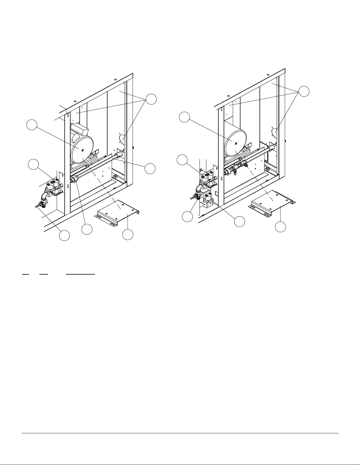
SIDE VIEW - RIGHT HAND
OLD - Before 01/01/97
NEW - After 01/01/97
3
3
1
1
4
LOOK HERE FOR
SERIAL NUMBER
9
7
5
NOTE:
Part is not depicted
at actual size.
2
4
5
**See
NOTE
below.
LOOK HERE FOR
SERIAL NUMBER
6
NOTE:
Part is not depicted
2
at actual size.
Ref. Part
No. No. Description
1 30685 Motor, 115V, 3/4 HP, 1 PH, 2 SP, 60 HZ
(Qty 1) Units before 01/01/97
1 37022 Motor, 115V, 3/4 HP, 1 PH, 2 SP, 60 HZ
(Qty 1) Units after 01/01/97
2 31601 Motor Adapter Bracket
NOTE: For units before 01/01/97 this bracket will not
t the Howell Motor.
3574 Terminal Block, 65 AMP, 600V (Qty 1)
3 21134 Axial Fan, 115V, 3" (Qty 3)
22711 Lug, Grounding & Screw (Qty 1)
4 22190 Dual Solenoid Valve/Pressure Regulator LP
4 M5495 Dual Solenoid Valve/Pressure Regulator NAT
18612 Spring, Solenoid Valve, Nat to LP (Qty 1)
23007 Spring, Solenoid Valve, LP to Nat (Qty 1)
5 R4435 Gas valve, manual
R0364 Knob, Square D, controls manual gas valve
6 R6490 Pilot Valve, Units after 01/01/97
7 3807 Union, for thru pipe Units before 01/01/97
SEPTEMBER 26, 2012 3 AC-500
Page 4
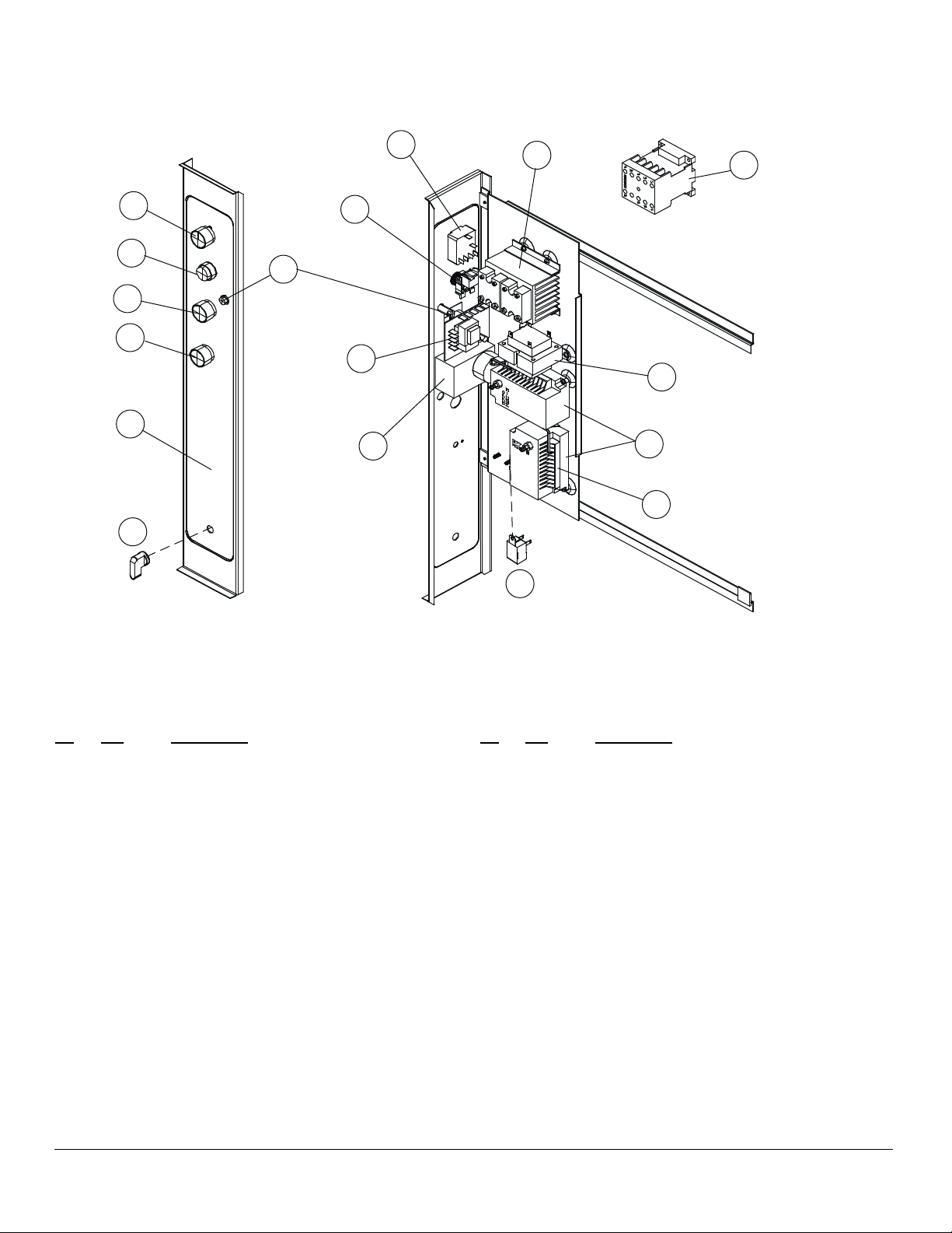
SOLID STATE MANUAL CONTROLS
2
2
13
14
3
2
7
11
10
6
8
1
9
5
16
30851 Control - HSI
Units before 01/01/97
or 20348 Spark Box
Units after 01/01/97
17
4
NOTE:
Picture depicts Part 20348
Spark Box. Please use serial
number for correct part.
Ref. Part
No. No. Description
1 18578 Controller, Temperature (Qty 1)
30712 Probe, Temperature (Qty 1)
18234 Potentiometer, Remote (Qty 1)
2 24684 Knob, Temperature (Qty 1)
3 21068 Mode Selector Switch (4 Position) (Qty 1)
2 24684 Knob, Mode Selector (Qty 1)
4 20349 Buzzer, 120V (Qty 1)
5 18225 Timer, 60 Minute, 120V, 60 HZ (Qty 1)
2 24684 Knob, Timer (Qty 1)
36755 Thermal Switch SPDT, Units after 06/01/2003
6 18295 Switch, Momentary for lights (Push-Button)
(Qty 1)
7 18296 Contact Block, 6 Amp., 600V (Qty 1)
8 18265 Indicator Light, 28V, Red, Round (Qty 1)
Ref. Part
No. No. Description
9 31274 Transformer, 120V to 24V
(Units before 01/01/97 use Qty 2 and Units after
01/01/97 use Qty 1)
10 31767 Contactor, 3 Pole, 120V Coil (Qty 1)
Units before 01/01/97
11 33910 Relay Assy Units after 01/01/97
13 31841 Decal, Lexan Control (Manual) (Qty 1)
14 R0364 Knob, Square D, controls manual gas valve
15 R4435 Gas Valve, manual
NOTE: Gas valves are pictured on page 3
16 30851 Ignition Control, Hot Surface Ignition Units
before 01/01/97
17 20348 Spark Box Units after 01/01/97
SEPTEMBER 26, 2012 4 AC-500
Page 5
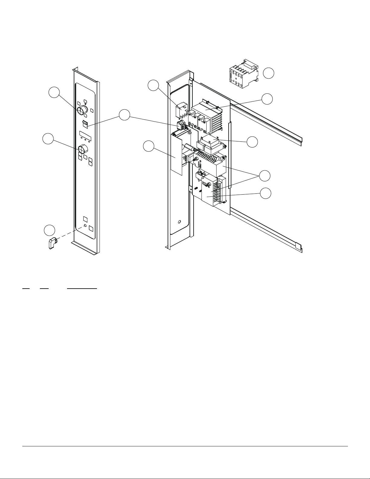
SOLID STATE DIGITAL CONTROLS
5 KEY (PICTURED WITH LIGHTS)
7
31767 Contactor
3
4
5
Before 1/1/97 OR
33910 Relay
After 1/1/97
8
2
1
12
NOTE: Picture depicts Part 20348
Spark Box. Please use serial number
for correct part.
Ref. Part
No. No. Description
1 30658 Controller, Time & Temperature (Qty 1)
30712 Probe, Temperature (Qty 1)
2 24685 Knob, Adjust Temperature (Qty 1)
3 21068 Mode Selector Switch (4 Position) (Qty 1)
4 24684 Knob, Mode Selector (Qty 1)
5 19620 Light Switch, Rocker (Momentary) (Qty 1)
36755 Thermal Switch SPDT, Units after 06/01/2003
6 31274 Transformer, 120V to 24V
(Units before 01/01/97 use Qty 2 and Units after 01/01/97 use Qty 1)
7 31767 Contactor, 3 Pole, 120V Coil (Qty 1)
Units before 01/01/97
8 33910 Relay Assy (Qty 1)
Units after 01/01/97
10 30851 Ignition Control, Hot Surface Ignition Units before 01/01/97
11 20348 Spark Box Units after 01/01/97
12 R0364 Knob, Square D, controls manual gas valve
R4435 Gas Valve, manual
6
30851
10
Ignition Control-HSI
Units before 01/01/97
OR
11
20348
Spark Box
Units after 01/01/97
NOTE: Gas valves are pictured on page 3
SEPTEMBER 26, 2012 5 AC-500
Page 6

INTELLIPLUS CONTROL
13 KEY
31767 Contactor
7
2
4
3
Before 01/01/97
33910 Relay
8
After 01/01/97
5
1
10
Ref. Part
No. No. Description
31901 Probe, Temperature (Qty 1)
1 24181 Knob, Control Time or Temperature (Qty 2)
2 18868 Mode Selector Switch (3 Position) (Qty 1)
3 24684 Knob, Mode Selector (Qty 1)
4 19620 Light Switch, Rocker, Momentary (Qty 1)
5 18265 Indicator Light, 28V, Red, Round (Qty 1)
6 31274 Transformer, 120V to 24V
(Units before 01/01/97 use Qty 2 and Units after 01/01/97 use Qty 1)
7 31767 Contactor, 3 Pole, 120V Coil (Qty 1) Units before 01/01/97
8 33910 Relay Assy (Qty. 1) Units after 01/01/97
10 R0364 Knob, Square D, controls manual gas valve
R4435 Gas Valve, manual Units before 01/01/97
R6490 Pilot Valve Units after 01/01/97
NOTE: Picture depicts Part
20348 Spark Box. Please use
serial number for correct part
6
11
30851 Ignition
Control HSI Before 01/01/97
or
12
20348 Spark Box After 01/01/97
NOTE: Gas valves are pictured on page 3
11 30851 Ignition Control, Hot Surface Ignition Units before 01/01/97
12 20348 Spark Box Units after 01/01/97
SEPTEMBER 26, 2012 6 AC-500
Page 7

CH102 FAST CONTROLS
14 KEY (WITH LIGHTS)
6
4
3
2
1
5
8
7
1
9
Ref. Part
No. No. Description
1 37087 Controller, CH102 (14 Key)
34472 Probe, RTD 12"
2 19620 Light Switch, Rocker, DPST, Momentary
3 24685 Knob, Adjust (Qty 1)
4 21068 Mode Selector Switch (4 Position) (Qty 1)
5 31274 Transformer, 120V to 24V (Qty 1)
36755 Thermal Switch SPDT, Units after 06/01/2003
6 33910 Relay Assy (Qty 1)
7 20348 Spark Box Assy, Nat & LP (Qty 2)
34689 Capacitor Assy, Snubber CH102 control
8 36056 Control Panel & Decal Assy, CH102
9 R0364 Knob, Square D, controls manual gas valve
SEPTEMBER 26, 2012 7 AC-500
Page 8

GAS MANIFOLD ASSEMBLY
MANUFACTURED BEFORE 11/25/1998
SERIAL NUMBER 112598RF008T
1
1
2
2
Ref. Part
No. No. Description
1 31331 Probe, Flame Sensing (Qty 2)
2 30943 Orice, Main Burner, Nat (MTD #46) (Qty 4)
2 31828 Orice, Main Burner, LP (MTD #55) (Qty 4)
33052 Relay & Hardware 24V, for Gas sytem shutoff
SEPTEMBER 26, 2012 8 AC-500
Page 9

GAS MANIFOLD ASSEMBLY
MANUFACTURED AFTER 11/25/1998
SERIAL NUMBER 112598RF008T
3
3
6
1
1
5
2
Ref. Part
No. No. Description
1 30943 Orice, Main Burner, Nat (MTD #46) (Qty 4)
1 31828 Orice, Main Burner, LP (MTD #55) (Qty 4)
2 M2799 Elbow, Union Compression
3 34282 Pilot Ignitor Assy (Qty 2)
5 33488 Tubing, Flex 12" (Qty 1)
6 M0697 Pilot Orice Nat (Qty 2)
6 M2690 Pilot Orice LP (Qty 2)
6
SEPTEMBER 26, 2012 9 AC-500
Page 10

DOOR COMPONENTS
SINGLE DOOR OPTION
OLD - Before 01/01/97 NEW - After 01/01/97
7
8
Doors are not returnable
Ref. Part
No. No. Description
5
4
1
2
3
9
5
Ref. Part
No. No. Description
AFTER JANUARY 01, 1997
1 33886 Door Assy, Glass (Qty 1)
2 31704 Glass Assy, Door (14" x 20") (Qty 1)
3 R6313 Handle
4 R2296 Catch & Latch Assy
20734 Microswitch Assy, Pictured on page 12
33907 Bracket, Door Switch
5 30761 Arm, Door Upper &/or Lower (Qty 2)
31919 Gasket Assy, Perimeter Door
(4 Piece) (Qty 1)
16470 Nameplate Assy., Blodgett 10" (Qty 1)
BEFORE JANUARY 01, 1997
2 31704 Glass Assy, Door (14" x 20") (Qty 1)
7 17946 Catch Assy, Door (Qty 2)
NOTE: One is located on the top of the door and the
other is located on the bottom of the door
31206 Plate, Striker Door Latch (Qty 2)
31240 Microswitch Assy, Door Pictured on page 12
8 35883 Arm, Door Upper (Qty 1)
90004 Bushings, Door Hinge (Set of 2)
31919 Gasket Assy, Perimeter Door (4 Piece) (Qty 1)
Pictured on page 12
16470 Nameplate Assy., Blodgett 10" (Qty 1)
SEPTEMBER 26, 2012 10 AC-500
Page 11

DOOR COMPONENTS
SPECIFIC TO DOUBLE DOOR OPTION
1
3
2
Ref. Part
No. No. Description
1 31721 Door Assy, LH Glass (Qty 1)
2 36113 Door Assy, RH Glass (Qty 1)
3 31753 Catch Assy, Door
37305 Microswitch Assy
31919 Gasket Assy, Perimeter
37304 Gasket Assy, Center
SEPTEMBER 26, 2012 11 AC-500
Page 12

EXTERIOR COMPONENTS
"OLD STYLE" BEFORE 01/01/97
4
2
5
6
2
3
NOTE: The Microswitch is
located behind this louvered
cover piece.
SEPTEMBER 26, 2012 12 AC-500
Page 13

EXTERIOR COMPONENTS
"NEW STYLE" AFTER 01/01/97
2
9
8
NOTE: The Microswitch is located
behind this louvered cover piece.
2
Ref. Part
No. No. Description
7839 Drafthood, Direct Venting, S/S (Qty 1)
7840 Draft Diverter, Canopy Venting, S/S (Qty 1)
2 31919 Gasket Assy, Perimeter
21826 Installation Hose, 36"
21242 Installation Hose, 48"
31595 Cord Set Assy, 6 Feet (Qty 1)
8598 Legs, 25" w/ Bolts, S/S (Set of 4)
92000 Studs, Leg (Set of 4)
7847 Bolts, Leg (Set of 8)
16002 Casters (Sgl Oven) (Set of 4)
19528 Casters, Low Prole (Dbl Oven) (Set of 4)
33425 Casters, Adjustable Low Prole (Dbl Oven)
(Set of 4)
Ref. Part
No. No. Description
BEFORE JANUARY 01, 1997
2 30975 Cover Assy, Combustion Compartment (Qty 1)
4 30974 Body Top, Front (Qty 1)
5 30718 Cover, Control (Qty 1)
AFTER JANUARY 01, 1997
8 33891 Body Side, RH S/S (Qty 1)
11 20734 Microswitch Assy, Door (Qty 1)
Units after 01/01/97
SEPTEMBER 26, 2012 13 AC-500
Page 14

INTERIOR VIEW
3
1
2
Ref. Part
No. No. Description
30988 Retainer, Probe Wire (Qty 2)
1 30677 Rack Support (Qty 2)
2 30676 Rack, Wire (27-3/8" x 23-5/16") (Each)
3 30649 Blower Wheel (Qty 1)
31741 Bulb, Light 25W, 120V, (Qty 2)
35791 Lens, Cover Light (Qty 2)
1
SEPTEMBER 26, 2012 14 AC-500
Page 15

EXCLUSIVE TO EXPORT
Ref. Part
No. No. Description
32241 Motor, 240V, 2 SP, 50/60 HZ
16037 Indicator Light, 250V, Red, Round (Qty 1) CE
20084 Timer, 60 Minute, 240V, 50 HZ (Qty 1) CE
18581 Timer, Adjustable, 240V (Qty 1) CE
18439 Potentiometer, Control (Humidaire) CE (Qty 1)
20350 Buzzer, 240V (Qty 1) CEE
R4435 Gas Valve, Manual 1/2" (Qty 1) CE
53009 Control, Hot Surface Ignitor (Qty 2) CE
M2841 Fitting, Pressure Tap (Qty 1) CE
SEPTEMBER 26, 2012 15 AC-500
 Loading...