

Page 1
Since 1848
INSTALLATION INSTRUCTIONS FOR
AB2A VENTILATION SYSTEM
FOR BLODGETT DOUBLE DECK MT3870
COMPUTERIZED CONVEYOR OVEN
LISTED
BLODGETT OVEN COMPANY
A Division of
G. S. BLODGETT CORPORATION
50 Lakeside Avenue, Box 586, Burlington, Vermont 05402 USA Telephone (800) 3315842, (802) 8603700 Fax: (802)8640183
PN M9519 (3/98)
1998 - G.S. Blodgett Corporation
Page 2

TABLE OF CONTENTS
Delivery and Inspection Page 3. . . . . . . . . . . . . . . . . . . . . . . . . . . . . . . . . . . . . . . . . . . . . . . . . . . . . . . . . . . . . . . . . . . . . . . . . . . . . . .
Installation Page 4. . . . . . . . . . . . . . . . . . . . . . . . . . . . . . . . . . . . . . . . . . . . . . . . . . . . . . . . . . . . . . . . . . . . . . . . . . . . . . . . . . . . . . . . . .
Cleaning and Maintenance Page 21. . . . . . . . . . . . . . . . . . . . . . . . . . . . . . . . . . . . . . . . . . . . . . . . . . . . . . . . . . . . . . . . . . . . . . . . . . .
Servicing Page 22. . . . . . . . . . . . . . . . . . . . . . . . . . . . . . . . . . . . . . . . . . . . . . . . . . . . . . . . . . . . . . . . . . . . . . . . . . . . . . . . . . . . . . . . . . .
Air Flow Measurement Page 23. . . . . . . . . . . . . . . . . . . . . . . . . . . . . . . . . . . . . . . . . . . . . . . . . . . . . . . . . . . . . . . . . . . . . . . . . . . . . . .
AGENCY APPROVALS
The InVent Hood Systems are Listed by Underwriters Laboratories Inc. (UL) in category YYCW as Exhaust Hoods Without
Exhaust Dampers. They are intended to be installed in accordance with NFPA 96, the Standard for Ventilation Control and
Fire Protection of Commercial Cooking Operations. The basic Standard used by UL to investigate products in this category
is UL 710, the Standard for Exhaust Hoods for Commercial Cooking Equipment.
These hoods are considered to be Type 1 according to the International Mechanical Code (IMC); that is, they are, installed
at or above all commercial food heatprocessing equipment that produces grease vapors or smoke." IMC is published by
the International Code Council, Inc. and is compatible with codes written by the Building Officials and Code Administrators
International, Inc., (BOCA), the International Conference of Building Officials (ICBO), and Southern Building Code Congress
International, Inc. (SBCCI). The Uniform Mechanical Code (UMC) published by ICBO defines a Type I Hood as, a kitchen
hood for collecting and removing grease and smoke." A Type II Hood is a general hood for collecting and removing steam,
vapor, heat or odors." The hood type is determined by the intended use. UL tested and approved the InVents for use in the
Type I environment.
These Hoods are NSF approved to ANSI/NSF21992, Food Equipment
corrosion resistant. Furthermore, that there be no sharp corners or open seams where food, residue or soil collect.
Page 1
. ANSI/NSF21992 requires that all materials used be
Page 3

DELIVERY AND INSPECTION
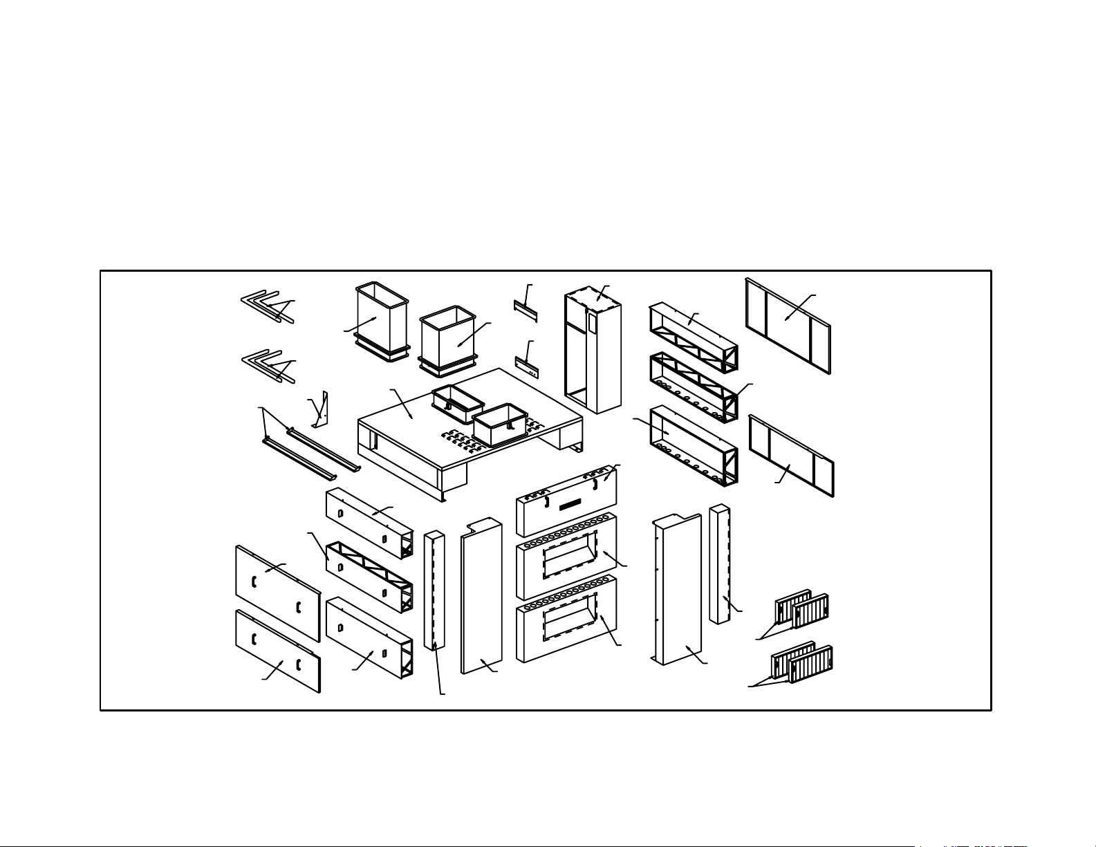
Upon arrival of your AB2A ventilator, inspect the crate for damage and inform the shipper if necessary. Carefully unpack the
unit and match the parts to the list below.
Item Blodgett P/N Qty Description
A AB2AA 1 AMU/Exhaust Manifold
A1 AB2AA1 1 AMU Duct Extension
A2 AB2AA2 1 Exhaust Duct Extension
A3 AB2AA3 1 Top Exhaust Enclosure Bracket, Left
A4 AB2AA4 2 Exhaust Duct Ceiling Trim
A5 AB2AA5 2 AMU Duct Ceiling Trim
B AB2AB 1 AMU Support Bracket, Right
C AB2AC 1 AMU Support Bracket, Left
D AB2AD 1 Lower Front AMU Plenum
E AB2AE 1 Middle Front AMU Plenum
F AB2AF 1 Upper Front AMU Plenum
G AB2AG 2 Filter Trough/Receptacle
H1 M9500 2 Filter,10x16"
H2 M9501 2 Filter, 10 x 20"
J AB2AJ 1 Vertical Exhaust Manifold, Left
K AB2AK 1 Cooling Fan Exhaust Enclosure
L AB2AL 1 Upper Top End Enclosure, Right
L1 AB2AL1 1 Lower Top End Enclosure, Right
L2 AB2AL2 1 Upper Heat Sheild, Right
M AB2AM 1 Lower End Enlosure, Right
M1 AB2AM1 1 Lower Heat Shield, Right
N AB2AN 1 Upper Top End Enclosure, Left
N1 AB2AN1 1 Lower Top End Enclosure, Left
N2 AB2AN2 1 Upper Heat Shield, Left
P AB2AP 1 Lower End Enclosure, Left
P1 AB2AP1 1 Lower Heat Shield, Left
Q AB2AQ 1 Hardware Bag (includes the following)
Q1 M9519 1 Installation Instructions
Q2 M0652 4 1/4"20 Lock Nut
Q3 M0222 8 1/4"20 x 1/2" Hex Head Screw
Q4 R1417 1 1/4"20 Shoulder Bolt
Page 2
Page 4
Item Blodgett P/N Qty Description
Q5 M9509 1 1/4"20 x 1/2" Thumb Screw with Shoulder Washer
Q6 M3828 2 Stacking Pins
Q7 653 12 1/4" Flat Washer
Q8 M6315 3 #1024 x 1/2" Slotted Hex Head Screw
R AB2AR 3 Oven Securing Clip
S AB2AS 1 Mounting Bracket (Rev. A)
S1 AB2AS1 1 Mounting Bracket (Rev. B)
T AB2AT 1 Vertical Exhaust Manifold, Right
[G]
[P1]
[A4]
[A5]
[A3]
[N1]
[N2]
[A2]
[P]
[A]
[N]
[J]
[A1]
[C]
[S1]
[S]
[K]
[M]
[F]
[D]
[L2]
[L]
[L1]
[M1]
[E]
[T]
[H1]
[B]
[H2]
Figure 1
Page 3
Page 5
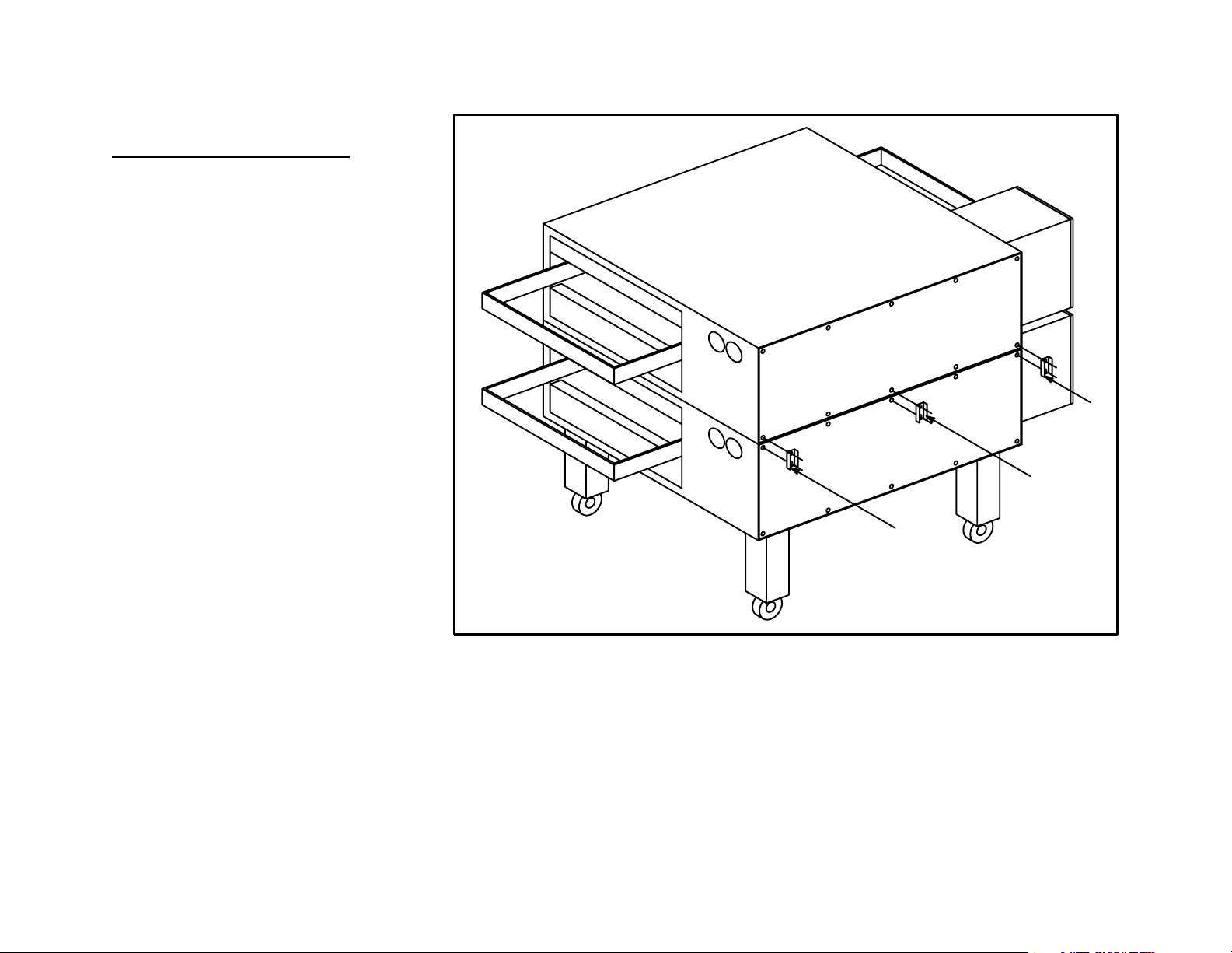
INSTALLATION
Step 1 - Oven Preparation
Assemble both ovens as described in
the Blodgett MT3870 OwnerOperator
Manual.
Use the three (3) Oven Securing Clips
[R] to secure the two decks together
and prevent shifting. (See Figure 2)
[R]
[R]
[R]
Page 4
Figure 2
Page 6
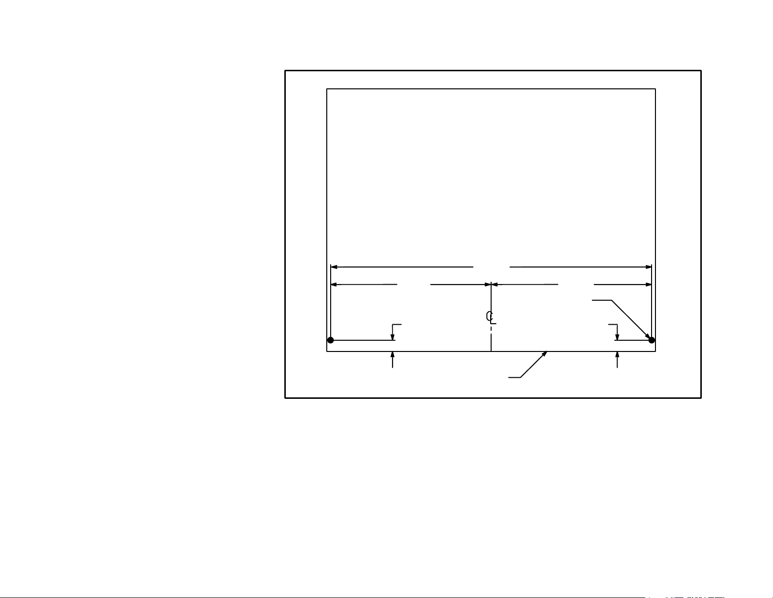
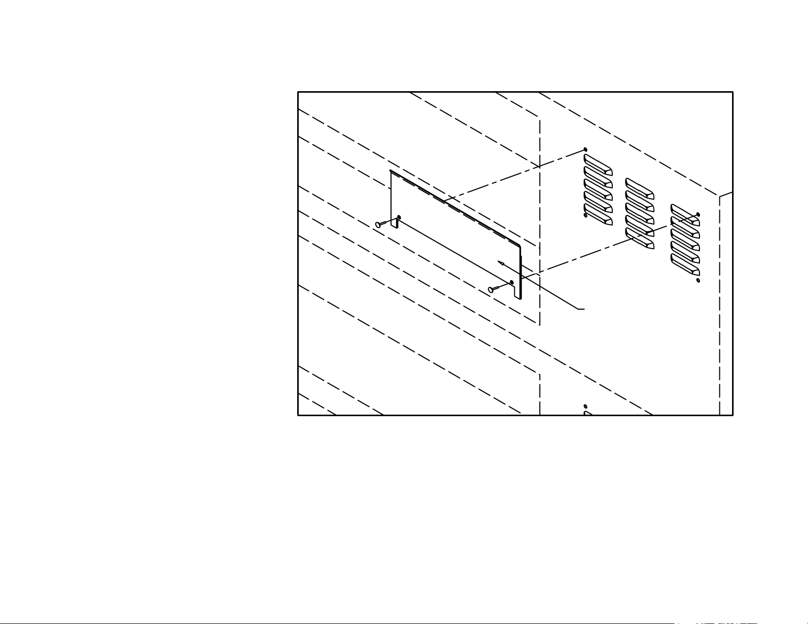
If the ovens are equipped with align
ment knockouts, remove the two (2)
front indents. Those holes should
match the two (2) shown in Figure 3.
If the ovens are not equipped with align
ment indents, locate the center, front,
top edge of the upper oven. Drill two (2)
7/16" diameter holes in the top of the
oven as indicated in Figure 3. The holes
should penetrate both the top skin" of
the oven as well as the angle frame
members. There is no need to penetrate
the top of the oven by more than 7/8".
68 1/2
34 1/4 34 1/4
7/16 (2 PLS)
2 7/162 7/16
Page 5
FRONT OF OVEN
Figure 3
Page 7
If the ovens are equipped with louvered
cooling fan exhaust outlets, attach the
Cooling Fan Exhaust Enclosure Mount
ing Plate [S1] to the top oven using two
#1024x1/2" screws [Q8] provided. See
Figure 4. For older oven models use the
alternate Cooling Fan Exhaust Enclo
sure Mounting Plate [S].
[S1]
Page 6
Figure 4
Page 8
Step 2 - AMU Installation:
Thread two (2) Stacking Pins [Q6] into
the fittings on the bottom of the AMU/Ex
haust Manifold/Duct Connection as
sembly [A]. Carefully lift the AMU/Ex
haust Manifold/Duct Connection as
sembly [A] and place it on top of the
ovens. The alignment pins will fit into the
alignment holes in the top of the oven
and prevent the AMU/Exhaust Manifold/
Duct Connection assembly [A] from
shifting on top of the oven. (See
Figure 5)
If the AMU/Exhaust Manifold/Duct Con
nection assembly [A] does seat tightly
against the top of the oven, apply a bead
of high temperature silicone sealant in
the seam between the AMU/Exhaust
Manifold/Duct Connection assembly
[A] and the sides of the oven.
[A]
[Q6]
Silicone
Sealant
Alignment Hole
Page 7
Figure 5
Page 9
Attach the AMU Support Bracket, Right
[B] to the AMU/Exhaust Manifold/Duct
Connection assembly [A] using two (2)
1/4"20 x 1/2" Hex Head Cap Screws
[Q3] and 1/4" Flat Washers [Q7]. (See
Figure 6)
Attach the AMU Support Bracket, Left
[C] to the AMU/Exhaust Manifold/Duct
Connection [A] assembly using two (2)
1/4"20 x 1/2" Hex Head Cap Screws
[Q3] and 1/4" Flat Washers [Q7]. (See
Figure 6)
[Q3] (4)
[Q7] (4)
[B]
[C]
Page 8
Figure 6
Page 10

Secure the AMU Support Bracket, Right
[B] below the right front support leg
mounting flange. (See Figure 7) Use the
same inner, front bolt and washer that
secures the leg in place to hold the AMU
Support Bracket, Right [B].
Secure the AMU Support Bracket, Left
[C] below the left front support leg
mounting flange. (See Figure 7) Use the
same inner, front bolt and washer that
secures the leg in place to hold the AMU
Support Bracket, Left [C].
The AMU Support Bracket, Right [B]
and AMU Support Bracket, Left [C]
should be parallel and square and held
firmly against the front of the ovens.
[B]
Page 9
Figure 7
Page 11

Place the Lower Front AMU Panel [D] on
the lower pins of the AMU Support
Bracket, Right [B] and AMU Support
Bracket, Left [C]. (See Figure 8)
Place the Middle Front AMU Panel [E] in
the middle pins of the AMU Support
Bracket, Right [C] and AMU Support
Bracket, Left [D].
[B]
Place the Upper Front AMU Panel [F] in
the upper pins of the AMU Support
Bracket, Right [C] and AMU Support
Bracket, Left [D].
[E]
[F]
[D]
[C]
Figure 8
Page 10
Page 12

Step 3 - Exhaust Installation:
Attach the Vertical Exhaust Manifold,
Right [T] to the AMU Support Bracket,
Right [B] with two (2) 1/4"20 x 1/2"
Thumb Screws [Q5]. (See Figure 9)
Attach the Vertical Exhaust Manifold,
Left [J] to the AMU Support Bracket, Left
[C] with two (2) 1/4"20 x 1/2" Thumb
Screws [Q5]. (See Figure 9)
[A]
[Q5]
[J]
[Q5]
[T]
[K]
Page 11
Figure 9
Page 13

Attach the Cooling Fan Exhaust Enclo
sure [K] to the AMU/Exhaust Manifold/
Duct Connection [A].
Flange
Ta b
[K]
On ovens with louvered exhaust ports,
remove the tab from the Cooling Fan Ex
haust Enclosure [K] and replace the fas
teners into the holes. The Cooling Fan
Exhaust Enclosure [K] will be held in
place by the Cooling Fan Exhaust En
closure Mounting Plate [S or S1].
For ovens that have separate cooling
fans and grills on the right side (oppo
site the control cabinets), a tab on the
Cooling Fan Exhaust Enclosure [K] will
fit over the rivet in the AMU/Exhaust Man
ifold/Duct Connection [A]. (See
Figure 10) The flange on the Cooling
Fan Exhaust Enclosure [K] should rest
on top of the oven before the rivet bot
toms out in the slot of the flange.
[S or S1]
Oven
[A]
Rivet
Page 12
Figure 10
Page 14

Caution: The hole location described below should not interfere with any oven control center components. Care must
be taken when locating and drilling this hole to avoid damage to internal components.
Drill one (1) 1/4" diameter hole into the
upper control cabinet as shown in
Figure 11. The distance from the top of
the upper oven to the center line of the
hole should be the same as the distance
from the top of the upper oven to the
center line of the pin welded in the sur
face of the Vertical Exhaust Manifold,
Left [J].
Insert one (1) 1/4"-20 Shoulder Bolt
[Q4] through the hole and secure it in
place with one (1) 1/4" Flat Washer [Q7]
and one (1) 1/4"-20 Lock Nut [Q2].
1
15 9/16
Shoulder Bolt [Q5]
Page 13
FRONT VIEW
Figure 11
Page 15

Locate the Bracket, Top Exhaust Enclo
sure, Left Hand [A3] at the junction of
the AMU/Exhaust Manifold, Duct As
sembly [A] and the forward, inboard
edge of the upper oven control cabinet.
(See Figure 12). The forward edge of
the Bracket, Top Exhaust Enclosure,
Left Hand [A3] should be vertical. There
should be a minimum of 343/16" be
tween the front face of the control cabi
net and the rear face of the Vertical Ex
haust Manifold, Left [J]. If necessary,
loosen the bolts that hold the control
cabinet to the oven and shift the control
cabinet rearward.
Using the Bracket, Top Exhaust Enclo
sure, Left Hand [A3] as a template, draw
marks on the top of the control cabinet.
Drill one (1) 1/4" diameter hole in the
spot marked. Secure the Bracket, Top
Exhaust Enclosure, Left Hand [A3] in
place using 1/4"20 x 1/2" Hex Head
Cap Screws [Q3], 1/4" Flat Washers
[Q7], and 1/4"20 Lock Nuts [Q2] as
shown in Figure 12.
[Q2]
[Q7]
[Q3]
[A3]
Figure 12
Page 14
Page 16

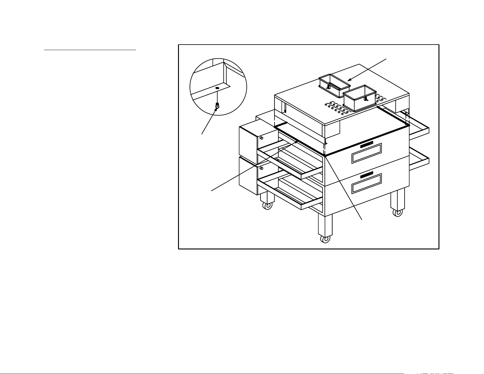
Install one (1) Filter Trough/Receptacle
[G] into the opening in each end of the
AMU/Exhaust Manifold/Duct Connec
tion [A] assembly. The tabs in the Filter
Trough/Receptacle [G] fit into the slots
on the sides of the openings in the AMU/
Exhaust Manifold/Duct Connection [A]
assembly. (See Figure 13)
Insert one (1) 10 x 16" Filter [H1] and
one (1) 10 x 20" Filter [H2] into each end
of the AMU/Exhaust Manifold/Duct Con
nection [A] assembly. Install the top of
the Filter [H1 and H2] into the channel
in the top of the AMU/Exhaust Manifold/
Duct Connection [A] assembly first.
Then allow the bottom of the Filter [H1
and H2] to drop into the Filter Trough/
Receptacle [G].
Repeat the above procedure on the oth
er end of the oven for the remaining Fil
ter Trough/Receptacle [G], one (1) 10 x
16" Filter [H1] and one (1) 10 x 20" Filter
[H2].
[G]
Page 15
Figure 13
Page 17

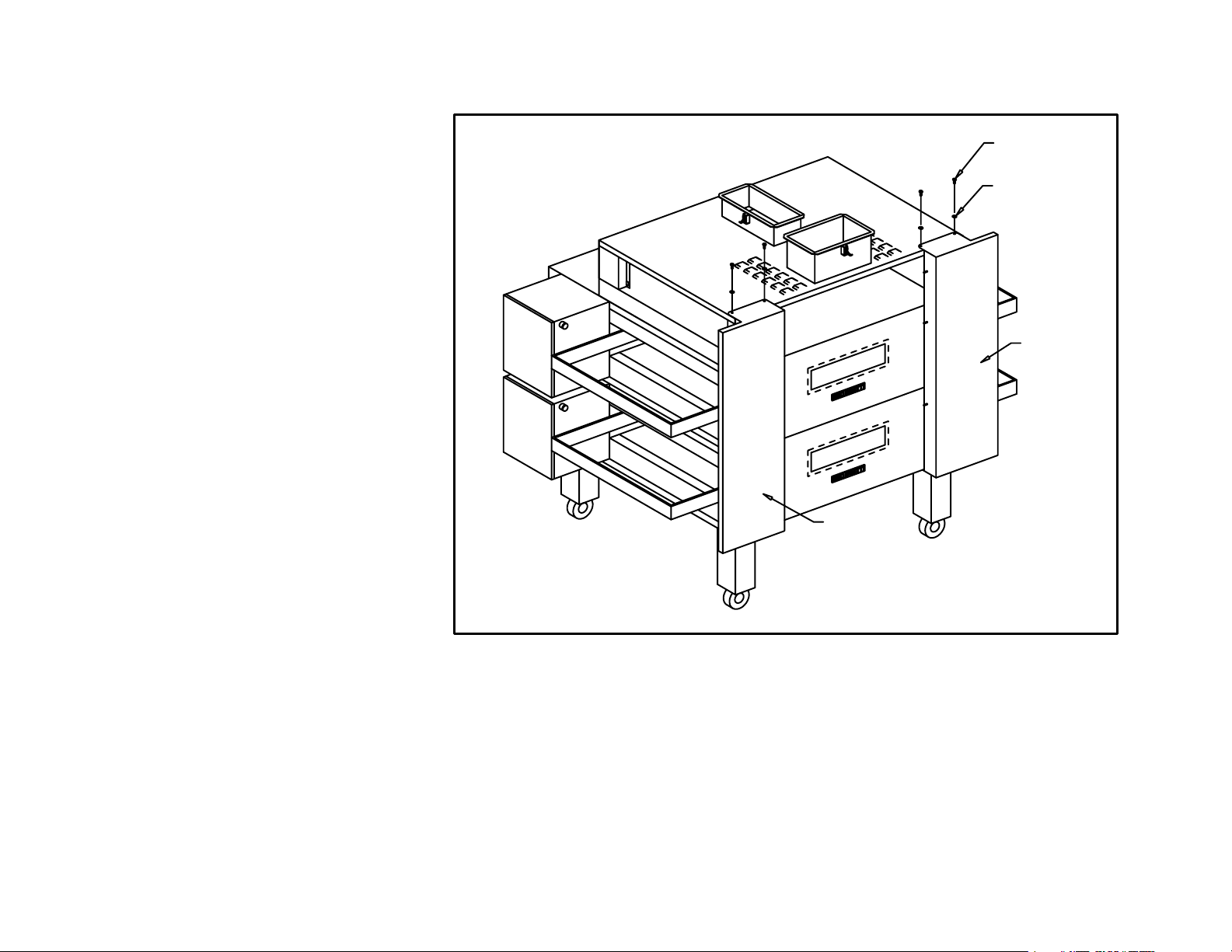
Mount the Lower Top End Enclosure,
Right Hand [L1] in place. The slots on
the sides toward the rear of the Lower
Top End Enclosure, Right Hand [L1] will
fit over the pins in the Cooling Fan Ex
haust Enclosure [K] and the Vertical Ex
haust Manifold, Right Hand [T].
Mount the Upper Top End Enclosure,
Right Hand [L] in place. The angle to the
rear of the Upper Top End Enclosure,
Right Hand [L] will fit into the angle in the
AMU/Exhaust Manifold/Duct Connec
tion [A].
Mount the Lower End Enclosure, Right
Hand [M] in place. The slots on the sides
towards the rear of the Lower End Enclo
sure, Right Hand [M] will fit over the pins
in the Cooling Fan Exhaust Enclosure [K]
and the Vertical Exhaust Manifold, Right
Hand [T]. (See Figure 14)
[A]
[T]
[L1]
[L]
[M]
[K]
Page 16
Figure 14
Page 18

Mount the Upper Right Hand Heat
Shield [L2] in place by locating the slots
over the pins in the Upper Top End En
closure, Right Hand [L].
[L]
Mount the Lower Right Hand Heat Shield
[M1] in place by locating the slots over the
pins in the Lower End Enclosure, Right
Hand [M]. (See Figure 15)
[L1]
[L2]
[M1]
[M]
Figure 15
Page 17
Page 19

Mount the Lower Top End Enclosure,
Left Hand [N1] in place. The slots on the
sides towards the rear of the Lower Top
End Enclosure, Left Hand [N1] will fit
over the pins in the Bracket, Top Ex
haust Enclosure, Left Hand [A3] and the
Vertical Exhaust Manifold, Left Hand [J].
Mount the Upper Top End Enclosure,
Left Hand [N] in place. The angle to the
rear of the Lower End Enclosure, Left
Hand [N] will fit into the angle in the
AMU/Exhaust Manifold/Duct Connection
[A].
[A]
[A3]
[N1]
Mount the Lower End Enclosure, Left
Hand [P] in place. The slots on the sides
towards the rear of the Lower End En
closure, Left Hand [P] will fit over the
Shoulder Bolt [Q5] in the control cabi
net and the pin on the Vertical Exhaust
Manifold, Left Hand [J]. (See Figure 16).
[N]
[P]
[J]
Figure 16
Page 18
Page 20

Mount the Upper Left Hand Heat Shield
[N2] in place by locating the slots over
the pins in the Upper Top End Enclo
sure, Left Hand [N].
Mount the Lower Left Hand Heat Shield
[P1] in place by locating the slots over
the pins in the Lower End Enclosure,
Left Hand [P]. (See Figure 17).
[N]
[N2]
[P1]
Page 19
[P]
Figure 17
Page 21

Step 4 - Duct Connection:
Note: The Duct Collar Extensions [A1 and A2] are designed to remain in place when the oven is rolled away for maintenance
or cleaning. Therefore, they should be rigidly fastened to the ceiling structure as they are not intended to support the
weight of the duct work and/or fans.
Roll the oven into its operating location.
Locate the Exhaust Duct Extension [A2]
on top of the exhaust duct collar (part of
the AMU/Exhaust Manifold/Duct Con
AMU Duct
Exhaust
Duct
nection [A]) and secure it in place with
the two (2) overcenter latches. The ex
haust duct extension is designed to
penetrate an eight foot (8'0") tall ceiling
by approximately two inches (2"). Con
nect the duct from the exhaust fan to the
Finished Ceiling
[A1]
[A]
[A2]
[A]
Exhaust Duct Extension [A2]. (See
Figure 18)
Locate the AMU Duct Extension [A1] on
top of the Air Make Up duct collar (part
Wall
of the AMU/Exhaust Manifold/Duct Con
nection [A]) and secure it in place with
the two (2) overcenter latches. The
AMU duct extension is also designed to
penetrate an eight foot tall ceiling by
approximately two inches (2"). Connect
the duct from the Air Make Up fan to the
AMU Duct Extension [A1].
Page 20
Figure 18
Page 22

CLEANING AND MAINTENANCE
Caution: The oven and the ventilation system get hot during operation. Allow the oven/ventilation system assembly
to cool so as to avoid possible injury.
Note: NFPA 96, Standard for Ventilation Control and Fire Protection of Commercial Cooking Operations, requires that "hoods,
grease removal devices, exhaust fans, and ducts shall have a clearance of at least 18" (457.2 mm) to combustible mate
rial, 3" (76.2 mm) to limited combustible material, and 0" (0 mm) to noncombustible material." The AB2A InVent is
equipped with louvers on the top of the hood which supply makeup air to the general vicinity of the oven and help to
cool the area around the oven. DO NOT store or place items on top of the hood.
Every month:
Remove the Heat Shields [L2, M1, N2 and P1] and End Enclosures [L, L1, M, N, N1 and P] by lifting them up and pulling
them away from the oven. Remove the Filters [H1 and H2] by lifting them up and then swinging the bottom out and down.
Remove the Filter Trough Receptacles [G]. Clean the parts by running them through a dishwasher or wash them by hand
with hot, soapy water. Do not use scouring pads (plastic or metal) on the exterior surfaces as they will scratch and
mar the exterior finish. Rinse the panels in warm water and dry them. Install the Filter Trough/Receptacles, Filters, End
Enclosures and Heat Shields as described on pages 15 through 19.
Every three (3) months:
Remove the Heat Shields [L2, M1, N2 and P1] and End Enclosures [L, L1, M, N, N1 and P] by lifting them up and pulling
them away from the oven. Remove the Filters [H1 and H2] by lifting them up and then swinging the bottom out and down.
Remove the Filter Trough Receptacles [G]. Lift off the Cooling Fan Exhaust Enclosure [K]. Remove the Vertical Exhaust
Manifolds, [T and J], by removing the thumb screws [Q5]. Clean the parts by running them through a dishwasher or wash
them by hand with hot, soapy water. Do not use scouring pads (plastic or metal) on the exterior surfaces as they will
scratch and mar the exterior finish. Wipe out the exhaust channel portion of the AMU/Exhaust Manifold/Duct Connection
[A] assembly. Brush and clean the louvers or guards of the oven cooling fans. Dry the parts and return them to their posi
tions as described in the Exhaust Installation portion of this manual (pages 11 through 18).
Note: This regular maintenance is in addition to the daily, quarterly, semiannual and annual cleaning schedule included in
the oven operating manual.
Page 21
Page 23

SERVICING
For servicing the oven, disconnect the
gas and electric services from the oven
as described in the MT3870 Owner Op
erator Manual. To move the oven/ven
tilation system assembly for mainte
nance, release the overcenter latches
on the exhaust and Air MakeUp duct
collars. Slide the clamping collars up
and secure them out of the way. Release
the brakes on the front locking casters
of the oven assembly. Roll the oven out
away from the wall. (See Figure 19).
[A2]
Clamping
Collars
OverCenter
Latches
Exhaust Duct
AMU Duct
[A1]
Clamping
Collar
A
Page 22
B
Figure 19
Page 24

AIR FLOW MEASUREMENT
Ports are provided on both the exhaust
and makeup air duct collars of the
AMU/Exhaust Manifold/Duct Connec
tion [A] assembly. (See Figure 20). The
ports are sealed with 1/4"20 threaded
fasteners. After removing the threaded
fasteners, a manometer can be con
nected to the ports using 1/4" soft vinyl
tubing. After adjusting the air flow using
the manometer and the graphs on the
following pages, the tubing is to be re
moved and the threaded fasteners rein
stalled into the ports. High temperature
sealant should be applied to the threads
of the fastener inserted into the exhaust
duct port to ensure a greasetight seal.
Pressure
Ports
Figure 20
Page 23
Page 25

The recommended minimum exhaust air flow is onethousand, sixhundred cubic feet per minute (1600 CFM). The recom
mended maximum makeup air flow is onethousand twohundred cubic feet per minute (1200 CFM). The recommended
net amount of air exhausted from the kitchen is fourhundred cubic feet per minute (400 CFM). The ventilator will perform
satisfactorily with onehundred percent (100%) makeup air. However, it is generally recommended that the kitchen area be
slightly negative in pressure relative to the rest of the building.
Exhaust air static pressure should be taken at the port provided on the Exhaust Duct on the AMU/Exhaust Manifold/Duct
Connection [A] with a manometer. See Figure 20 for port location. Refer to the chart below to reference static pressure to
air flow. A static pressure of one inch of water column (1.0" w.c.) is recommended to achieve an air flow of sixteenhundred
cubic feet per minute (1600 CFM).
AB2A Exhaust Air Flow
2500
2000
1500
1000
Cubic Feet per Minute
500
0
0.0 0.2 0.4 0.6 0.8 1.0 1.2 1.4 1.6 1.8
Static Pressure (inches w.c.)
Page 24
Page 26

Makeup air should be tempered to prevent temperatures from dropping below 40F (4.4C) or exceeding 90F (32.2C).
The ventilator will operate satisfactorily at temperatures outside of these limits, however, operator comfort may be affected.
Additional loading of the building's Heating Ventilation and Air Conditioning (HVAC) system may also result.
Makeup air static pressure should be taken at the port provided on the Supply Duct on the AMU/Exhaust Manifold/Duct Con
nection [A] with a manometer. See Figure 20 for port location. Refer to the chart below to reference static pressure to air flow.
A static pressure of ninehundredths of an inch of water column (0.09" w.c.) is recommended to achieve an air flow of twelve
hundred cubic feet per minute (1200 CFM).
AB2A MakeUp Air Flow
2500
2000
1500
1000
Cubic Feet per Minute
500
0
0.00 0.05 0.10 0.15 0.20 0.25
Static Pressure (inches w.c.)
Page 25
Page 27

Figure 21
Page 26
 Loading...