

Page 1
900 SERIES
ROASTING, BAKING AND PIZZA OVEN
INSTALLATION - OPERATION - MAINTENANCE
BLODGETT OVEN COMPANY
www.blodgett.com
44 Lakeside Avenue, Burlington, Vermont 05401 USA Telephone: (802) 658-6600 Fax: (802)864-0183
PN 11356 Rev L (11/17)
© 2017 - G.S. Blodgett Corporation
Page 2

Your Service Agency’s Address:
Model
Serial number
Oven installed by
Installation checked by
Page 3

IMPORTANT
TABLE OF CONTENTS
WARNING: Improper installation, adjustment, alternation,
service or maintenance can
cause property damage, injury or death. Read the instllation, operation and maintenance instructions thoroughly
before installing or servicing
this equipment.
INSTRUCTIONS TO BE FOLLOWED IN THE EVENT THE
USER SMELLS GAS MUST BE
POSTED IN A PROMINENT LOCATION. This information may
be obtained by contacting your
local gas supplier.
FOR YOUR SAFETY
Do not store or use gasoline or
other ammable vapors or liquids in the vicinity of this or any
other appliance.
The information contained in this
manual is important for the proper installation, use, and maintenance of this oven. Adherence
to these procedures and instructions will result in satisfactory
baking results and long, trouble free service. Please read
this manual carefully and retain
it for future reference.
INSTALLATION
Oven Description and Specications ....................................... 2
Delivery and Location .................................................... 4
Oven Assembly .......................................................... 5
Packaging ........................................................... 5
Leg Attachment ...................................................... 5
Caster Attachment .................................................... 5
Double Section Assembly ............................................. 6
Ultra Rokite Deck .................................................... 6
Steam Injection .......................................................... 7
Ventilation ............................................................... 8
Utility Connections - Standards and Codes ................................ 10
Gas Connection......................................................... 11
Gas Piping.......................................................... 11
Pressure Regulation and Testing ...................................... 12
Gas Hose Restraint ................................................. 13
Initial Startup ........................................................... 14
OPERATION
Safety Information ....................................................... 15
Oven Control ........................................................... 16
Suggested Times and Temperatures ...................................... 17
MAINTENANCE
Cleaning and Preventative Maintenance .................................. 19
Troubleshooting Guide .................................................. 20
ERRORS: Descriptive, typographic or pictorial errors are
subject to correction. Specications are subject to change
without notice.
Page 4
Installation
Oven Description and Specications
The 900 Series enjoys the distinction of having the longest continuous production run of any oven manufactured
by the G. S. Blodgett Company since its founding in 1848.
The rst 900 oven was marketed in 1940 and while advancements in metallurgy and more convenient and reliable controls have been incorporated over the years, the
basic design of this unit has remained unchanged since
its inception.
GAS RATINGS
Natural Gas Propane
US Units SI Units US Units SI Units
Heating Value 1000 BTU/hr 37.3 MJ/m3 2550 BTU/hr 95.0 MJ/m3
Specic Gravity (air=1.0) 0.63 0.63 1.53 1.53
Gas Manifold Pressure 5.0” W.C. 1.25 kPa 10.0” W.C. 2.49 kPa
Oven Input
901
911
911P
951
961
961P, 966, 981
Main Burner Orice Size
901
911
911P
951
961
961P, 966, 981
Pilot Burner Orice Size 0.18” .45 mm .010” .25 mm
NOTE: * - Multiple Twist Drill
NOTE: Orice sizes given are at sea level.
22,000 BTU
20,000 BTU
27,000 BTU
38,000 BTU
37,000 BTU
50,000 BTU
45 MTD*
46 MTD*
42 MTD*
34 MTD*
34 MTD*
30 MTD*
In establishing this record, the 900 Series has set industry
wide standards for excellence in baking characteristics,
performance, and reliability. In its primary applications, it
remains unsurpassed for product quality. Simplicity of design and quality construction throughout assure years of
trouble-free service if equipment is installed properly and
given minimal periodic maintenance.
6.4 KW
5.9 KW
7.9 KW
11.1 KW
10.8 KW
14.6 KW
2.08 mm
2.05 mm
2.35 mm
2.8 mm
2.8 mm
3.25 mm
22,000 BTU
20,000 BTU
27,000 BTU
38,000 BTU
37,000 BTU
50,000 BTU
54 MTD*
55 MTD*
53 MTD*
49 MTD*
49 MTD*
45 MTD*
6.4 KW
5.9 KW
7.9 KW
11.1 KW
10.8 KW
14.6 KW
1.39 mm
1.3 mm
1.5 mm
1.85 mm
1.85 mm
2.1 mm
2
Page 5
Installation
Oven Description and Specications
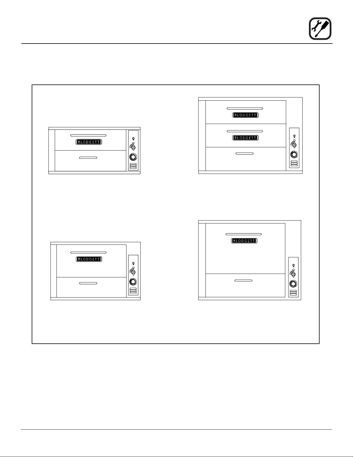
7” High Compartment
911 - 33” x 22”
911-P - 33” x 22”
961 - 42” x 32”
961-P - 42” x 32”
12” High Compartment
901 - 33” x 22”
951 - 42” x 32”
Two 7” High Compartments
981 - 42” x 32”
16” High Compartment
966 - 42” x 32”
Figure 1
3
Page 6

Installation
Delivery and Location
DELIVERY AND INSPECTION
All Blodgett ovens are shipped in containers to prevent
damage. Upon delivery of your new oven:
• Inspect the shipping container for external damage.
Any evidence of damage should be noted on the
delivery receipt which must be signed by the driver.
• Uncrate the oven and check for internal damage.
Carriers will accept claims for concealed damage if
notied within fteen days of delivery and the shipping container is retained for inspection.
The Blodgett Oven Company cannot assume responsibility for loss or damage suffered in transit. The carrier assumed full responsibility for delivery in good order when
the shipment was accepted. We are, however, prepared
to assist you if ling a claim is necessary.
OVEN LOCATION
The well planned and proper placement of your oven will
result in long term operator convenience and satisfactory
performance.
The following clearances must be maintained between
the oven and any combustible or non-combustible construction.
• Oven body right side - 6” (15cm)
• Oven body left side - 6” (15cm)
• Oven body back - 6” (15cm)
• Single and stacked oven bottom - 6” (15cm)
Area must be accessible for proper servicing.
NOTE: On gas models, routine servicing can usually be
accomplished within the limited movement provided by the gas hose restraint. If the oven needs
to be moved further from the wall, the gas must
rst be turned off and disconnected from the oven
before removing the restraint. Reconnect the restraint after the oven has been returned to its normal position.
It is essential that an adequate air supply to the oven be
maintained to provide a sufcient ow of combustion and
ventilation air.
• Place the oven in an area that is free of drafts.
• Keep the oven area free and clear of all combus-
tibles such as paper, cardboard, and ammable
liquids and solvents.
• Do not place the oven on a curb base or seal to a
wall. Either condition will restrict the proper ow of
combustion and ventilation air resulting in damage to
the oven.
4
Page 7
Installation
Oven Assembly
PACKAGING
Before beginning assembly of the oven, check for all necessary components. In addition to the oven itself, legs, a
proper vent, and/or other accessories may be required.
900 Series ovens are packaged as follows:
Single Section Ovens
The following are packed in the oven:
• A set of 27-1/2” (70 cm) legs with attaching hardware.
• Either a canopy or direct vent as specied
• Either a natural gas or propane gas pressure regula-
tor as required.
Multiple Section Ovens
The following are packed inside the bottom section:
• A set of legs of the appropriate length
• Either a canopy or direct vent as specied
• A back pipe of appropriate length with either a natural gas or propane gas regulator attached
Additional Packaging
• Ultra Rokite decks for all 900 Series are packed in a
separate crate.
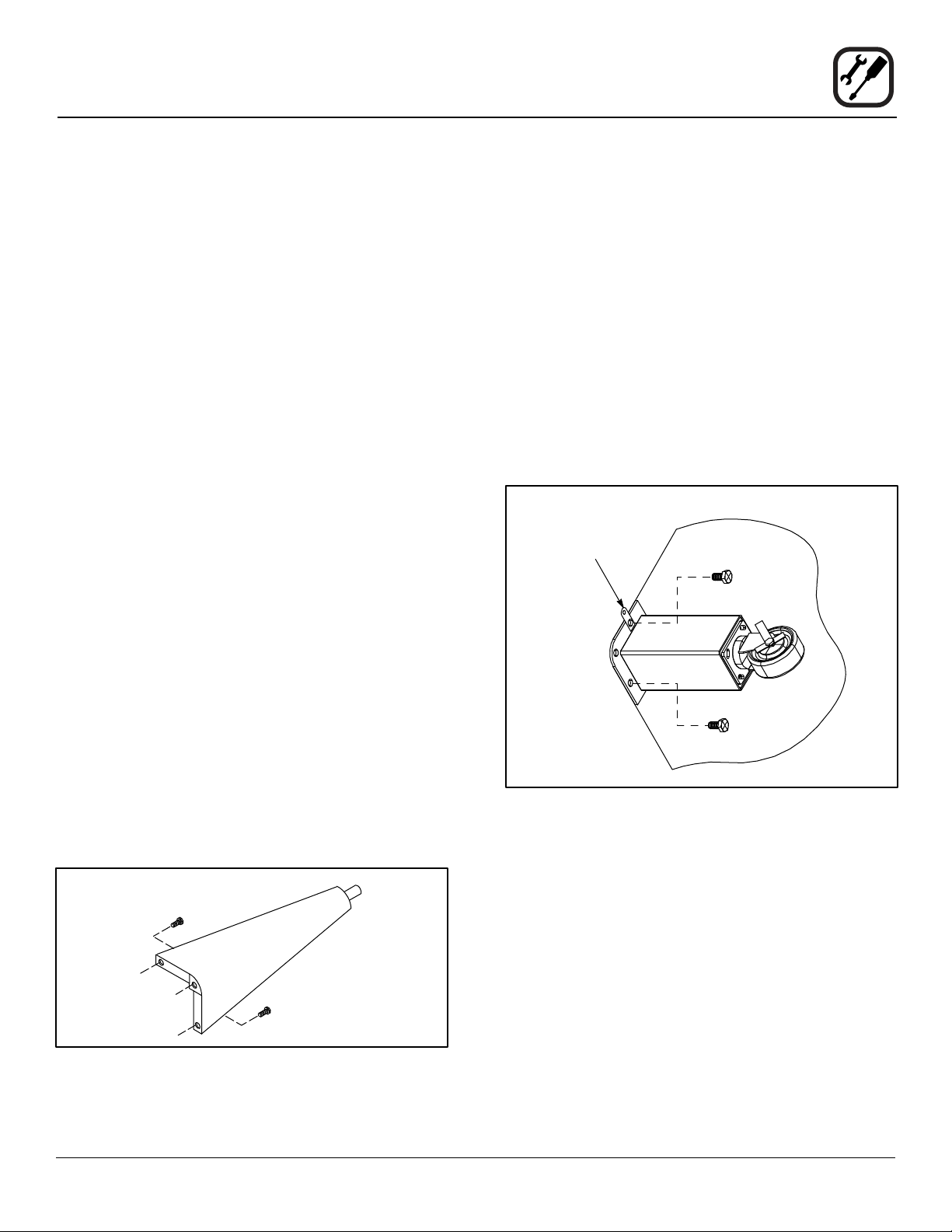
CASTER ATTACHMENT
1. Bolt supports to oven with 1/2-13 hex head bolts
(casters with brakes should be facing front of oven.)
2. Carefully place oven onto the casters. (It will be necessary to have several persons lift oven off the pallet
and set it onto the casters). Engage brakes on front
casters.
NOTE: A xed restraint must be provided if casters
are used in conjunction with a exible connector for movable appliances. This restraint
must secure the oven to a non-movable surface to eliminate stress on the connector. If
the oven is moved, the restraint must be reconnected after the oven is returned to it’s
normal position.
Restraint Cable
Bracket
• The top section of multiple section ovens will always
have the crown angle in position.
LEG ATTACHMENT
1. Put the oven onto a lift with the bottom of the oven
down.
2. Each leg is attached by two bolts to the underside of
the oven base frame.
Figure 2
Figure 3
5
Page 8

Installation
Oven Assembly
DOUBLE SECTION ASSEMBLY
1. Place lower section in predetermined place of installation.
2. Attach the legs (and casters if applicable) as previously described.
3. Using two 1” boards, place one near the edge of the
oven and the other at the far side of the ue collar.
4. Lift the upper section and place on the boards. Push
the top section across until the sections are even.
5. Remove the board from one side by placing a 2” x 4”
approximately four feet long under the angle frame.
Lift to remove the board.
6. Remove the other board in the same manner as
above, allowing the upper section to come gently to
rest in the proper position.
7. Install gas back-pipes and pressure regulator.
8. Install the canopy or direct type vent as appropriate.
9. Remove all tags.
10. Level the ovens side to side and front to back by placing a spirit level on the base frame of the lower section and screwing the adjustable leg feet in or out as
appropriate.
ULTRA ROKITE DECK
1. Slide the Ultra Rokite shelf through the door opening.
Rest the shelf on the deector and slide to the rear of
the oven until it drops into the shelf support.
2. Refer to pre-heating instructions supplied with Ultra
Rokite.
NOTE: Because of the weight of the Ultra Rokite shelves,
take care to avoid injury to yourself or damage to
the shelves when sliding sections into the oven.
NOTE: For model 981, Ultra Rokite is only available as a
bottom deck. DO NOT install the Ultra Rokite in
the top baking compartment of a 981.
Figure 4
6
Page 9

STEAM INJECTION
As an optional feature, all 900 Series ovens may be supplied with steam jets for baking hard rolls, and vienna,
french or other hard crusted breads. This item is also
available as a kit which may be installed in the eld. To
a baker, steam actually means an atmosphere of water
vapor. Therefore, it is very important that the steam be
low pressure (2-1/2 to 3 PSI), that condensate be taken
from the steam line before it enters the oven, and that the
steam be sufciently saturated to give the vapor cloud
effect required.
At least one quarter boiler horsepower for all large 900
Series compartment (42” x 32”) or two small 900 Series compartments (33” x 22”) is recommended. Several
rms manufacture electric and gas red steam generators ranging in size from 1/2 boiler horsepower upward.
If the steam generator is mounted adjacent to the oven,
line transmission losses will be insignicant. If the steam
source is located a considerable distance from the oven,
line transmission losses must be considered in determining the proper size of the steam. Please refer to the accompanying diagram for the recommended installation of
the steam injection system.
Installation
Oven Assembly
3/8” steam connection
on back of oven
3/8” pipe
1/2” riser
See Note 1
Pressure
gauge
See Note 2
1/2” riser
WARNING!!
Gas Flame in oven must be turned off when
steam is in use.
3/4” minimum
Boiler
Water level
Steam
separator,
make from
1/2” pipe,
12” long.
Hand operated valve
NOTES:
Pressure
reducing
valve
To drain
From steam
source
Trap
1. 3/8” Control Valve. Use dial type handle to obtain uniform
bake-to-bake results
2. Ideal steam condition at this valve, 2-3#PSI, 224-230 F.
Figure 5
7
Page 10

Installation
Ventilation
Blodgett gas deck ovens are direct red. Heat and ue
products from the burners are introduced directly into the
baking compartment. As a result, improper venting can
have a detrimental effect on the baking characteristics
of the oven. A properly designed ventilation system will
allow the oven to function properly, while removing unwanted vapors and products of combustion from the operating area.
This oven may be vented using either:
• A mechanically driven, canopy type, exhaust hood,
or
• A direct ue arrangement.
U.S. and Canadian installations
Refer to your local ventilation codes. In the absence of
local codes, refer to the National ventilation code titled,
“Standard for the Installation of Equipment for the Removal of Smoke and Grease Laden Vapors from Commercial
Cooking Equipment”, NFPA-96-Latest Edition.
General export installations
Installation must conform with Local and National instal-
lation standards. Local installation codes and/or requirements may vary. If you have any questions regarding the
proper installation and/or operation of your Blodgett oven,
please contact your local distributor. If you do not have a
local distributor, please call the Blodgett Oven Company
at 0011-802-658-6600.
The Blodgett Oven Company cannot assume responsibility for loss or damage suffered as a result of improper
installation..
CANOPY TYPE EXHAUST HOOD
A mechanically driven, canopy type exhaust hood is the
preferred method of ventilation.
The hood should be sized to completely cover the equipment plus an overhang of at least 6” (15 cm) on all sides
not adjacent to a wall. The distance from the oor to the
lower edge of the hood should not exceed 7’ (2.1m).
The capacity of the hood should be sized appropriately
with provisions for an adequate supply of make up air.
Capacity is generally expressed in ft3/min (CFM). 1 CFM
of natural gas burned with just enough air for complete
combustion produces 11 CFM of combustion products.
In virtually all appliances some excess air is used. This
volume of excess air is added to the ue products owing
from the appliance.
NOTE: Consult your local exhaust hood contractor for
your specic installation.
Installing the canopy hood draft diverter
Ovens ordered for hood venting are supplied with a draft
diverter. Install the draft diverter as follows:
1. Place the diverter over the ue connector with the
open area facing the front of the oven.
2. Secure both ends with the sheet metal screws provided.
Draft Diverter
WARNING:
Failure to properly vent the oven can be hazardous to the health of the operator and may
result in operational problems, unsatisfactory
baking and possible damage to the equipment.
Damage sustained as a direct result of improper ventilation will not be covered by the
Manufacturer’s warranty.
Front of Oven
Figure 6
8
Page 11

Installation
Ventilation
DIRECT FLUE ARRANGEMENT
When the installation of a mechanically driven exhaust
hood is impractical the oven may be vented by a direct
ue arrangement.
WARNING!!
It is essential that the direct ue be installed
as follows. Incorrect installation will result in
unsatisfactory baking and oven damage.
The ue must be class B or better with a diameter of 6”
(15 cm). The height of the ue should rise 6-8 ft (2-2.5 m)
above the roof of the building or any proximate structure.
Never direct vent the oven into a hood. The ue should be
capped with a UL Listed type vent cap to isolate the unit
from external environmental conditions.
The direct vent cannot replace air consumed and vented
by the oven. Provisions must be made to supply the room
with sufcient make-up air. To increase the supply air entering the room, a ventilation expert should be consulted.
Installing the draft hood
Ovens ordered for direct venting are supplied with a draft
hood. Install the draft hood as follows:
1. Place the draft hood over the ue connector.
VENTING PROBLEMS
Blodgett gas deck ovens use the natural principal of heat
rising as the basic method of ventilation. If the venting of
any deck oven is either restricted or forced in any way
the baking characteristics of the oven will be adversely
affected.
Examples of forced venting include:
• installation of a fan in a direct vent pipe
• use of a canopy type hood without the draft diverter
Examples of restricted venting include:
• use of tees and elbows
• long horizontal runs
2. Secure both ends with the sheet metal screws provided.
Flue
Draft Hood
Front of Oven
Figure 7
9
Page 12

Installation
Utility Connections - Standards and Codes
THE INSTALLATION INSTRUCTIONS CONTAINED
HEREIN ARE FOR THE USE OF QUALIFIED INSTALLATION AND SERVICE PERSONNEL ONLY. INSTALLATION OR SERVICE BY OTHER THAN QUALIFIED
PERSONNEL MAY RESULT IN DAMAGE TO THE OVEN
AND/OR INJURY TO THE OPERATOR.
Qualied installation personnel are individuals, a rm,
a corporation, or a company which either in person or
through a representative are engaged in, and responsible
for:
• the installation or replacement of gas piping and the
connection, installation, repair or servicing of equipment.
• the installation of electrical wiring from the electric
meter, main control box or service outlet to the electric appliance.
Qualied installation personnel must be experienced in
such work, familiar with all precautions required, and have
complied with all requirements of state or local authorities
having jurisdiction.
U.S. and Canadian installations
The installation must conform with local codes, or in the
absence of local codes, with the National Fuel Gas Code,
ANSI Z223.1/NFPA 54, or the Natural Gas and Propane
Installation Code, CSA B149.1, as applicable.
Installation must conform with local codes, or in the absence of local codes, with the National Electrical Code,
ANSI/NFPA 70-Latest Edition and/or Canadian National
Electric Code C22.1 as applicable.
Appliance is to be installed with backow prevention in
accordance with applicable federal, province and local
codes.
Australia and general export installations
Instllation must conform with Local and National instal-
lation standards. Local installation codes and/or requirements may vary. If you have any questions regarding the
proper installation and/or operation of your Blodgett oven,
please contact your local distributor. If you do not have a
local distributor, please call the Blodgett Oven Company
at 0011-802-658-6600.
10
Page 13

Installation
Gas Connection
GAS PIPING
A properly sized gas supply system is essential for maximum oven performance. Piping should be sized to provide a supply of gas sufcient to meet the maximum de-
mand of all appliances on the line without loss of pressure
at the equipment.
Example:
NOTE: BTU values in the following example are for natu-
ral gas.
You purchase a Model 911 deck oven to add to your existing cook line.
1. Add the BTU rating of your current appliances.
Pitco Fryer 120,000 BTU
6 Burner Range 60,000 BTU
Deck Oven 50,000 BTU
Total 230,000 BTU
2. Add the BTU rating of the new oven to the total.
Previous Total 230,000 BTU
911 20,000 BTU
New Total 250,000 BTU
3. Measure the distance from the gas meter to the cook
line. This is the pipe length. Let’s say the pipe length
is 40’ (12.2 m) and the pipe size is 1” (2.54 cm).
4. Use the appropriate table to determine the total capacity of your current gas piping.
The total capacity for this example is 320,000 BTU. Since
the total required gas pressure, 250,000 BTU is less than
320,000 BTU, the current gas piping will not have to be
increased.
NOTE: The BTU capacities given in the tables are
for straight pipe lengths only. Any elbows or
other ttings will decrease pipe capacities.
Contact your local gas supplier if you have
any questions.
Maximum Capacity of Iron Pipe in Cubic Feet of
Natural Gas Per Hour
(Pressure drop of 0.5 Inch W.C.)
PIPE
LENGTH (FT)
10 360 680 1400 2100 3950
20 250 465 950 1460 2750
30 200 375 770 1180 2200
40 170 320 660 990 1900
50 151 285 580 900 1680
60 138 260 530 810 1520
70 125 240 490 750 1400
80 118 220 460 690 1300
90 110 205 430 650 1220
100 103 195 400 620 1150
From the National Fuel Gas Code Part 10 Table 10-2
Maximum Capacity of Pipe in Thousands of
BTU/hr of Undiluted L.P. Gas at 11” W.C.
(Pressure drop of 0.5 Inch W.C.)
PIPE
LENGTH (FT)
10 608 1146 3525
20 418 788 2423
30 336 632 1946
40 287 541 1665
50 255 480 1476
60 231 435 1337
70 215 404 1241
80 198 372 1144
90 187 351 1079
100 175 330 1014
From the National Fuel Gas Code Part 10 Table 10-15
NOMINAL SIZE, INCHES
3/4” 1” 1-1/4” 1-1/2” 2”
OUTSIDE DIAMETER, INCHES
3/4” 1” 1-1/2”
11
Page 14

Installation
Gas Connection
PRESSURE REGULATION AND TESTING
900 Series ovens are rated from 20,000 to 50,000 BTU/
Hr. (6.4 to 14.6 kW/Hr.) per section. Each oven has been
adjusted at the factory to operate with the type of gas
specied on the rating plate.
1. Pull out control panel. The rating plate is attached to
the inside of the control compartment.
INLET PRESSURE
Natural Propane
Min Max Min Max
W.C. 7.0 10.5 11.0 13.0
kPa 1.43 2.61 2.74 3.23
MANIFOLD PRESSURE
Natural Propane
W.C. 5.0 10.0
kPa 1.24 2.49
• Inlet Pressure - the pressure of the gas before it
reaches the oven.
• Manifold Pressure - the pressure of the gas as it
enters the main burner(s).
Each oven is supplied with a regulator to maintain the
proper gas pressure. The regulator is essential to the
proper operation of the oven and must be installed. It is
preset to provide the oven with 3.5” W.C. (0.87 kPa) for
natural gas and 10.5” W.C. (2.50 kPa) for Propane at the
manifold.
DO NOT INSTALL AN ADDITIONAL REGULATOR
WHERE THE OVEN CONNECTS TO THE GAS SUPPLY.
Prior to connecting the oven, gas lines should be thor-
oughly purged of all metal lings, shavings, pipe dope,
and other debris. After connection, the oven should be
checked for correct gas pressure.
Installation must conform with local codes, or in the absence of local codes, with the National Fuel Gas Code,
NFPA54/ANSI Z223.1-Latest Edition, the Natural Gas Installation Code CAN/CGA-B149.1 or the Propane Installation Code, CAN/CGA-B149.2 as applicable.
The oven and its individual shutoff valve must be disconnected from the gas supply piping system during any
pressure testing of that system at test pressures in excess of 1/2 psig (3.45kPa).
The oven must be isolated from the gas supply piping
system by closing its individual manual shutoff valve during any pressure testing of the gas piping system at test
pressures equal or less than 1/2 psig (3.45kPa).
• Min - the minimum pressure recommended to operate the oven.
• Max - the maximum pressure at which the manufacturer warrants the oven’s operation.
12
Page 15

GAS HOSE RESTRAINT
If the oven is mounted on casters, a commercial exible
connector with a minimum of 3/4” (1.9 cm) inside diam-
eter must be used along with a quick connect device.
The restraint, supplied with the oven, must be used to limit
the movement of the unit so that no strain is placed upon
the exible connector. With the restraint fully stretched
the connector should be easy to install and quick connect.
The restraint (ie: heavy gauge cable) should be 1,000 lb.
(453 kg) test load and should be attached without damaging the building. DO NOT use the gas piping or electrical
conduit for the attachment of the permanent end of the
restraint! Use anchor bolts in concrete or cement block.
On wooden walls, drive hi test wood lag screws into the
studs of the wall.
1. Mount the supplied bracket to the leg bolt just below
the gas inlet.
2. The clip on restraining cable can be attached to the
mounting bracket.
Back of Oven
Restraint
Cable Bracket
Installation
Gas Connection
WARNING!!
If the restraint is disconnected for any reason it must be reconnected when the oven is
returned to its original position.
U.S. and Canadian installations
The connector must comply with the Standard for Connectors for Movable Gas Appliances, ANSI Z21.69 or
Connectors For Moveable Gas Appliances CAN/CGA-
6.16 and a quick disconnect device that complies with the
Standard for Quick-Disconnect Devices for Use With Gas
Fuel, ANSI Z21.41 or Quick Disconnect For Use With Gas
Fuel CAN 1-6.9. Adequate means must be provided to
limit the movement of the appliance without depending
on the connection and the quick disconnect device or its
associated piping. Adequate means must be provided to
limit the movement of the appliance without depending
on the connection and the quick disconnect device or its
associated piping.
General export installations
The restraint and quick connect must conform with Local and National installation standards. Local installation
codes and/or requirements may vary. If you have any
questions regarding the proper installation and/or opera-
tion of your Blodgett oven, please contact your local distributor. If you do not have a local distributor, please call
the Blodgett Oven Company at 0011-802-658-6600.
Double stacked unit shown. Use the same procedure for single
units with 25” (64 cm) legs.
Figure 8
13
Page 16

Installation
Initial Startup
ADJUSTMENTS ASSOCIATED WITH INITIAL INSTALLATION
Each oven, and its component parts, have been thoroughly tested and inspected prior to shipment. However, it is
often necessary to further test or adjust the oven as part
of a normal and proper installation. These adjustments
are the responsibility of the installer, or dealer. Since
these adjustments are not considered defects in material or workmanship, they are not covered by the Original
Equipment Warranty. They include, but are not limited to:
• calibration of the thermostat
• adjustment of the doors
• burner adjustments
• leveling
• testing of gas pressure
• tightening of fasteners
No installation should be considered complete without
proper inspection, and if necessary, adjustment by qualied installation or service personnel.
14
Page 17

Operation
Safety Information
The information contained in this section is provided for
the use of qualied operating personnel. Qualied operating personnel are those who have carefully read the information contained in this manual, are familiar with the
functions of the oven and/or have had previous experience with the operation of the equipment described. Adherence to the procedures recommended herein will assure the achievement of optimum performance and long,
trouble-free service.
Please take the time to read the following safety and operating instructions. They are the key to the successful
operation of your Blodgett oven.
SAFETY TIPS
For your safety read before operating
What to do if you smell gas:
• DO NOT try to light any appliance.
• DO NOT touch any electrical switches.
• Use an exterior phone to call your gas supplier immediately.
• If you cannot reach your gas supplier, call the re
department.
General safety tips:
• DO NOT use tools to turn off the gas control. If the
gas cannot be turned off manually do not try to re-
pair it. Call a qualied service technician.
• If the oven needs to be moved for any reason, the
gas must be turned off and disconnected from the
unit before removing the restraint cable. Reconnect
the restraint after the oven has been returned to its
original location.
Please take the time to read the following operating instructions. They are the key to the successful operation of
your Blodgett deck oven.
WARNING!!
In the event of a loss of pilot, allow a ve (5)
minute shut off period before attempting to
relight the oven.
15
Page 18

Operation
Oven Control
CONTROL DESCRIPTION
1. AUTOMATIC SAFETY PILOT VALVE - provides complete gas shut-off in the event of pilot failure.
2. MANUAL CONTROL VALVE - provides manual control of gas ow to the main burner through the thermostat.
3. THERMOSTAT - Provides regulation of oven temperature at setting selected by the oven operator.
OPERATION
Lighting
1. Turn the manual control valve (2) to OFF.
2. Push the red button on the automatic safety pilot
valve (1).
3. Apply a lighted match or taper to pilot burner.
4. After pilot burner lights, continue to depress red button for about 30 seconds and release.
5. Turn the manual control valve (2) to ON.
6. Set THERMOSTAT (3) to desired temperature.
Preheating
1. On initial startup, preheat the oven to 500ºF (260ºC)
two hours prior to loading and check oven periodically. This will allow paint to set properly.
Loading
• The deck is intended for cooking pizza and bread
products, other types of food may be cooked in pans
or containers.
• Load each baking shelf evenly.
• Do not allow pans to touch each other or sides of
oven.
• Do not load additional products after goods have
begun to bake.
• Open doors as seldom as possible.
• In two shelf ovens, load lower compartment rst.
To turn the oven off
1. Turn the manual control valve (2)
Figure 9
16
Page 19

Operation
Suggested Times and Temperatures
PRODUCT TEMPERATURE COOK TIME
Meats
Beef
Ribs
Rolled, boneless
Hip or rump, boneless
Veal
Bone-in cuts
Boned cuts
Lamb
Leg or shoulder
Shoulder, boned
Pork
Fresh bone-in cuts
Fresh boned cuts
Hams
Bacon
Sausages, links, patties
Meat pies, deep dish
Poultry (Weights are for unstuffed birds, for
stuffed, add 15 mins/lb)
Chickens, 2-3 lbs
Chickens, over 5 lbs
Chicken pies
Turkeys, 10-16 lbs
Turkeys, 25 lbs
Ducks
Geese
Fish
Fish, whole
Fish llets
Lobster
Oysters, casino
Oysters, devilled
Oysters, Rockefeller
NOTE: Actual times and temperatures may vary considerably from those shown above. They are affected by weight of
load, temperature of the product, recipe, type of pan and calibration of thermostat. Should your recipe vary, write
in your proven time and temperature for ready reference.
325ºF (165ºC)
325ºF (165ºC)
325ºF (165ºC)
325ºF (165ºC)
325ºF (165ºC)
325ºF (165ºC)
325ºF (165ºC)
350ºF (175ºC)
350ºF (175ºC)
325ºF (165ºC)
350ºF (175ºC)
350ºF (175ºC)
450ºF (230ºC)
350ºF (175ºC)
325ºF (165ºC)
450ºF (230ºC)
325ºF (165ºC)
325ºF (165ºC)
Same as chickens
Same as turkeys
350ºF (175ºC)
350ºF (175ºC)
400ºF (200ºC)
350ºF (175ºC)
350ºF (175ºC)
450ºF (230ºC)
rare - 16 mins/lb
med - 20 mins/lb
well - 25 mins/lb
add 10 mins/lb to above times
30 mins/lb
25 mins/lb
30 mins/lb
35 mins/lb
40 mins/lb
30-40 mins/lb
40-50 mins/lb
25-30 minss/lb
depends on degree of doneness
30 mins/lb
12-15 mins/lb
35 mins/lb
20-25 mins/lb
15-25 mins/lb
18-20 mins/lb
15-18 mins/lb
Same as chickens
Same as turkeys
15 mins/lb
15-20 mins/lb
Approximately 20 mins/lb
15 mins
15 mins
10 mins
17
Page 20

Operation
Suggested Times and Temperatures
PRODUCT TEMPERATURE COOK TIME
Baked Vegetables
Bananas
Boston Beans
Carrots
Egg plant
Macaroni
Stuffed peppers
Potatoes
Tomatoes
Cheese
Cheese fondue
Cheese loaf
Toasted cheese
Cheese soufe
Au gratin dishes
Breads
Bread, white, yeast
Raisin
Breads, rye
Rolls, standard white
Rolls, Parker House
Biscuits
Danish pastry
Desserts
Fresh fruit pie
Pies, precooked lling
Pie shells
Pies, custard
Cookies
Cheesecake, standard
Devil’s food
White layer cake
Baked apples
Fruit pudding
Indian pudding
Rice pudding
NOTE: Actual times and temperatures may vary considerably from those shown above. They are affected by weight of
load, temperature of the product, recipe, type of pan and calibration of thermostat. Should your recipe vary, write
in your proven time and temperature for ready reference.
350ºF (175ºC)
250ºF (120ºC)
400ºF (200ºC)
350ºF (175ºC)
350ºF (175ºC)
350ºF (175ºC)
400ºF (200ºC)
350ºF (175ºC)
350ºF (175ºC)
325ºF (165ºC)
350ºF (175ºC)
300ºF (150ºC)
450ºF (230ºC)
375-425ºF (230ºC)
400ºF (200ºC)
375ºF (190ºC)
375-400ºF (200ºC)
400-425ºF (200ºC)
375-400ºF (220ºC)
375-400ºF (200ºC)
375-400ºF (200ºC)
475ºF (245ºC)
400-450ºF (230ºC)
325-450ºF (230ºC)
400-475ºF (245ºC)
350ºF (175ºC)
360-375ºF (190ºC)
350-375ºF (190ºC)
400ºF (200ºC)
375ºF (190ºC)
325ºF (165ºC)
350ºF (175ºC)
15-20 mins/lb
8 hrs
Until tender
Until tender
15-25 mins/lb
25 mins/lb
45 - 1 1/2 hrs
15-20 mins/lb
40 mins/lb
40 mins/lb
15 mins/lb
20 mins/lb
Until browned
30-45 mins
40 mins
49-90 mins
20-45 mins
15-20 mins
15-25 mins
20-35 mins
50-60 mins
20-35 mins
15 mins
Depending upon mix
8-15 mins
40 mins
20-25 mins
20-35 mins
Approximately 1 hr
1 hr
3 hrs
variable
18
Page 21

Maintenance
Cleaning and Preventative Maintenance
CLEANING THE OVEN
Painted and stainless steel ovens may be kept clean and
in good condition with a light oil.
1. Saturate a cloth, and wipe the oven when it is cold.
2. Dry the oven with a clean cloth.
On the stainless front or interiors, deposits of baked on
splatter may be removed with any non-toxic industrial
stainless steel cleaner. Heat tint and heavy discoloration
may be removed with any non-toxic commercial oven
cleaner.
1. Apply cleaners when the oven is cold, and always rub
with the grain of the metal.
Clean Ultra Rokite decks with a triangular scraper used
for cleaning broiler grids. IMPORTANT - DO NOT use
water or any other liquids to clean the deck!
Clean the aluminized interior portion of the oven with a
mild detergent. DO NOT use caustic solutions such as
ammonia, lye or soda ash. DO NOT use domestic oven
cleaners. Any of these products will damage the aluminum coating.
Daily Cleaning
• Remove residue from beneath the doors with a small
broom or brush.
PREVENTATIVE MAINTENANCE
The best preventative maintenance measures are, the
proper installation of the equipment and a program for
routinely cleaning the ovens.
This oven requires no lubrication, however, the venting
system should be checked annually for possible deterio-
ration resulting from moisture and corrosive ue products.
If maintenance or repairs are required, contact the fac-
tory, the factory representative or a local Blodgett service
company.
Weekly Cleaning
• Brush out the combustion compartment and control
area.
• In addition to the daily cleaning it is necessary to
clean the air intakes on a weekly basis. Air intakes
provide necessary cooling air to the internal components. They are generally located on the rear and
sides of the equipment.
6 Month Cleaning
• Clean secondary air ducts and air entry ports.
NOTE: If the oven is moved the restraint must be recon-
nected after the unit is returned to it’s regular position.
19
Page 22

Maintenance
Troubleshooting Guide
POSSIBLE CAUSE(S) SUGGESTED REMEDY
SYMPTOM: Strong bottoms on the bakes
• Too much bottom heat
• Reduce cook temperature and increase time
• High gas pressure
• Faulty ue (strong direct vent)
• Product left in the oven too long
SYMPTOM: Uneven bakes
• Poor ventilation
• Oven doors left open too long
• Improper scaling of dough
• Fluctuating gas pressure
• Warped pans
SYMPTOM: Product burning
• Thermostat set too high
• Product left in the oven too long
• By-pass ame too high
• High gas pressure
• Thermostat out of calibration
• *
• *
• Shorten cook time
• *
• Do not open door unnecessarily
• Scale dough consistently
• *
• Change pans
• Reduce cook temperature
• Shorten cook time
• *
• *
• *
• Heat deectors worn out
SYMPTOM: Product dried out
• Oven temperature too low
• Not using enough water in the mix
• Thermostat out of calibration
• Faulty ue (strong direct vent)
SYMPTOM: Extended baking times
• Temperature setting too low
• Low gas pressure
• Strong ventilation
• Excessive door openings
*Denotes remedy is a difcult operation and should be performed by qualied personnel only. It is recommended, however, that All repairs and/or adjustments be done by your local Blodgett service agency and not by the owner/operator.
Blodgett cannot assume responsibility for damage as a result of servicing done by unqualied personnel.
• *
• Increase cook temperature
• Increase water in product mix
• *
• *
• Increase cook time
• *
• *
• Do not open door unnecessarily
20
 Loading...