

Blodgett 60G-KLT Service Manual

KLT-G Series
GAS TILTING FLOOR KETTLE
INSTALLATION - OPERATION - MAINTENANCE
BLODGETT OVEN COMPANY
www.blodgett.com
44 Lakeside Avenue, Burlington, Vermont 05401 USA
Manufacture Service Questions: 866-518-3977
PART NUMBER 170097 REV B (04/11)

THIS MANUAL MUST BE RETAINED FOR FUTURE REFERENCE. READ, UNDERSTAND
AND FOLLOW THE INSTRUCTIONS AND WARNINGS CONTAINED IN THIS MANUAL.
FOR YOUR SAFETY
DO NOT STORE OR USE GASOLINE OR OTHER FLAMMABLE VAPORS AND LIQUIDS IN
THE VICINITY OF THIS OR ANY OTHER APPLIANCE.
POST IN A PROMINENT LOCATION
INSTRUCTIONS TO BE FOLLOWED IN THE EVENT USER SMELLS GAS. THIS INFORMATION
SHALL BE OBTAINED BY CONSULTING YOUR LOCAL GAS SUPPLIER. AS A MINIMUM,
TURN OFF THE GAS AND CALL YOUR GAS COMPANY AND YOUR AUTHORIZED SERVICE
AGENT. EVACUATE ALL PERSONNEL FROM THE AREA.
WARNING
IMPROPER INSTALLATION, ADJUSTMENT, ALTERATION, SERVICE OR MAINTENANCE CAN
CAUSE PROPERTY DAMAGE, INJURY OR DEATH. READ THE INSTALLATION, OPERATING
AND MAINTENANCE INSTRUCTIONS THOROUGHLY BEFORE INSTALLING OR SERVICING
THIS EQUIPMENT.
NOTIFY CARRIER OF DAMAGE AT ONCE
IT IS THE RESPONSIBILITY OF THE CONSIGNEE TO INSPECT THE CONTAINER UPON
RECEIPT OF SAME AND TO DETERMINE THE POSSIBILITY OF ANY DAMAGE, INCLUDING
CONCEALED DAMAGE. WE SUGGEST THAT IF YOU ARE SUSPICIOUS OF DAMAGE TO
MAKE A NOTATION ON THE DELIVERY RECEIPT. IT WILL BE THE RESPONSIBILITY OF THE
CONSIGNEE TO FILE A CLAIM WITH THE CARRIER. WE RECOMMEND THAT YOU DO SO
AT ONCE.

IMPORTANT - READ FIRST - IMPORTANT
CAUTION: BE SURE ALL OPERATORS READ, UNDERSTAND AND FOLLOW THE OPERATING INSTRUCTIONS,
CAUTIONS, AND SAFETY INSTRUCTIONS CONTAINED IN THIS MANUAL.
WARNING: THIS UNIT IS INTENDED FOR USE IN THE COMMERCIAL HEATING, COOKING AND HOLDING OF
WATER AND FOOD PRODUCTS, PER THE INSTRUCTIONS CONTAINED IN THIS MANUAL. ANY
OTHER USE COULD RESULT IN SERIOUS PERSONAL INJURY OR DAMAGE TO THE EQUIPMENT
AND WILL VOID WARRANTY.
WARNING: KETTLE MUST BE INSTALLED BY PERSONNEL QUALIFIED TO WORK WITH ELECTRICITY AND
PLUMBING. IMPROPER INSTALLATION CAN RESULT IN INJURY TO PERSONNEL AND/OR
DAMAGE TO EQUIPMENT.
DANGER: ELECTRICALLY GROUND THE UNIT AT THE TERMINAL PROVIDED. FAILURE TO GROUND UNIT
COULD RESULT IN ELECTROCUTION AND DEATH.
WARNING: DO NOT CONNECT ANY PIPING TO THE POP SAFETY VALVE. THE VALVE MUST BE FREE TO VENT
STEAM AS NEEDED. THE ELBOW ATTACHED TO THE SAFETY VALVE SHOULD POINT TO THE
FLOOR. IMPROPER INSTALLATION WILL VOID WARRANTY.
WARNING: AVOID ALL DIRECT CONTACT WITH HOT EQUIPMENT SURFACES. DIRECT SKIN CONTACT COULD
RESULT IN SEVERE BURNS.
WARNING: AVOID ALL DIRECT CONTACT WITH HOT FOOD OR WATER IN THE KETTLE. DIRECT CONTACT
COULD RESULT IN SEVERE BURNS.
CAUTION: DO NOT OVER FILL THE KETTLE WHEN COOKING, HOLDING OR CLEANING. KEEP LIQUIDS
A MINIMUM OF 2-3” (5-8 CM) BELOW THE KETTLE BODY RIM TO ALLOW CLEARANCE FOR
STIRRING, BOILING AND SAFE PRODUCT TRANSFER.
WARNING: TAKE SPECIAL CARE TO AVOID CONTACT WITH HOT KETTLE BODY OR HOT PRODUCT WHEN
ADDING INGREDIENTS, STIRRING OR TRANSFERRING PRODUCT TO ANOTHER CONTAINER.
WARNING: WHEN TILTING KETTLE FOR PRODUCT TRANSFER:
1) USE CONTAINER DEEP ENOUGH TO CONTAIN AND MINIMIZE SPLASHING.
2) PLACE CONTAINER ON STABLE, FLAT SURFACE, AS CLOSE TO KETTLE AS POSSIBLE.
3) DO NOT OVER FILL CONTAINER. AVOID DIRECT SKIN CONTACT WITH HOT CONTAINER AND
ITS CONTENTS.
CAUTION: KEEP FLOORS IN FRONT OF KETTLE WORK AREA CLEAN AND DRY. IF SPILLS OCCUR, CLEAN
IMMEDIATELY, TO AVOID SLIPS OR FALLS.
WARNING: FAILURE TO CHECK SAFETY VALVE OPERATION PERIODICALLY COULD RESULT IN PERSONAL
INJURY AND/OR DAMAGE TO EQUIPMENT.
WARNING: WHEN TESTING SAFETY VALVE, AVOID ANY EXPOSURE TO THE STEAM BLOWING OUT OF THE
SAFETY VALVE. DIRECT CONTACT WITH STEAM COULD RESULT IN SEVERE BURNS.
WARNING: TO AVOID INJURY, READ AND FOLLOW ALL PRECAUTIONS STATED ON THE LABEL OF THE
WATER TREATMENT COMPOUND.
WARNING: BEFORE REPLACING ANY PARTS, DISCONNECT THE UNIT FROM THE ELECTRIC POWER SUPPLY
AND CLOSE THE MAIN GAS VALVE. ALLOW FIVE MINUTES FOR UNBURNED GAS TO VENT.
OM-KLT-G 1

IMPORTANT - READ FIRST - IMPORTANT
WARNING: KEEP WATER AND SOLUTIONS OUT OF CONTROLS AND ELECTRICAL EQUIPMENT. NEVER SPRAY
OR HOSE THE SUPPORT HOUSING OR ELECTRICAL CONNECTIONS.
CAUTION: MOST CLEANERS ARE HARMFUL TO THE SKIN, EYES, MUCOUS MEMBRANES AND CLOTHING.
PRECAUTIONS SHOULD BE TAKEN. WEAR RUBBER GLOVES, GOGGLES OR FACE SHIELD AND
PROTECTIVE CLOTHING. CAREFULLY READ THE WARNINGS AND FOLLOW THE DIRECTIONS ON
THE LABEL OF THE CLEANER TO BE USED.
CAUTION: USE OF ANY REPLACEMENT PARTS OTHER THAN THOSE SUPPLIED BY THE MANUFACTURER
OR AN AUTHORIZED SERVICE AGENT CAN CAUSE OPERATOR INJURY AND DAMAGE TO THE
EQUIPMENT, AND WILL VOID ALL WARRANTIES.
IMPORTANT: SERVICE PERFORMED BY OTHER THAN FACTORY AUTHORIZED PERSONNEL WILL VOID
WARRANTIES.
WARNING: DO NOT HEAT AN EMPTY KETTLE. EXCESSIVE STEAM PRESSURE COULD DEVELOP.
2 OM-KLT-G

Table of Contents
Important Operator Warnings .....................................................page 1-2
References..................................................................................... page 3
Equipment Description.................................................................. page 4
Inspection and Unpacking ............................................................ page 5
Installation ................................................................................... page 6-7
Operation ................................................................................ page 8-10
Sequence of Operation ................................................................ page 11
Cleaning.................................................................................. page 12-13
Maintenance........................................................................... page 14-16
Troubleshooting...................................................................... page 17-18
Parts Lists............................................................................... page 19-27
Service Log ................................................................................. page 28
References
CSA INTERNATIONAL
8501 East Pleasant Valley Road
Cleveland, Ohio 44131
NSF INTERNATIONAL
798 N. Dixboro Rd.
P.O. Box 130140
Ann Arbor, Michigan 48113-0140
AMERICAN NATIONAL STANDARDS INST., Inc.
1430 Broadway
New York, New York 10018
Z223.1-1984 - National Fuel Gas Code
Z21.30 - Installation Gas Appliances & Piping
KLENZADE SALES CENTER ECOLAB, Inc.
370 Wabasha
St. Paul, Minnesota 55102
NATIONAL FIRE PROTECTION ASSOCIATION
60 Battery March Park
Quincy, Massachusetts 02269
NFPA/54 -Installation Gas Appliances & Piping
NFPA/70 - The National Electric Code
ZEP MANUFACTURING COMPANY
1310-T Seaboard Industrial Boulevard
Atlanta, Georgia 30318
OM-KLT-G 3

Equipment Description
The Blodgett KLT-G is a floor-mounted, tilting, steam jacketed kettle with a
thermostatically controlled, self-contained, gas-heated steam source and appropriate
controls, mounted on a sturdy base. The kettle is available in 20, 40, 60 or 80 gallon
capacities.
The body of the kettle is constructed of stainless steel, welded into one solid piece.
The kettle is furnished with a reinforced rim and a butterfly shaped pouring lip. It has a
steam jacket which is ASME shop inspected and registered with the national board for
working pressures up to 50 PSI. Kettle finish is 180 emery grit on the inside and bright
high buff polish on the outside.
The kettle is tilted with a hand crank to pour out its contents. Stainless steel panels
enclose the controls and the base. Four stainless steel tubular legs support the unit.
Bullet or flanged feet on each of the legs can be adjusted to level the kettle. Optional
feature can include a two inch tangent draw-off valve.
The self-contained steam source is heated by propane or natural gas. Ignition is
electronic.
The kettle is charged at the factory with chemically pure water which contains rust
inhibitors. The steam source provides kettle temperatures of 150º to approximately
295ºF (65 to 150ºC). Unit controls include a thermostat, pressure gauge, safety valve,
pressure limit control, low water cut-off, power switch and gas regulator valve. The
gas supply shuts off automatically when the kettle is tilted.
4 OM-KLT-G
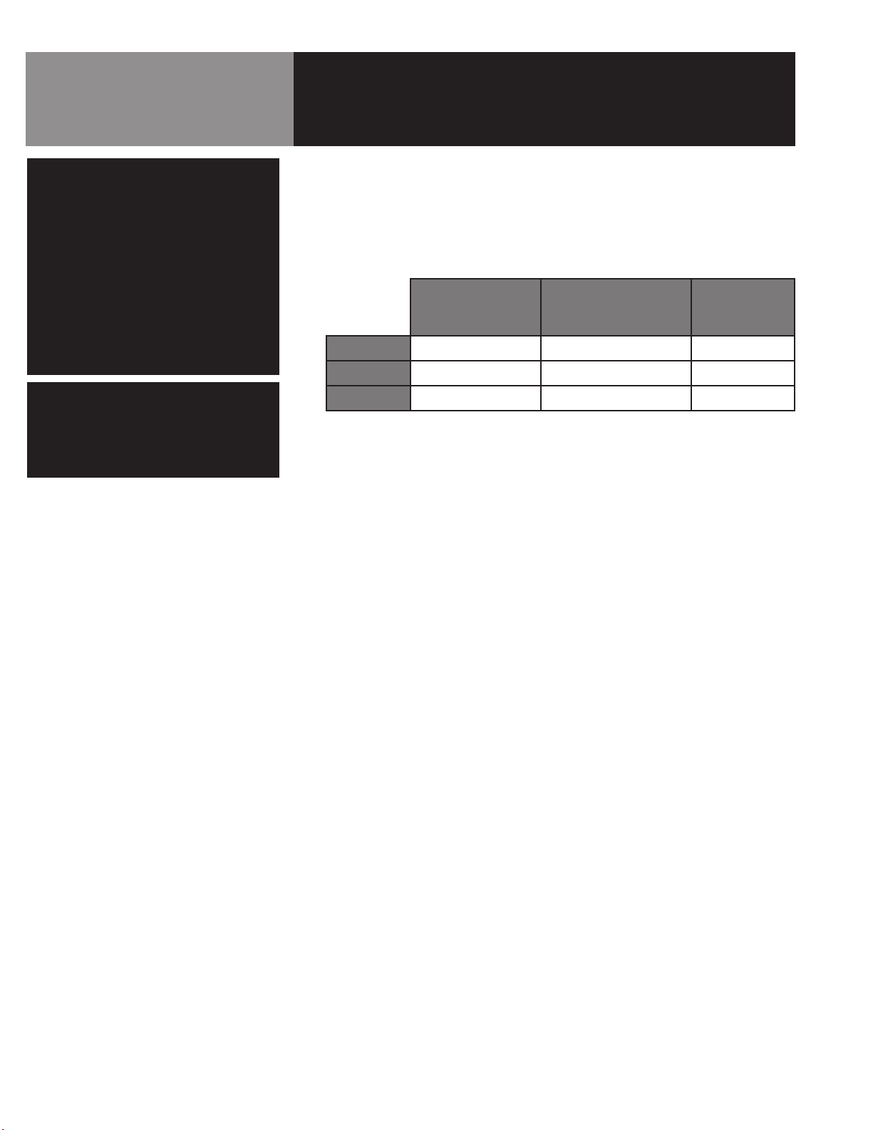
The unit must be specified for use with natural or propane gas. Service connections
for gas and electricity are required. Standard power supply is 115 Volt. Alternate
voltages (208V or 240V) are available.
Model 20G-KLT 40G-KLT 60G-KLT 80G-KLT
Kettle Capacity
Jacket Capacity
Kettle Body
Inside Diameter
Base - Width
Base Front to Back
Firing Rate /hr
Energy into
Product /hr
20 gallons
(75 liters)
2-1/2 gallons 3-1/2 gallons 4 gallons 1-1/4 gallons
20 inches
(508 mm)
35 inches
(889 mm)
28 inches
(736 mm)
72,000 BTU 100,000 BTU 150,000 BTU 150,000 BTU
44,140 BTU 65,000 BTU 93,000 BTU 93,000 BTU
40 gallons
(150 liters)
26 inches
(660 mm)
47 inches
(1194 mm)
29 inches
(736 mm)
60 gallons
(225 liters)
30 inches
(762 mm)
47 inches
(1194 mm)
29 inches
(736 mm)
80 gallons
(300 liters)
34 inches
(863 mm)
52 inches
(1320 mm)
37-1.2 inches
(952 mm)
Options available with listed models are:
1. Two inch tangent drawoff
2. Strainers, solid disk, 1/4 or 1/8 inch holes
3. Lift-off cover
4. Counterbalanced cover w/actuator
5. Basket Inserts
6. Water fill faucets with swing spout
7. Kettle Brush Kit
Inspection & Unpacking
CAUTION
SHIPPING STRAPS ARE UNDER TENSION
AND CAN SNAP BACK WHEN CUT. TAKE
CARE TO AVOID PERSONAL INJURY OR
DAMAGE TO THE UNIT BY STAPLES LEFT
IN THE WALLS OF THE CARTON.
CAUTION
THIS UNIT WEIGHS BETWEEN 535 AND
978 POUNDS (245 TO 400 Kg) DEPENDING
ON SIZE. INSTALLER SHOULD USE
PROPER EQUIPMENT TO LIFT SAFELY.
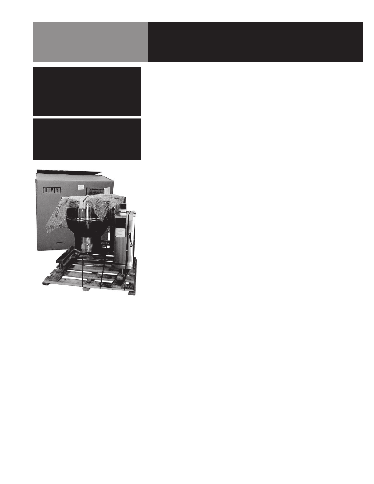
The unit will arrive in a heavy shipping carton and will be bolted or banded to a skid.
Immediately upon receipt, inspect the carton carefully for exterior damage.
Carefully cut any polyester straps around the carton and detach the sides of the box from
the skid. Pull the carton up off the unit. Thoroughly inspect the unit for hidden damage.
Report any shipping damage or incorrect shipments to the delivery agent.
Write down the model number, serial number, and installation date, and retain this
information for future reference. Space for these entries is provided at the top of the
Service Log at the back of this manual. Keep this manual on file and available for
operators to use.
When installation is to begin, carefully cut any straps which hold the unit on the skid. Lift
the unit straight up off the skid. Examine packing materials to be sure loose parts are not
discarded with the materials.
OM-KLT-G 5
Installation
WARNING
THE UNIT MUST BE INSTALLED BY
PERSONNEL WHO ARE QUALIFIED TO WORK
WITH GAS, ELECTRICITY AND PLUMBING.
IMPROPER INSTALLATION CAN
CAUSE INJURY TO PERSONNEL AND/OR
DAMAGE TO THE EQUIPMENT. THE UNIT
MUST BE INSTALLED IN ACCORDANCE WITH
APPLICABLE CODES. THE UNIT MUST BE
INSTALLED BY A LICENSED PLUMBER
OR GAS FITTER WHEN INSTALLED WITHIN
THE COMMONWEALTH OF MASSACHUSETTS.
DANGER
ELECTRICALLY GROUND THE UNIT AT
THE TERMINAL PROVIDED. FAILURE
TO GROUND UNIT COULD RESULT IN
ELECTROCUTION AND DEATH.
For efficient performance the kettle must be installed in a well-ventilated area. Items
which might restrict or obstruct the flow of air for combustion and ventilation must be
removed. The area directly around the appliance must be free of combustible materials.
1. Installation can be on a combustible or noncombustible floor. Clearances should
be per table below.
Model
Left Side
Right Side
Rear
Minimum
Clearance from
Combustible walls
6 in. 0 in. 6 in.
6 in. 0 in. 10 in.
10 in. 10 in. 12 in.
Minimum
Clearance from
Non-Combustible walls
Recommended
Clearances
2. The kettle should be installed in an adequately ventilated room with provision
for adequate air supply. The ventilation must employ a vent hood and exhaust
fan with no direct connection between the vent duct and the kettle flue. Do not
obstruct the flue or vent duct after installation.
3. Set the kettle in place and level it using a spirit level on the bar rim, by turning
the bullet or flange feet to adjust leg length. Allow clearance around the unit for
cleaning, maintenance and service.
4. Complete the piping to the gas service main with ½” line or approved equivalent.
5. For standard units, provide 115 vac, 60 Hz, single phase 5 AMP electrical
service. The unit may also be ordered for alternate electric service of 208 VAC or
240 VAC. Observe local codes and/or The National Electrical Code in accordance
with ANSI/NFPA 70 (current edition), or the Canadian Electrical Code, CSA C22.2
(current edition), as applicable. Use the wiring diagram inside the service panel
and at the rear of this manual
6. Bring electrical service through the entrance at the rear of the support housing
with a ½ inch conduit connector. Make a watertight connection with the
incoming lines.
7. Electrically ground the unit at the terminal provided.
8. After the kettle has been connected to the gas supply, check all gas joints for
leaks. DO NOT USE FLAME TO CHECK FOR LEAKS. A thick soap solution or other
suitable leak detector should be employed.
6 OM-KLT-G
Installation
WARNING
DO NOT CONNECT ANY PIPING TO
THE PRESSURE RELIEF VALVE. THE VALVE
MUST BE FREE TO VENT STEAM AS
NEEDED. IMPROPER INSTALLATION
WILL VOID THE WARRANTY! THE ELBOW
ATTACHED TO THE PRESSURE RELIEF
VALVE MUST POINT TO THE FLOOR.
WARNING
DO NOT STAND ON OR APPLY
UNNECESSARY WEIGHT OR PRESSURE ON
THE KETTLE FRONT OR POURING LIP. THIS
COULD RESULT IN THE OVERLOAD AND
FAILURE OF THE TILT MECHANISM, AND
POSSIBLE SERIOUS INJURY AND BURNS TO
THE OPERATOR AND OTHERS.
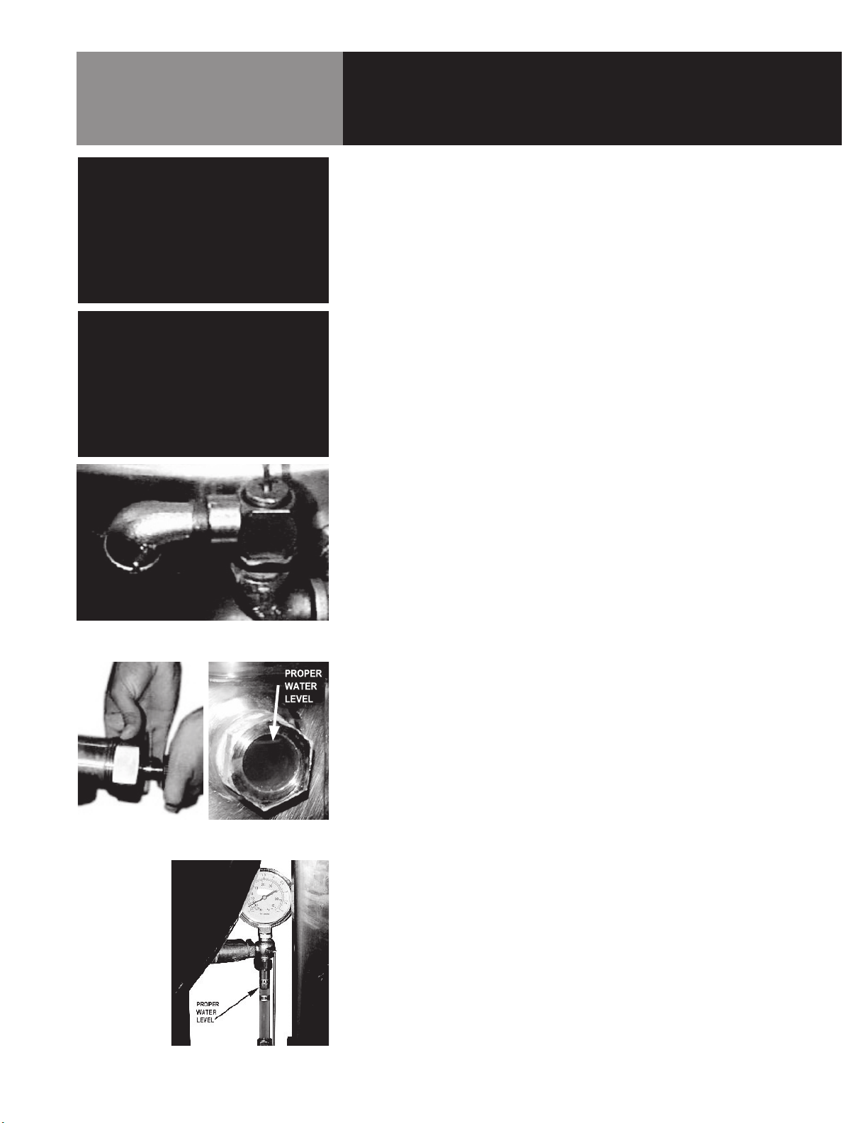
The open end of the pressure relief
valve elbow must face downward.
9. The gas supply and unit’s installation must conform with local codes or in the
absence of local codes, with the National Fuel Gas Code, ANSI Z223.1/NFPA
54 (current edition), or the Natural Gas and Propane Installation Code CSA
149.1(current edition), as applicable. Additionally following must be complied
with: THE AREA DIRECTLY AROUND THE APPLIANCE MUST BE CLEARED OF
ALL COMBUSTIBLE MATERIAL. FAILURE TO FOLLOW THESE INSTRUCTIONS
CAN CAUSE BODILY INJURY AND /OR PROPERTY DAMAGE. The appliance and
its individual shut-off valve must be disconnected from the gas supply piping
system during any testing at pressures in excess of ½ PSI (3.45 kPa). The
appliance must be isolated from the gas supply piping system by closing its
individual manual shut-off valve during any pressure testing at or less than ½
PSI (3.45 kPa).
10. Confirm that the jacket water level is between the gauge glass markers or inside
the sight glass port. If the level is low, follow instructions under “Jacket Filling
and Water Treatment,” Page 16.
11. The open end of the elbow on the outlet of the safety valve must face downward.
If it does not, turn it to the correct position.
12. For units with optional tangent draw-off, assemble the tangent draw-off by
placing the large nut over the draw-off valve and inserting it into the draw-off
tube. ONLY HAND-TIGHTEN THE NUT to complete installation.
13. Now that the kettle has been installed, you should test to ensure that it is
operating correctly.
a. Remove literature and packing materials from inside and outside of the
unit.
b. If the unit is equipped with a draw-off valve (product outlet), clean out any
material which might clog or damage the draw-off.
When attaching the draw-off
valve hand tighten the nut.
Each day confirm the jacket water
level by checking the water gauge.
c. Confirm that the tilting mechanism is operating properly by tilting the kettle
through its full range. Then return the kettle to the upright position.
e. Turn on the electrical service to the unit.
f. Pour 1-2 quarts of water into the kettle.
g. Following “To Start Kettle” instructions in the “Operation” section (Page
9), begin heating the water at the highest thermostat setting. The heat
indicator light should come on, and heating should continue until the boils.
14. If the unit functions as described it is ready for use. If it does not function as
described, contact your local Authorized Service Agency.
OM-KLT-G 7
Operation
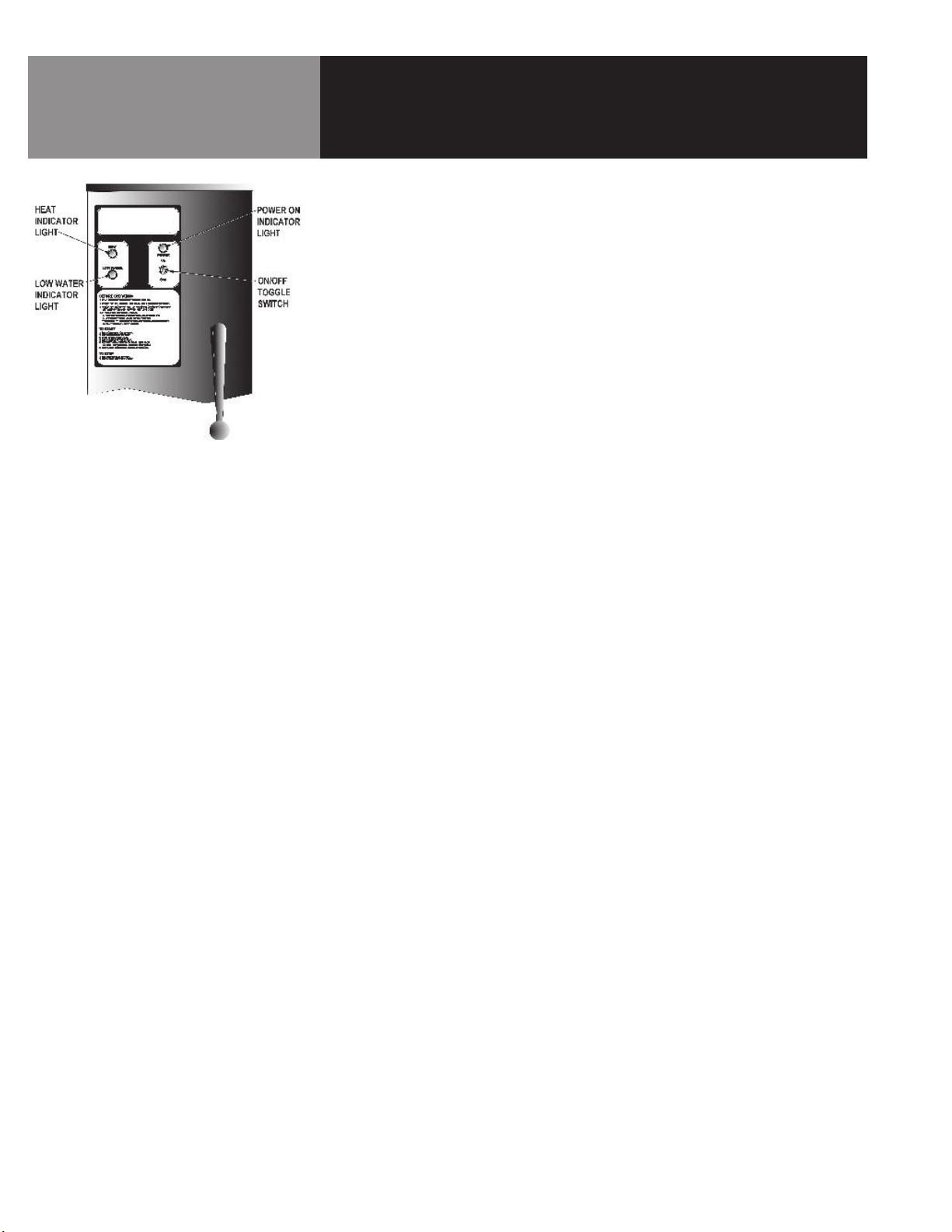
A. Controls
Operator controls for the kettle are:
1. Manual gas valve (on gas line behind the unit), which controls the supply
of gas from the main to the unit.
2. On-Off (Toggle) Switch. This controls the supply of electric power to the
control circuits.
3. Thermostat dial, which turns the thermostat on or off, and sets the kettle
temperature.
4. Tilting crank, used to tilt the kettle body.
5. Indicator Lights to alert operator of unit conditions:
a. Power On Indicator - shows that the unit is turned on
b. Heat Indicator - indicates that main gas is on to produce steam in
the kettle jacket.
c. Low Water indicator - shows that jacket water is low
6. Unit gas pressure regulator adjustment - located behind the access door
in the kettle skirt.
B. Operating Procedure
1. To Start Kettle:
a. EVERY DAY make sure that the jacket water level is between the
markers on the gauge glass or inside the sight glass port. If the level
is too low, see “Jacket Filling and Water Treatment” on page 16.
b. Check the pressure gauge. If the gauge does not show 20 to 30
inches of mercury (Hg) vacuum (that is a reading of 20 to 30
below 0 atmospheric pressure), see “Jacket Vacuum” on page 16.
c. Do not attempt to light any burner with a flame. Turn the manual
gas valve ON (align handle with gas line).
1) Turn toggle (on-off) switch ON. The electronic ignition will
attempt to light the pilot for 90 seconds, or until it is lit.
Once lit, proceed to step two.
2) Turn thermostat to desired setting. The main gas burner will
ignite, and will cycle to maintain the set temperature. The
3) If the unit does not light, turn it off and wait five minutes.
Then follow the instructions again.
2. To Empty Kettle:
a. To tilt the body of the kettle forward, turn the hand crank on the
front of the cabinet counter-clockwise. The body will stay in the
position it holds when you stop cranking. To return the kettle body
to its upright position, turn the crank clockwise.
8 OM-KLT-G
b. Product may also be transferred by means of the optional draw-off
valve, if the kettle is so equipped.
 Loading...