

Page 1
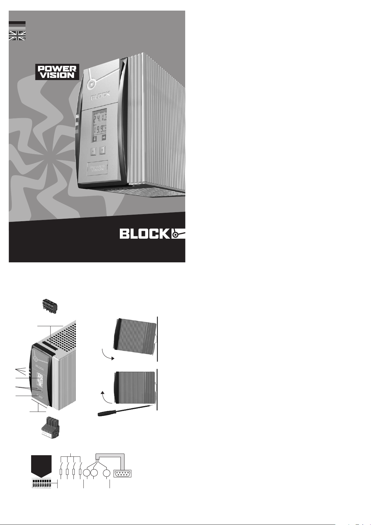
PVSB 400
Stabilisierte Stromversorgung
mit integrierter Kontrolleinheit
Stabilised power supply
wi t h in t e g rated cont r o l mo dule
KAPVSB400 2015•12
block.eu
Installation
Installation
Sicherheitsmaßnahmen vor der
Installation
Das Betriebsmittel ist vor unzulässiger
Beanspruchung zu schützen. Insbesondere dürfen bei Transport und Handhabung
keine Bauelemente verbogen und/oder
Isolationsabstände verändert werden.
Die Berührung elektrischer Bauelemente und Kontakte ist zu vermeiden.
Da s Be t r iebsm i t t e l immer im sp annungsfreien Zustand montieren und
verdrahten. Die Produktbeschreibung
und die technischen Hinweise in unserem
Hauptkatalog sowie die Aufschriften am
Betriebsmittel und auf dem Typenschild
sind zu beachten.
Installation
Die Installation ist entsprechend den
örtlichen Gegebenheiten, einschlägigen
Vorschriften (z. B. VDE 0100), nationalen
Un f a l lverhü t u n gsvor s c h rif t e n (z . B. UV VVBG4 bzw. BGV A3) und den anerkannten
Regeln der Technik durchzuführen. Dieses
el e k t r i sche Betri e b smittel ist ei n e Komponente, die zum Einbau in elektrische
Anlagen oder Maschinen bestimmt
ist und erfüllt die Anforderungen der
Niederspannungsrichtlinie (2014/35/
EU). Um eine ausreichende Konvektion zu
gewährleisten, sind folgende Mindestabstände zu benachbarten Modulen
empfohlen: 40mm oben und unten,
10mm auf der linken und rechten Seite.
Bei Einbau in Maschinen ist die Aufnahme
des bestimmungsgemäßen Betriebes
solange untersagt, bis festgest ellt wurde,
dass die Maschine den Bestimmungen
der Maschinenrichtlinie (2006/42/EG)
entspricht.
EN 60204 ist zu beachten. Die Aufnahme
des bestimmungsgemäßen Betriebes
ist nur bei Einhaltung der EMV-Richtlinie
(2014/30/EU) erlaubt. Die Einhaltung der
durch die EMV-Gesetzgebung geforderten Grenzwerte liegt in der Verantwortung des Herstellers der Anlage oder
Maschine.
Safety measures before installation
This equipment is to be protected against
improper use. Components are not to
be be n t or isol a t i on spac i n g chan g e d , especially through handling and transport.
The contact with electrical components
and terminals is to be avoided. Always
disconnect the equipment from the mains
supply, before commencing installation or
wiring. The product description, technical
information in our main catalogue and the
marking on the equipment ratings plate
ar e to be ob served.
Installation
In s t a llat i o n must be car r i e d out accor ding to the prevailing local conditions
and safety regulations (e.g. VDE 0100)
national accident prevention regulations
(e . g . UV V -VBG4 or BGV A3 ) and the generally accepted rules of technology. This
equipment is a component designed for
installation into electrical systems and
machines, and fulfils the requirements of
the low voltage guidelines (2014/35/EU).
In order to ensure sufficient convection,
fol l o w instal l a tion cle a r ances is re c o m mend: 40mm on top and bottom, 10mm
on the left and right side. When installed
into machinery, the normal operation is
forbidden until it is determined that the
machine fulfils the requirements of the
machinery guidelines (2006/42/EG).
EN 60204 must be observed. The EMC
requirements must be fulfilled before
operation is commenced. The observance
of the required limitations for the EMC
legislation
(2014/30/EU) is the responsibility of
the manufacturer of the installation or
machinery.
Anschluss
Um Verwechslungen mit anderen Anschlüssen zu vermeiden, verwenden Sie
T
ausschließlich die mitgelieferten Stecker.
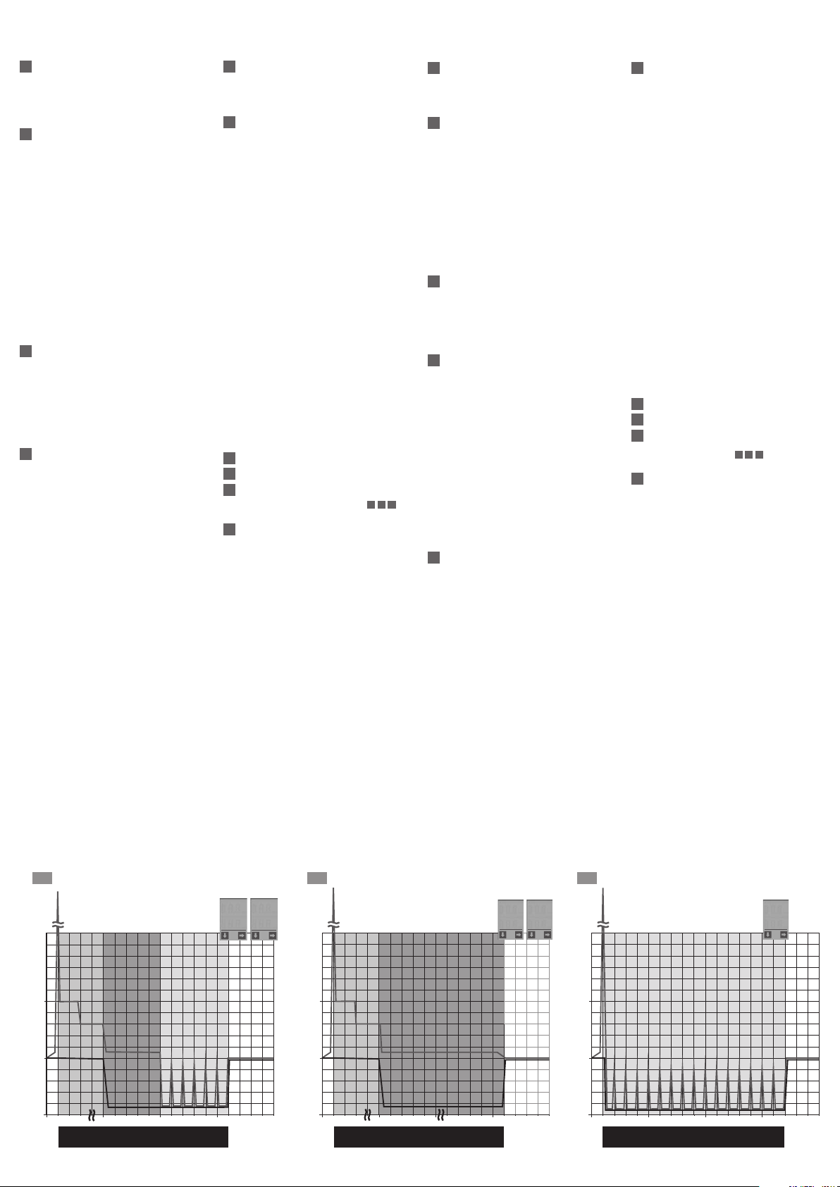
Ab b i ldun g ze igt den PVSB 40 0 /24 - 2 0
Thi s fi gure sh o w s th e PV SB 400/ 24-20
Eingang
line
PE L1 L2 L3
4
c
1
b
a
2
3
8
+ + – –
Ausgang
5
load
U
out
optionales
8
Zubehör
optional
accessory
S1 S2 S3 S4
RxPC TxPC
12345678
S1: geschlossen, wenn Betriebsstundensignalgeber erreicht
cl ose d, if a t le ast one ch an ne l tri ppe d
S2 : of fen , wen n F eh le r auf tri tt ope n, if a fau lt ha s oc cur r ed
S3 : ge sch lo sse n, we nn War nun g au ftr itt clo se d, if a wa rn in g occ urr s
S4: geschlo ssen, wen n Uout < Power Good clo sed , if Uo ut < Po we r Goo d
Connection
To re duce th e risk of mi sta king th e
terminals, the supplied terminals must
T
be used.
6
T
U
out
Pi n 2 = RxP C
Pi n 3 = TxPC
Pi n 5 = GND
DIN 35 mm
rail
LED: Die grüne LED (a) leuchtet,
1
sofern die Ausgangsspannung größer
als ca. 20,4 Vdc (veränderbarer, werkseitiger Power Good Grenzwert ) ist.
Die gelbe LED (b) zeigt Warnungen an.
Di e ro t e LE D (c ) zeigt Fe h l e r an.
Display der Kontrolleinheit: Das
2
Einstellen und Parametrisieren des
Gerätes über das Display wird auf der
Rückseite erklärt.
Tas ten: Linke Taste = vorwärts im
Me n ü , rechte Tast e = zu m Parame trisieren.
Eingang (schwarzer Stecker) line
4
Ausgang (blau e r St e cker) load
5
Montage: Setzen Sie das PVSB mit
de r Tra gschi e n enführ u n g an die Ob e r ka n t e der Trags c h iene an un d rasten
Si e es nach un t e n ei n .
Demontage: Ziehen Sie den
7
Schnappriegel mit Hilfe eines
Schraubendrehers auf und hängen
Sie das Modul an der Unterkante der
Tragschiene aus.
Schnittstelle und Signalausgänge:
Die Schutzkappe ist zur Vermeidung
statischer Entladungen nur unter
Anwendung von ESD-Schutzmaßnahmen abzunehmen. 14 Frei belegbare
Ausgänge, konfigurierbar per PC mit
CONFI POWERVISION, 1 Betriebs-
stundensignalgeber (werkseitige
Be l e gung) , 2 Fehler, 3 Warnung,
4 Power Good (werkseitige Belegung),
568 Kommunikationsein- und Aus-
gä n ge, 7 Ausgangsspannung.
Die Schnit tstelle ist nicht galvanisch
getrennt. Ein geeignetes Adapterkabel (PV-KOK2) oder den passenden
Stecker (PV-CON) können Sie optional
über BLOCK beziehen. Bei Anschluss
eines Relais an einen Signalausgang
muss zwingend eine Freilaufdiode
vorhanden sein.
LED: The green LED (a) lights as soon
1
as the output voltage is larger than
approx. 20.4 Vdc (changeable, factory
set Power Good level). The yellow LED
(b) shows a warning condition. The red
LE D (c ) sh ows a fau l t co nditio n .
Th e contro l unit dis p lay: The para-
2
meter adjustments are described on
the ba c k of this le a f l e t .
Buttons: Left button = forward in
3
the me n u, righ t bu t t o n = to al t e r parameter settings.
Input (black plug) line
4
Output (blue plug) loa d
5
Mounting: Place the PVSB with the
6
DIN rail guide on the upper edge of the
DIN rail, and snap it in with a
downward motion.
Removing: Pull the snap lever open
7
with the aid of a screwdriver and slide
the module out at the lower edge of
the DI N rail.
In t erface an d outpu t signal por t:
8
The protective cap is to reduce the
risk of static discharge and should
on l y be removed wi t h th e use of ESD
protective measures. Free output
connections that can be configured
pe r PC wi t h CO NFI POWER V I S I ON,
op e r a t iona l ti me elap s e (f act ory set),
fault, warning,
Po w e r Go od (fac tor y se t ), communi c a t i on inp u t and outpu t , outpu t
voltage.
The in t e r f a c e has no ga l v anic se p aration and should be only connected with
a suitable adapter cable (PV-KOK2)
or the plug (PV-CON) which both are
available from BLOCK . If a relay is to
be connected to a signal output then it
is imperative that a free running diode
be us e d.
Page 2
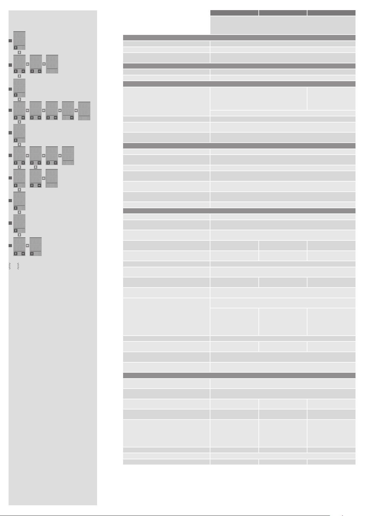
Einstellen und Parametrisieren über das Display
A = mit di e se m Be feh l ( li nke Tast e) ko m me n Sie zu m nä chs t en Me nüp unk t
1
Standardanzeige
Zeigt die aktuelle Ausgangsspannung und
den aktuellen Ausgangsstrom an. Nach
einer Parameteränderung wird automatis c h diese Da r s t e llun g ge w ählt .
2
Ausgangsspannung einstellen
Da s Displa y zeigt di e ak t u e lle Au s g angs spannung an. Das Ändern der Spannung
ist durch Betätigen der linken Taste
möglich. Die Spannung kann entweder bis
zum unteren Spannungslimit verringert
werden oder bis zum oberen Spannungslimit erhöht werden. Nachdem das
jeweilige Spannungslimit erreicht wurde,
dreht sich die Richtung der Spannungsänderung um.
A = Ausgangsspannung schrittweise
verändern
B = Ausgangsspannung speichern
Der gespeicherte Spannungswert stellt
sich nach jedem Einschalten des Gerätes
automatisch wieder ein.
3
Betriebsstundenzähler
Der Betriebsstundensignalgeber zeigt an,
nach welchem Intervall der zugehörige
Signalausgang für eine Sekunde von
0 Vo l t auf die Au sgan g s span n ung um schaltet. Die Umschaltung erfolgt
zyklisch alle eingestellten Betriebsstunden.
4
Betriebsstundensignalgeber
Der Betriebsstundensignalgeber zeigt
an, zu welchem Zeitpunkt der zugehörige
Signalausgang für 1 Sekunde von 0 Volt
auf die Ausgangsspannung umschaltet.
Eingestellter Standardwert: 5000 h
B = Betriebsstundensignalgeber einstellen
Betriebsstundensignalgeber einstellen
A = Einstellen der Tausender-Stunden
(kh)
B = Bestätigen der Tausender-Stunden
(kh)
A = Einstellen der Stunden
B = Bestätig e n de r St unde n
B = Bestätig e n Einstell u ng
5
Betriebsstunden-Countdown
Anzeige der verbleibenden Stunden bis
das Betriebsstunden-Signal am Ausgang
generiert wird.
6
Überstromverhalten
Es wi r d angezei g t , we l ches Üb e r s t r o mverhalten eingestellt ist. Es können drei
Modi parametrisiert werden.
B = Überstromverhalten einstellen
Überstromverhalten einstellen
A = zw ische n Ko nstantstrom - M o dus un d
Fuse-Mode (Hiccup) wechseln
B = Konstantstrom-Modus speichern
und zur Konstantstromzeit wechseln
I.Co = Konstantstrom-Modus
I.Fu = Fuse-Mode (Hiccup)
A = Zei t fü r den Kons t a n t s t r o m Modus in
Se k u nden (c a . 110 % I
Wechsel in den Fuse-Mode
B = Konstantstromzeit speichern
I. t = Ko nstant strom z e i t
00 0 s = unbegr e n z t
Modus 1: begrenzte Konstantstromzeit
mit anschließendem Fuse-Mode (Hiccup)
(siehe 6.1)
Modus 2: unbegrenzte Konstantstromzeit (siehe 6.2)
Mo d us 3: Fu s e - Mode (Hi c c up), für mi nimale Ausgangsenergie. (siehe 6.3)
7
Minimale Ausgangsspannung
8
Maximale Ausgangsspannung
9
Maximaler Ausgangsstrom
Zum Rücksetzen der Werte für
be i d e Tasten für 5 Se k u nden be t ä t i g en.
10
Fehlermanager
Anhand des Fehlercodes (siehe auch
Typenschild am Gehäuse) kann anhand
der blinkenden Segmente, eine Fehleranalyse vorgenommen werden.
Der letzte Fehler wird fest gespeichert,
so dass auch noch nach einem Neustart
des PVSB 400 eine Fehlerursache detektiert werden kann.
B = letzten Fehler anzeigen
NENN
) bis zum
7 8 9
Setting the parameters using the display
A = pres s in g the le ft bu t t on me a ns mo ve to ne x t men u p oi n t
1
Standard display
Sh o w s the actual ou t p u t voltag e an d current. This display is always shown after
changing any parameter settings.
2
Output voltage setting
The display shows the actual output
voltage. The voltage can be changed by
pressing the left button. The voltage can
be changed to either the upper or lower
level settings, after reaching one limit
setting the direction will automatically
reverse.
A = chan g e s output vo l t a ge st ep by step
B = save th e ou t put voltag e se t t i ng
Switching on the power supply, the saved
se t t i n g wi ll au t om a t icall y be re s e t .
3
Operational hours counter
This display shows at which time the
related signal output switched from 0 V
to the set output voltage for one second.
This switching is periodical in dependence
of the ad justed cou n t e r.
4
Operational time counter
This display shows at which time the
related signal output switched from 0 V
to the se t ou t put volt ag e .
Fa c t ory stan d ard se t t i ng: 50 00 h
B = set the op e r a t iona l ti m e count er
Setting the operational time counter
A = adj u s t ing the tho u sand ho u r set t ing
(kh)
B = confirm th e th o usan d ho ur settin g
(kh)
A = adj u s t ing the ho u r set t ing
B = confirm th e ho ur setting
B = confirm al l the setting s
5
Operational hours countdown
Displays the remaining time for the
operational hours signal to be generated
at th e ou t put .
6
Overload current behaviour
This displays what overload condition is
presently set. There are three paramet er
settings possible.
B = over l o a d curren t se t t i n g
Setting the overload current
A = switch betwee n co n s t ant cur r e n t
an d fu se mode
B = save co n s t ant curr e n t mo de and
ch a nge to cons t a n t current tim e
I.Co = constant current mode
I.Fu = fuse mode
A = Tim e se t t i ng to chan g e fr o m the
const ant current mode in seconds
(a p p r ox. 110 % I
mode.
B = save co n s t ant curr e n t se t t i ng
I. t = co nstant cu r r e n t time set tin g
00 0 s = unlim i t e d
Mode 1: limited constant current until
sw i t c h i ng to fuse mo d e (s ee 6.1 )
Mode 2: unlimited constant current (see
6.2)
Mo d e 3: fuse mo d e (see 6.3 )
7
Min. output voltage
8
Max. output voltage
9
Max. output current
To res e t th e value s fo r
bu t t o n s fo r 5 second s .
10
Fault manager
A fault analysis can be made according to
the blinking segments of the display (see
rating plate on housing).
The la s t faul t sy m p t om will be au t o matically saved, so that even after a new
start of the PVSB 400 a fault analyse can
be ma de.
B = show la s t faul t di splay
rated
7 8 9
) to the fuse
press bo t h
[V]
out
U
X x Inenn
X x Irated
Inenn
Irated
Unenn
Urated
6.1
Top
Boost
[%]
I
out
Top Boost
NENN + 60 A
I
Power
Boost
Konstantstromzeit
(005=5 Sek)
constant current
time (005 s=5 sec)
Überstromphase
Overcurrent phase
Fuse Mode
SET
Iout
I.Co
005
Iout
I.t
t [sec]0
6.2
Top Boost
Top
NENN + 60 A
I
Boost
s
[V]
U
X x Inenn
X x Irated
Inenn
Irated
Unenn
Urated
out
[%]
out
I
Power
Boost
Konstantstromzeit
(000 s=unbegrenzt)
constant current time
(000 s=unlimited)
Überstromphase
Overcurrent phase
SET
Iout
I.Co
000
Iout
I.t
t [sec]0
6.3
Top Boost
Top
NENN + 60 A
I
Boost
s
[V]
out
U
X x Inenn
X x Irated
Inenn
Irated
Unenn
Urated
[%]
out
I
Fuse Mode
Überstromphase
Overcurrent phase
SET
Iout
I.Fu
t [sec]0
Page 3
Uout
23.9
Vdc
Iout
1
9,76
Adc
Uout
Uout
23.9
25,5
Vdc
Iout
2
9,76
Adc
log
kh
001
h
3
979
logtime
kh
003
4
h
297
time
kh
003
5
h
297
FU
Iout
6
I.Co
Uo.L
7
22,5
Uo.H
8
26,7
Io.H
9
27.5
Err
10
!!!
Segment blinkt
Segment blinks
Uo Ausgangsspannung
output voltage
STO
store
SET
setting
FU Überstrommodus
overload current behaviour
I.Co Konstantstrommodus
const ant current mode
I.Fu
fuse mode
I.t Konstantstromzeit
const ant current time
Uo.H max. Ausgangsspannung
max. ou tput voltage
Uo.L min. Ausgangsspannung
min. output vo ltage
I.Hi max. Ausgangsstrom
max. ou tput c urren t
Err Fehlermanager
fault manager
STO
Vdc
SET
Uo
logtime
logtime
kh
SET
297
005
Iout
I.t
STO
I.Fu
003
h
297
s
STO
I.Co
003
SET
SET
Iout
I.Co
SET
I.Fu
Err
!$!
Einstellungen gespeichert
Einstellungen vornehmen
Fuse mode (Hiccup)
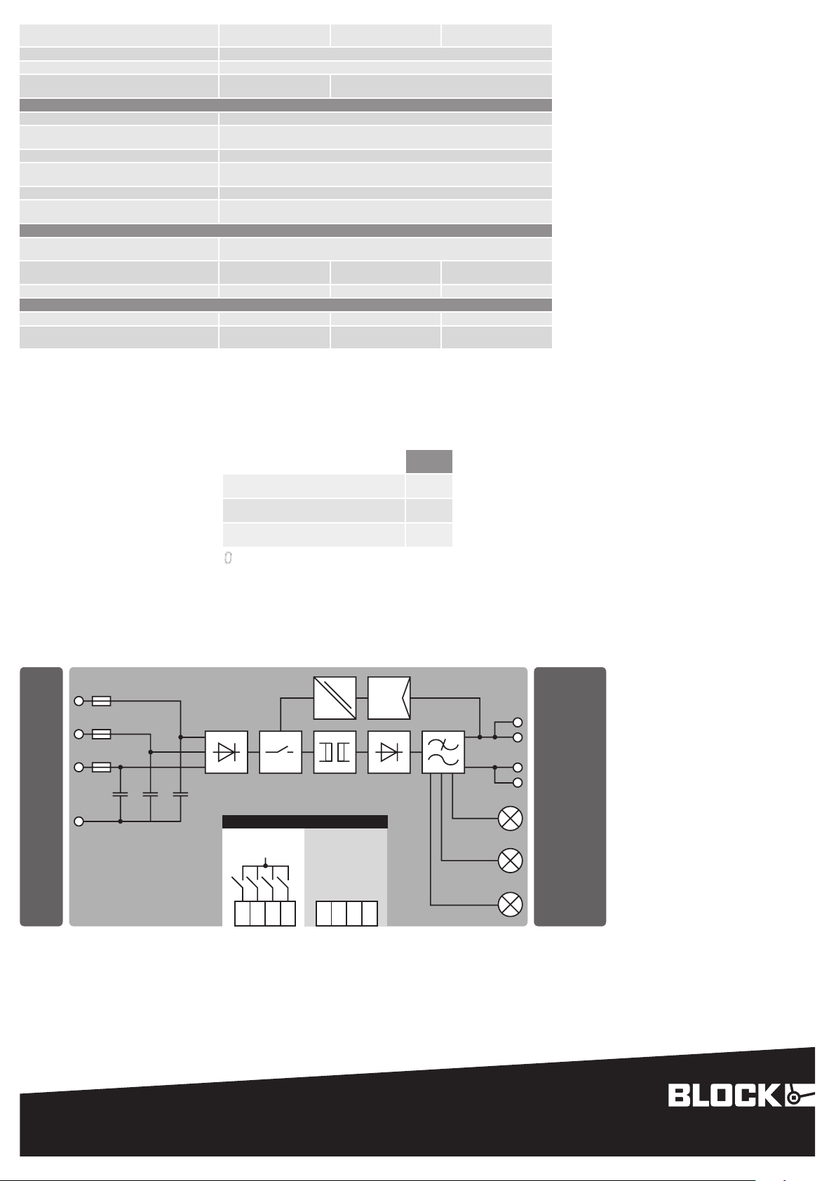
Technische Da ten
Technical details
No rme n Safety standards
Sicherheit Safety EN 60 95 0 , UL 60 95 0 , UL 50 8
EM V EMC EN 6120 4 -3 (P rod ukt nor m ) EN 612 0 4- 3 (pr o du ct st and ar d)
Schutzkleinspannung
Sa fet y ext r a-l ow vo lta ge
Zulassungen Approvals
UL UL UL /CS A 609 50 re c ogn i se d
UL UL UL 508 li s ted / CS A 22 .2 No .1 07.1 3r d Ed. list ed
Um wel t Environment
logtime
kh
STO
h
Umgebungstemperatur
Ambient temperature
Lagertemperatur Storage temperature –2 5 … +85° C
Kühlart Cooling
Zulässige Luftfeuchtigkeit
Allowable humidity
Si che rhe it un d Schut z Safety and protection
Prüfspannung HV t est vo lta ge 4242 Vdc
Ba uar t
Construction
Schutzart Protection index IP 20 (na c h EN 60 52 9 ) IP 20 (t o EN 60 52 9 )
Schutzklasse
Safety class
Anschlusskabel
Conductors
Einsatzbereich
Installation
Rückspeisungsfestigkeit Feedback voltage ma x . 35 Vd c
Eingangsdaten Input
Eingangsnennspannung Rated input voltage 3/2 x 400 – 500 Vac
Eingangsspannungsbereich
Operating input voltage range
Nennfrequenzbereich
Ra t ed fr equ e nc y ran ge
Ei nga n gs n en nst r om be i 3x3 4 0 Va c
Ra t ed in p ut cu rre nt at 3x 34 0 Vac
Ei nga n gs n en nst r om be i 2x3 40 Vac
Ra t ed in p ut cu rre nt at 2x 34 0 Vac
Einschaltstrom (kalt) In-r ush cur ren t ( col d ) <3 0 A p
Optionale aktive Einschaltstrombegrenzung
Ac tiv e i n- rus h cur r ent li mi ter, op t ion al
Eingangssicherung intern
Internal fuse
Externe Absicherung (UL-konform)
External protection device (UL-recognised)
Empfohlene externe Absicherung*
Recommended external protection*
Ableitstrom Leakage current ty p. 1 mA
Ne t z au s f al l üb erb rüc k un g bei 40 0 / 500 Vac
Ma ins dr op co m pe nsa tio n a t 40 0 / 500 Va c
Überspannungsschutz
Over voltage protection
Anschlüsse: WAGO Multisteckersystem
Ter m in als: WAG O mul ti pl u g sy ste m
Ausgangsdaten Output
Ausgangsnennspannung
Ra t ed ou t put vo lta ge
Ausgangsspannungsbereich
Ra t ed ou t put vo lta ge ra ng e
Ausgangsnennstrom bei 24 Vdc
Ra t ed ou t put cu rre n t at 24 Vdc
Po w er Bo o st (b e i Bet rie b v on 3 Ei ng angsp has e n)
Po w er Bo o st (i f ope rat ion wi th 3 in put ph as e s)
Ma x im al zu e nt neh men d er Au sg ang ss tro m be i
Betr ieb von nur 2 Eingangspha sen
(Dauerhaft/Power Boost)
maximum output current allo wed if only opera ted wit h
2 in put ph as es
(continuously/Power Boost)
Top Bo ost Top Bo o st 70 Adc 80 Adc 100 Adc
Strombegrenzung Current limitation ty p. 1, 1 x I
Wirkungsgrad Efficiency ty p. 91 ,7 % ty p. 92 ,9 % t yp . 93, 6 %
PVSB 400/24-10 PV SB 40 0/ 24- 20 PVSB 400/24- 40
Schaltnetzteil, dreiphasige, primär get akt ete Einb austromve rsor gung
Primary switched mode supply, three phase primar y switched mode power supply
–2 5 … +70 ° C, De r at ing : -3 %/ K > +50 ° C
An l au f bei -4 0° C typ g ep rüf t De vic e sta r t at -40 ° C ty pe- tes t e d
Selbstkühlung durch natürliche Konvektion bei vertikaler Einbaulage
0, 6 Aa c (24 Vdc /10 Adc) 1,1 Aac (2 4 Vd c /2 0 Adc ) 2,0 Aac (24 Vdc/40 Ad c)
1, 2 Aac (24 Vdc /10 Ad c) 2, 1 Aac (2 4 Vd c /20 Adc) 2, 6 Aa c (24 Vdc /4 0 A dc )
3 x 2, 5 AT 3 x 2, 5 AT 3 x 3, 2 AT
3 x Le i tun g ss c hu tzs cha lte r 6 A, 10 A oder 16 A , Ch a ra kte ris t ik B, C
Motorschutzschalter
Ei nst ell w er t 1,6 A
Ei nst ell ber eic h 1,6 – 2,5 A
Motor protection switch
Se tti n g va l ue 1. 6 A
Ad jus t men t ran ge 1. 6 – 2. 5 A
22 ,6 / 51,5 ms 13 , 2 / 36 , 8 ms 15 ,6 / 42 ,9 ms
10 Adc 20 Adc 40 Ad c
20 Adc / 4 s (1 5 Ad c / 8 s) 40 Ad c / 4 s (3 0 Adc / 8 s) 60 Ad c / 4 s (5 0 Adc / 16 s)
20 Adc / 4 s 25 Adc / 4 s 40 Adc / 4 s
für TH35-Tragschienenmontage
co m po nen t f or mo un tin g on DI N 35 mm ra il s
EN 60 95 0 ( SE LV) un d EN 60 20 4 (PE LV )
EN 60 95 0 ( SE LV) an d EN 60 20 4 (PE LV )
De r at ing : -5 %/ K > +45 ° C
400 ... 500 Vac,
Derat ing: -0,5 Adc/10 Vac >
AN (N atu r al ai r c on v ect ion co ol i ng )
5 bi s 96 % re lat i ve Fe uch t e , ke ine B eta u un g zuläs s ig
5 to 96 % rela t i ve hu mi dit y w ith no dew
gekaps elt, für den Einbau im Schalts chran k
enclosed for installation in switching cabinets
vo r be rei t e t für Ge rä te un d A nl a ge n der Schu t z kl ass e I
Zu m A ns chl us s Kup fer k ab el mi t mi n. 75 °C vew e nd en.
pr e pa red fo r sa fet y cla ss I
Us e C op p er Co n du c t or s onl y, ra t ed 75 °C .
Ei nsa t z in Ber e ich e n mi t Ver sc hmu t zu n gs gra d 2
For installation in Pollution Degree 2 environment
340 – 550 Vac (480 – 780 Vdc)
50 – 60 H z
typ. wie Eingangsnennstrom
ty p. as rate d inp ut cu r ren t
nicht erforderlich
not necessary
3 x Ci r cu it br e ak e rs 6 A, 10 A o r 16 A
Motorschutzschalter
Ei nst ell w er t 2,5 A
Ei nst ell ber eic h 2, 5 – 4,0 A
Motor protection switch
Se tti n g va l ue 2. 5 A
Ad jus t men t ran ge 2. 5 – 4.0 A
du r ch Vari s t or im Pr im ä rs tro m kre is
th r oug h v ar i sto r in pr im a ry ci r cui t
WAG O Ser i e 23 1, ma x 2 ,5 mm ²
WAG O ser ies 231 , max . 2.5 mm ²
24 Vd c ±1 %
22 ,8 – 28 ,8 Vd c
t y p. 1. 1 x I
nenn
Motorschutzschalter
Ei nst ell ber eic h 2, 5 – 4,0 A
Motor protection switch
Ad jus t men t ran ge 2. 5 – 4.0 A
rated
Ei nst ell w er t 3,2 A
Se tti n g va l ue 3. 2 A
–25 … +55° C,
44 0 Vac
Page 4
m ax . V er l us t le i st u ng Le e rl a uf / N en nl a s t
ma x . P ow er lo ss id lin g / n om i na l loa d
Restwelligkeit Residual ripple <7 0 mV p p
Parallelschaltbarkeit Parallel operation ja, zur Leistungserhöhung ye s , for in cr eas ed po w er
Anschlüsse: WAGO Multisteckersystem
Ter m in als: WAG O mul ti pl u g sy ste m
Signalisierung Signaling
LED rot LED re d Fehler, z.B. U
LED gelb (konfigurierbar)
LED yellow (configurabl e)
LED grün LED gr e en U
Aktive Schaltausgänge (konfigurierbar)
Active switched outputs (configurable)
Schni tts tell e Int e r fa ce RS 232
Anschlüsse: WAGO Multisteckersystem
Ter m in als: WAG O mul ti pl u g sy ste m
Mechanische Daten Mechanical data
Be fes t igu ng
Mounting
Maße B x H x T ***
Dimens ions widt h x height x depth ***
Gewicht Weight 1, 0 k g 1, 3 kg 2, 5 k g
Bestellnummern Order numbers
Standard standard PVSB 400/24-10 PVSB 400/24-20 PVSB 400/24-40
mit aktiver Einschaltstrombegrenzung
Ac tiv e i n- rus h cur r ent li mi ter, op t ion al
* Für DC Eingangsspannung ist eine geeignete DC-Sicherung erforderlich.
* For DC input voltage suitable DC fuse required.
** WAGO Serie 831: Mit Aderendhülse max 6 mm
** WAGO Series 831: With ferrule max. 6 mm
*** Maße ohne Anschlussstecker, Tiefe T ab Oberkante Tragschiene.
*** Dimensions without terminals, depth T from upper edge of DIN rail.
2
. Bei feindrähtigen Leitern bitte geeigneten Spleißschutz verwenden.
2
. Please use suitable anti-splaying method for fine-stranded conductors.
7,8 / 19, 9 W 8, 3 / 3 4, 1 W 7,0 / 61, 5 W
Se r ie 231 ma x . 2 ,5 mm ²
se r ie s 231 ma x. 2. 5 m m²
< Powe r Goo d: LE D le uch t et Fau l t e.g . U
out
Wa rn ung , z.B . I
> = Po w er Go o d: LE D le u ch tet U
out
57 x 127 x 179 mm 7 7 x 12 7 x 179 mm 12 8 x 127 x 205 mm
PVSB 400/24-10B PVSB 400/24-20B PVSB 400/24-40B
Wa rn ing e.g . I
Se r ie 73 3 ma x. 0, 5 mm²
serie s 733 max. 0.5 mm²
Tragschienenmontage mit zwei Montagemöglichkeiten
ra i l mo u nt ing wi th tw o pos sib l e va r ie tie s
Serie 831 max. 10,0 mm² **
serie s 831 max. 10.0 mm² **
: LE D l eu cht e t
> I
nenn
out
> I
out
rated
out
24 Vd c/max . 25 mA
< Powe r Goo d: LE D li g hts
out
: LE D l ig h t s
> = Po w er Go o d: LE D li g ht s
Fehler/Warnungen
Faults/warnings
Diese Fehler oder Warnungen können von der
Stromversorgung detektiert werden und über
die Signalausgänge oder über die Schnittst elle
ausgew ert et werde n. Auch am Gerät selbs t lässt
sich eine Fehlerdiagnose durch den Fehlermanager
durchführen.
These faults or warnings can be detect ed by the
power supply, to be evaluate d through the signal
outpu t inter face . Also direc tly on the unit, faults can
be diag n os ed wi t h the he lp of th e fau l t ma n ag e r.
Funktionsschaltbild
Functional diagram
L1 (+)
L2
L3 (-)
PE
Anzeige
Display
Gerätefehler
Hardware fault
Au sga ngs s tro m zu ho ch (I
to o hi g h (I
I
out
Au sga ngs s pa n nu n g un ter Po wer Go od We r t*
Po w er go o d fa ilu re *
Segment blinkt segment blinks
*nur über externe Software veränderbar (werkseitig: 20,4 Vdc)
*w ith ex ter nal So f t war e mod ifi a bl e onl y (fa c t or y set tin g: 20 .4 Vd c)
> I
out
rated
> I
)
nenn
out
)
&!!
!&!
!'!
optional
Signal outputs
RS-232
+24V
+
+
–
–
LED (Green):
DC OK
LED (Yellow):
WARNING
S1 S2 S3 S4
1 52 63 74 8
BLOCK Transformatoren-Elektronik GmbH
Max-Planck-Straße 36-46 . 27283 Verden, Germany
[email protected] . block.eu
RxPC
TxPC
+24V
0V
LED (Red):
ERROR
Technische Änderungen vorbehalten.
Subject to change.
block.eu
 Loading...