

Page 1
PC-1AC/DC24
Primär getaktetes Schaltnetzteil, Power Compact
Primary switched mode power supply, Power Compact
Alimentation à découpage primaire, Power Compact
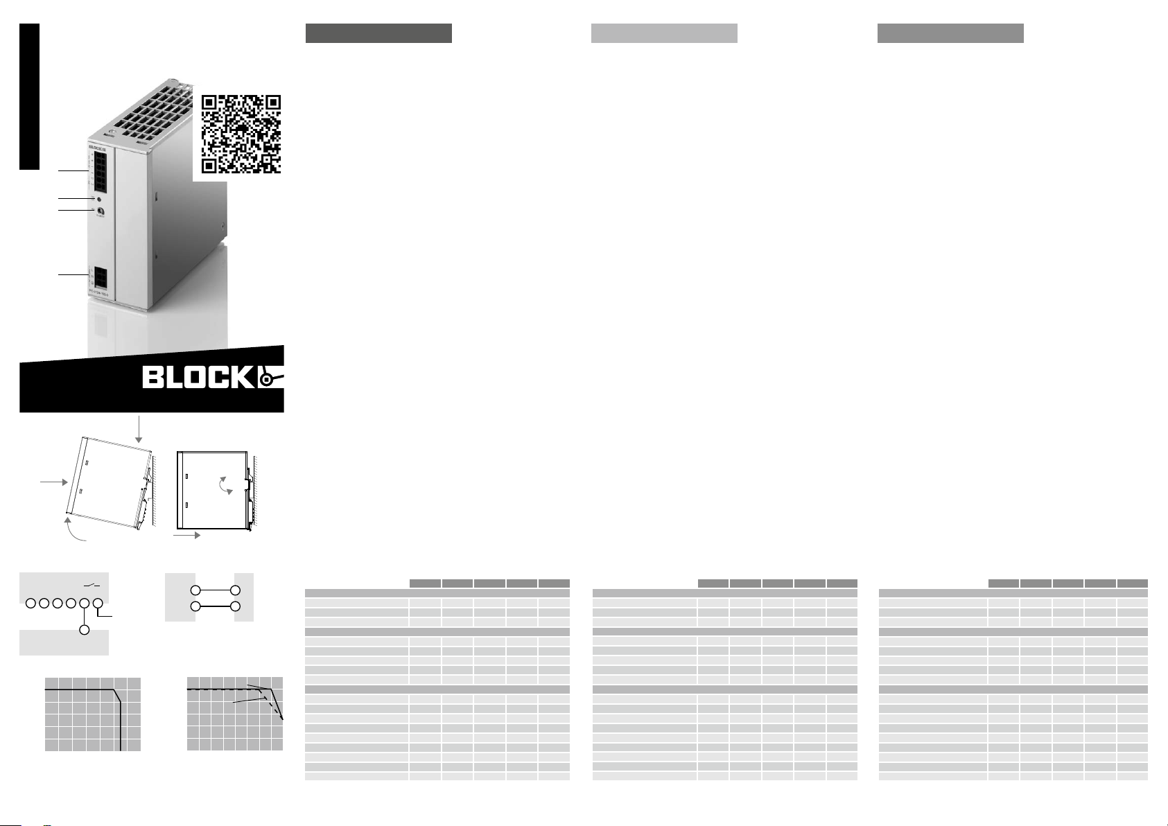
Fig. 1
français / english / deutsch
1
2
3
4
BLOCK Transformatoren-Elektronik GmbH
Max-Planck-Straße 36-46 . 27283 Verden, Germany
[email protected] . block.eu
#005-0178 21.10.2016
block.eu
Fig. 2
III
deutsch english français
Installation Installation Installation
Das Betriebsmittel immer im spannungsfreien Zustand
montieren und verdrahten. Die Installation ist entsprechend
den örtlichen Gegebenheiten, einschlägigen Vorschriften, nationalen Unfallverhütungsvorschriften und den
anerkannten Regeln der Technik durchzuführen. Dieses
el e k t r isch e Be t r iebs m it t el ist ei n e Komp o nente, di e zu m
Einbau in elektrische Anlagen oder Maschinen bestimmt ist
und erfüllt die Anforderungen der Niederspannungsrichtlinie (2014/35/EU). Der geforderte Mindestabstand zu
benachbarten Teilen ist einzuhalten, um die Kühlung nicht zu
behindern!
block.eu
Anschluss
Fig. 1
DC Au sgän ge (++--) un d potent i a l freier „D C OK“ Kon t a k t
1
LE D St a t usan z e ige „D C OK “
2
Einstellung der Ausgangsspannung
3
AC Netzeingang (L N PE)
4
Montage
Fig. 2
AUF TRAGSCHIENE AUFRASTEN
I) Gerätevorderseite leicht nach oben drehen
II) Auf Hutschiene aufsetzen
III) Bis zum Anschlag nach unten schieben
IV) Unten gegen die Befestigungsebene drücken (klick)
V) Leicht am Gerät rütteln, um Verriegelung zu prüfen
Al w a ys dis c o nnec t the eq uipm e nt from the mains su pply , before commencing installation or wiring. Installation must be
carried out according to the prevailing local conditions and
safety regulations, national accident prevention regulations
an d the gene r ally ac c e pted rul e s of te chno l ogy. Th is equi p ment is a component designed for installation into electrical
systems and machines, and fulfils the requirements of the
low voltage guidelines (2014/35/EU). The required minimum
spacing to neighbouring components must be observed to
gu aran t e e th e requi r e d cooli n g!
Connection
Fig. 1
DC Outputs (++--) and potential-free “DC OK” Signal contact
1
LE D Signa l ling “D C OK”
2
Se t t i n g of outpu t vo ltage
3
AC Line input (L N PE)
4
Mounting
Fig. 2
SNAP ON SU P PORT RAIL
I) Tilt the unit slightly rearwards
II) Fit the unit over top hat rail
III) Slide it downward until it hits the stop
IV) Press against the bottom front side for locking (click)
V) Shake the unit slightly to check the locking action
Eviter tout contact avec des éléments conducteurs/sous
tension. Ne jamais monter ou câbler le matériel lorsqu‘il est
sous-tension. L‘installation doit être réalisée conformément
aux recommandations locales, aux normes de sécurité
en vigeur , aux directives nationales de prévention des
accidents ainsi qu‘ aux normes techniques reconnues. Cet
équipement est un composant destiné à un montage sur des
installations électriques ou sur des machines, il remplit les
exigences de la directive basse tension (2014/35/EU). Pour
ga r antir une conv e c t i on suf fis a nte, resp e c t e r le dég a gement minimale!
Connexion
Fig. 1
1
2
3
4
Montage
Fig. 2
MO N TA GE: EN C LIQUETER SU R LE PROF I LÉ
I) Pousser le module légèrement en arrière
II ) Le plac e r sur le pr o f i lé
II I ) Pous s e r vers le ba s jusq u ‘à la bu t ée
IV) Pousser vers l‘avant pour encliqueter (click)
V) Secouer légèrement pour vérifer l‘encliquetage
So r t i e CC (++--) et sa ns pot en t i el “DC OK ” Si gnal so r t ie
LED Indicateur “DC OK”
Ré g lage de la tensi o n de sor tie
En t r é e CA (L N PE)
II
I
IV
Fig. 3 Fig. 4
+ – 13 14–
/%
out
DC OK
+
+
max. 30 Vac / Vdc 1 A
–
LINE
+
Leitung 1 + 2 = Leitungslänge
Conducter 1 + 2 = Cable length
Câble 1 + 2 = Longueur de câble
/%
I
N
100
80
60
40
20
0
-25 0 25 50 70
Temp. (°C)
Derating
OUTPUT
+
PLC
DIGITAL INPUT
U
/%
out
100
80
60
40
20
0
0 20 40 60 80 100 120
I
Ausgangskennlinie
Output characteristic
Puissance caractéristique
V
1
2
LOAD
Derating @196 ... 264 Vac
Derating @85 ... 195 Vac
Auslösen von StandardLeitungsschutzschaltern
Die aufgeführten Leitungslängen sind experimentell bei ca.
25° C ermittelt worden. Sie dienen als Richtwert für die
Auslegung der DC-seitigen Absicherung durch Leitungsschut zschalter und sollten in der jeweiligen Applikation
kundenseitig überprüft werden. (Fig. 4)
Kabelquerschnitt (mm²) 0,75 1,5 2,5 4 6
PC-0124-050-0
Leitungslänge mit LS B2 20 m 40 m 40 m
Leitungslänge mit LS B3 20 m 40 m 40 m
Leitungslänge mit LS B4 20 m 40 m
PC-0124-100-0
Leitungslänge mit LS B2 20 m 40 m 40 m
Leitungslänge mit LS B3 20 m 40 m 40 m
Leitungslänge mit LS B4 20 m 20 m 40 m
Leitungslänge mit LS B6 20 m
Leitungslänge mit LS C2 20 m 20 m
PC-0124-200-0
Leitungslänge mit LS B2 40 m 40 m 40 m 40 m 40 m
Leitungslänge mit LS B3 20 m 40 m 40 m 40 m 40 m
Leitungslänge mit LS B4 20 m 40 m 40 m 40 m 40 m
Leitungslänge mit LS B6 20 m 20 m 40 m
Leitungslänge mit LS C2 20 m 40 m 40 m 40 m
Leitungslänge mit LS C4 20 m 20 m 40 m
Leitungslänge mit LS C6 20 m 20 m
Leitungslänge mit LS K2 40 m 40 m
Leitungslänge mit LS K4 20 m
Fast tripping of standard
bi-metal circuit breakers
The specified cable lengths are theoretical values only and
were determined in respect to approx . 25° C. They serve
only as a guide for determining the protection through a
st a n dard ci r c uit br e a ker an d must be ve r i fied in th e re spec tiv e appli c a t ion. (F i g . 4)
Cable cross-section (mm²) 0,75 1,5 2,5 4 6
PC-0124-050-0
Cable length with CB B2 20 m 40 m 40 m
Cable length with CB B3 20 m 40 m 40 m
Cable length with CB B4 20 m 40 m
PC-0124-100-0
Cable length with CB B2 20 m 40 m 40 m
Cable length with CB B3 20 m 40 m 40 m
Cable length with CB B4 20 m 20 m 40 m
Cable length with CB B6 20 m
Cable length with CB C2 20 m 20 m
PC-0124-200-0
Cable length with CB B2 40 m 40 m 40 m 40 m 40 m
Cable length with CB B3 20 m 40 m 40 m 40 m 40 m
Cable length with CB B4 20 m 40 m 40 m 40 m 40 m
Cable length with CB B6 20 m 20 m 40 m
Cable length with CB C2 20 m 40 m 40 m 40 m
Cable length with CB C4 20 m 20 m 40 m
Cable length with CB C6 20 m 20 m
Cable length with CB K2 40 m 40 m
Cable length with CB K4 20 m 20 m
Déclenchement des
disjoncteurs standards
Les longueurs de câble sont déterminées expérimentaleme n t à envir o n 25 ° C. Ils se r vent de re p ères pou r la conception de la protection côté DC par disjoncteur et doivent
être vérifiés par le client dans l‘application respectif (Fig. 4)
Section du câble (mm²) 0,75 1,5 2,5 4 6
PC-0124-050-0
Longueur de câble avec DJ B2 20 m 40 m 40 m
Longueur de câble avec DJ B3 20 m 40 m 40 m
Longueur de câble avec DJ B4 20 m 40 m
PC-0124-100-0
Longueur de câble avec DJ B2 20 m 40 m 40 m
Longueur de câble avec DJ B3 20 m 40 m 40 m
Longueur de câble avec DJ B4 20 m 20 m 40 m
Longueur de câble avec DJ B6 20 m
Longueur de câble avec DJ C2 20 m 20 m
PC-0124-200-0
Longueur de câble avec DJ B2 40 m 40 m 40 m 40 m 40 m
Longueur de câble avec DJ B3 20 m 40 m 40 m 40 m 40 m
Longueur de câble avec DJ B4 20 m 40 m 40 m 40 m 40 m
Longueur de câble avec DJ B6 20 m 20 m 40 m
Longueur de câble avec DJ C2 20 m 40 m 40 m 40 m
Longueur de câble avec DJ C4 20 m 20 m 40 m
Longueur de câble avec DJ C6 20 m 20 m
Longueur de câble avec DJ K2 40 m 40 m
Longueur de câble avec DJ K4 20 m
Page 2
deutsch english français
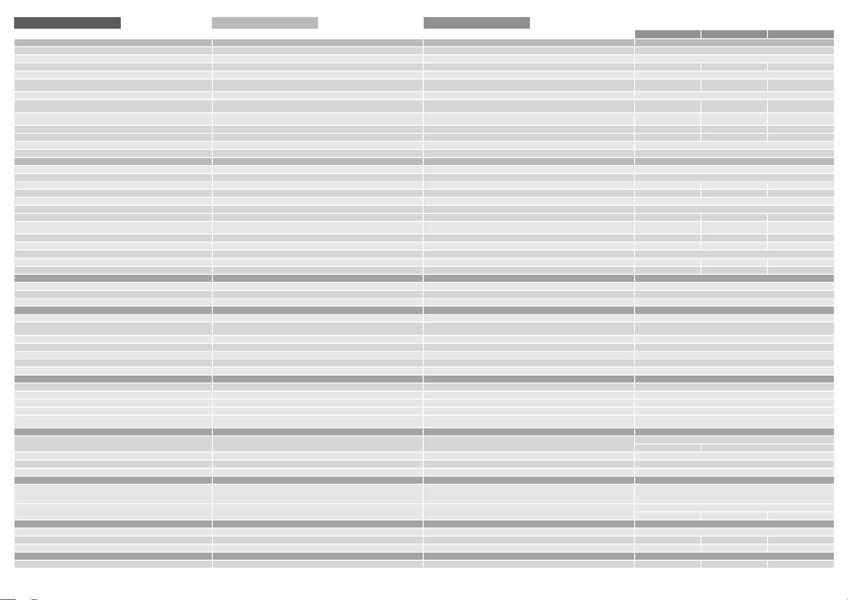
Technische Daten Technical data Données techniques
Eingangsdaten Input data
Eingangsnennspannung Nominal input voltage
Eingangsspannungsbereich Input voltage range
Eingangsspannungsderating Input voltage derating
Nennfrequenzbereich Frequency range Gamme de fréquences 47 Hz - 63 Hz / 0 Hz
Eingangsnennstrom (Nennlast) Nominal input current (nominal load)
Einschaltstrombegrenzung Inrush current limitation
Einschaltzeit nach Anlegen der Netzspannung Turn-on time after applying the main voltage
Netzausfallüberbrückungszeit (Nennlast) Mains buffering (full load)
Eingangssicherungen intern Internal fuses
Empfohlener Leitungsschutzschalter (Charakteristik) Recommended power circuit breaker (characteristic)
Transienten Überspannungsschutz Varistor Transient surge voltage protection varistor
Anschlüsse Eingang Terminals input
Ausgangsdaten Output data
Ausgangsnennspannung Nominal output voltage
Ausgangsspannungsbereich Output voltage range
Ausgangsstrom Nominal output current
Ausgangsstrombegrenzung Konstantstrom Output current limitation constant current
Parallelschaltbar Parallel operation
Serienschaltbar Serial operation
Verlustleistung Leerlauf / Nennlast Power losses (Stand-by / nominal load)
Max. Verlustleistung Maximum power losses Dissip. puissance max.
Wirkungsgrad Efficiency
Restwelligkeit (Nennlast) Ripple/noise
Rückspeisefestigkeit Resistance to reverse feed max. (nominal load)
Schutz gegen interne Überspannung (OVP) Protection against internal surge voltage (OVP)
Anschlüsse Ausgang Terminals output
Signalisierung Signaling
Statusanzeige „DC OK“ LED grün leuchtet dauerhaft Signaling “DC OK“ LED green lit permanently Indicateur “DC OK“ LED vert allumée en permanence Uout > 21,5 V
Signalausgang „DC OK“ Relais, Kontakt geschlossen: Signal contact “DC OK“ Relay, contact closed
Anschlüsse Signalisierung Terminals signaling
Umwelt Environment
Lagertemperatur Storage temperature
Umgebungstemperatur Operational temperature
Derating Derating Derating -5 %/K > +60° C (196 ... 264 Vac) -2,5 %/K > +50° C (85 ... 195 Vac)
Konvektionskühlung Convection cooling Refroidissement par convection
Luftfeuchtigkeit keine Betauung Humidity no condensation Humidité sans condensation 5 ... 96 %
Erforderlicher Mindestabstand (seitlich) Required minimum spacing (left / right) Distance minimale requise (latéral) --Erforderlicher Mindestabstand (oben / unten) Required minimum spacing (over / under) Distance minimale requise (haut / bas) 50 mm
Allgemeine Daten General data Autres caractéristiques
Schutzart nach IEC 60529 Degree of protection acc. to IEC 60529 Degrée de protection selon IEC 60529 IP 20
Schutzklasse nach EN 61140 Protection class acc. to EN 61140 Classe de protection selon EN 61140 I
Überspannungskategorie Overvoltage category Catégorie de surtension III
Einsatz in Bereichen mit Verschmutzungsgrad 2 For installation in Pollution Degree 2 environment Pour installtion dans un environment de pollution 2
Zum Anschluss Kupferkabel mit min. 75° C verwenden Use Copper Conductors only, rated 75° C
Normen Safety standards Normes
Sicherheit Safety Sécurité
EMV EMC EMC EN 61204-3
Schutzkleinspannung (SELV/PELV) Safety extra-low voltage (SELV/PELV) Faible tension de protection (SELV/PELV) IEC 60364-4-41 (DIN VDE 0100-410)
CE gemäß 2014/30/EG und 2014/35/EU CE acc. to 2014/30/EU and 2014/35/EU Conforme à la directive 2014/30/EU et à la directive basse tension 2014/35/EU
Prüfzeichen Markings Approbation
UL UL UL
GL GL GL
Mechanische Daten Mechanical data Caractéristiques mécaniques
Befestigung auf Normprofilschiene DIN TH35 Mounting on standard rail DIN TH35 Encliquette sur les profilés 35 mm
Gewicht Weight Poids 0,59 kg 0,93 kg 1,6 kg
Maße (B x H x T) Tiefe inklusive TH 35-7,5-DIN-Schiene Dimensions (W x H x D) Depth incl. DIN 35-7.5 rail Dimensions (L x H x P) profondeur avec TH35-7,5 42 x 127 x 126 mm 55 x 127 x 161 mm 95 x 127 x 159 mm
Bestellnummern Order Numbers Numéros de produit
Bestellnummer Order Number
* Für DC Eingangsspannung ist eine geeignete DC- Sicherung erforderlich.
** EMC1 nur in Verbindung mit dem Filter HFE 156-230/10.
* For DC input voltage suitable DC fuse required.
** EMC1 only in conjunction with the filter HFE 156-230/10.
Entrée
Tension nominale d‘entrée
Plage de tension d‘entrée
La tension d’entrée derating
Courant d’entrée nominale (charge nominale)
Limitation courant démarrage
Durée démarrage après connexion de la tension réseau
Protection contre microcoupures pour charge nom.
Fusible internes
Fusible en amont homologué Disjoncteur de circuit (caractéristique)
Protection contre les transitoires varistance
Bornes d‘entrée
Sortie
Tension nominale de sortie
Plage de la tension de sortie
Courant nominal de sortie
Limitation de courant de sortie de courant constant
Parallèlement opérationnelle
Serial opérationnelle
Puissance dissipée (vide/charge nom.)
Rendement
Ondul. résid. (charge nom.)
Protection contre courants d‘amont
Protection contre surtensions internes
Bornes de sortie
Signalisation
Sortie signal
“DC OK“
Bornes de signal
Environnement
Température ambiante stockage
Température ambiante service
Utiliser uniquement des câbles de connexion en cuivre
supportant des plages de températures 75° C
Numéro de produit
* Fusible CC nécessaire.
** EMC1 uniquement en combinaison avec le filtre HFE 156-230/10.
Relais, contact fermé
PC-0124-050-0 PC-0124-100-0 PC-0124-200-0
100 - 240 Vac
-2,5 %/Vac < 97 Vac -2,5 %/Vac < 100 Vac -2,5 %/Vac < 100 Vac
2,3 A (100 Vac) /
1,24 A (230 Vac)
0,25 s (100 Vac) /
0,2 s (230 Vac)
10 / 80 ms
(100 / 230 Vac)
4 AT 6,3 AT 10 AT
6 A, 10 A, 16 A (B,C) 10 A, 16 A (B,C) 10 A, 16 A (B,C)
5 A 10 A 20 A
typ. 5,5 A typ. 11-13 A typ. 22 A
1,2 W / 14,6 W (230 Vac) 6,6 W / 24,4 W (230 Vac) 7,2 W / 42,4 W (230 Vac)
19,4 W (100 Vac /
24 V / 5 A)
typ. 89 % typ. 91 % typ. 92 %
typ. 30 mVss typ. 50 mVss typ. 70 mVss
max. 41 Vdc max. 40 Vdc max. 40 Vdc
Push-In, max 2,5 mm² Push-In, max 2,5 mm² Push-In, max 6 mm²
EN 60335-1
UL/CSA 60950 recognised (E213214), UL 508 listed (E219022)
UL-Notes: Overcurrent protection is to be supplied max. 16 A.
Output disconnecting means shall be provided during installation.
GL (Germanischer Lloyd) classified, Environmental category: C.
EMC2, EMC1 ** EMC2 EMC2
PC-0124-050-0 PC-0124-100-0 PC-0124-200-0
85 - 264 Vac (120 - 372 Vdc *)
2,74 A (100 Vac) /
1,25 A (230 Vac)
< 30 A, NTC
1,3 (100Vac) /
0,25 s (230Vac)
15 / 17 ms
(100 / 230 Vac)
o
Push-In, max 2,5 mm²
24 Vdc ± 1%
23 ... 28,5 Vdc
o
o
31,3 W (100 Vac /
24 V / 10 A)
max. 35 Vdc
Uout > 21,5 V max. 30 V / 1 A
Push-In, max 2,5 mm²
-25° C ... +70° C Anlauf bei -40° C typgeprüft
-25° C ... +70° C Device start at - 40° C type-tested
-25° C ... +85° C
o
o
o
EN 61558-2-16, EN 60950-1
o
o
5,56 A (100 Vac) /
2,23 A (230 Vac)
0,45 s (100Vac) /
0,2 s (230Vac)
(100 / 230 Vac)
68,3 W (100 Vac /
8 / 20 ms
24 V / 20 A)
 Loading...