

Page 1
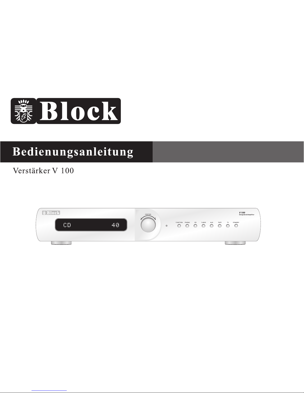
Hi-Fi Stereo Amplifier V 100
Instruction Manual
1--11
12--21
Page 2
Page 3
Page 4
Page 5
Page 6
A A
A A
Page 7
Bedienung am Gerät
Power
Um das Gerät in den Betrieb zu nehmen,
muss auf der Rückseite des Gerätes der
Power Schalter auf „on“ stehen
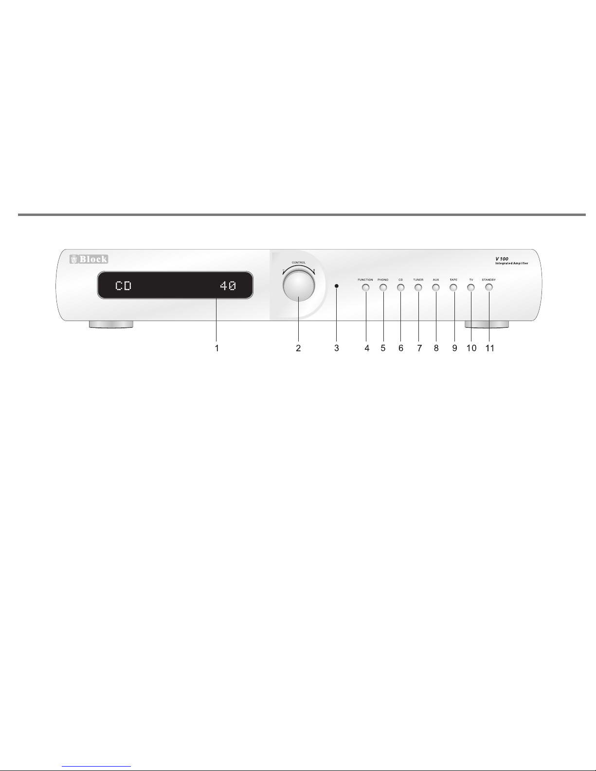
1. VFD Display: Im Display bekommen Sie die
Information, welche Quelle Sie gerade hören
2. Lautstärke Regler: Mit dem Lautstärke Regler
stellen Sie die Lautstärke, Bass, Hochton usw. ein.
3. LED Anzeige: Die LED leuchtet rot, wenn das
Gerät in Bereitschaft ist.
4. Funktion Taste: Mit dieser Taste gehen Sie im
Menu auf Bass, Hochton, Balance Reset.
5. Plattenspieler Eingangs Wahltaste
6. CD Eingangs Wahltaste
7. Radio Eingangs Wahltaste
8. Aux Eingangs Wahltaste
9. Tape Eingangs Wahltaste
10. TV Eingangs Wahltaste
11. Standby: Taste, um das Gerät an und aus zu schalten.
S-6-
Page 8
-+-
+
Page 9
-+-
+
CONTROL
P
t
r
c
e
e
s
l
s
e
t
s
o
R 100
AM/FM RDS PLL Tuner
Page 10
Page 11
Page 12
K
4
Page 13

INTRODUCTION & CONTENTS
Contents
Introduction & Contents
Safety instructions
Remote control
Front panel controls
Rear panel connections
Making the connections
Installation and position
Tro ubl e sho oti ng
Specifications
12
13,14
15
16
17
18
19
21
20
Congratulations on purchasing this V 100 a mpl ifi er. I t ha s be en
developed fo llo win g an extensive re sea rch a nd development pro gra m
that has culminated in wha t w e rega rd as an exc eptional mid -ra nge
hi-fi product.
We tru st th at th is am pli fie r wil l giv e you h our s of li stening pleasure,
and provide years of unparalleled performance.
Please do not operate this product at high volume level s imm edi ate ly
after switching on.
Introduction
P12
Page 14
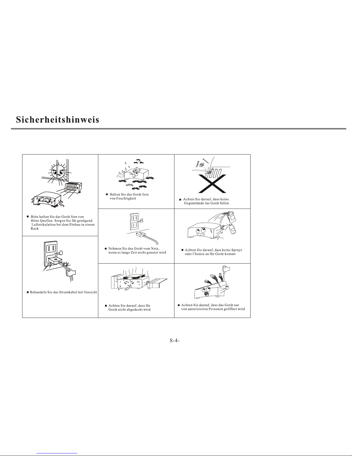
SAFETY INSTRUCTIONS
Safety Instructions
CAUTION: To reduce the ris k of e lec tri c sh ock , do n ot remove an y
cover.
N O U S E R- S E R V I CE A B L E PA R T S IN S ID E , RE F E R AN Y
SERV ICI NG TO QUALIFIED SERVIC E PER SON NEL .
IMPORTANT SAFETY IN STR UCT ION S
* Read and keep these instructions available for futu re re fer enc e.
* For indoor use only.
* The un it mu st only be co nne cte d to a su ita ble m ains power sup ply
using the mains power lead provided.
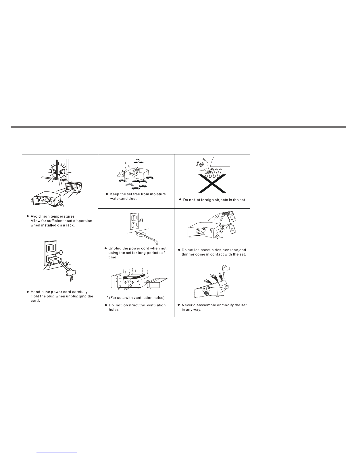
* To re duc e the r isk of fire or e lec tri cal shock, d o not e xpo se this
unit to rain or moisture.
* The ap par atu s sha ll no t be ex pos ed to d rip pin g or sp las hin g.
* No obj ect s filled w ith li qui ds, su ch as v ase s, sha ll b e p lac ed on
the apparatus.
* Un plu g the unit from the wal l soc ket duri ng lightning s tor ms an d
when it is not going to be used for a long period of time.
* Take car e that foreign obje cts do not en ter, or liquids are not
spilled, int o the enc los ure thr oug h any ope nin gs. If th is should
happen, r efe r to quali fie d servi ce p ers onn el befo re atte mpt ing to
use.
* Ensure ad equ ate ve nti lat ion - do not cov er thi s u nit with curtains,
etc.
* Do n ot i nst all near a ny h eat sourc e, s uch as rad iat ors , or ot her
equipment that produces heat.
* Protect the mains power cable from being damaged.
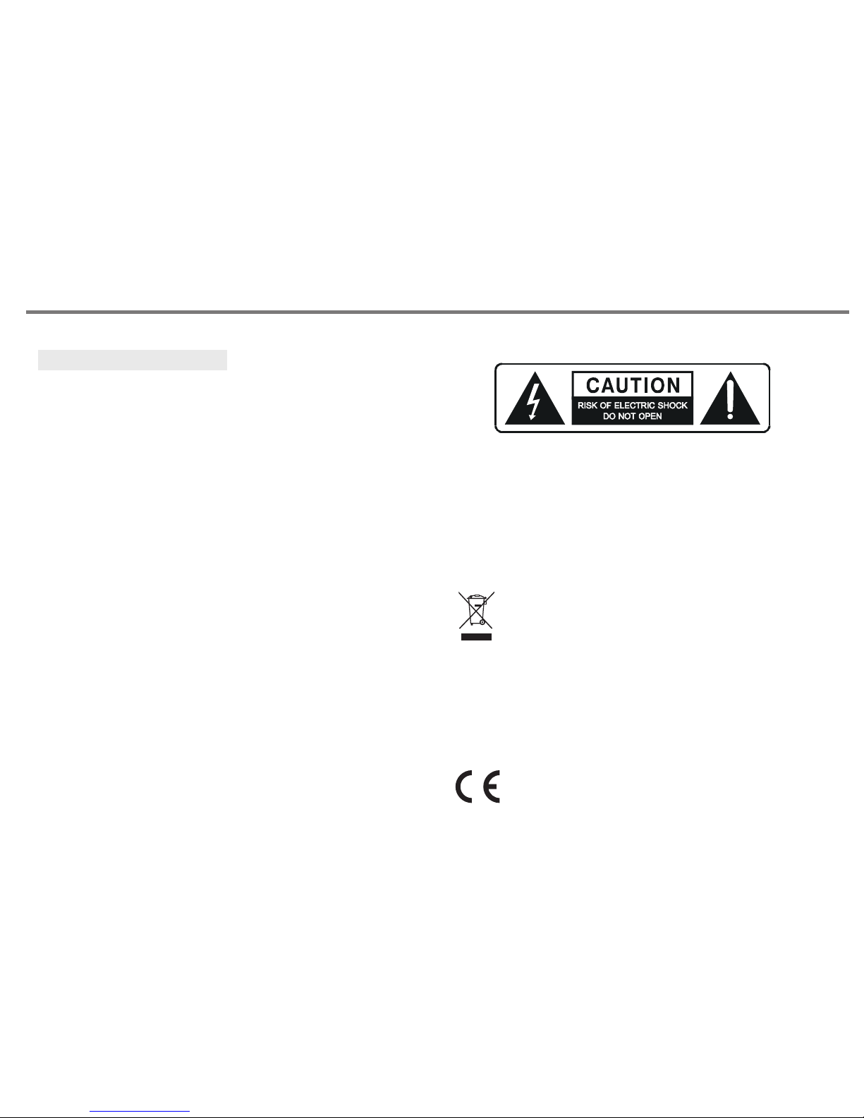
The lig htn ing flash s ymb ol wit h the ar row hea d within an eq uil ate ral
triangle is in ten ded to al ert the user to the pr ese nce of uninsulated
'dangerous volt age ' wit hin t he pr odu ct' s enclosure tha t may b e
suff ici ent t o con sti tut e a ris k of el ectric shock to persons.
The exc lam ati on point wi thi n an equ ila ter al tr ian gle is i nte nde d to
alert t he us er to im por tan t ope rat ing a nd mai nte nan ce ins tructions
in the service literature relevant to th is ap pli anc e.
"Information for the consumer"
Disposal of your old product
Your p ro du ct i s de si gn ed a nd m an uf ac tu re d wi th h ig h qu al it y ma te ri al s an d co mp on en ts ,
which can be recycled and reused.
When this crossed out wheeled bin symbol is attached to a product i t me an s th e pr od uc t is
covered by the European Directive 2002/96/EC.
Please make yourself aware of the local collection system for e le ct ri ca l an d
electronic products.
Please act according to your loca rules and do not dispose of your old products w it h
your normal household waste. Th e co rr ec t di sp os al o f yo ur o ld p ro du ct w il l he lp p re ve nt
potential negative consequences for the environment and human health.
This product complies with European low votage (73/23/EEC)
and electromagnetic compatibility (89/336/EEC) directives .
P13
Page 15
SAFETY INSTRUCTIONS
Notes On Use
P14
Page 16
BATTE RY INS TAL LATION
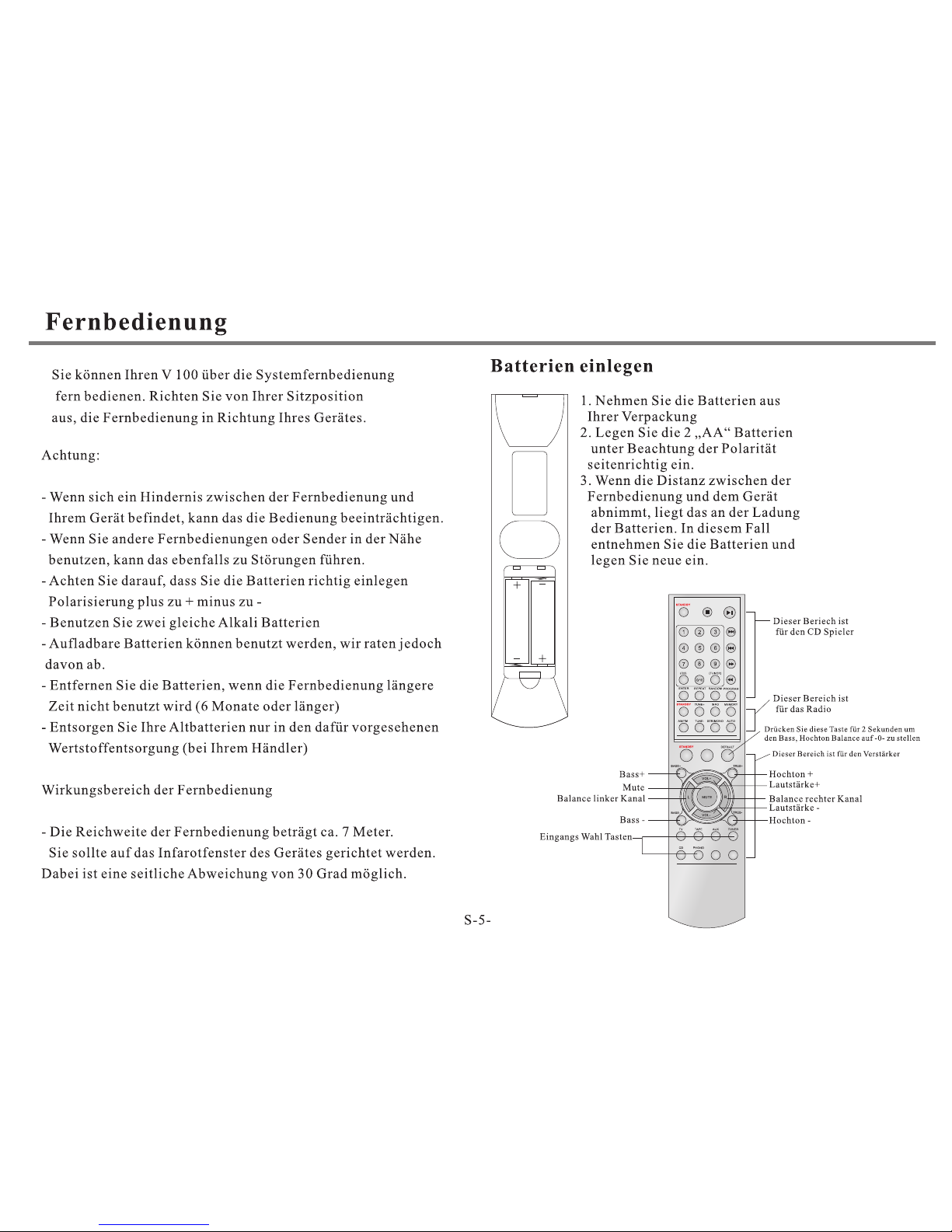
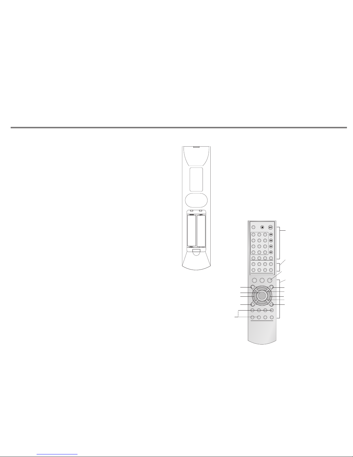
By using the provided remote control unit the V 1 00 ca n be
controlled from your listening position. To use th e rem ote
control unit, point it at the REMO TE SE NSO R win dow o f the
receiver.
Notes:
-Even if the remote control unit is operat ed wi thi n the
effe cti ve ra nge , rem ote c ont rol o per ati on ma y be im pos sible if
there are any obstacles between the unit and th e rem ote
control.
-If the remote control unit is ope rat ed ne ar ot her a ppl ian ce
which generate infrared rays, or if other rem ote c ont rol
devices using infrared rays are used near the unit, it ma y
operate incorrectly.
Precautions concerning batteries
-Be sure to insert the batteries with c orr ect p osi tiv e+ an d
negative - polarities.
-Use batteries of the same type. Neve r use d ifferent types of
batteries together.
- Rechargeable and non-rechargeable batteries can be used.
Refer to the precautions on their labels.
-When the remote control unit is not to b e use d for a l ong
time(more than a month), remove the b att eri es fr om th e
remote control unit to prevent them f rom l eak ing . If th e lea k,
wipe away the liquid inside the battery compartment and
replace the batteries with new ones.
-Do not heat or disassemble batteries and never dispo se of
old batteries by throwing them in a fire.
REMOTE CONTROL OPER ATI ON RA NGE
Use the remote control unit within a range of about 7
meters and the angles of up to 30 degrees aiming at
the remote sensor.
1. Rem ov e the b at tery co mp artme nt cove r.
2. Ins er t two "AA " dry bat te ries.
Make s ur e tha t th e batte ri es are in serte d wi th thei r
posi ti ve "+ " an d negat iv e "-" p ol es posi ti oned co rrect ly.
3. Clo se t he co ve r until i t cl icks.
If the d is tan ce r equir ed b etwee n the rem ot e contr ol u nit a nd
main u ni t dec re ases, t he b atter ies are e xh auste d. In thi s ca se,
repl ac e the b at terie s wi th ne w on e.
REMOTE CONTROL
P15
STANDBY
1
2
3
4
5
6
7
8
9
0/10
ENTER
REPEAT
PROGRAM
STANDBY
(CD) (TUNER)
RANDOM
AM/FM
TUNE+
TUNE-
INFO
STR/MONO AUTO
MEMORY
STANDBY
DEFAULT
MUTE
BASS+
BASS-
TREB+
TREB-
L R
TV TAPE
AUX TUNER
CD PHON O
VOL+
VOL-
Thi s part fo r CD play er C 100
Thi s part fo r
Tun er R 10 0
Thi s part fo r Amp lifie r V 100
Pre ss and ho ld for 2 se conds t o setup
bas s, treb le, bal ance to " middl e" posi tion
Treb le lev el up +
Treb le lev el do wn -
Volu me leve l up +
Volu me leve l down -
Bal ance, m ove to ri ght cha nnelBal ance, m ove to le ft chan nel
Bas s level u p +
Bas s level d own-
Mut e
INP UT SOUR CE SE LECT:
PHO NO
CD
TUN ER
AUX
TAPE
TV
A A
A A
+
-
+
-
Page 17
FRONT PANEL CONTROLS
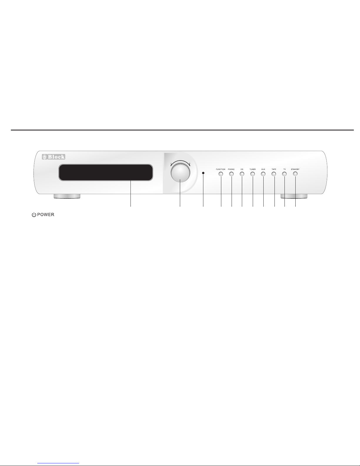
1. VFD DISPLAY. Will gi ve th e ind ica tio n of le vel c ont rol a nd
input source selected.
2. ROTARY CONTROL KN OB. This allows adjustm ent o f
parameters such as volume, bas s, tr ebl e, ba lan ce.
3. LED INDICATOR, i t wil l be tu rn on i n red c olo ur wh en th e uni t
is in standby mode.
4. FUNCTION BUTTO N. All ows a cce ss to m enu features such
as bass, treble, ba lan ce, r ese t.
5. PHONO INPUT SELE CTOR SW ITC H.
6. CD INPUT SELE CTOR SW ITC H.
7. TUN ER IN PUT SEL ECTOR SWITCH.
8. AUX INPUT SELE CTOR SW ITC H.
9. TAP E INP UT SELECTO R SWI TCH .
10. TV I NPU T SE LEC TOR SWITCH.
11. STANDB Y BUTTO N. Pr ess t his b utt on to turn to standby
mode, press again return to n orm al mo de.
P16
CONTRO L
CD 4 0
V 100
Inte grate d Ampli fier
POWER SWITCH ON REA R PANEL,
TURN IT ON BE FOR E USE THE U NIT.
1 2
3
4
5 6
7
8 9 10
11
Page 18
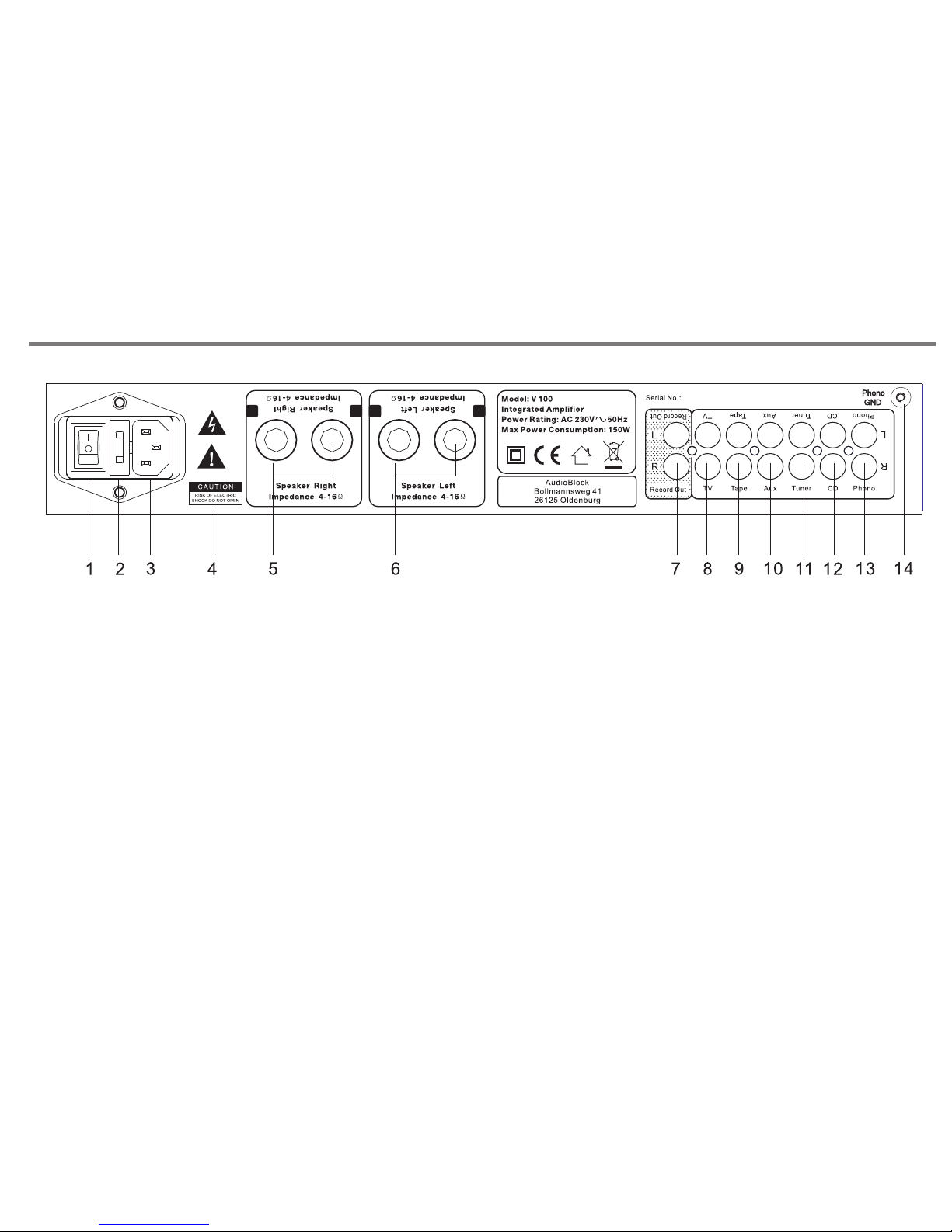
REAR PANEL CONNECTIONS
P17
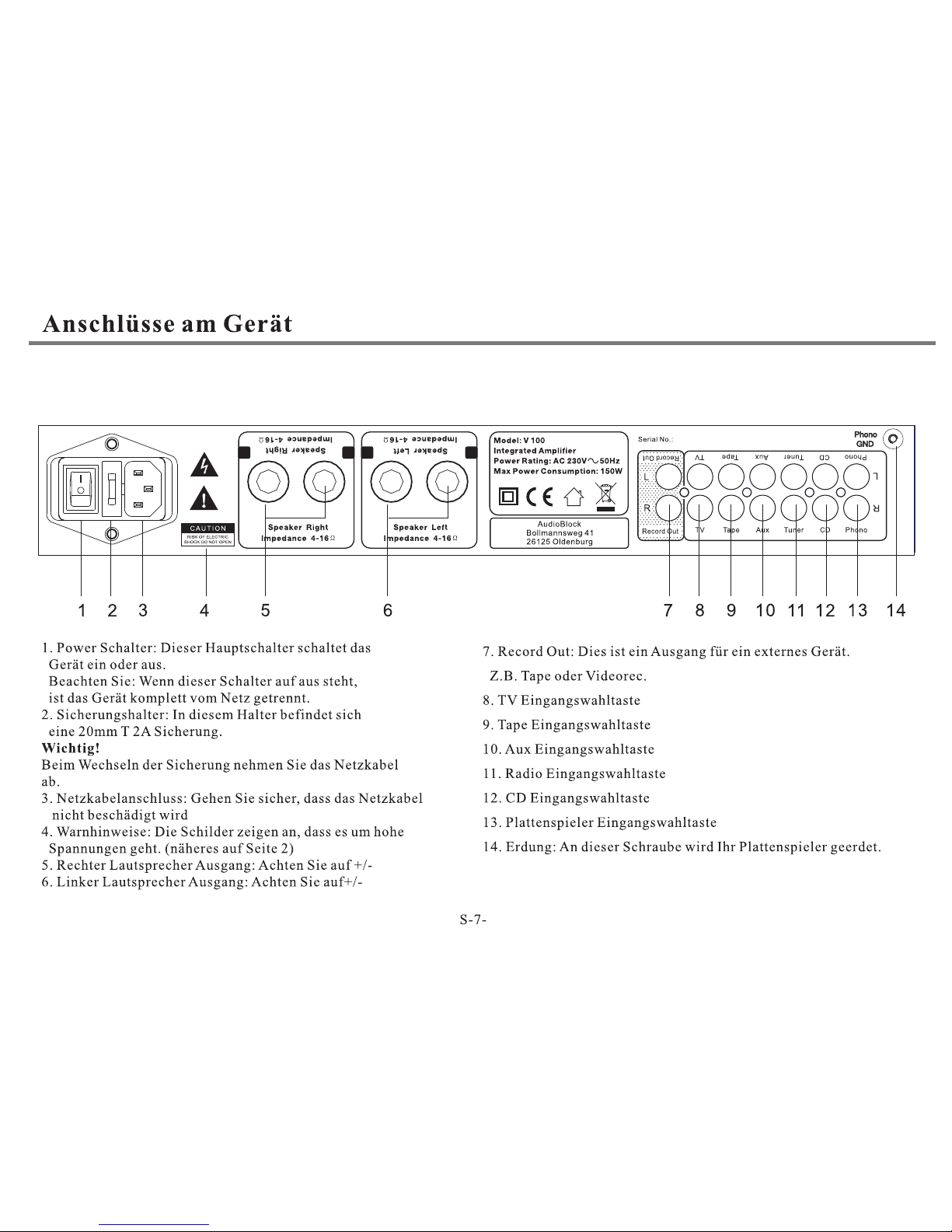
1. POWER SWITCH: Sw itc hes m ain s pow er on /off to internal
components, however please n ote t hat m ain s pow er is s til l
applied to this unit even though this s wit ch ma y be off.
2. FUSE HOLDER: fitted w ith 2 0mm T 2A fus e ins ide .
" IMPORTAN T:"
Remove the mains plug from th e mai ns so cke t bef ore a tte mpt ing
to check/ replace the fu se lo cat ed on t his f use h old er.
3. M AI NS CABL E IN LET JACK: P le ase e ns ure tha t th e inp ut c able st ra in re li ef
bush i s in tac t an d has not b ee n damag ed.
4. WA RNING I CO NS: P le ase be aw ar e tha t th is unit c on tains h igh vol ta ges,
and sh ou ld no t be o pened , pl eas e re fer to pa ge 2 o f this ma nu al.
5/6. LOUD SP EAK ER O UTPUT S. P lease e ns ure t ha t +/- con ne cti on s are mad e
prop er ly be tw een rea r of t he ampl if ier a nd l oudsp ea ker s. E nsure w ir es ar e
not fr ay ed or tou ch ing .
7. L IN E OUTPU T SO CK ETS: This i s fo r con ne ction t o ex terna l ampli fi catio n or
reco rd ing e qu ipeme nt .
8. TV IN PUT SOC KET.
9. TAP E INP UT SOCKET.
10. AUX INPUT SOC KET.
11. TU NER I NPU T SOCKET.
12. CD INPUT SOC KET.
13. PHONO INPUT SOC KET. (F or the connection of a turntable)
14. PH ONO TERMI NA L EA RT H PO ST. It is nec es sar y to p rovid e a ch ass is
eart h co nne ct ion bet we en the tu rn tab le a nd the am pl ifi er. F ailur e to d o
this w il l resul t in a buzz in g or humm in g noi se f rom the l ou dsp ea kers.
-+-
+
Page 19
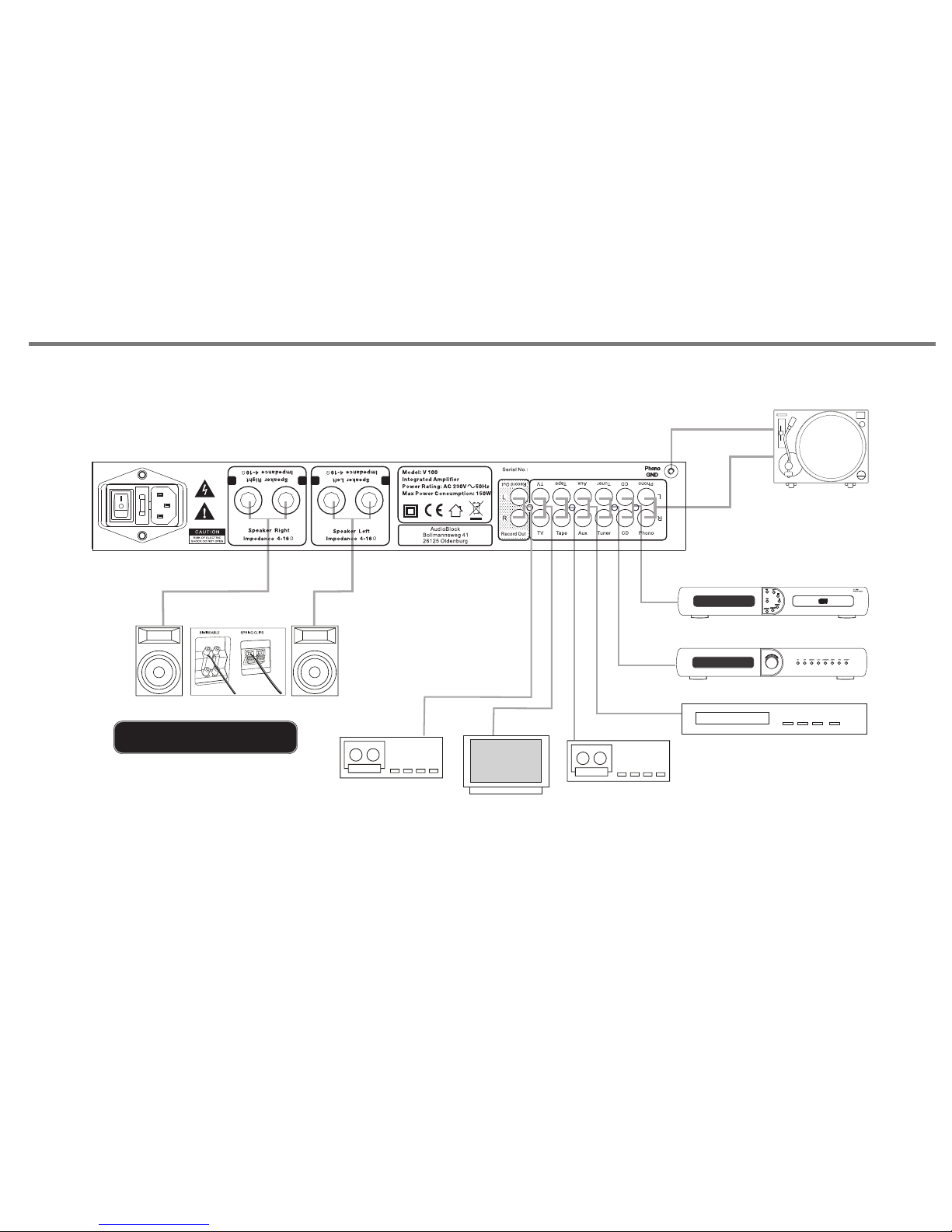
MAKING THE CONNECTIONS
P18
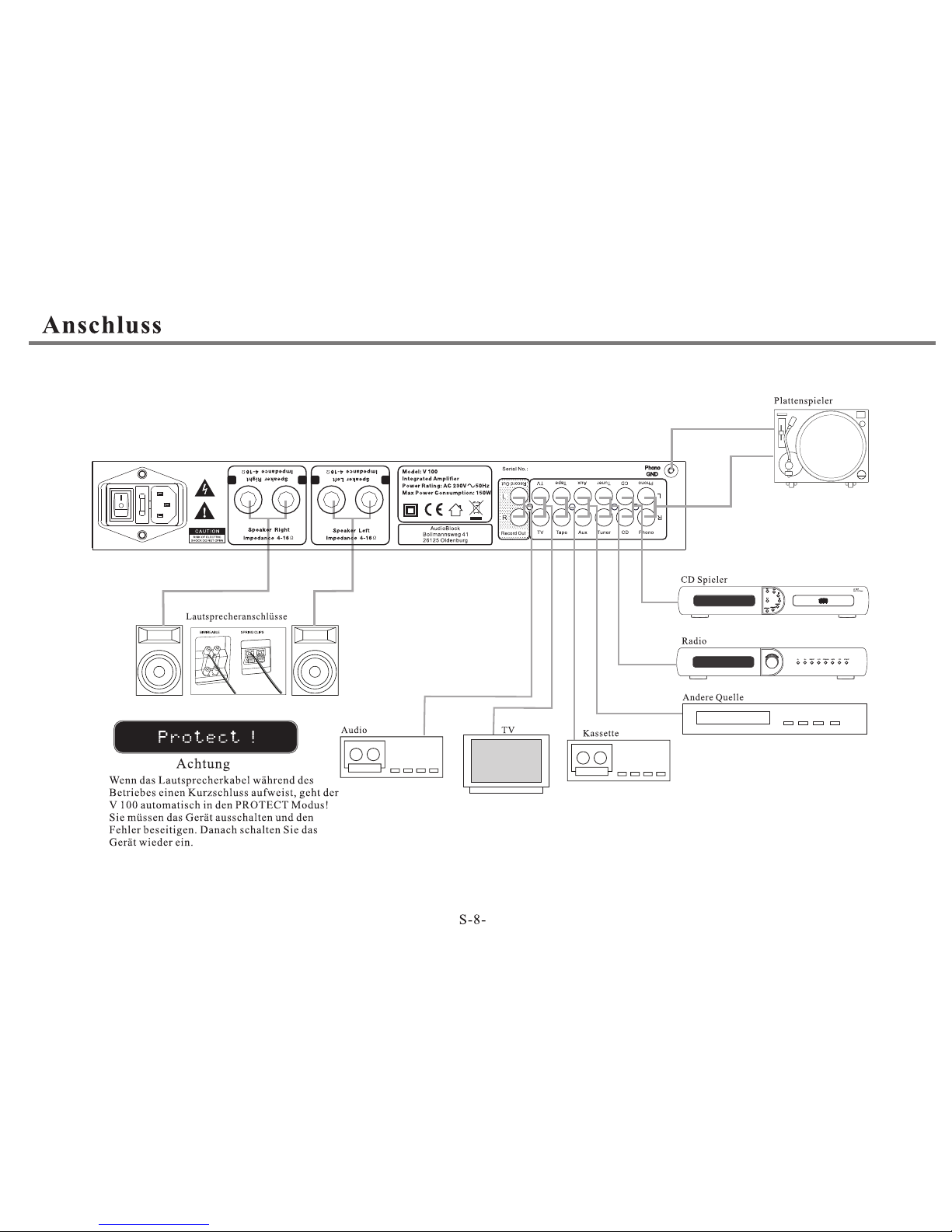
SPE AKER CO NNECT IONS
AUD IO RECO RDER
CAS SETTE D ECK
OTH ER AUDIO S OURCE
TUN ER
CD PL AYER
TUR NTABLE
CONTROL
P
t
r
c
e
e
s
l
s
e
t
s
o
R 100
AM/FM RDS PLL Tuner
TV
Pr o t e c t !
If the spe aker cable is sho rted du rin g wo rki ng, V 100
wil l aut omati cally com e to pro tecti on m ode, and V FD
wil l d ispla y " Prot ect ! ". Now you nee d to tur n off
V 100 , chec k the spe aker ca ble, a nd ma ke sur e all
spe aker ca ble i s conn ected co rrect ly, the n tur n on
V 100 a gain. V 1 00 will r eturn t o norma l worki ng mode .
-+-
+
Page 20
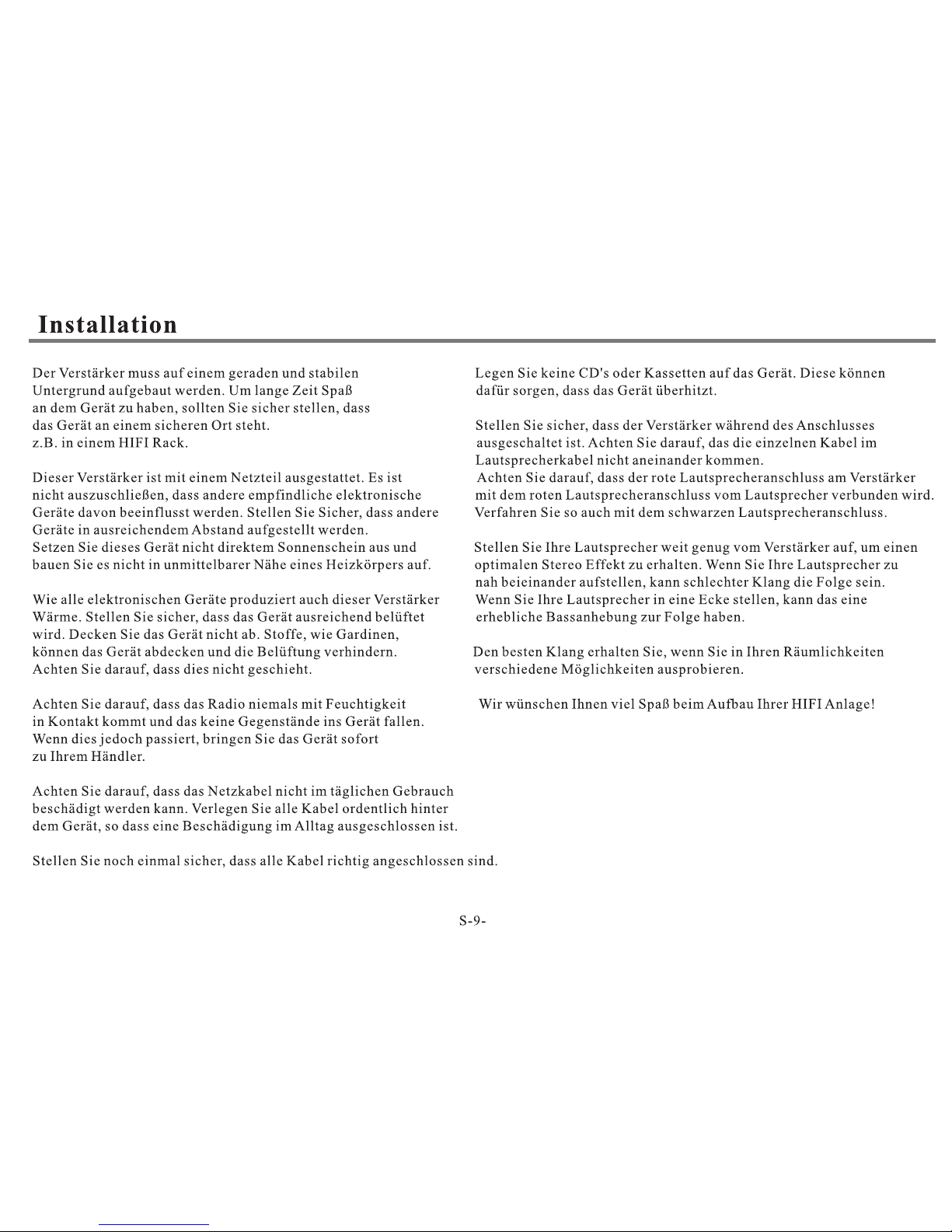
INSTALLATION AND POSITION
V 1 0 0
V 100
P19
Page 21
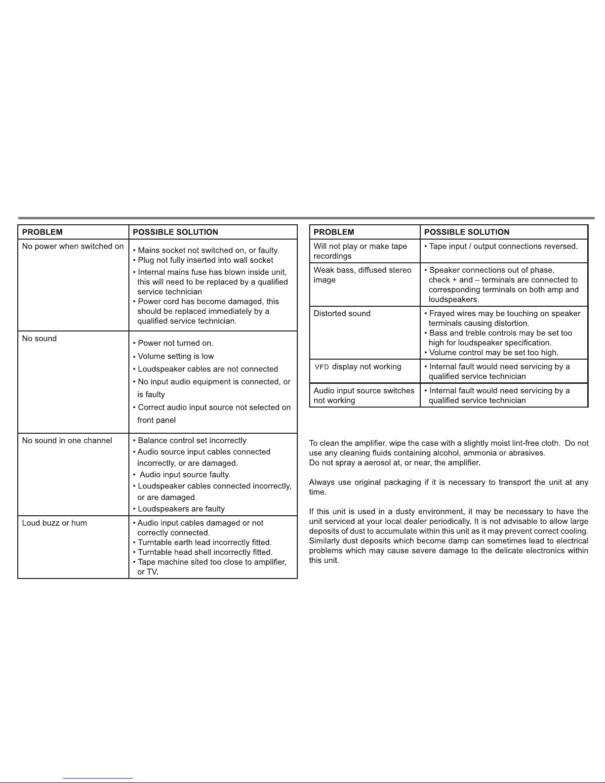
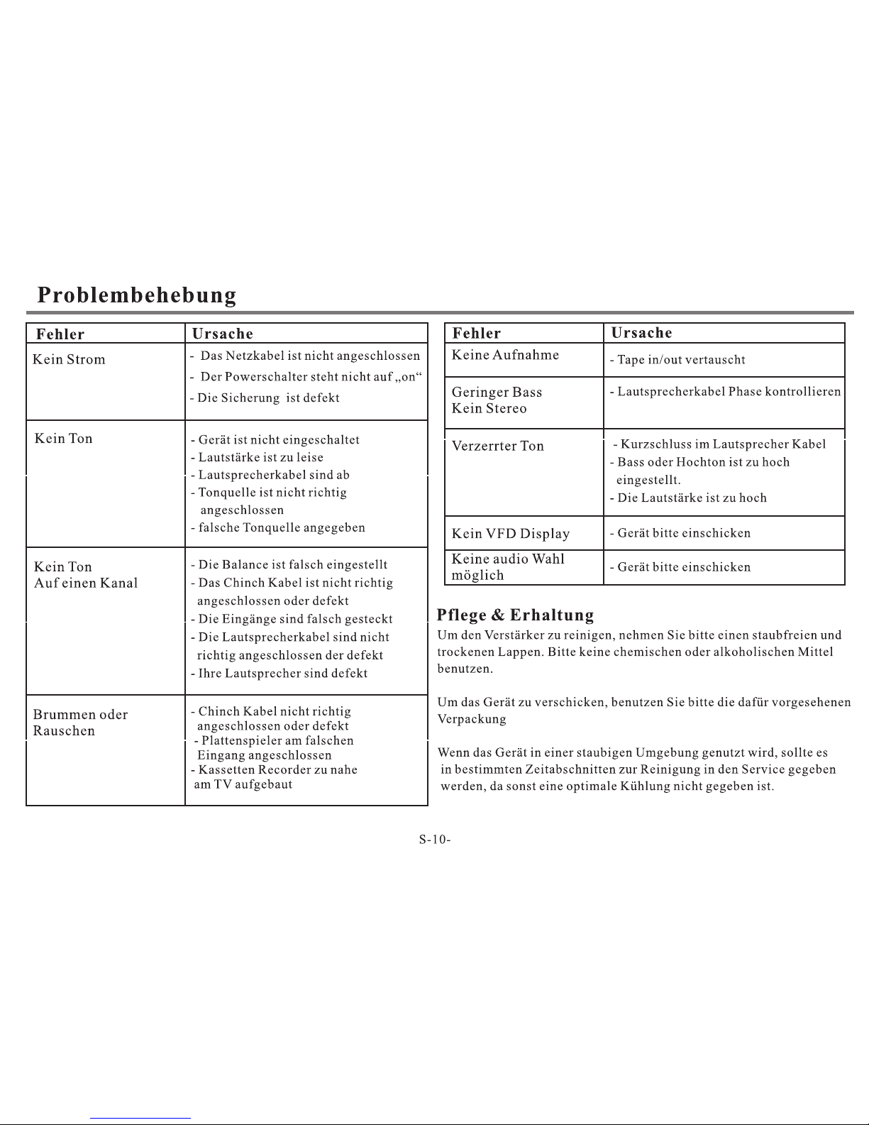
TROUBLE AND SHOOTING
CARE AND MAINTENANCE
P20
Page 22
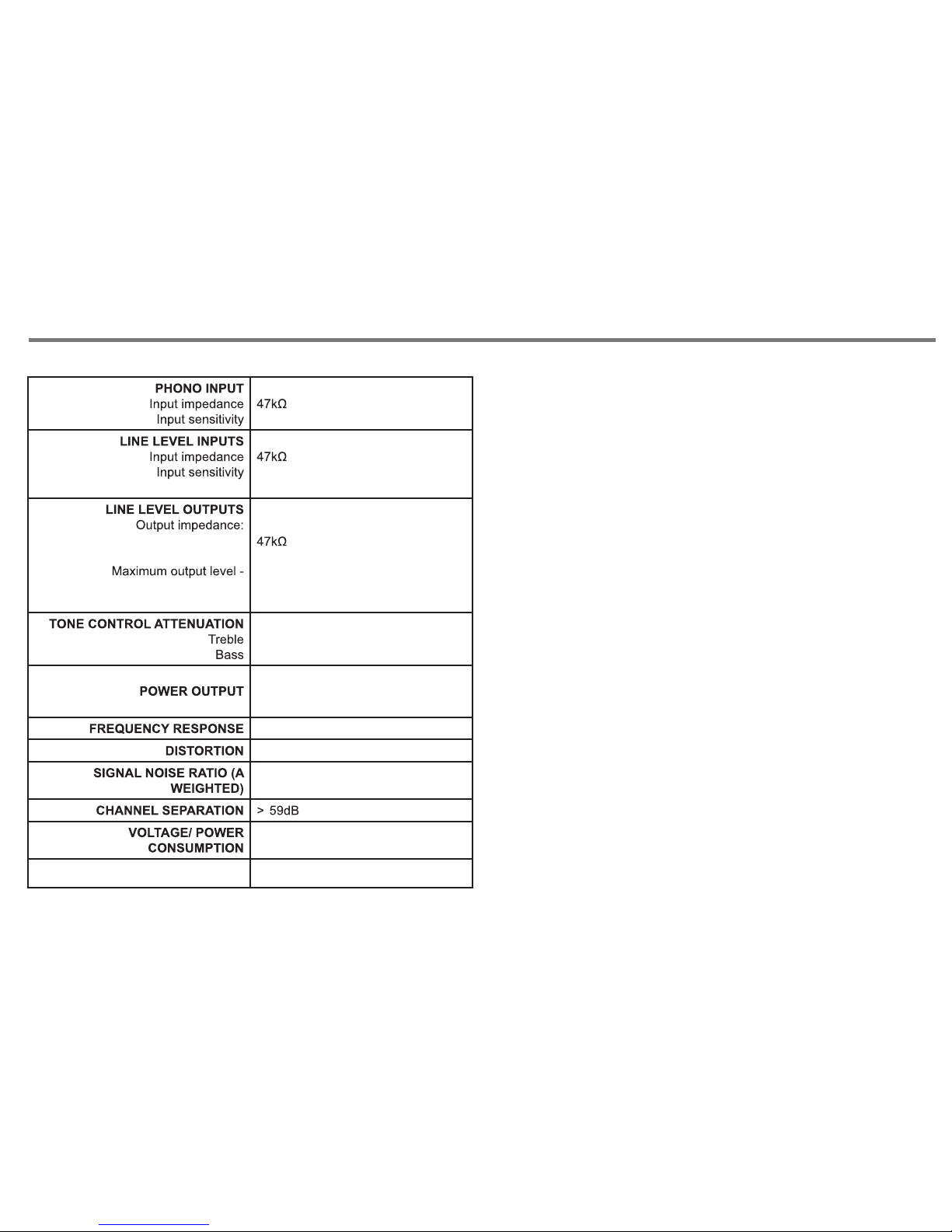
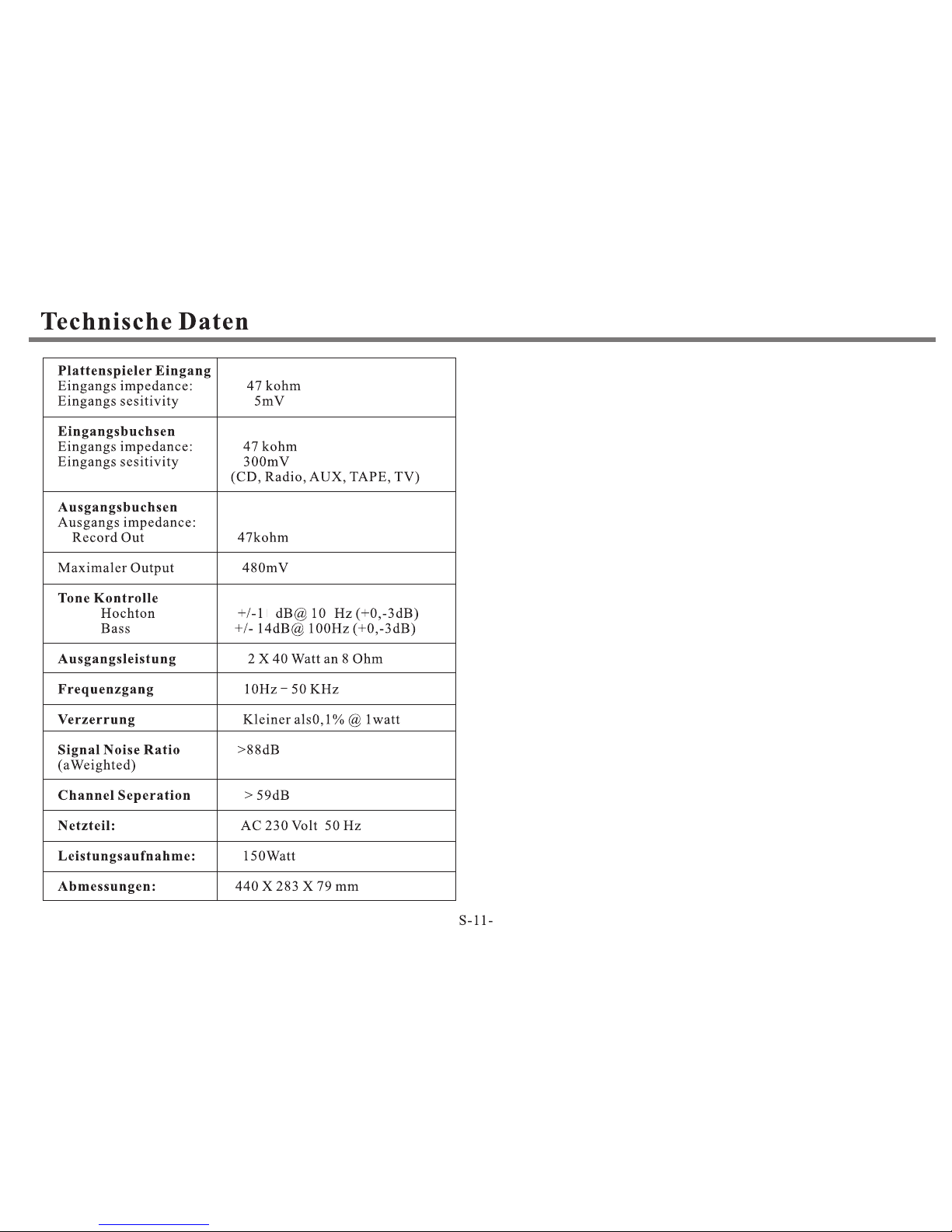
SPECIFICATIONS
(CD, TU NE R, AU X, TAPE, TV)
Less t ha n 0.1 % @ 1 wa tt
440 x 283 x 79mm (with feet)
5mV
300mV
480mV
P21
RECOR OUT
RECOR OUT
+/- 14dB @ 10K Hz (+0, -3dB)
+/- 14dB @ 100 Hz (+0, -3dB)
2 x 40 watts RMS @ 8 ohms
10Hz to 50KHz
> 88dB
AC 230V 50Hz / MAX 150W
DIMENSIONS (WxDxH)
Page 23

 Loading...