

Block EB-2724-2020-0, EB-2724-2040-0, EB-2724-2060-0, EB-2724-2080-0, EB-2724-2120-0 Catalog Page
...Page 1
Power supplies
1.1
1.2
5.1
1.3
2.1
2.2
3.1
3.2
3.3
5.2
4.0
Electronic circuit breakers
2
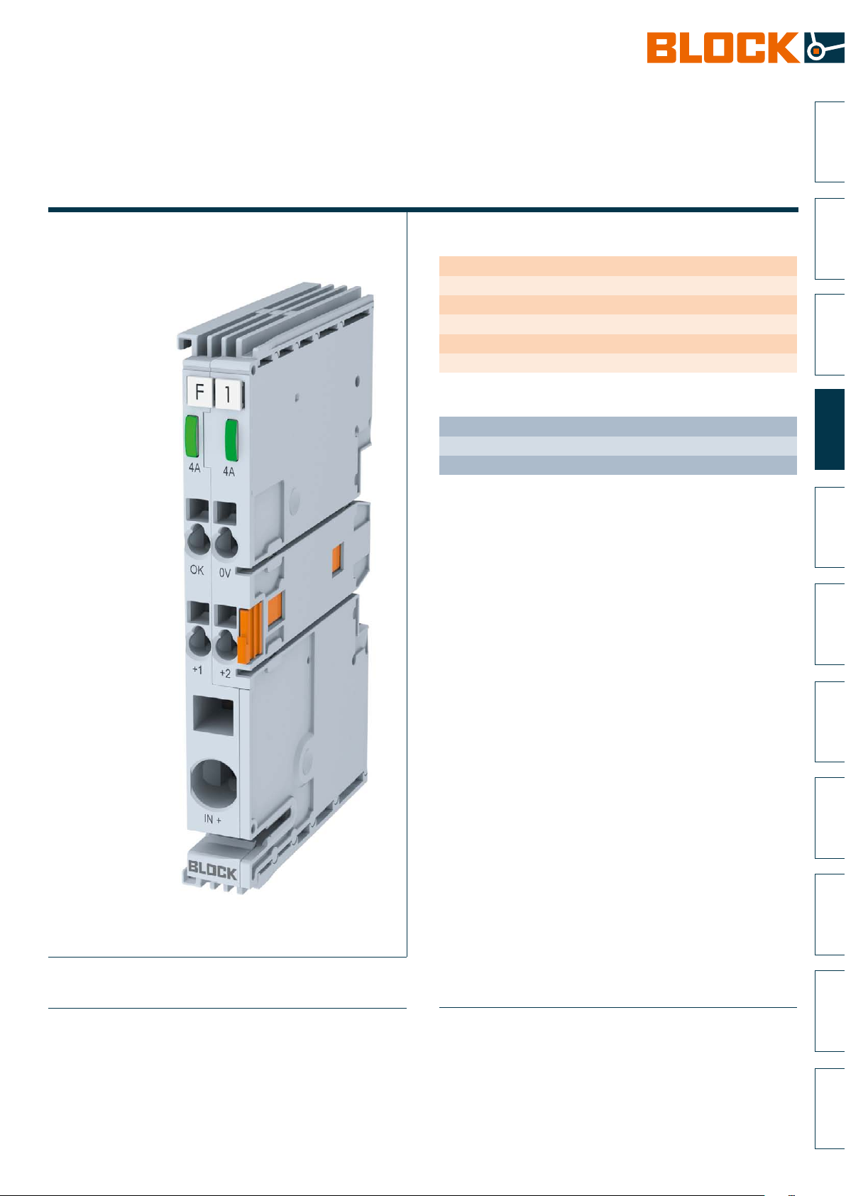
2-Channel circuit breaker
EasyB 2-Channel
General Data
Efficiency up to 99 %
Multi-coloured LED and status display button
Up to 40 fuse channels stackable side by side
With thermomagnetic characteristic
Ambient temperature -25 °C to +55 °C / +70 ° C
Protection index IP 20
Advantages
Compact design - 2 independent channels in 12 mm width
Automatic channel assignment
Additional load outputs through output expanders mountable side by side
Applications
Electronic circuit breaker with thermomagnetic characteristic with alarm signal
forwarded for tripped and switched off channels to the connected channels.
Starter version with fuse for 24 V loads.
StandardsZ
Safety:
EN 60950-1, EN 50178, EN/IEC 60204-1
EMC:
EN 61000-6-2 (interference immunity), EN 61000-6-3 (emitted interference)
CE acc. to 2014/30/EU
Approvals J Z
UL 508 (prepared), UL 2367 (prepared), GL (prepared)
Subject to change
365
Page 2
+
-
2-Channel circuit breaker
EasyB 2-Channel
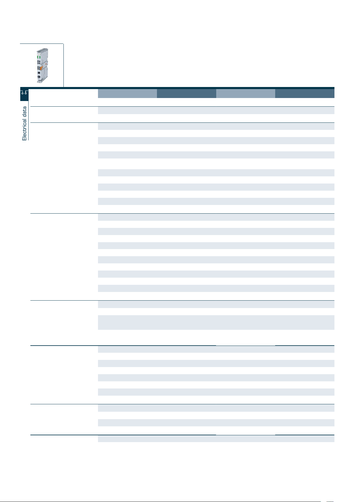
Typ EB-2724-2120-0 EB-2724-2160-0
Special features
Available from
Q2 2017 Q2 2017
Input
Input rated voltage 24 Vdc 24 Vdc
Input voltage range 18 - 30 Vdc 18 - 30 Vdc
Maximal residual ripple of supplied input voltage 3 % 3 %
Max. total input current 12 A 16 A
Max. input current for each pole of terminal 10 A (-), 40 A (+) 10 A (-), 40 A (+)
Required input voltage for turning-on of outputs 17.5 V (Turn-off Threshold 16.7 V),
± 0.7 V
17.5 V (Turn-off Threshold 16.7 V),
± 0.7 V
Max. power losses 0,6 W 0,9 W
Over voltage protection Suppressor diode 33 V Suppressor diode 33 V
Stand-by current 12 mA @ 24 V 12 mA @ 24 V
Power losses in stand-by mode 0,3 W @ 24 V 0,3 W @ 24 V
Turn on capacity 70 mF @ 24 Vdc / 2,5 mm² / 2,5 m 70 mF @ 24 Vdc / 2,5 mm² / 2,5 m
Output
Output rated voltage 24 Vdc 24 Vdc
Output rated current 2 x 6 A 2 x 8 A
Maximum voltage drop between input and output 54 mV 72 mV
Initialization time of module 27 ms 27 ms
Turn-on delay of outputs 0 ms 0 ms
Waiting periode after switch-off of an output 500 ms (Short circuit) … 5 s (Overload) 500 ms (Short circuit) … 5 s (Overload)
Parallel use of outputs Not allowed Not allowed
Serial use of outputs not allowed not allowed
Resistance to reverse feed max. 35 Vdc 35 Vdc
Efficiency 99.0 % 99.0 %
Output limited current - -
Signaling
Bus communication
Collective notification signal bypassed Collective notification signal bypassed
Status indicator LED (red, green, orange) LED (red, green, orange)
Signal output Output status, short circuit proof
high = Channel on, low = Channel off,
fault
Output status, short circuit proof
high = Channel on, low = Channel off,
fault
Signal output (ON/OFF/Reset) - -
Environment
Type of cooling Natural convection Natural convection
Ambient temperature -25 °C … +70 °C -25 °C … +55 °C
Storage temperature -25 °C ... +85 °C -25 °C ... +85 °C
Derating - -
Relative humidity 5 … 96 %, without condensation 5 … 96 %, without condensation
Required minimum spacing (left/right) 0 mm 0 mm
Required minimum spacing (over/under) 30 mm 30 mm
Safety and protection
Protection index
IP 20 IP 20
Safety class
III, without PE connection III, without PE connection
Degree of pollution 2 2
Order numbers
Order Number EB-2724-2120-0 EB-2724-2160-0
+
-
Power supplies
Electronic circuit breakers
2
2-Channel circuit breaker
EasyB 2-Channel
Typ EB-2724-2020-0 EB-2724-2040-0 EB-2724-2060-0 EB-2724-2080-0
Special features
Available from
Input
Input rated voltage 24 Vdc 24 Vdc 24 Vdc 24 Vdc
Input voltage range 18 - 30 Vdc 18 - 30 Vdc 18 - 30 Vdc 18 - 30 Vdc
Maximal residual ripple of supplied input voltage 3 % 3 % 3 % 3 %
Max. total input current 2 A 4 A 6 A 8 A
Max. input current for each pole of terminal 10 A (-), 40 A (+) 10 A (-), 40 A (+) 10 A (-), 40 A (+) 10 A (-), 40 A (+)
Required input voltage for turning-on of outputs 17.5 V (Turn-off Threshold 16.7 V),
Max. power losses 0,4 W 0,4 W 0,4 W 0,4 W
Over voltage protection Suppressor diode 33 V Suppressor diode 33 V Suppressor diode 33 V Suppressor diode 33 V
Stand-by current 12 mA @ 24 V 12 mA @ 24 V 12 mA @ 24 V 12 mA @ 24 V
Power losses in stand-by mode 0,3 W @ 24 V 0,3 W @ 24 V 0,3 W @ 24 V 0,3 W @ 24 V
Turn on capacity 70 mF @ 24 Vdc / 2,5 mm² / 2,5 m 80 mF @ 24 Vdc / 2,5 mm² / 2,5 m 80 mF @ 24 Vdc / 2,5 mm² / 2,5 m 80 mF @ 24 Vdc / 2,5 mm² / 2,5 m
Output
Output rated voltage 24 Vdc 24 Vdc 24 Vdc 24 Vdc
Output rated current 2 x 1 A 2 x 2 A 2 x 3 A 2 x 4 A
Maximum voltage drop between input and output 24 mV 29 mV 33 mV 34 mV
Initialization time of module 27 ms 27 ms 27 ms 27 ms
Turn-on delay of outputs 0 ms 0 ms 0 ms 0 ms
Waiting periode after switch-off of an output 500 ms (Short circuit) … 5 s (Overload) 500 ms (Short circuit) … 5 s (Overload) 500 ms (Short circuit) … 5 s (Overload) 500 ms (Short circuit) … 5 s (Overload)
Parallel use of outputs Not allowed Not allowed Not allowed Not allowed
Serial use of outputs not allowed not allowed not allowed not allowed
Resistance to reverse feed max. 35 Vdc 35 Vdc 35 Vdc 35 Vdc
Efficiency 99.0 % 99.0 % 99.0 % 99.0 %
Output limited current - - - -
Signaling
Bus communication
Status indicator LED (red, green, orange) LED (red, green, orange) LED (red, green, orange) LED (red, green, orange)
Signal output Output status, short circuit proof
Signal output (ON/OFF/Reset) - - - -
Environment
Type of cooling Natural convection Natural convection Natural convection Natural convection
Ambient temperature -25 °C … +70 °C -25 °C … +70 °C -25 °C … +70 °C -25 °C … +70 °C
Storage temperature -25 °C ... +85 °C -25 °C ... +85 °C -25 °C ... +85 °C -25 °C ... +85 °C
Derating - - - -
Relative humidity 5 … 96 %, without condensation 5 … 96 %, without condensation 5 … 96 %, without condensation 5 … 96 %, without condensation
Required minimum spacing (left/right) 0 mm 0 mm 0 mm 0 mm
Required minimum spacing (over/under) 30 mm 30 mm 30 mm 30 mm
Safety and protection
Protection index
Safety class
Degree of pollution 2 2 2 2
Order numbers
Order Number EB-2724-2020-0 EB-2724-2040-0 EB-2724-2060-0 EB-2724-2080-0
Q2 2017 Q2 2017 Q2 2017 Q2 2017
17.5 V (Turn-off Threshold 16.7 V),
± 0.7 V
Collective notification signal bypassed Collective notification signal bypassed Collective notification signal bypassed Collective notification signal bypassed
high = Channel on, low = Channel off,
fault
IP 20 IP 20 IP 20 IP 20
III, without PE connection III, without PE connection III, without PE connection III, without PE connection
± 0.7 V
Output status, short circuit proof
high = Channel on, low = Channel off,
fault
17.5 V (Turn-off Threshold 16.7 V),
± 0.7 V
Output status, short circuit proof
high = Channel on, low = Channel off,
fault
17.5 V (Turn-off Threshold 16.7 V),
± 0.7 V
Output status, short circuit proof
high = Channel on, low = Channel off,
fault
Subject to change
366
Page 3
+
-
Power supplies
1.1
1.2
5.1
1.3
2.1
2.2
3.1
3.2
3.3
5.2
4.0
Electronic circuit breakers
2
2-Channel circuit breaker
EasyB 2-Channel
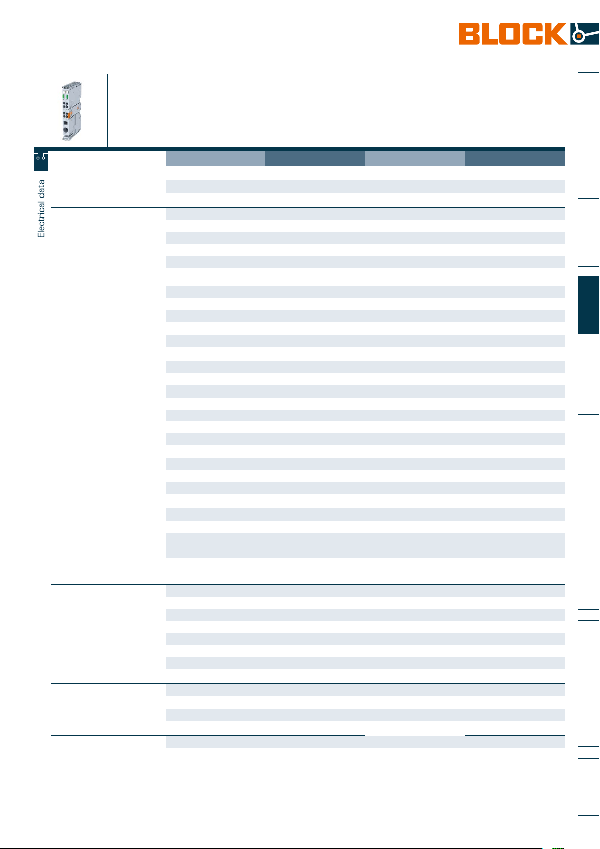
Typ EB-2724-2120-0 EB-2724-2160-0
Special features
Available from
Input
Input rated voltage 24 Vdc 24 Vdc
Input voltage range 18 - 30 Vdc 18 - 30 Vdc
Maximal residual ripple of supplied input voltage 3 % 3 %
Max. total input current 12 A 16 A
Max. input current for each pole of terminal 10 A (-), 40 A (+) 10 A (-), 40 A (+)
Required input voltage for turning-on of outputs 17.5 V (Turn-off Threshold 16.7 V),
Max. power losses 0,6 W 0,9 W
Over voltage protection Suppressor diode 33 V Suppressor diode 33 V
Stand-by current 12 mA @ 24 V 12 mA @ 24 V
Power losses in stand-by mode 0,3 W @ 24 V 0,3 W @ 24 V
Turn on capacity 70 mF @ 24 Vdc / 2,5 mm² / 2,5 m 70 mF @ 24 Vdc / 2,5 mm² / 2,5 m
Output
Output rated voltage 24 Vdc 24 Vdc
Output rated current 2 x 6 A 2 x 8 A
Maximum voltage drop between input and output 54 mV 72 mV
Initialization time of module 27 ms 27 ms
Turn-on delay of outputs 0 ms 0 ms
Waiting periode after switch-off of an output 500 ms (Short circuit) … 5 s (Overload) 500 ms (Short circuit) … 5 s (Overload)
Parallel use of outputs Not allowed Not allowed
Serial use of outputs not allowed not allowed
Resistance to reverse feed max. 35 Vdc 35 Vdc
Efficiency 99.0 % 99.0 %
Output limited current - -
Signaling
Bus communication
Status indicator LED (red, green, orange) LED (red, green, orange)
Signal output Output status, short circuit proof
Signal output (ON/OFF/Reset) - -
Environment
Type of cooling Natural convection Natural convection
Ambient temperature -25 °C … +70 °C -25 °C … +55 °C
Storage temperature -25 °C ... +85 °C -25 °C ... +85 °C
Derating - -
Relative humidity 5 … 96 %, without condensation 5 … 96 %, without condensation
Required minimum spacing (left/right) 0 mm 0 mm
Required minimum spacing (over/under) 30 mm 30 mm
Safety and protection
Protection index
Safety class
Degree of pollution 2 2
Order numbers
Order Number EB-2724-2120-0 EB-2724-2160-0
Q2 2017 Q2 2017
± 0.7 V
Collective notification signal bypassed Collective notification signal bypassed
high = Channel on, low = Channel off,
fault
IP 20 IP 20
III, without PE connection III, without PE connection
17.5 V (Turn-off Threshold 16.7 V),
± 0.7 V
Output status, short circuit proof
high = Channel on, low = Channel off,
fault
Subject to change
367
Page 4
30
Electronic circuit breaker with
thermomagnetic characteristic
ECONOMY SMART
General Data
Nominal input voltage 12 / 24 / 48 Vdc
Output channels 2 / 4 / 8
Tripping current 1 - 6 A / 2 - 10 A
Thermomagnetic characteristic
Ambient temperature -25 °C to +70 °C
Protection index IP 20
Efficiency typ. 99 %
Advantages
Adjustable tripping current for each output channel via current selector
switch
Ability to turn-on high load capacitance at each channel
Sequential and load-dependent switching-on of channels
Comprehensive single-channel-diagnostics and remote switching on/off of
each output channel via 2-wire-interface
LED signalisation and remote request for each output channel
Group alarm contact
Applications
ECONOMY SMART circuit breakers with a thermomagnetic characteristic
represent an economical alternative to the classic circuit breaker. They also
ensure reliable tripping even in the case of high line resistance. This makes the
circuit breakers ideal for use in standard machine production. The electronic
circuit breaker distributes and monitors the load current over several current
circuits. Overloads and short circuits on an output are reliably recognized. The
electronics permit brief current peaks and switch longer overloads off. The
rated current for each output can be individually set with a current selector
switch accessible from the front. The outputs are activated depending on
the time delay and load to avoid an overload current. If the rated current
is exceeded for a certain amount of time, the output will be switched off
automatically and can be reactivated after a waiting time (thermal relaxation)
using the pushbutton or the remote signal input S1. The pushbutton can also
be used to switch the output manually. It is possible to read out the state of
each output using the three signal contacts. The state of each output is also
indicated with a multi-colored LED.
StandardsZ
Approvals o J U # Z
Electronic circuit breaker
UL 508, UL 2367
Safety:
EN 60950-1, EN 50178,
EN/IEC 60204-1
EMC:
EN 61000-6-2, EN 61000-6-3
Safety extra-low voltage (SELV/PELV):
IEC 60364-4-41 (DIN VDE 0100-410)
CE acc. to 2004/108/EG (EMC-Directive)
UL 2367 (E-File: E356250)UL 508 (E-File: E219022)GL
Power supplies
Electronic circuit breakers
2
2-Channel circuit breaker
EasyB 2-Channel
Typ
EB-2724-2020-0 max 2,5 mm² (2 x "+") max. 16 mm² max. 2,5 mm²
EB-2724-2040-0 max 2,5 mm² (2 x "+") max. 16 mm² max. 2,5 mm²
EB-2724-2060-0 max 2,5 mm² (2 x "+") max. 16 mm² max. 2,5 mm²
EB-2724-2080-0 max 2,5 mm² (2 x "+") max. 16 mm² max. 2,5 mm²
EB-2724-2120-0 max 2,5 mm² (2 x "+") max. 16 mm² max. 2,5 mm²
EB-2724-2160-0 max 2,5 mm² (2 x "+") max. 16 mm² max. 2,5 mm²
Terminals output, (spring clamp
terminal)
Terminals input, (spring clamp
terminal)
Dimension pictures
Terminals signalling, (spring clamp
terminal)
Mounting position
horizontal for
standard rail DIN TS35
horizontal for
standard rail DIN TS35
horizontal for
standard rail DIN TS35
horizontal for
standard rail DIN TS35
horizontal for
standard rail DIN TS35
horizontal for
standard rail DIN TS35
Weight
0.039 kg
0.039 kg
0.039 kg
0.039 kg
0.039 kg
0.039 kg
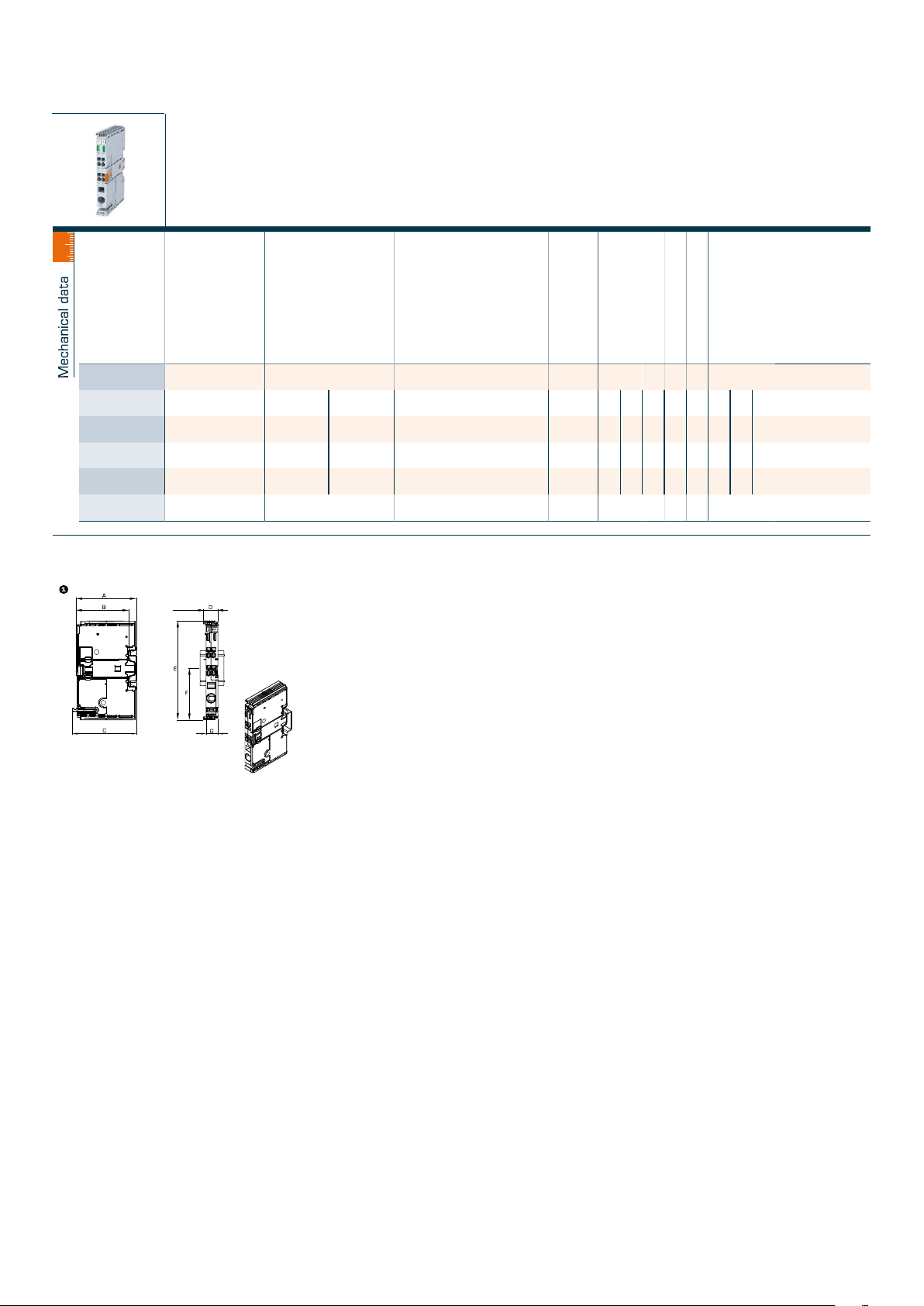
Dimension picture (in mm)
A B C D E F G
61.2 53.7 64.5 14.8 99.3 51.7 12
1
61.2 53.7 64.5 14.8 99.3 51.7 12
1
61.2 53.7 64.5 14.8 99.3 51.7 12
1
61.2 53.7 64.5 14.8 99.3 51.7 12
1
61.2 53.7 64.5 14.8 99.3 51.7 12
1
61.2 53.7 64.5 14.8 99.3 51.7 12
1
Subject to change
368
 Loading...