

Page 1
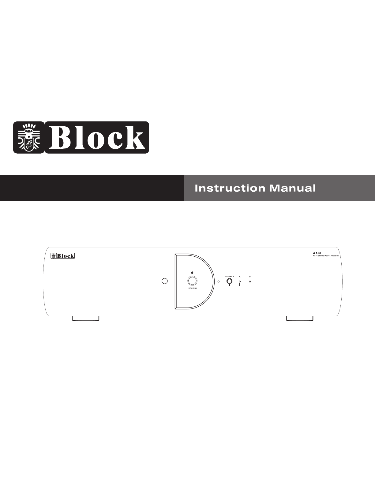
Hi-Fi Stereo Power Amplifier A 100
Bedienungsanleitung
HI-FI Stereo Voll-Verstärker A100
11--201--10
Page 2

S-1-
Anleitung
Herzlichen Glückwunsch zu Ihrem Kauf! Ihr neuer Verstärker A 100
ist entwickelt worden, um den Ansprüchen eines High – End
Produktes zu entsprechen und darauf ausgelegt, Ihnen über viele
Jahre ungetrübten Klanggenuss zu bereiten!
Nehmen Sie sich die Zeit, die Anleitung sorgfältig durchzulesen,
damit Sie Ihren Verstärker fehlerfrei anschließen können!
Anleitung & Inhalt
Inhalt
Anleitung und Inhalt - -------1
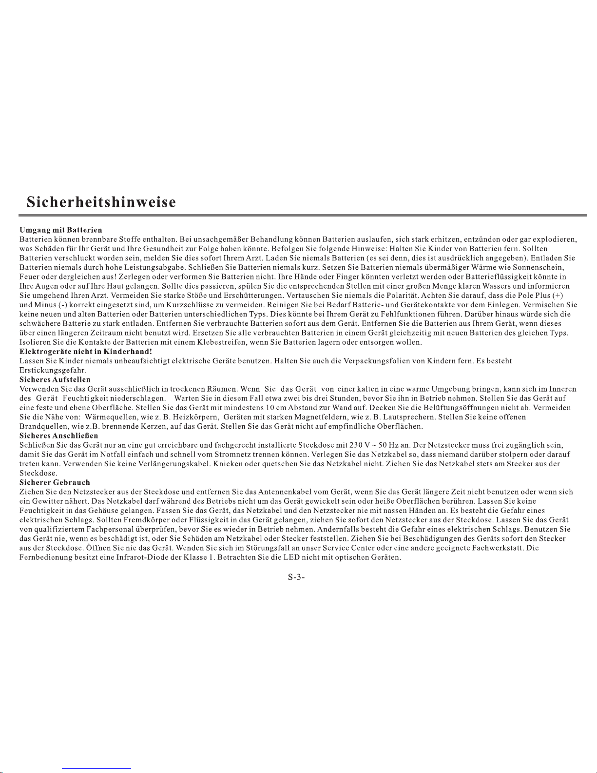
Sicherheitshinweise---------------------------------------------------2-4
Fernbedienung------------------------------------------------------------5
Bedienung am Gerät------------------------------------------------------6
Anschlüsse am Gerät-----------------------------------------------------7
Installation & Anschluss-------------------------------------------------8
Problembehebung--------------------------------------------------------9
Technische Daten--------------------------------------------------------10
----------------------------------------------
Page 3
Page 4
Page 5
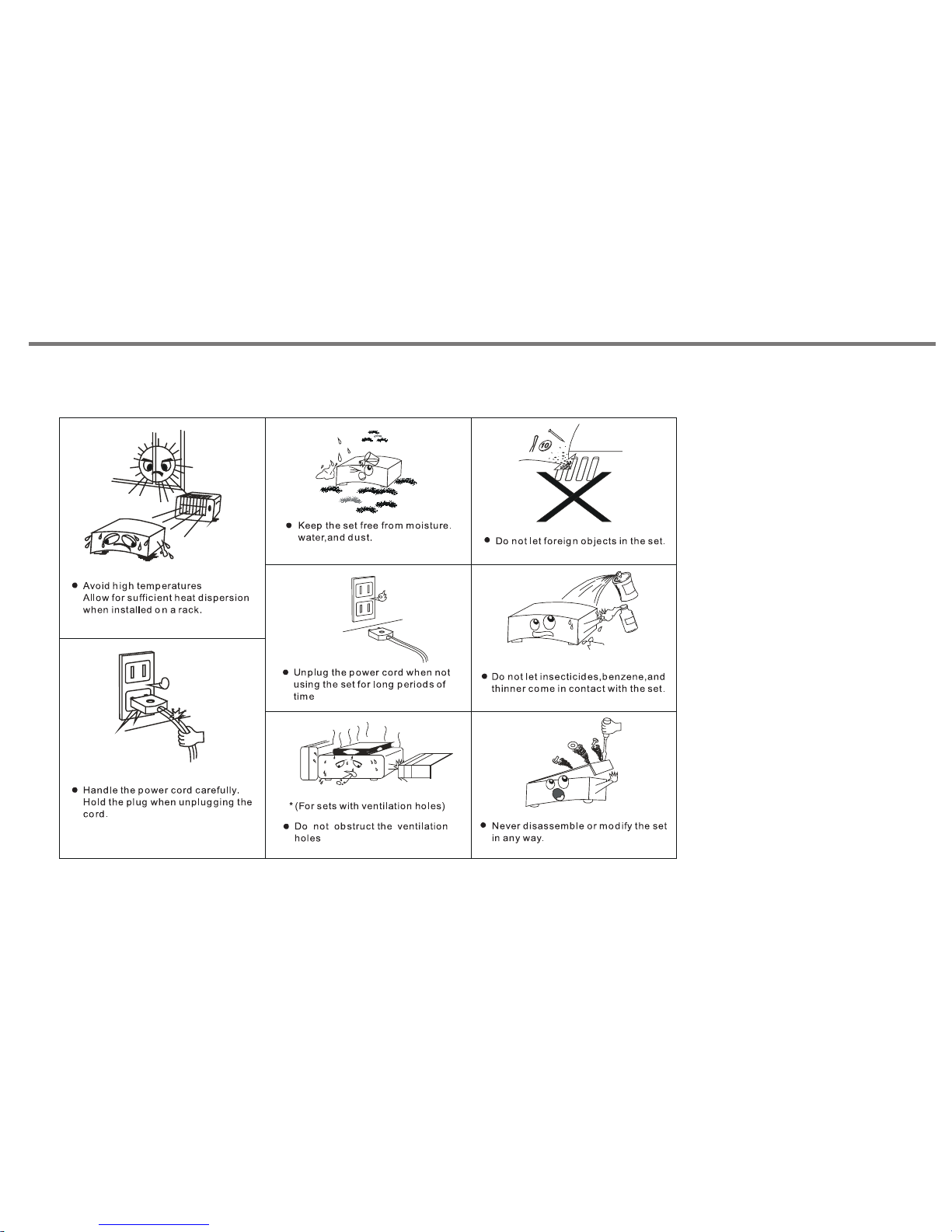
Sicherheitshinweise
S-4-
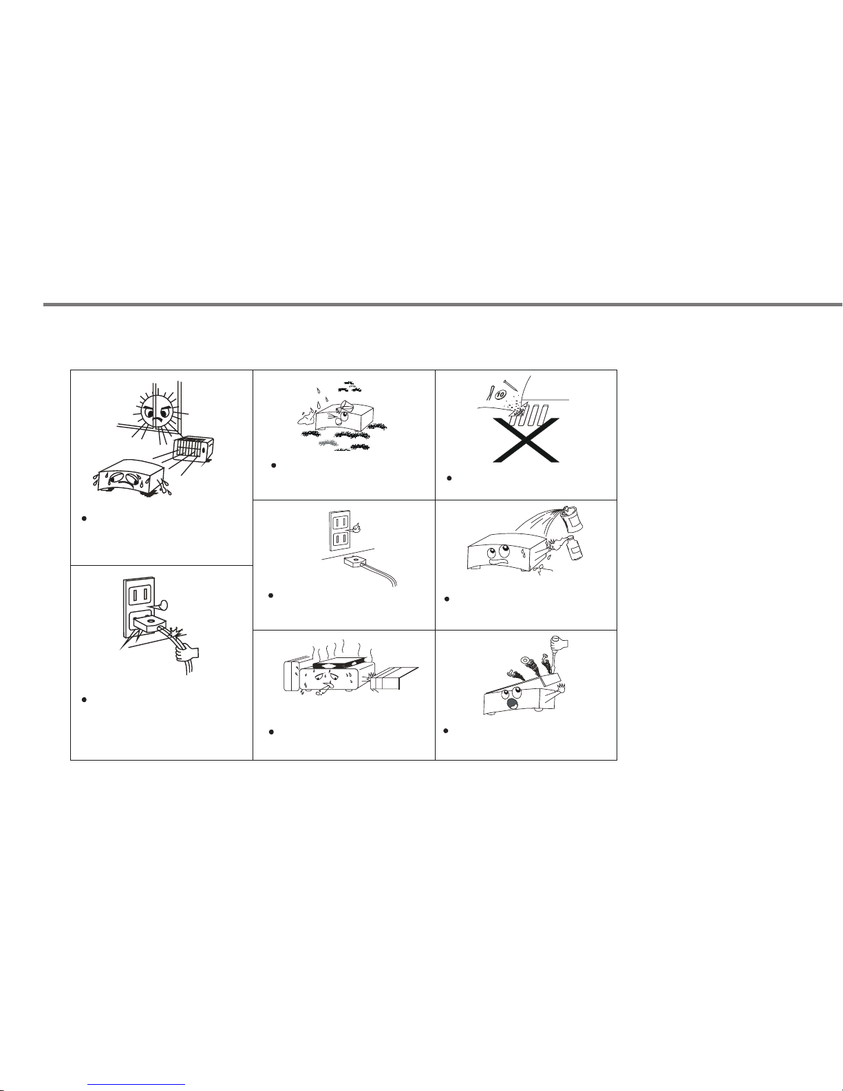
Bit te halt en Sie da s Gerät f ern von
Hit ze- que llen. S orgen Sie für
gen ügend L uftzi rkula tion be i dem
Ein bau in ei nem Rac k
Beh andel n Sie das S tromk abel mi t
Vorsicht
Hal ten Sie d as Gerä t fern vo n
Feu chtig keit
Ach ten Sie d arauf , dass ke ine
Geg enstä nde ins G erät fa llen
Neh men Sie d as Gerä t vom Net z, wenn e s
lan ge Zeit n icht ge nutzt w ird
Ach ten Sie d arauf , dass ke ine Spr ays ode r
Che mie an Ih r Gerät k ommen t
Ach ten Sie d arauf , dass Ih r Gerät n icht
abg edeck t wird
Ach ten Sie d arauf , dass da s Gerät n ur von
aut orisi erten P erson en geöffnet w ird
Page 6
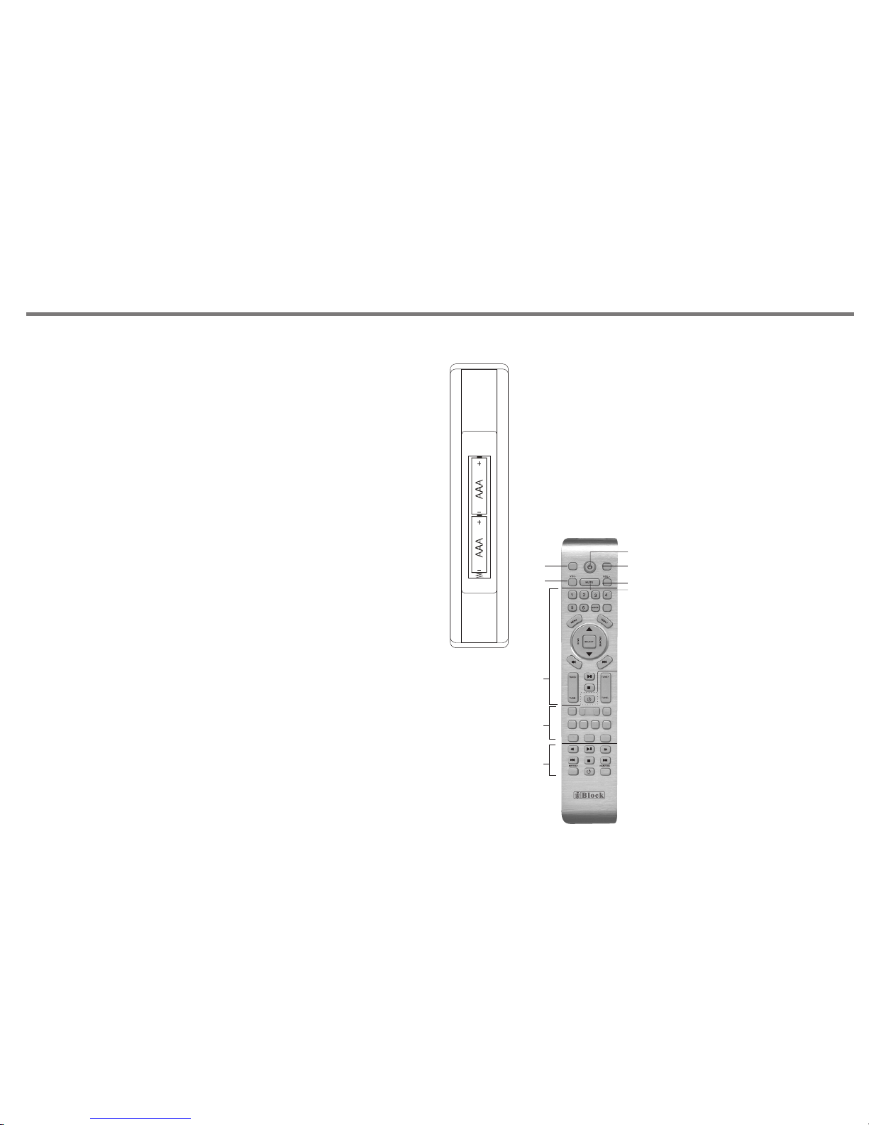
1. Nehmen Sie die Batterien aus
ihrer Verpackung
2. Legen Sie die 2 „AAA“ Batterien
unter Beachtung der Polarität
seitenrichtig ein.
3. Wenn die Distanz zwischen der
Fernbedienung und dem Gerät
abnimmt, liegt das an der Ladung
der Batterien. In diesem Fall
entnehmen Sie die Batterien und
legen Sie neue ein.
Bedien ung C 100
CD STANDBY
RADIO STANDBY
AMP STANDBY
SPK A/B SPK A+B
IR100
INFO
MEMORY
P-MODE
F-SCAN
STEREO
MONO
AM
PR+
PR-
FM
INFO
R100
AUTO+
AUTO-
(FUNCTIO N) (INPUT)
1
2
3
4
5
6
1. Ändern Sie den Lautsprecher
eingang von Lautsprecher A
zu Lautsprecher B
2. Standby. Mit dieser Taste schalten
sie das Gerät an und aus.
3. Mit dieser Taste können sie beide
Lautsprecher A/B einschalten.
4. Mit dieser Taste stellen sie das
Gerät lauter
5. Mit dieser Taste stellen sie das
Gerät leiser
6. Stumm Taste –Mute-
Bedien ung R 100
Bedien ung IR 100
S-5-
Fernbedienung
Sie können Ihren A 100 über die Systemfernbedienung
(optional) fern bedienen. Richten Sie von Ihrer Sitzposition
aus die Fernbedienung in Richtung Ihres Gerätes.
Achtung:
- Wenn sich ein Hindernis zwischen der Fernbedienung und
Ihrem Gerät befindet, kann das die Bedienung
beeinträchtigen.
-Wenn Sie andere Fernbedienungen oder Sender in der
Nähe benutzen, kann das ebenfalls zu Störungen führen.
-Achten Sie darauf, dass Sie die Batterien richtig einlegen
Polarisierung plus zu + minus zu -
-Benutzen Sie zwei gleiche Alkali Batterien
-Aufladbare Batterien können benutzt werden, wir raten
jedoch davon ab.
-Entfernen Sie die Batterien, wenn die Fernbedienung
längere Zeit nicht benutzt wird (6 Monate oder länger)
-Entsorgen Sie Ihre Altbatterien nur in der dafür
vorgesehenen Wertstoffentsorgung (bei Ihrem Händler)
Wirkungsbereich der Fernbedienung
-Die Reichweite der Fernbedienung beträgt ca. 7 Meter.
Sie sollte auf das Infrarotfenster des Gerätes gerichtet
werden.
Dabei ist eine seitliche Abweichung von 30 Grad möglich.
Batterien einlegen
Page 7
Bedienung am Gerät
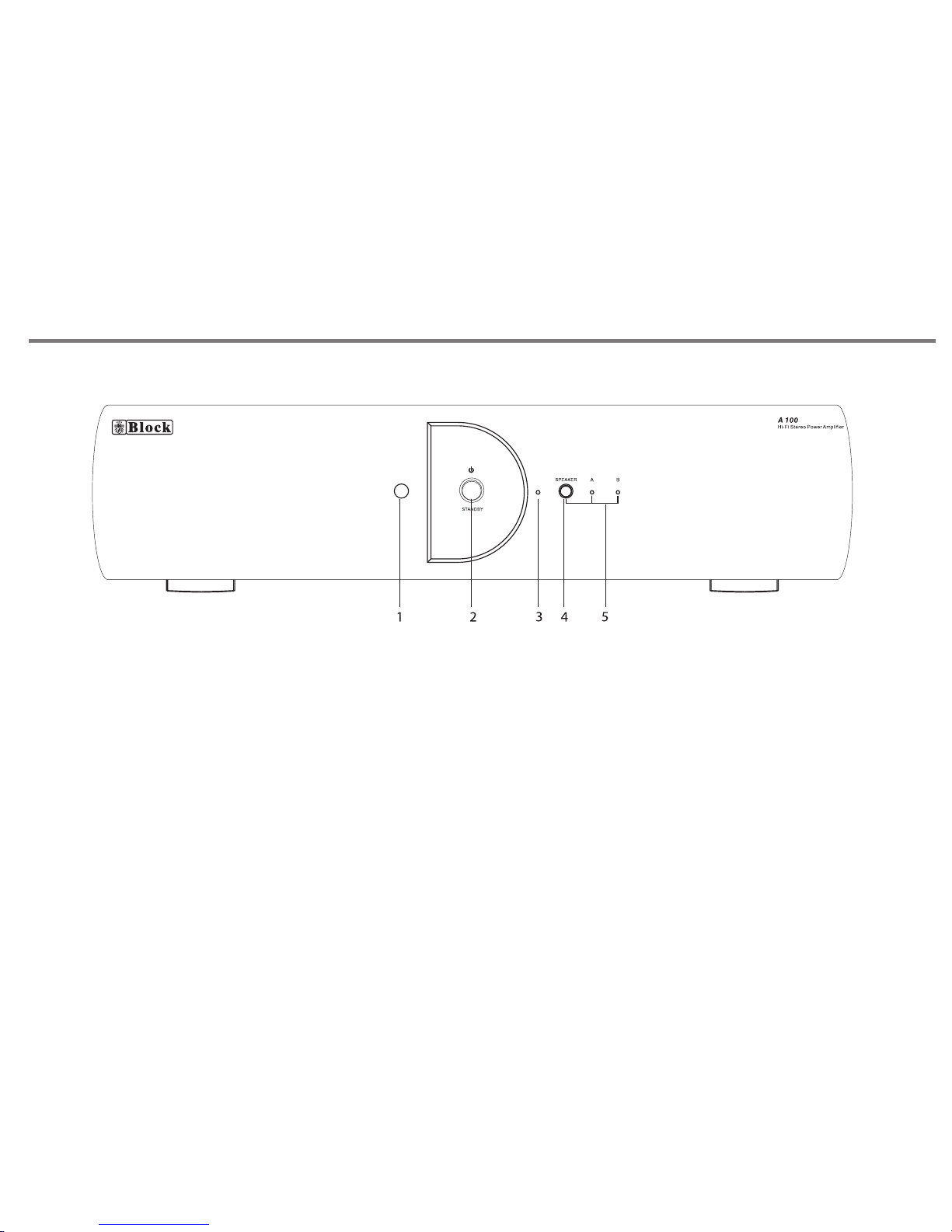
1.Fernbedienung Sensor
2.Standby Taste: Mit dieser Taste können sie das Gerät an- und ausschalten.
3.LED Lampe: Die Lampe leuchtet rot, wenn das Gerät ausgeschaltet ist.
4.Lautsprecher
5.Lautsprecher LED Lampe
S-6-
Page 8
FUSE: T 4A 250V
8
8
1 2
3
4
5
6
7
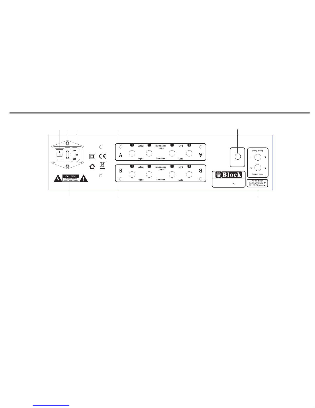
1. Power Schalter: Dieser Hauptschalter schaltet das
Gerät ein oder aus.
Beachten Sie: Wenn dieser Schalter auf aus steht,
ist das Gerät komplett vom Netz getrennt.
2. Sicherungshalter: In diesem Halter befindet sich
eine 20mm T 0,5A Sicherung.
Wichtig!
Beim Wechseln der Sicherung nehmen Sie das Netzkabel
ab.
3. Netzkabelanschluss: Gehen Sie sicher, dass das Netzkabel
nicht beschädigt wird
4. Warnhinweise: Die Schilder zeigen an, dass es um hohe
Spannungen geht. (näheres auf Seite 2)
Anschlüsse am Gerät
S-7-
5. Lautsprecherausgang A: Achten sie darauf, dass +/ am Lautsprecher sowie am Gerät übereinstimmen.
6. Lautsprecherausgang B: Achten sie darauf, dass +/ am Lautsprecher sowie am Gerät übereinstimmen
7. Analoger Signal Eingang.
8.
Mode l: A 100
Hi-F i Stereo P ower Am plifi er
Powe r Ratin g: AC 230 V 50Hz
Max Po wer Con sumpt ion: 50 0W
Bala nce
R
L
Bala nce
R
L
8
Page 9
FUSE:T 5 00mA 250 V
Mode l: P 100
Hi-F i Stere o Pream plifi er
Powe r Ratin g: AC 230V 5 0Hz
Max Po wer Con sumpt ion: 10 W
MM
MC
CONTROL
P
t
r
c
e
e
s
l
s
e
t
s
o
R 100
AM/FM RDS PLL Tuner
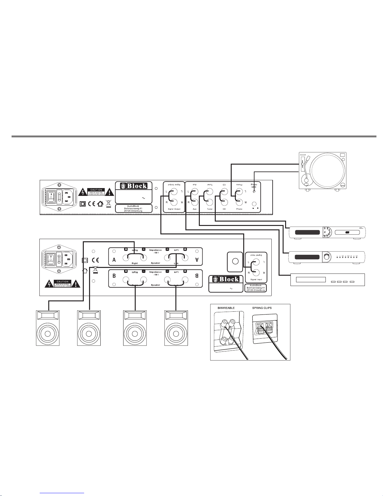
Installation / Anschluss
P 100 (Vor-Verstärker)
CD Spi eler
Radi o
Ande re Audio Q uelle n
A 100 (Voll-Verstärker)
Lau tspre chera nschl uss
S-8-
FUSE: T4 A 250V
8
8
Model : A 100
Hi-Fi S tereo P ower Am plifi er
Power R ating : AC 230V 5 0Hz
Max Pow er Cons umpti on: 500 W
Balan ce
R
L
Balan ce
R
L
Page 10

S-9-
Problembehebung
Problembehebung
Um den Verstärker zu säube rn, nehmen Sie bitte ein en staubfreien und tro ckenen Lappen.
Bitte ke ine chemischen oder alkoh olischen Mittel benu tzen.
Um das Ger ät zu verschicken, benutz en Sie bitte die dafür vorgesehene
Verpa ckung.
Wenn das Gerät in eine r sta ubigen Umgebung genu tzt wird, sollte esin be stimmten
Zeitab schnitten zur Reinigung i n den Service gegeben
werden , da so nst eine optimale Kühl ung nicht gegeben ist.
Fehler
Ursache
Schwacher Bass und kein
Stereo
-Die Lautsprecherkabel sind verpolt
angeschlossen. Kontrollieren sie ob+an +
und – an – angeschlossen ist.
Schlechter Klang
-Das Lautsprecherkabel kommt am
Gehäuse an. Bitte beheben!
-Der Bass oder der Hochton ist zu hoch
eingestellt
-Die Lautstärke ist zu hoch eingestellt.
Die Eingangswahl
funktioniert nicht
-Das Gerät ist defekt und muss zum
Service geschickt werden.
Fehler
Ursache
Kein Strom
-
-Das Kabel steckt nicht richtig
-Eine Sicherung ist defekt. In diesem
Fall schicken sie das Gerät bitte zu
unserem Service.
-Das Netzkabel ist defekt. Lassen sie
das Kabel ersetzen.
Der Hauptschalter ist nicht an
Kein Ton
- Das Gerät ist nicht angeschaltet
- Die Lautsprecher sind ausgeschaltet
- Die Lautsprecherkabel sind nicht
angeschlossen
- Es ist keine Signalquelle angeschlossen
Kein Ton auf
einem Kanal
-
angeschlossen
-Das Eingangskabel ist defekt
-Die Lautsprecherkabel sind nicht richtig
angeschlossen oder defekt.
-Der Lautsprecher ist defekt.
Das Eingangskabel ist nicht richtig
Lautes Brummen
-
richtig angeschlossen
-Die Erdung vom Plattenspieler ist defekt
oder nicht richtig angeschlossen.
-Die Erdung ist nicht korrekt angeschlossen.
-Der Tonabnehmer ist nicht korrekt
angeschlossen
-Ein Kassettenspieler ist zu nah am
Fernseher
angeschlossen
Das Eingangskabel ist defekt oder nicht
Page 11
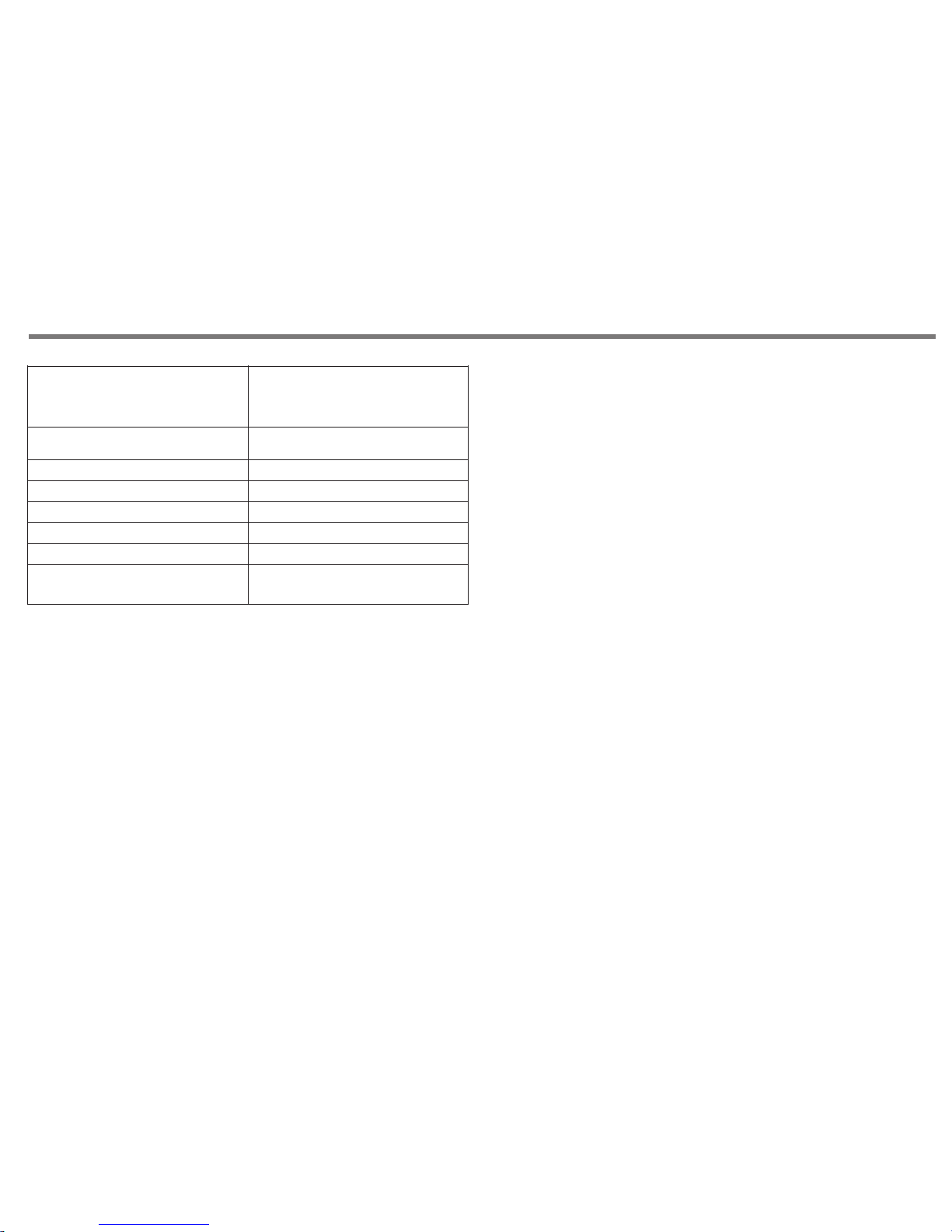
850mV
kleine r als 0.05% @ 1 watt
2 x 100 Watts RMS @ 8 ohm
> 95dB
440 x 330 x 117
Max 500W
10Hz bis 3 5kH z (-3dB )
> 65dB
S-10-
Technische Daten
Eingang – Le vel - Input
Eingangs Impedanz
Eingangs Empfindlichkeit
Leistung
Frequenzgan g
Verzerr ung
Signal – Rau sch - Ab stand
Kanal - Trennung
Leistung saufnahme
Abmessun gen
47 kOhm
Page 12

INTRODUCTION & CONTENTS
Contents
Introduction & Contents
Safety instructions
Remote control
Front panel controls
Rear panel connections
Making the connections
Installation and position
Tro uble sh ootin g
Specifications
11
12,13
14
15
16
17
18
20
19
Congratulations on purchasing thi s ampl ifier. It has b een deve loped
following an ext ensiv e resear ch and deve lopme nt program that has
culminated in what we regard as an hi-fi product.
We trus t that th is ampl ifier w ill giv e you hou rs of listening pleasure,
and provide years of unparalleled performance.
Please do not operate this product at high vol ume lev els imm ediat ely
after switching on.
Introduction
P11
Page 13
SAFETY INSTRUCTIONS
Safety Instructions
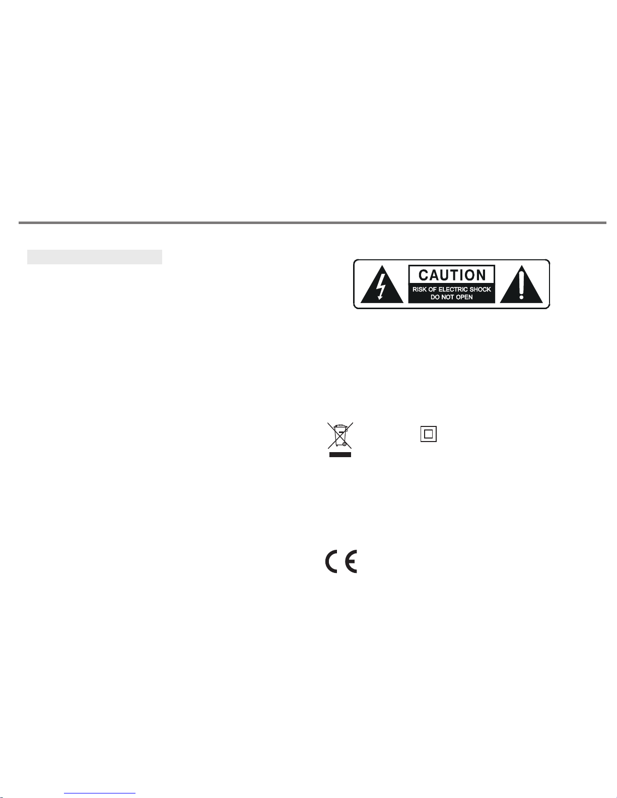
CAUTION: To reduce the risk of e lectr ic sho ck, do no t remove any
cover.
N O U SER- SE R V ICEA B L E PA R T S I NSID E, R E FER A N Y
SERVI CING TO QUALIFIED SERV ICE PER SONNEL.
IMPORTANT SAFETY INST RUCTI ONS
* Read and keep these instructions available for fu ture re feren ce.
* For indoor use only.
* The uni t must only be conne cted to a s uitab le mains power sup ply
using the mains power lead provided.
* To redu ce the risk of fire o r electrical shoc k, do not expo se this
unit to rain or moisture.
* The app aratu s shall n ot be exp osed to d rippi ng or spl ashin g.
* No ob jects filled with liquids, su ch as v ases, shal l be pl aced on
the apparatus.
* Unp lug the unit fro m the wa ll socke t during ligh tning st orms and
when it is not going to be used for a long period of time.
* Tak e care that fore ign objects do not enter, or liqu ids are not
spilled, int o the e nclos ure throug h any openin gs. If this should
happen, refer to qualified servi ce personnel bef ore att empti ng to
use.
* Ensure a dequa te v entil ation - do not cov er t his unit with curtains,
etc.
* Do not in stall near any heat sou rce, su ch as rad iator s, or other
equipment that produces heat.
* Protect the mains power cable from be ing dam aged.
The light ning flash symbo l wi th the arro whead within an equi later al
triangle is int ended to aler t the user to the pres ence of uninsulated
'dangerous voltag e' with in the pr oduct 's enclosure that m ay be
suffi cient t o const itute a r isk of el ectric shock to persons.
The e xclam ation point w ithin an equi later al trian gle is i ntend ed to
alert the u ser to impo rtant o perat ing and mai ntena nce instructions
in the service literature relevant to this a pplia nce.
"Infor mat ion for the c ons umer"
Dispos al of y our old pro duc t
Your p roduct is d esi gned and ma nuf actured w ith h igh quali ty ma terials a nd co mponent s,
which ca n be re cycled an d reu sed.
When thi s cro ssed out wh eel ed bin symb ol is a ttached t o a pro duct i t mea ns th e prod uct i s
covere d by th e Europea n Dir ective 20 02/ 96/EC.
Please m ake y ourself a war e of the loca l col lection s yst em for e lec tri cal an d
electr oni c product s.
Please a ct ac cording t o you r loca rule s and d o not dispo se of y our ol d pro duc ts wit h
your nor mal h ousehol d was te. Th e cor rect disp osa l of your old p rod uct wi ll he lp pr even t
potent ial n egative c ons equence s for t he enviro nme nt and huma n hea lth.
This pro duc t complie s wit h Europea n low v otage (73 /23 /EEC )
and elec tro magneti c com patibil ity ( 89/336/ EEC ) dire cti ves .
A symbol fo r cla ss II ( doubl e ins ulation )
P12
Page 14
SAFETY INSTRUCTIONS
Notes On Use
P13
Page 15
BATTERY INSTALLATION
By using the provided remote control unit th e A 100 can be
controlled from your listening position. To use the r emote
control unit, point it at the REMOTE SE NSOR wi ndow of t he
receiver.
Notes:
-Even if the remote control unit is ope rated w ithin t he
effec tive ra nge, re mote co ntrol o perat ion may be impossible if
there are any obstacles between the unit and the remo te
control.
-If the remote control unit is o perat ed near o ther ap plian ce
which generate infrared rays, or if other re mote co ntrol
devices using infrared rays are used near the unit, i t may
operate incorrectly.
Precautions concerning batteries
-Be sure to insert the batteri es with c orrec t posit ive+ an d
negative - polarities.
-Use batteries of the same typ e. Neve r use different types of
batteries together.
- Rechargeable and non-rechargeable batteries can be used.
Refer to the precautions on their labels.
-When the remote control unit is not to b e used fo r a long
time(more than a month), remove the b atter ies fro m the
remote control unit to prevent them f rom lea king. I f the lea k,
wipe away the liquid inside the battery compartme nt and
replace the batteries with new ones.
-Do not heat or disassemble batteries and never dis pose of
old batteries by throwing them in a fire.
REMOTE CONTROL OP ERATION RAN GE
Use the remote control unit within a range of ab out 7
meters and the angles of up to 30 degrees aiming a t
the remote sensor.
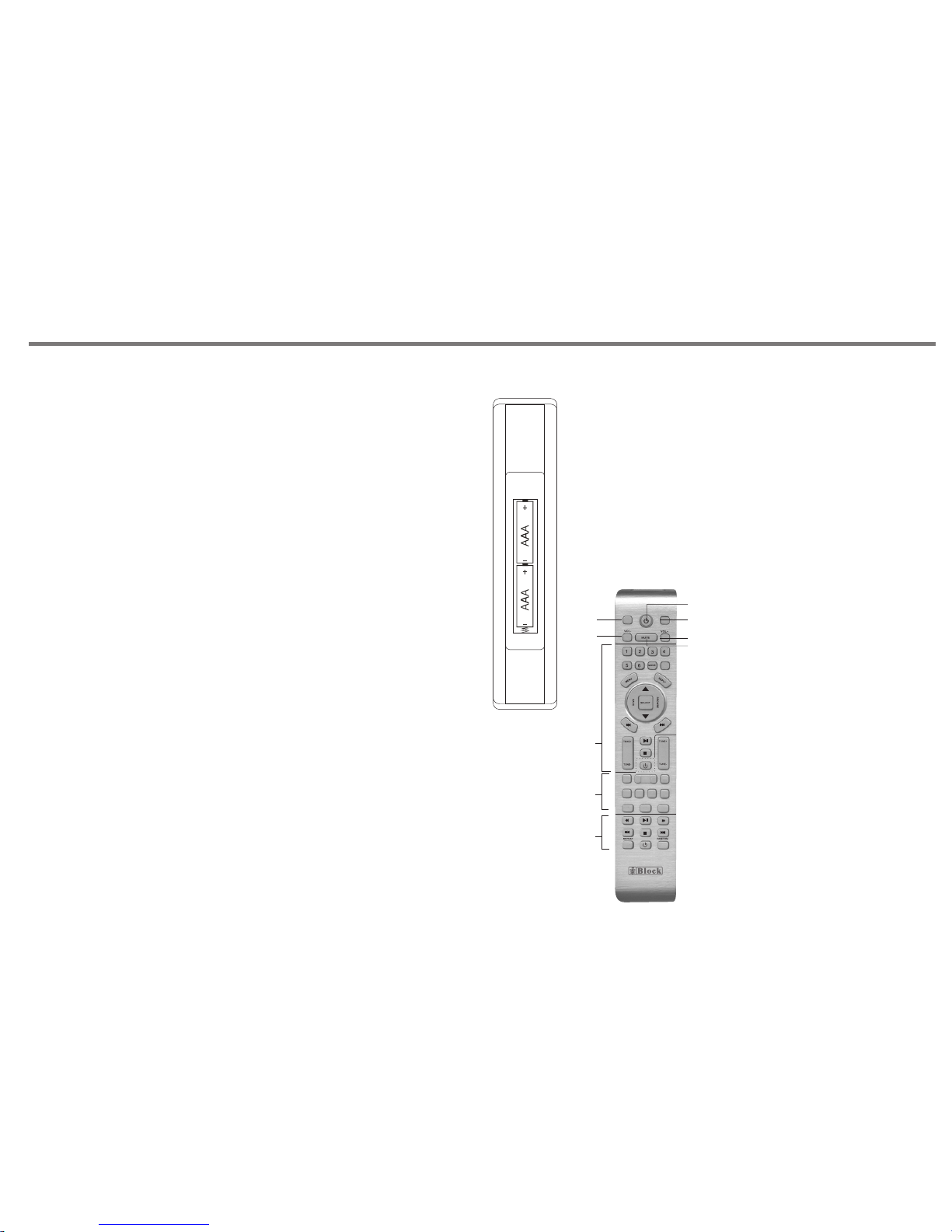
1. Remo ve th e bat ter y compartment cove r.
2. Inse rt tw o "AA A" dr y batteries.
Make su re th at th e bat teries are inserte d wit h the ir
posit ive " +" an d neg ative "-" poles posi tio ned c orrectly.
3. Clos e the c ove r unt il it clicks.
If the di sta nce r equ ired between the rem ote c ont rol u nit and
main un it de cre ase s, the batteries are e xha ust ed. I n this case,
repla ce th e bat ter ies with new one.
REMOTE CONTROL
This pa rt fo r C 100
P14
CD STANDBY
RADIO STANDBY
AMP STANDBY
SPK A/B SPK A+B
IR100
INFO
MEMORY
P-MODE
F-SCAN
STEREO
MONO
AM
PR+
PR-
FM
INFO
R100
AUTO+
AUTO-
(FUNCTIO N) (INPUT)
1
2
3
4
5
6
1. If th e uni t is A 1 00 pow er am pli fier,
press to c han ge output s pea ker
mode. Wi th 2 mo des for sel ect ion,
Speake r A an d Spe aker B.
If the uni t is V 10 0 amplifi er,
press to g o to me nu featur es su ch as ba ss,
treble , bal ance, res et, a nd use
VOL-/+ k ey to a djust the p ara mete r.
2. Stand by ke y
3. If the un it is A 100 p ower ampl ifi er,
press to c han ge output s pea ker mode
to Speak er A+B .
If the uni t is V 10 0 amplifi er,
press to c han ge input so urc e.
4. Volume l eve l down key
(for mod el P 100 and V 10 0)
5. Volume l eve l up key
(for mod el P 100 and V 10 0)
6. Mute ke y
This pa rt fo r R 100
This pa rt fo r IR 10 0
Page 16
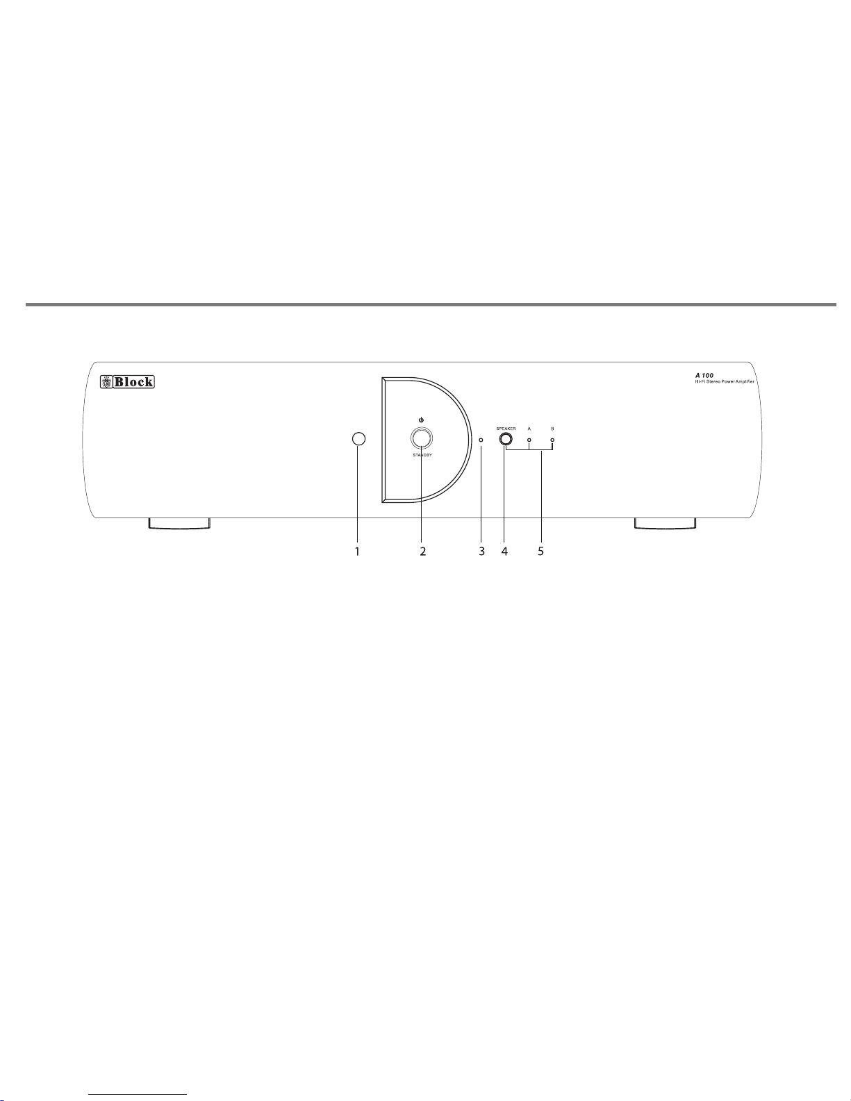
FRONT PANEL CONTROLS
P15
1. REMOTE SENSOR.
2. STAND BY BU TTON. Press this bu tton to t urn to st andby
mode, press again return to no rmal mo de.
3.LED INDICATOR, i t will be t urn on in r ed colo ur when t he unit
is in standby mode.
4. SPEAKER MODE BUTTO N. Press to change speaker output
mode, with 3 modes for selecti on, Spe aker A, Sp eaker B , and
Speaker A+B.
5. SPEAKER MODE LED INDICATOR.
Page 17
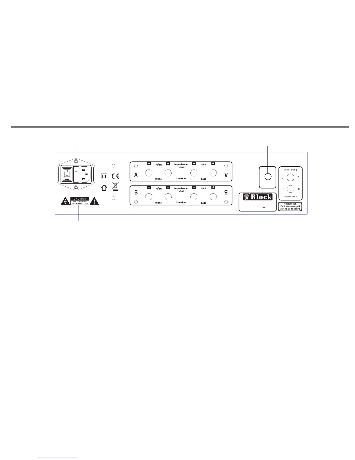
REAR PANEL CONNECTIONS
P16
1. POWER SWITC H: Swit ches ma ins pow er on/o ff to internal
components, however plea se note t hat mai ns powe r is stil l
applied to this unit even though this s witch m ay be off.
2. FUSE HOLDER: fitte d with 20 mm T 4A fu se insi de.
" IMPORTANT:"
Remove the mains plug from the m ains so cket be fore at tempt ing
to check/ replace the f use loc ated on t his fus e holde r.
3. M AIN S CAB LE IN LET JACK : Ple ase ensure that t he in put c abl e strain relief
bush is i nta ct an d has n ot been damaged.
4. WA RNI NG ICONS: Pleas e be aw are t hat t his unit contains hi gh vo lta ges ,
and sho uld n ot be o pen ed, please refer to pa ge 2 of t his m anu al.
5. L OUD SPE AKE R A OU TPUTS . Please en sur e tha t +/- c onn ections are
made pr ope rly b etw een rear of the amplif ier a nd lo uds peakers. Ensu re
wires a re no t fra yed o r tou ching.
6. L OUD SPE AKE R B OUTPUTS . Please ens ure t hat + /- co nnections are
made pr ope rly b etw een rear of the amplif ier a nd lo uds peakers. Ensu re
wires a re no t fra yed o r tou ching.
7. ANALOG SIGNAL INP UT JA CK.
8. BALANCE CONTROL KNOB.
FUSE: T 4A 250V
8
8
1 2
3
4
5
6
7
Mode l: A 100
Hi-F i Stereo P ower Am plifi er
Powe r Ratin g: AC 230 V 50Hz
Max Po wer Con sumpt ion: 50 0W
Bala nce
R
L
Bala nce
R
L
8
Page 18
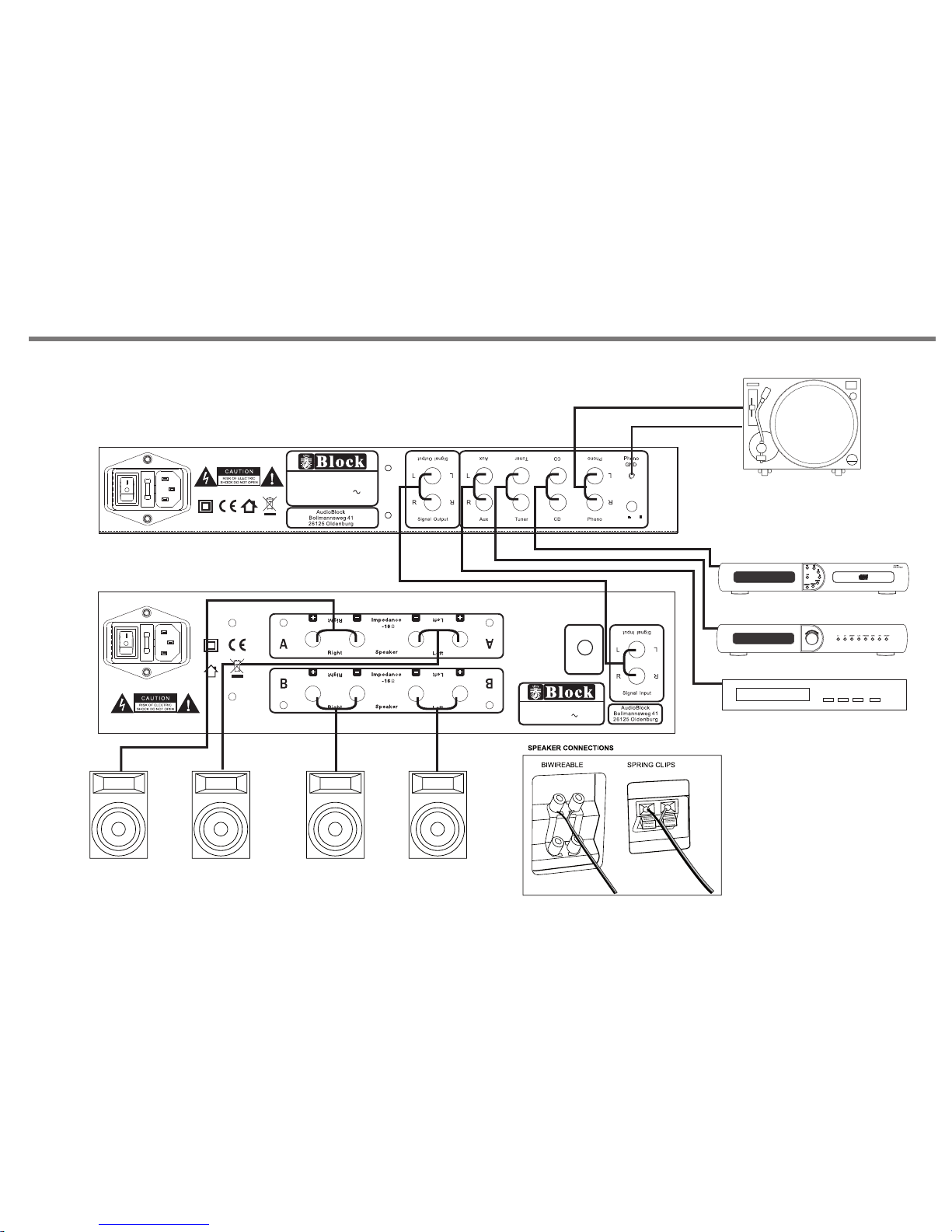
MAKING THE CONNECTIONS
P17
FUSE:T 5 00mA 250 V
Mode l: P 100
Hi-F i Stere o Pream plifi er
Powe r Ratin g: AC 230V 5 0Hz
Max Po wer Con sumpt ion: 10 W
MM
MC
A 100 (Power -Amplif ier)
P 100 (Pr e-Ampli fier)
OTH ER AUDIO S OURCE
TUN ER
CD PL AYER
CONTROL
P
t
r
c
e
e
s
l
s
e
t
s
o
R 100
AM/FM RDS PLL Tuner
FUSE: T4 A 250V
8
8
Model : A 100
Hi-Fi S tereo P ower Am plifi er
Power R ating : AC 230V 5 0Hz
Max Pow er Cons umpti on: 500 W
Balan ce
R
L
Balan ce
R
L
Page 19
INSTALLATION AND POSITION
u n i t
u n i t
P18
Page 20
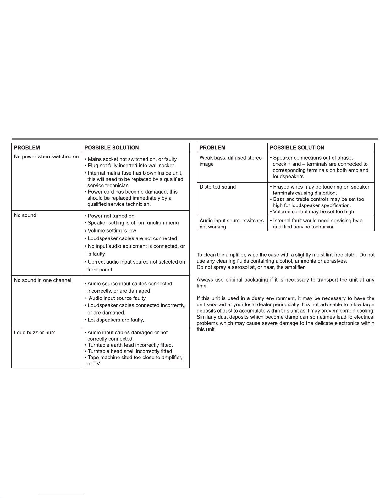
TROUBLE AND SHOOTING
CARE AND MAINTENANCE
P19
Page 21
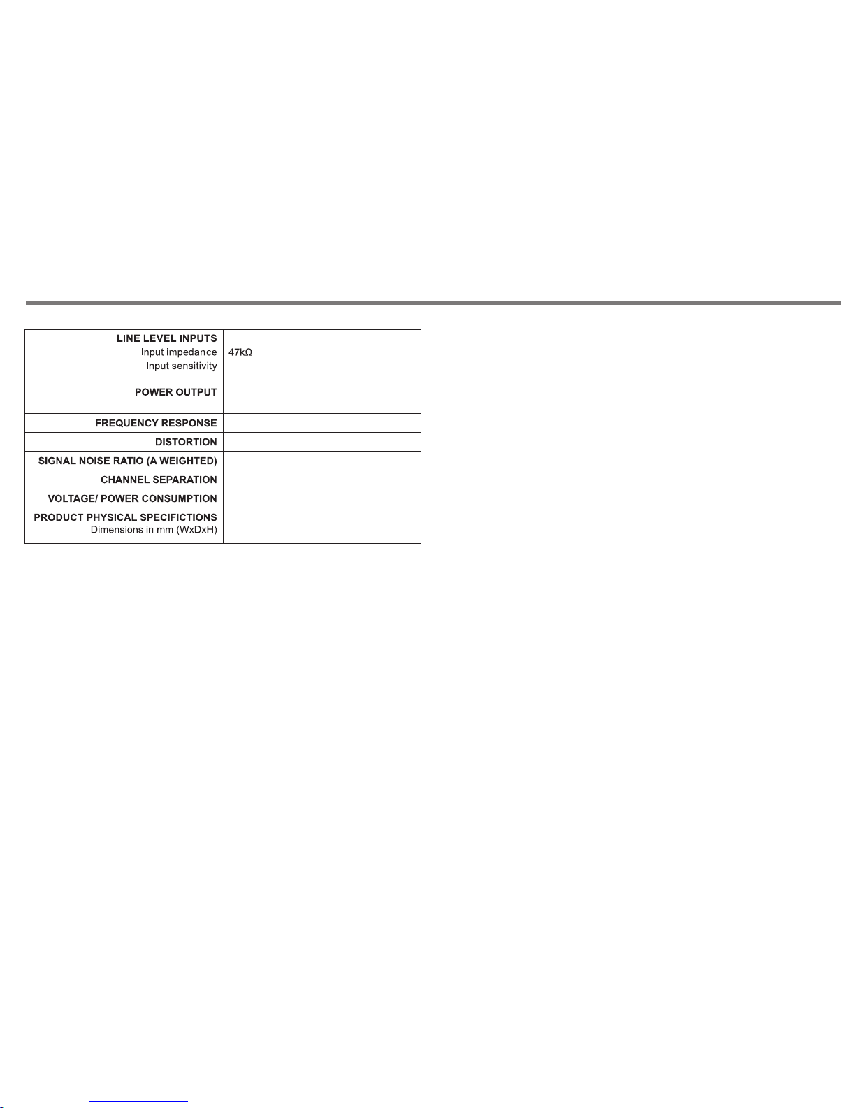
850mV
SPECIFICATIONS
P20
Less th an 0. 05% @ 1 w att
2 x 100 wat ts RM S @ 8 ohm s
> 95dB
440 x 330 x 117mm (with fee t)
Max 500 W
10Hz to 3 5kH z (-3 dB po ints)
> 65dB
Page 22

 Loading...