

Page 1

Assembly & Operation Manual
Blizzard Straight Blade Snowplows
Models 700LD, 760LD, 760 & 800
Page 2

i Table of Contents
Introduction
Congratulations on purchasing the finest
straight blade snowplow available!
Blizzard straight blades are clearing
new trails for innovative design, rugged
durability, quality craftsmanship and
superior performance. Our exclusive
products are manufactured and tested
in Michigan’s Upper Peninsula, the
snow capital of the Midwest. With an
annual snowfall averaging over 250,"
we couldn’t imagine building snow
removal products anywhere else!
Your Blizzard straight blade is equipped
with versatile features designed f or years
of dependable service. The hydraulic
draw latch mounting system positively
aligns the plow for fast installation or
removal. All Blizzard straight blade
snowplows feature an extended moldboard.This unique construction provides
an additional 5" of blade that rolls snow
farther ahead and to the side when
plowing. Now you can move snow
faster, saving fuel and reducing wear
on your truck and plow. Safety features
include full moldboard trip action,
enclosed hydraulics and automatic
cylinder pressure relief.
To ensure years of optimum snowplow
performance, review the contents of this
manual. It contains assembly information, detailed diagrams, complete parts
listings, maintenance guidelines and
troubleshooting tips.
Should you need additional information,
contact your local Blizzard snowplow
dealer.Their knowledgeable staff is well
informed on the latest straight blade
information.They are also your source
for replacement parts, technical assistance and all service repairs.
Comments, suggestions or concerns?
Address all correspondence to:
Blizzard Corporation
Customer Service Department
95 Airpark Boulevard
Calumet, MI 49913
Table of Contents
01 Snowplow Accessories
02 Warning!
03 Snowplow Operation
Assembly Instructions
04 Unpacking & Inspection
05 Moldboard & A-frame Assembly
09 Electrical Assembly - Plow Harness
10 Electrical Assembly - Vehicle Harness
12 Testing The Snowplow
14 Mounting & Dismounting Instructions
Maintenance & Plow Specifications
15 Regular Maintenance
16 Storing Y our Snowplow
17 Plow Specifications
Plow Diagrams & Part Lists
18 Models 700LD, 760LD, 760 & 800 Parts List
22 Models 700LD, 760LD, 760 & 800 Assembly Schematic
24 Manifold Detail with Hydraulic & Electrical Schematics
Electrical Diagrams
25 Molded Plug Pin Locations
26 Plow Harness
27 Plow Harness Wire Schematic
28 Main Lighting Harness - Relay Version
29 Main Lighting Harness - Relay Version Wire Schematic
30 Vehicle Har ness
31 Vehicle Har ness Wire Schematic
32 On/Off Switch Leads & Ground Lead
Torque Specifications
33 Bolts & Hydraulic Adapters
Troubleshooting
34 Troubleshooting Guide
Warranties
36 Limited Consumer Warranty
37 Commercial Warranty
Page 3
Blizzard Snowplow Airfoil
P/N 81041 (700LD & 760LD)
P/N 52093 (760 & 800)
Help channel air flow to
your truck radiator during
the long haul over the road.Mounted front and center, our custom
airfoil redirects air over the top of the b lade and into the grill of your
vehicle.Don’t get stuckon the side of the road! Keep trucking with
this easy-to-install accessory.The airfoil is shipped with complete
mounting hardware.
Blizzard Snowplow
Touch-Up Paint
P/N 61219 (Gloss White)
P/N 63073 (Gloss Black)
Putting your snowplow away for
the winter? Have a deep scratch
to cover? Clean up your blade and
plow parts with our gloss spray
paints. Made to match your original plow equipment, Blizzard
snowplow touch-up paint provides an excellent finish to help keep
your snowplow looking its best.Paint provided in 12 oz.spray cans.
Blizzard Snowplow Rapid
Action Hydraulic Oil
P/N 63070 (Quart)
P/N 63071 (12 Quarts/Case)
Blizzard hydraulic oil is specially
formulated for use in Blizzard
snowplows.This zinc-free product
can significantly enhance the
operation and performance of the hydraulic system in the most
inclement weather conditions. Blizzard Snowplow Rapid Action
Hydraulic Oil maintains its viscosityto temperatures as low as -60˚F.
Blizzard hydraulic oil is available by the quar t or case.
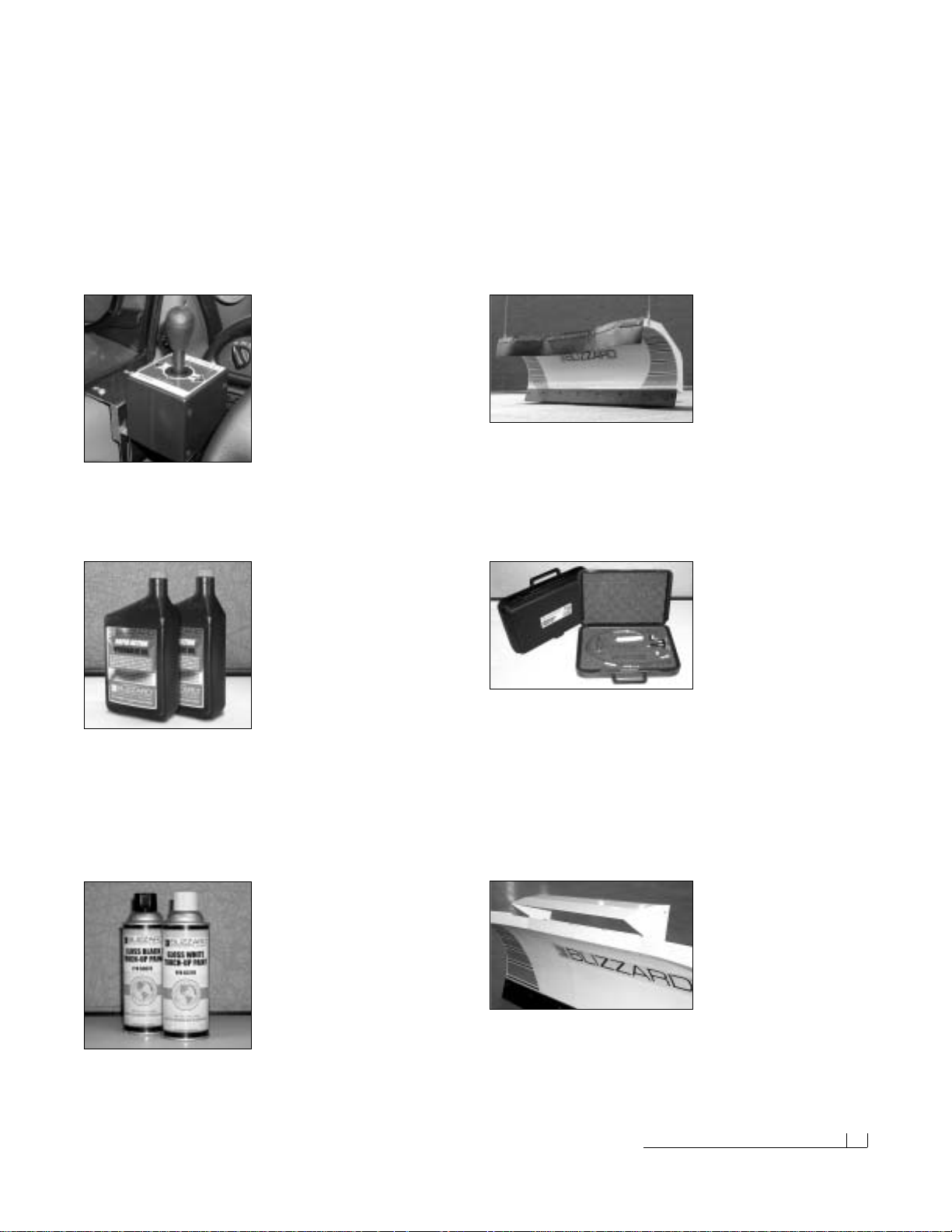
Straight Blade Joystick
Window Mount Bracket
P/N 61261
This adjustable bracket mounts
easily to your straight blade joy-
stick control and installs quickly
onto any door panel. Ideal for left
hand joystick operation or for
vehicles with center consoles.The window mount bracket is shipped
complete with hardware.Some assembly required.
Snowplow Accessories 01
Snowplow Accessories
All of the accessories pictured below are currently offered for your snowplow. See your local Authorized Blizzard Dealer for pricing and availability.
Visit our web site at www.blizzardplows.com to view new snowplow
accessories and our latest Blizzard snowplow wearables.
Rubber Snow Deflector
P/N 81040 (Model 700LD)
P/N 61243 (Model 760LD)
P/N 61242 (Model 760)
P/N 61260 (Model 800)
Plow safer and easier with
our custom rubber snow deflector.This easy-to-install accessory
keeps snow off of your windshield and in its place—on the ground!
Rugged and durable, the 3/8" thick, 2-ply construction is made to last.
All snow deflectors are shipped with complete mounting hardware.
Blizzard Snowplows
Emergency Parts Kit
P/N 63074
Be prepared for unexpected
plow emergencies! This kit
includes the most common
replacement parts conveniently packaged in a small, durable plastic
case.Custom foam insert holds the following plow parts:Angle cylinder hose, lift cylinder hose, hitch pin w/hair pin cotter, angle cylinder
clevis pin w/cotter, 90˚ angle cylinder fitting, solenoid, Power Hitch™
toggle switch, corrosion prev entive compound (2 oz.) and 10A fuse .
The compact case (13.5"x9" x3.3") allows for easy storage behind
or under your truck seat.
Page 4
02 Warning!
Warning!
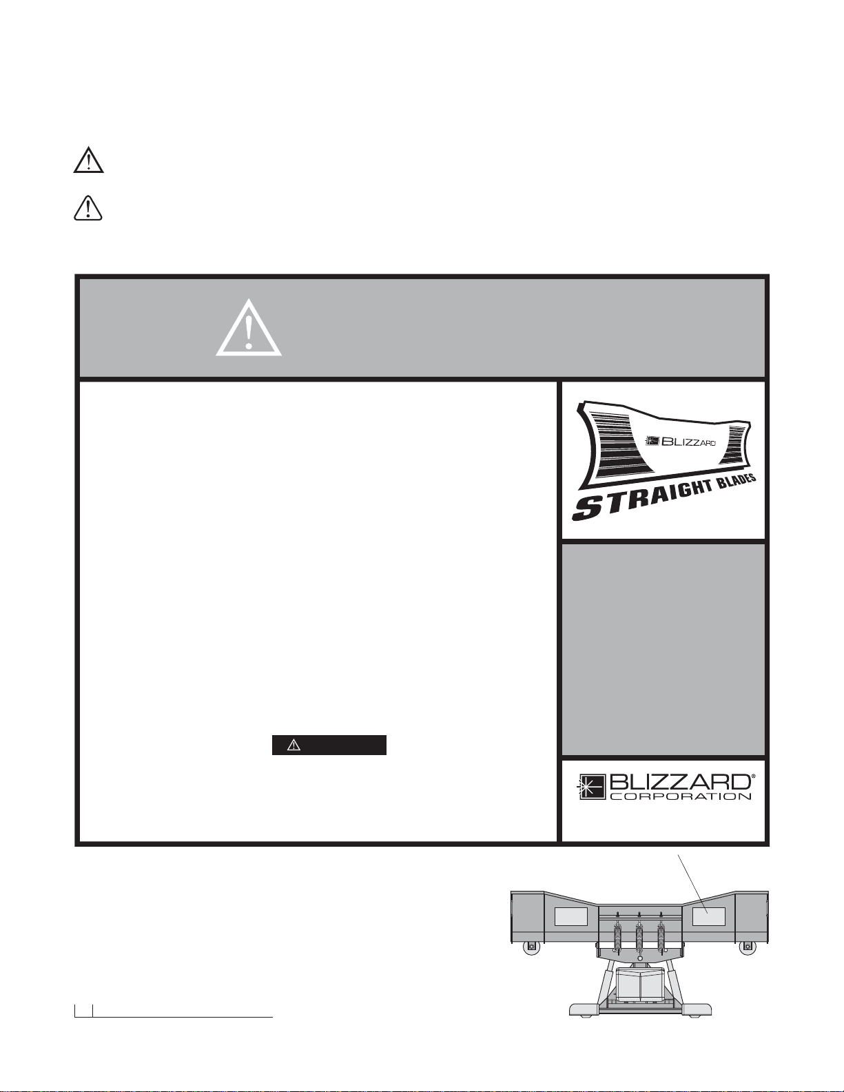
Prior to operating your straight blade, review the WARNING! label at the
passenger’s side rear of the moldboard (shown below).
Note: Read and understand all warnings indicated in this manual prior to
operating the snowplow. Warnings and cautions in the manual are indicated
by the icons shown to the left.
WARNING:
CAUTION:
1. Properly mount the snowplow prior to moving the vehicle.
2. To prevent accidental plow activ ation, turn the Power switch on the snowplow control
to the “OFF” position when not in use.
3. Stand clear of the attachment area when mounting the snowplow to the undercarriage
and operating the Power Hitch Connect/Disconnect switch. Failure to do so may
result in serious injury or death.
4. Securely position all mounting pins prior to operating your snowplow.
5. Do not position your body between the snowplow and the vehicle when servicing
or operating.
6. Position snowplow in such a manner as to not block your vision or plow headlights
while in transit.
7. Do not change the position of the snowplow while in transit.
8. Do not exceed 40 mph when transporting the snowplow.
9. Do not exceed 10 mph when plowing.
10. Always lower the snowplow when the vehicle is parked.
11. Vehicles equipped with air bags are designed to be activated in a frontal collision
equivalent to hitting a solid object or barrier at approximately 14 mph or more.
Careless or high speed driving while plowing snow, which results in vehicle impact
deceleration equivalent to or greater than the airbag deployment threshold described
above, would deploy the airbag.
Blizzard straight blade snowplows are protected by U.S. Patent 6,276,076 B1. Other patents pending.
READ
OWNER’S
MANUAL
THOROUGHLY
PRIOR TO
OPERATING
PLOW.
Calumet, Michigan 49913
BLZ 1024
WARNING
WARNING
Should the WARNING! label or any of the labels
that came with your snowplow become hard to
read or wear off, contact your local Authorized
Blizzard Dealer for replacements.
Page 5
Snowplow Operation 03
Snowplow Operation
Your snowplow is the most advanced and versatile straight blade on the
market.The easy-to-use joystick control allows you to automatically adjust
the plow blade into an infinite number of plowing positions. Review the
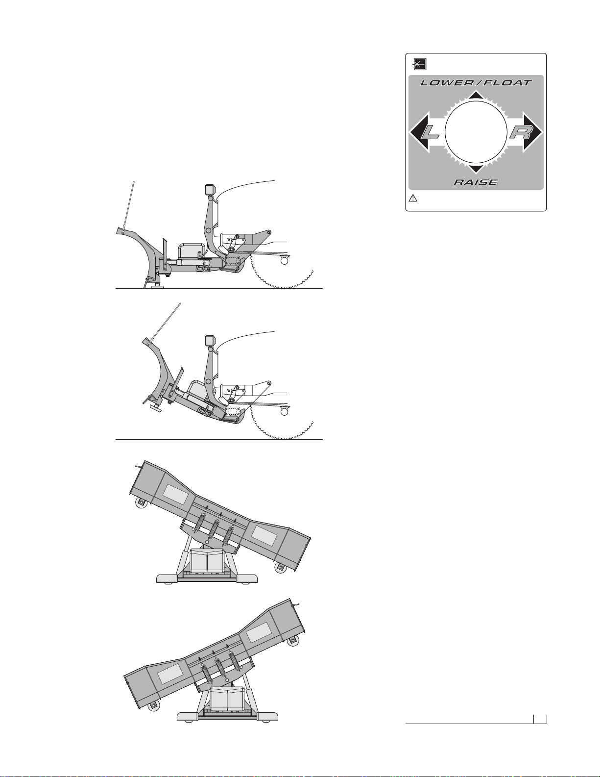
illustrations below for instruction on maneuvering your snowplow.
A.
B.
C.
D.
A. Lowered or Float Position
Pushing the joystick forward, toward the “Lower/
Float” designation on the label, will lower your
straight blade to the ground.Pushing the joystick
ahead until the detent “locks”the control will allow
the snowplow to “float”, or follow the contour of
the ground when moving forward or backward.
B. Raised Position
Pulling the joystick back, toward the “Raise”
designation on the label, will lift your straight
blade off of the ground. To stop raising the plow,
simply return the joystick to its “neutral”or center
position.The snowplow has reached its maximum
raised position when the blade stops lifting –
return the joystick to its neutral position.
C. Angled Right Position
To angle your straight blade to the right, position
the joystick toward the “R” on the label. To stop
angling the plow, return the joystick to its “neutral”
or center position.The snowplow has reached its
maximum angled position when the blade stops
moving to the right side.
D. Angled Left Position
To angle your straight blade to the left, position
the joystick toward the “L” on the label. To stop
angling the plow, return the joystick to its “neutral”
or center position.The snowplow has reached its
maximum angled position when the blade stops
moving to the left side.
***** IMPORTANT *****
To prevent premature failure of the power
contactor (solenoid),initiate the plow function
and return the joystick to its neutral or center
position — except float. DO NOT hold the joystick in any position that allows the pump to
continuously run after the plow has reached
its maximum degree of movement. This will
reduce the useful life of the solenoid.
BLIZZARD
To prevent accidental plow activation, turn
POWER switch to the “OFF” position when
not in use.
BLZ 1017
WARNING
®
Page 6
04 Unpacking & Inspection
Assembly Instructions
Unpacking & Inspection
Your Blizzard straight blade has been packaged to withstand transit and
weather related damage.Fully inspect all components upon receipt of your
plow. In the event of shipping damage or missing parts, immediately contact
our Customer Service Depar tment toll free at 1-888-680-8600.
Begin unpacking and inspection in the following order:
1. Remove the shipping document from the end panel of the pallet wrap.
Retain all documentation for your records.
2. All wood framing and polyethylene material should be removed from
the pallet for easy access to the snowplow.
3. Due to the odd shaped components and size of several assembly
parts, various cable ties and corrugated material are used for scratch
resistance and package orientation. Please remove these items prior
to assembly.
4. Place the main blade assembly on a flat, level surface.
Once you have inspected all parts and removed all packaging materials,
your snowplow is ready to be fully assembled.
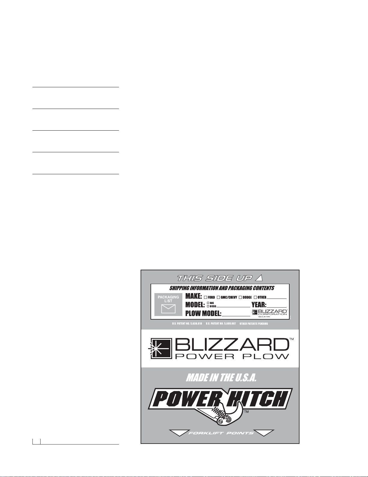
Pallet Wrap End Panel
The tear resistant woven polyethylene pallet wrap
contains a moisture barrier to help protect all
packaged components and keep out the most
inclement weather during shipping and storage.
The end panel of the pallet cover contains important information regarding the snowplow model
and the plow’s serial number.Both of these numbers are given together. The first three digits
and/or two letters in the the number indicated is
always the plow model 700LD , 760LD, 760 or 800
– and the entire seven (nine) digit number make
up the entire serial number.The shipping document is also attached to the end panel.Be sure to
retain this list for your records.
Snowplow Serial Number
Hydraulic Pump Serial Number
Telephone Number
Dealer/Distributor
Date of Purchase
Page 7
Moldboard & A-frame Assembly 05
7/16"
7/16"
45˚ Adjustable Elbow O.R.B.Adapter
9/16"
9/16"
90˚ Adjustable Elbow O.R.B.Adapter
Moldboard & A-Frame Assembly
1. Begin the moldboard assembly by positioning the PIVOT BEAM and
A-FRAME near the connecting points at the rear of the blade between
the two center support ribs. Position the pivot beam between the two
support ribs until the connecting points on the beam align with those
on the plow. Inser t one 3/4"-10 x 3" (2" shank) hex head cap screw
through each mounting hole and secure with a 3/4"-10 top lock nut.
Tighten each nut until it is snug with the pivot beam.
CAUTION:Do not over tighten hex head n uts! Binding may
prohibit the pivot beam from moving properly on the plow.
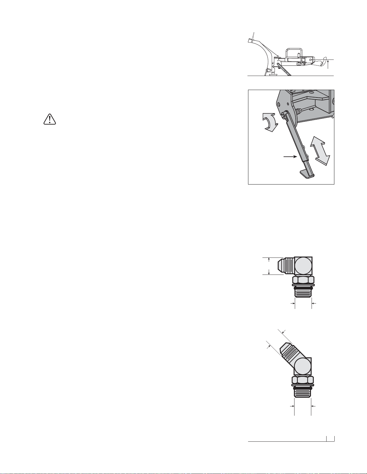
Note:T o aid in the remaining installation, rotate the spring loaded kickstand clockwise until it locks into place.Adjust the foot on the stand
arm so the height of the A-frame, at its mount points, is 12-1/2" to
level ground (See the diagram to the right). Tighten both of the 1/2"-13
top lock nuts on the kickstand.
2. Position each ANGLE CYLINDER with the rod end of the cylinder
in the pivot beam and the hydraulic hose port facing away from the
A-frame.Secure the cylinder to the pivot beam with one 3/4" x 4-1/2"
CLEVIS PIN and one 1/4" x 1-1/2" HAMMERLOCK COTTER PIN.
Note:The hammerlock cotter pin will “lock” itself into place once the
head of the pin is struck. It is not necessary to bend the pin further
upon installation. Extend each cylinder rod until the cylinder base
mounting hole aligns with the hole on the A-frame angle cylinder
bracket. At this point, insert another clevis pin and secure it with a
cotter pin.Repeat the same installation for the opposite angle cylinder.
3. Remove each dust cap from both of the hydraulic angle cylinder ports
and attach one 9/16"-18 x 9/16"-18 90˚ ADJUSTABLE ELBOW O.R.B.
ADAPTER to each port. Note: All of the hydraulic adapters can be
found packaged with the manif old assembly.Reference the table on
page 33 for proper torque specifications. Each adapter should be
angled toward the top of the moldboard.Connect the 3/8" x 24" hydraulic
hose, labeled #1, to the driver’ s side angle cylinder adapter. Attach the
3/8" x 24" hydraulic hose, identified by a #2, to the passenger’s side
angle cylinder adapter.Be careful not to overtighten the hose connections. Route both hoses over the top of each angle cylinder.
4. Next, remove both of the plastic dust caps from the HYDRAULIC
LIFT CYLINDER ports. Attach one 7/16"-20 x 7/16"-20 45˚ ADJUSTABLE ELBOW O.R.B. ADAPTER to the driver’s side port and one
7/16"-20 x 7/16"-20 MALE O.R.B.CONNECTOR ADAPTER to the
passenger’s side port. Once the adapters have been installed on the
cylinder, connect the HYDRAULIC HOSES.Note: Position the fittings
in the cylinder port such that the hoses install directly in the center of
the A-frame access holes.A hose installed too close to the edge of the
opening may work itself free with the operation of the lift cylinder and/
or movement of the plow. The 45˚ adapter on the driver’s side of the
cylinder receives a 1/4" x 17" hose identified by a label containing the
number 3.Connect the 45˚ angle on the hose to the hydr aulic adapter
on the cylinder.The male connector adapter on the passenger’s side
of the cylinder receives a 1/4" x 15" hose identified by a label containing the number 4.Tighten the 45˚ end of the hose to the hydraulic
The kickstand is mounted to the side of the pivot
beam with one 1/2"-13 x 4-1/2" hex cap screw
and top lock nut. To pivot the kickstand, simply
pull the spring loaded leg out and rotate it until
the pin locks into place.The kickstand also has
an adjustable foot that can be moved to accommodate varying vehicle heights. The proper
height of your snowplow mounting points to level
ground should be set at 12-1/2".
Spring Loaded
Adjustable
Pivot Beam
Kickstand
12-1/2"
Page 8
06 Moldboard & A-frame Assembly (cont.)
adapter on the cylinder.Both hoses should be routed through the triangular openings in the A-frame.
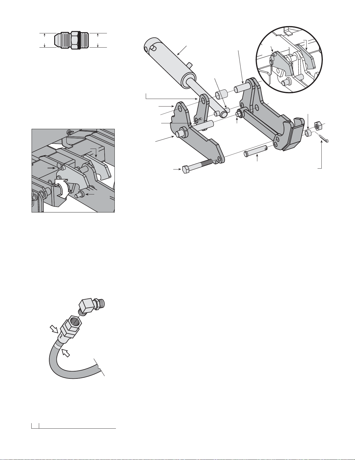
5. Begin the draw latch installation by first removing the DRAW LATCH
MOUNT PIN & SPACER from the assembly. By removing this pin, the
INNER DRAW LATCH PLATES can swing free.Proceed to remove
the INNER DRAW LATCH PLATE LIFT CYLINDER MOUNT PIN.
Position the plates on either side of the lift/lo w er cylinder rod and insert
the pin through the plates and cylinder rod.With the cylinder connected
to the inner draw latch plates, rotate the draw latch assembly toward
the draw latch mount holes on the A-frame.Align the holes in the outer
draw latch plate with those of the inner draw latch plates and the
A-frame. Note: The A-FRAME LATCH, located at the rear center of
the A-frame, should be raised up to insert the draw latch mount pin.
Pull the A-FRAME LATCH PULL PIN out and rotate the latch counterclockwise if it is locked into position.Secure the assembly to the A-frame
by replacing the draw latch mount pin and spacer.Reset the A-frame
latch so the A-frame latch pull pin locks into place.
Once you have completed the draw latch installation, we will shift our
attention to assembly of the manifold.The manifold, pump and coil harness
have been joined together at the factory; however, the manifold contains
several components that you will need to install prior to securing the
assembly to the A-frame.
6. Each of the 4 HOSE PORTS on the HYDRAULIC MANIFOLD are
covered with stretch wrap .Remove the wrap and install the appropriate
fitting (illustrated on page7) in its respective port.
Note: All por ts are identified by a stamped number on the manifold.
The numbers also identify the hydraulic functions, which can be referenced on the label under the hydraulic pump and manifold cover
(see illustration on page 7).
7/16" 7/16"
Male O.R.B.Connector Adapter
A-Frame
Latch Pull Pin
A-Frame
Latch
Outer Draw
Latch Plate
Inner Draw
Latch Plate
Draw Latch Mount Pin
(1" DIA. x 4-21/32") or
(1" DIA. x 3-7/8") for
700LD & 760LD only
Inner Draw Latch
Plate Lift Cylinder
Mount Pin
(3/4" DIA. x 2-1/2") or
(5/8" DIA. x 2-3/8") for
700LD & 760LD only
Draw Latch Arm
Pivot Pin
(3/4" DIA. x 2-1/2") or
(3/4" DIA. x 2-3/8") for
700LD & 760LD only
Hydraulic
Lift / Lower
Cylinder
Draw Pin
(1" DIA. x 6-1/2") or
(1" DIA. x 5-5/8") for
700LD & 760LD only
3/16" x 2-1/2"
Cotter Pin
Hex Head Cap Screw
(3/4"-10 x 4-1/2") or
(3/4"-10 x 4") for
700LD & 760LD only
1" O.D., 25/32" I.D. x 5/8"
Spacer
Clevis Pin
(3/4" x 3-41/64") or
(3/4" x 3-7/16") for
700LD & 760LD only
1/4" x 1-1/2"
Hammerlock
Cotter Pin
Draw Latch Assembly
The draw latch consists of a series of interconnected plates and pins that attach to the A-frame
and the hydraulic lift cylinder.
Draw
Pin
A-Frame
Latch
Lock Pin
A-Frame
Latch
To mount the straight blade, the A-frame latch
should be lowered over the draw pin– this allows
the draw latch to pull the plow into the undercarriage. Once the plow is safely attached to the
undercarriage, rotate the A-frame latch counterclockwise until the lock pin snaps into place.The
A-frame latch is only used to mount the plow.
Do not allow the lock pin to set behind the pin
catch hole in the raised position.The A-frame
latch should always be locked in place when
not in use.
Stamped
Number
Printed
Label
All of the hoses shipped with the snowplows
contain either a stamped number on the sleeve or
a printed label applied to the hose. All numbers,
stamped or printed, correspond with the stamping
of the ports on the manifold.
Page 9
Moldboard & A-frame Assembly (cont.) 07
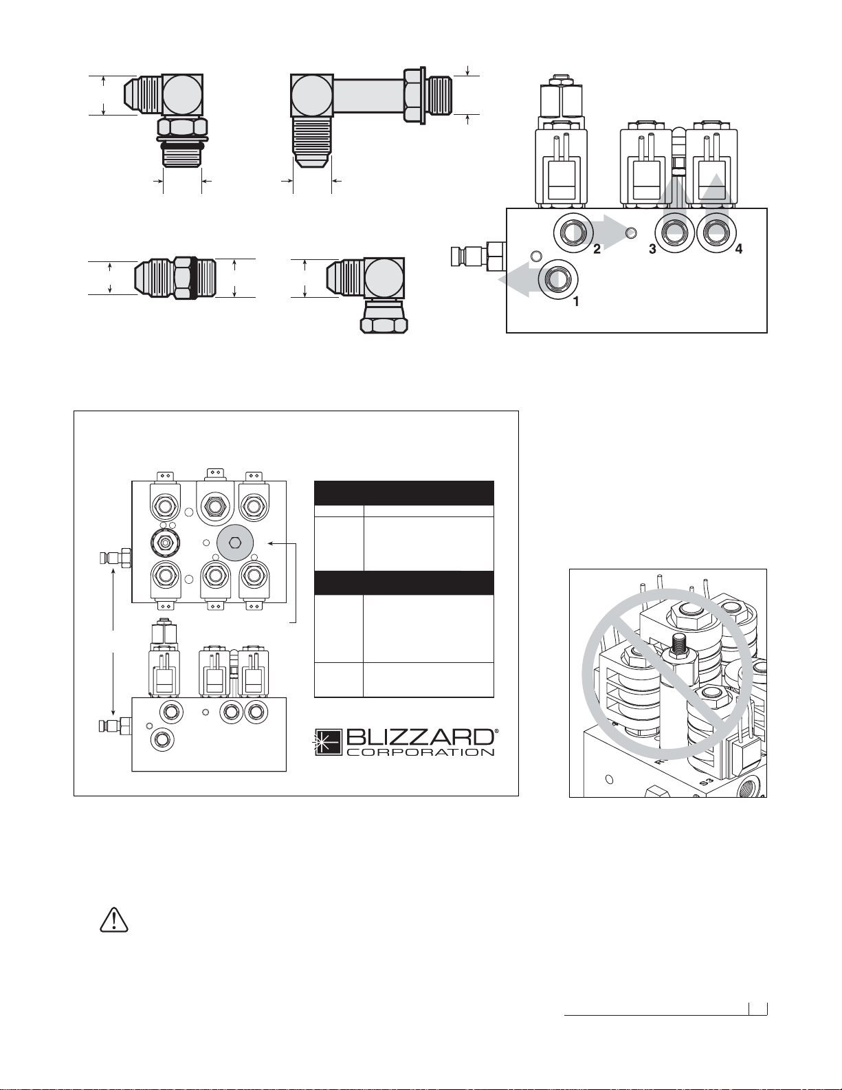
Installing The Manifold Adapters
There are a total of 6 hydraulic adapters to install.
All of the adapters can be found packaged with
the manifold assembly. Remove the protective
stretch wrap from the manifold in a clean area.
DO NOT let any foreign objects enter into the
open ports.The valves can become contaminated
and greatly hinder the plow’s performance.
Review the table on page 33 for proper torque
specifications.
7/16" 9/16"
7/16"
9/16"
9/16"
9/16"
9/16"
Male O.R.B.Connector Adapter & 90˚ Swivel Elbow Adapter
(Ports #3 & #4)
90˚ Adjustable Elbow O.R.B.Adapter
(Port #1)
Male Extra Long Elbow Adapter
(Port #2)
S6 S8S4
RV FC
S3 S5 S7
Hydraulic Hose Identification Guide
Straight Blade Snowplows
Calumet, Michigan 49913
HYDRAULIC HOSES
1
23 4
Port Function
S3 Left Angle - Right Cylinder
S4 Right Angle - Left Cylinder
S6 & S7 Raise - Lift Cylinder (Base)
S5 & S8 Lower - Lift Cylinder (Rod)
S5 & S7 Float
RV Angle Relief Valve
FC Variable Flow Control Valve
BLZ 1035
NOTE: Energize the following
solenoids for the functions:
1Right Angle - Left Cylinder
2 Left Angle - Right Cylinder
3Raise - Lift Cylinder (Base)
4Lower - Lift Cylinder (Rod)
Pressure Gauge
Quick Connect
Clockwise - Decreases Plow Drop Speed
Counterclockwise - Increases Plow Drop Speed
Note: The gray arrows shown on the manifold illustration above indicate
the direction the 90˚ adapters should face to receive the hydraulic hoses.
7. Next, align the mount holes in the pump with the holes in the hinged
bracket, located on the A-frame .Note:To help facilitate the pump mount,
first angle the hinged bracket as needed and tighten the bracket
hardware, locking it in place.
CAUTION:When installing the manifold between the mount
brackets on the A-frame, hold the manifold at the sides of
the block.Never handle the manifold b y the wire lead coils.
Doing so can cause a solenoid cartridge to bend, causing
the cartridge to stick when activated.
When installing the manifold between the mount
brackets on the A-frame, DONOT handle the
manifold by the wire lead coils.The solenoid
cartridges can bend, causing them to stick when
activated.Always carry the manifold by the sides
of the aluminum block.
Page 10
08 Moldboard & A-frame Assembly (cont.)
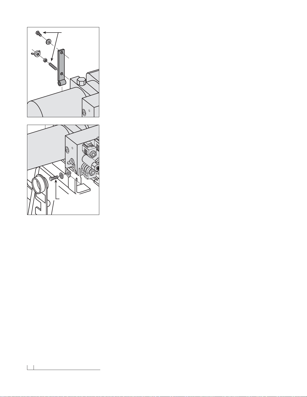
Secure one 3/8"-16 x 3/4" hex head cap screw and 3/8" flat washer
through the top mount hole in the bracket and into the pump. Insert
one 3/8"-16 x 1-3/4" threaded stud and 3/8"-16 jam nylon insert lock
nut through the bottom mount hole in the bracket and into the pump.
The threaded stud should bottom out in the pump.Note:A medium
strength threadlocker , such as Loctite®242® should be used on both
of the pump mount fasteners.This will help prev ent the fasteners from
working free.
8. Once the pump and manifold assembly is in place, connect the
hydraulic hoses to their respectiv e adapters on the manifold. Remember,
the labeling on the hydraulic hoses correspond with the stamped
numbers on the manifold.
Begin installing the hoses with the driver’s side r aise cylinder hose (#3).
Attach the straight end of the hose to the 7/16"-20 x 9/16"-18 90˚
swivel elbow adapter on the manifold. Connect the passenger’s side
lower cylinder hose to Port #4. Loop the hose through the opening in
the A-frame and connect the straight end of the hose to the 7/16"-20
90˚ swivel elbow adapter. Run both angle cylinder hoses (#1 and #2)
over the A-frame angle and to their respective manifold por ts. Note:
The lift cylinder hoses should be routed through the triangular openings
in the A-frame.
9. Next, secure the manifold to the A-fr ame.Remove both 3/8" flat washers,
3/8" split lock washers and 3/8"-16 x 1" hex head cap scre ws from the
manifold and align the mount holes with the A-frame brac kets .Position
the DIODE PACK MOUNT BRACKET against the outside of the Aframe bracket on the driv er’s side. Note: Both of the prongs should be
facing up.Align the outside hole on the diode bracket with the holes
on the A-frame and manifold.Properly replace and tighten all hardware.
Note:A medium strength threadlocker, such as Loctite®242® should
be used to secure the manifold mount fasteners.
10. Hook each EXTENSION SPRING to the receiving holes located on
the pivot beam and connect the opposite end of the spring to their
respective SPADE BOLTS.Install the 5/8"-11 x 5" spade bolts through
the EXTENSION SPRING MOUNTING ANGLE on the top rear of the
blade.Secure each spade bolt by placing one 5/8" flat washer on the
bolt and thread one 5/8"-11 nylon insert lock nut.Tighten each lock nut
until a piece of paper can pass between the 3th & 4th coils on the spring.
11. Install the flexible BLADE GUIDES at each end of the moldboard.
Insert the 5/16"-18 x 1" hex head cap screw through the holes provided
at the top of the outside reinforcement rib.Tighten all screws using the
nylon insert lock nuts provided.
Congratulations! You have successfully completed half of the installation.
Don’t quit now, you’re nearly out of the garage!
A medium strength threadlocker, such as Loctite®
242®, should be used to properly secure the
mount hardware for the pump and manifold. This
will help prevent the hardware from working free
from vibration and plow use. Apply a liberal
amount of threadlocker to both threaded fasteners and the threads in the pump (top diagram).
The manifold receives two 3/8"-16 x 1" hex cap
screws—one on each side of the A-frame. Likewise, use threadlocker on these fasteners and
the tapped holes in the manifold (bottom diagram).
Use Loctite® on
Manifold Mount
Hardware
Apply Loctite®
To Pump Mount
Hardware Upon
Installation
Page 11
Electrical Assembly - Plow Harness 09
Electrical Assembly - Plow Harness
1. Begin the electrical assembly by connecting the RED POWER WIRE
from the PLOW ELECTRICAL HARNESS to the PUMP motor terminal
stud using the hardware provided on the pump.
2. Place one 3/8" INTERNAL/EXTERNAL TOOTH LOCK WASHER, the
BLACK GROUND WIRE (from the harness) and the RED GROUND
WIRE on the COIL WIRE HARNESS (from the manifold) over the
tapped hole on the pump and secure the ground using one 3/8"-16 x
3/4" hex head cap screw.
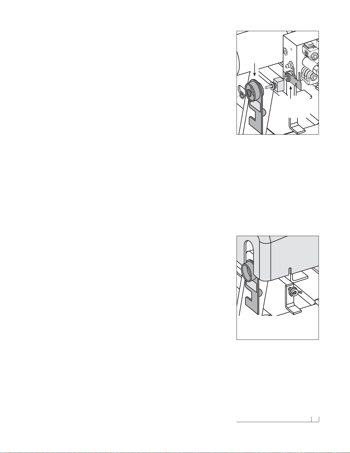
3. Remove the hex jam nut and external tooth lock washer from the
POWER HITCH CONNECT/DISCONNECT TOGGLE SWITCH and
insert it through the back of the mounting bracket on the A-frame.Align
the notch in the key washer on the switch to the notch on the bracket.
Replace the lock washer and jam nut and tighten until the switch is
firmly in place. Next, attach the connector on the plow harness to the
switch. Note: Use caution when making the connection.Switches can
break if done forcefully.
4. Continue the harness installation by connecting the PLASTIC FEMALE
ELECTRICAL CONNECTOR on the harness to the PLASTIC MALE
ELECTRICAL CONNECTOR found on the coil wire har ness.
5. Finalize the harness installation by sliding the DIODE PACK over the
diode pack mount brack et located behind the connect/disconnect toggle
switch. Position the wire har ness braid in the notch on the switch
bracket and secure it with a cable tie.The diode pack mount bracket
contains an extra hole f or a cable tie. Use it to secure the diode pack.
6. To install the PUMP & MANIFOLD COVER, align the notches in the
cover with the welded bolts on the A-frame br ack ets.Secure the cover
with two 3/8" FLANGED WING NUTS. Verify the cover is positioned
over the protective toggle switch hood.Pop the front of the cover on
the threaded stud and secure it with the remaining wing nut.
Congratulations! You have just completed building the finest snowplow
available! However, the vehicle wire harness still needs to be installed.
That is the focus of the second half of the electrical assembly instruction.
Diode Pack
Mount Bracket
Draw Latch
Toggle Switch
Mount Bracket
The diode pack (on the plow harness) clips onto
the diode pack mount bracket.Place a cable tie
through the hole at the end of the bracket and
over the pack to secure it in place.
The draw latch toggle switch installs through the
rear of the bracket with the protective hood.Align
the key washer with the slot cut in the bracket to
prevent the switch from turning. Secure the
switch with the hardware provided.Note: Use the
square notch in the bracket (below the protective
hood) to position the braided harness.Use another
cable tie to hold the harness against the bracket.
The Pump Cover Installs Over
The Top Of The Draw Latch
Switch Bracket
To properly secure the pump and manifold cover
on the A-frame, position the cover over the top of
the protective hood on the draw latch switch
mount bracket. Align the slots in the cover with
the welded bolts on the A-frame brackets—
secure the cover using three flanged wing nuts.
Page 12
10 Electrical Assembly - Vehicle Harness
Electrical Assembly - Vehicle Harness
CAUTION:Alwa ys perf orm the vehic le wire harness assembly with the vehicle off and the keys out of the ignition. Use
caution when testing the electrical wires for the vehicle’s
headlight functions.
1. Begin the installation of the electrical har ness under the hood. Insert
the WHITE POWER CONNECTOR & RED POWER WIRE (with FUSE)
end of the harness through the driver’s side fire wall access panel into
the vehicle cab.Note:You may need to widen an opening or cut access
to the cab interior to facilitate the assembly. Loosely position the
remaining portion of the harness over the driver’s side fender w ell and
place the MOLDED RUBBER POWER CONNECTOR near the bumper .
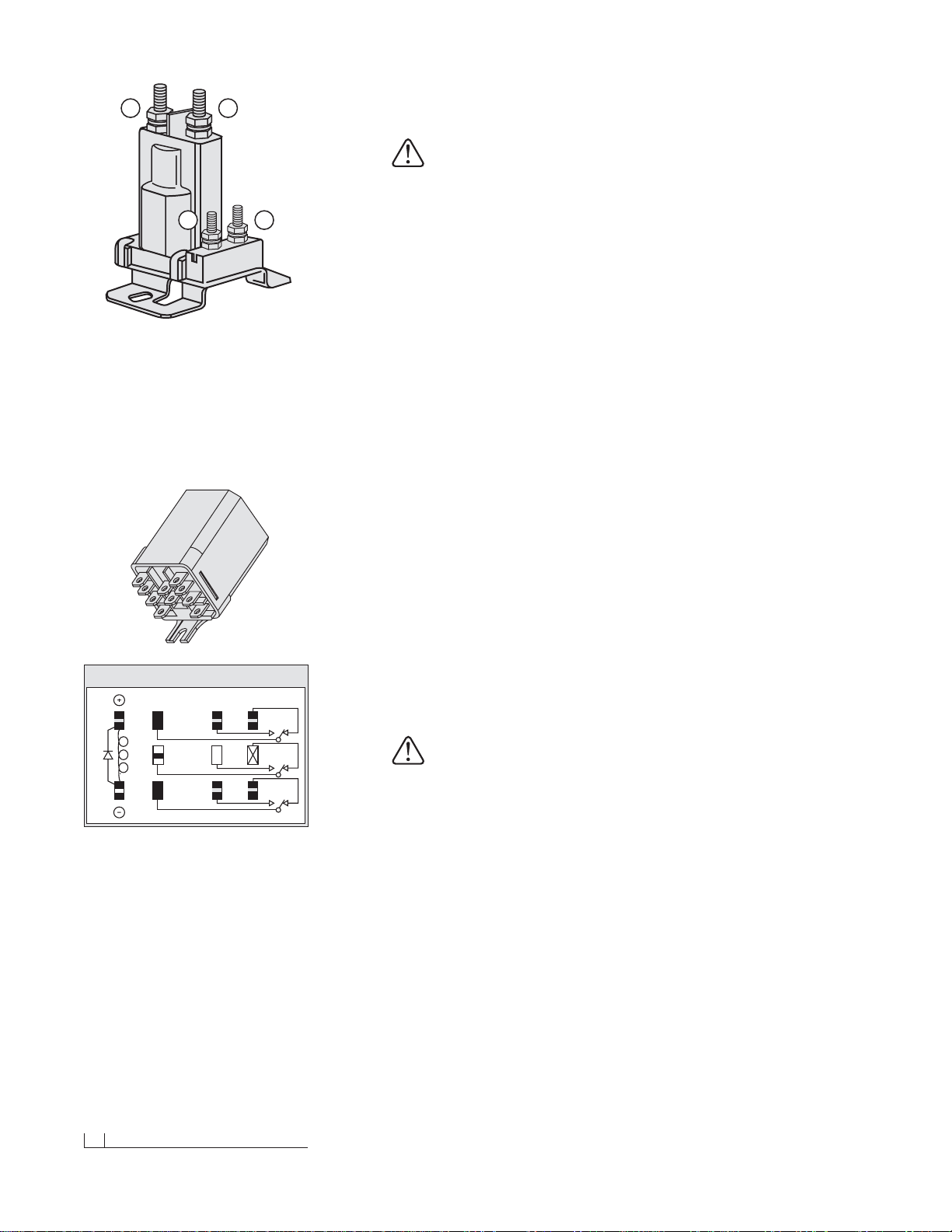
2. Next, attach the POWER CONTACTOR (SOLENOID) to the driver’s
side wheel well or engine fan guard using two 12-14 x 3/4" hex washer
self-drilling screws.Note: Some model vehicles provide mounting
locations for accessory components.Connect the 24" BLACK GROUND
WIRE to either small terminal on the solenoid and attach the opposite
end to the vehicle with one hex washer self-dr illing screw. Locate the
BROWN/WHITE PUMP SOLENOID ACTIVATION WIRE on the wire
harness and position the eyelet over the remaining small terminal on
the contactor.Secure it with the hardware provided on the solenoid.
3. Proceed to connect the BLACK VEHICLE WIRE HARNESS GROUND
WIRE to the negative terminal on the vehicle’ s battery.Cut the wire to
length and crimp a 3/8" DIA. END RING TERMINAL on the wire.It is
also recommended that the ring terminal be soldered. Note: The har-
ness should be secured to the vehicle prior to taking the necessary
measurement. Measure the distance needed for the RED POWER
WIRE to reach the solenoid and properly secure an end ring terminal
to it. Connect the power wire to either large terminal on the solenoid.
CAUTION:Do not fasten the wire harness to areas that come
in contact with moving engine parts or possess extreme
heat.The harness could become tangled and/or melt causing
electrical failure and vehicle damage.
4. Attach and solder an end ring ter minal to both ends of the remaining
length of the red 4 gauge wire. Connect one end of the wire to the
open terminal on the solenoid and the remaining end to the positive
terminal on the battery.
5. With the vehicle harness secured to the truck, position the MAIN
LIGHTING HARNESS such that both of the large, gray VEHICLE
HEADLIGHT CONNECTORS are near the truck headlights and the
smaller, black PLOW HEADLIGHT CONNECTORS are near the grill
of the vehicle.
6. Plug the 9 TERMINALS, from the main lighting har ness, into the
HEADLIGHT RELAY. See the illustration to the left. Connect the
GREEN & YELLOW wire, from the vehicle harness with the molded
power plug, to the remaining spade on the relay. Securely mount the
relay to the vehicle with the terminals facing down. Installing the relay
in this position will allow moisture to drain from the relay.
A B
C D
Heavy-Duty Power Contactor (Solenoid)
There are four wires that need to be attached to
the power contactor:
(A) Red Power Battery Wire
(B) Vehicle Wire Harness Red Power Wire
(C) 24" Black Ground Wire
(D) Brown/White Pump Solenoid Activation Wire
A
B
G/Y
BK/W
Y7
W/R 8
LT. G 9
HIGH
GROUND
LOW
Y/B 4
WHITE 5
Y/R 1
N/A 2
LT. G/B 6
LT. G/R
3
3PDT RELAY (30 AMPS) 12 VOLTS
Connect the color coded wires from the vehicle
harness to the headlight relay shown above.The
wires correspond to the numbers/letters on the
relay or the color abbreviations on the illustration.
(A) BK/W = Black/White Wire
(B) G/Y= Green/Yellow Wire
(1) Y/R = Yellow/Red Wire
(2) N/A = Not Applicable
(3) LT.G/R = Light Green/Red Wire
(4) Y/B = Yellow/Black
(5) W = White
(6) LT.G/B = Light Green/Black
(7) Y = Yellow
(8) W/R = White/Red Wire
(9) LT. G= Light Green
Page 13
Elec. Assem. - Vehicle Harness (Cont.) 11
7. Next, remove the front directional light assembly on the driver’s side
of the vehicle.Feed the VIOLET, turn light wire and GRAY, run light wire
from the main lighting harness through the opening in the directional
light housing. At this point, use a test light or ohm meter to determine
the proper wires in the vehicle’s electr ical system to splice into. Once
you have identified the proper wires, position one end of the turn or
run light wire into a SPLICE LOCK CONNECTOR provided. Attach
the vehicle wire to the opposite side of the splice lock connector.
Complete the splice by pinching both wires together and locking the
connector.Repeat the splice procedure for the remaining wire. The
passenger’s side directional light assembly requires the same installation;howev er, only one wire, the PINK, turn light, needs to be spliced.
8. Connect the vehicle headlights to the main lighting harness using a
HEADLIGHT ADAPTER KIT. Due to differences in the construction
of the adapter kits, and the various make and model v ehicles Blizzard
snowplows are installed on (see list to the right), a headlight adapter
kit is not packaged with your snowplow. Contact your local Blizzard
Dealer to obtain the appropriate adapter for your vehicle.
9. Begin the adapter kit installation by removing the existing vehicle headlight connector from the headlight. Attach the HEADLIGHT ADAPTER
CONNECTOR to the existing vehicle headlight connector. Next, plug
the BLACK, FIVE-PIN CONNECTOR on the headlight adapter into
the gray, five-pin connector on the vehicle wire harness.Lastly, plug the
HEADLIGHT ADAPTER CONNECTOR into the vehicle headlight receptacle. Note: If more than one plug is present, match the colors of
each connector (ie gray to gr ay, black to black, Chevrolet da ylight running is clear to gray). Repeat the installation for the opposite headlight.
10. Once the headlight adapter connections are completed, proceed to
secure the braided harness to the vehicle. Safely route all harness
lengths around the engine components and attach them to the vehicle
with cable ties.Extend the PLOW HEADLIGHT CONNECTORS, from
the main lighting harness, through the grill of the vehicle and position
the HARNESS POWER PLUG and WEATHER CAP near the bumper.
Cable tie the power plug to the vehicle bumper or tow hook to keep
the harness from hanging too low.
11. Return to the driver’s side cab interior to install the remainder of the
vehicle wire harness.Find an accessible location f or the PLOW HEADLIGHT TOGGLESWITCH & BRACKET under the dashboard. Install
the headlight bracket using two self-drilling screws. Inser t the toggle
switch through the bracket and secure it with the hardware provided.
Use the MALE 2-PIN POWER CONNECTOR to connect the toggle
switch to the vehicle wire harness.
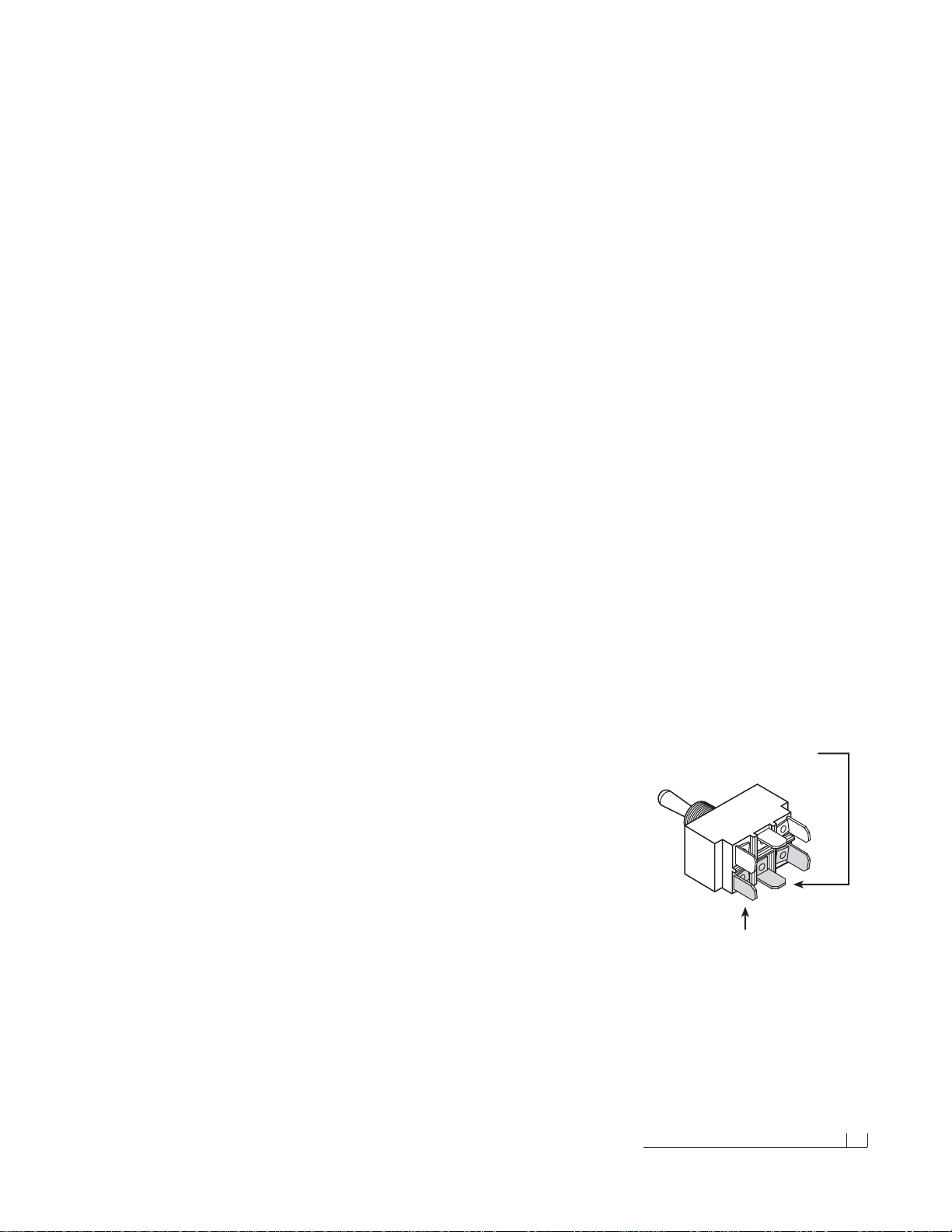
First, insert the 24" GREEN/YELLOW GROUND LEAD into the
FEMALE 2-PIN POWER CONNECTOR (on the vehicle wire harness).
This lead should be grounded to the vehicle.Next, plug both of the
SWITCH LEADS into the toggle switch.Note: Both terminals should
be inserted into the spades on the same side of the switch. One
terminal should be positioned in the middle spade. See the illustration
to the right and on page 32. Plug both 2-pin power connectors together.
Vehicle Headlight Adapter Kits
P/N Vehicle Application
62010 1980 & Older, 1983-1993 Dodge
1995-1996 Chevrolet/GMC & Ford
62011 1987-1992 Ford, 1991 & Newer Dodge
3/4 & 1 Ton
62012 1993 & Newer Ford, 2002 & Newer
Dodge 1/2 Ton
62013 1990-1999 GMC, 1991-1999 Chevrolet
(Except ’99 Chevrolet Silverado & ’99 GMCSierra)
62014 1999 & Newer Chevrolet Silverado &
GMC Sierra (with Daytime Running Lights)
62015 1989 Chevrolet
62050 2000-2001 Dodge 1/2 Ton
62051 1980 & Older Chevrolet/GMC & Dodge
Note: Additional vehicles are continually being
added to accommodate Blizzard snowplow models.
Contact your local Blizzard Dealer for specific
vehicle application information.
Insert one terminal into
the middle spade.
Remaining terminal connects
to either spade on the SAME
side of the switch.
Page 14
12 Testing The Snowplow
12. Connect the RED POWER WIRE (with 10 AMP FUSE) to a switched
power source with a minimum of 10 amps.Note:The red power wire
MUST be fused and switched on and off with ignition.Secure all loose
wires under the dash.
13. Next, install the LIGHT TOWER. Position the tower arms into the
receiving pockets located on the undercarriage push beam.Align the
mounting holes in the light tower with those on the push beam and
insert two 1/2"-13 x 1-1/4" hex head cap screws. Secure the screws
with 1/2" washers and top lock nuts.See your local Blizzard Dealer
for complete installation instructions for your vehicle undercarriage.
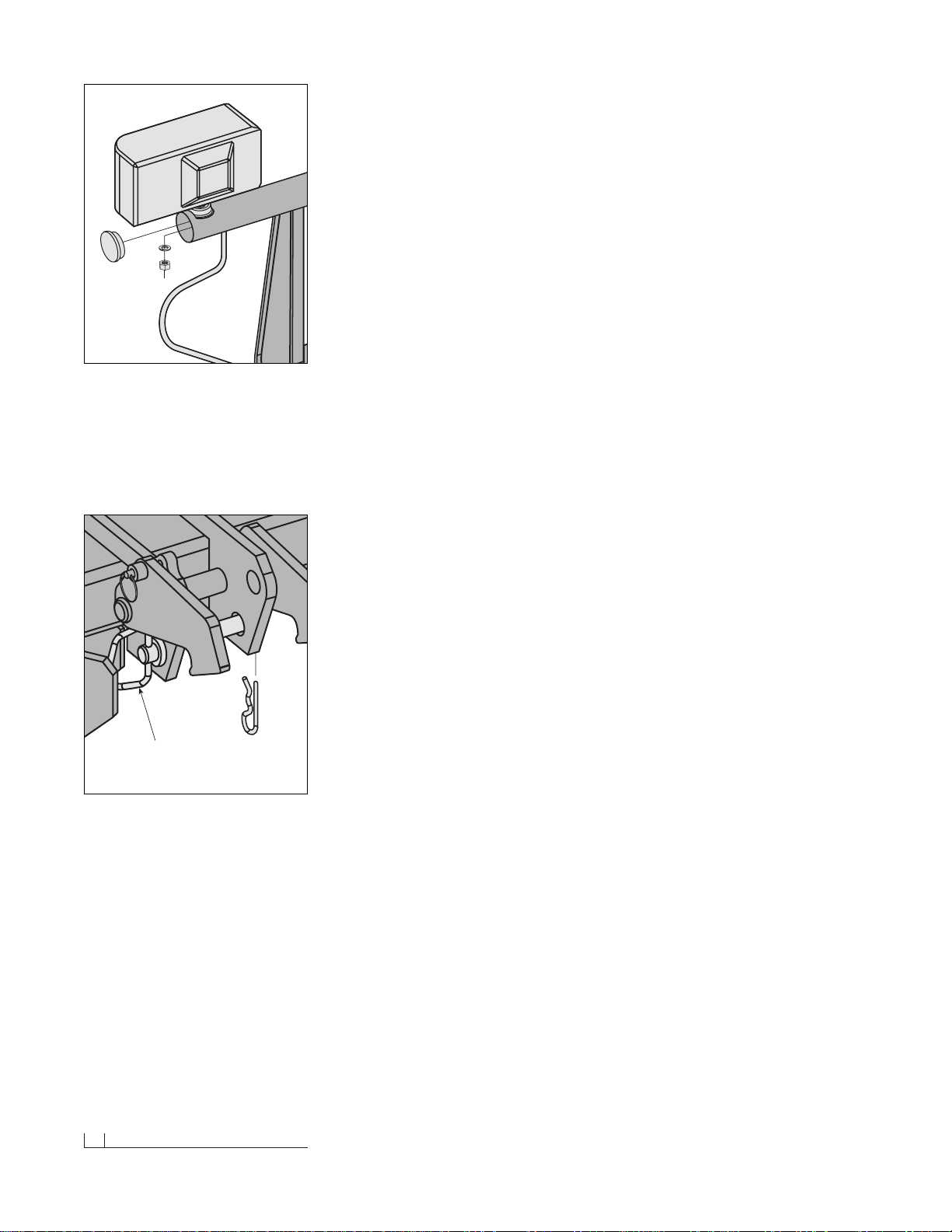
14. Proceed to install the PLOW HEADLIGHTS. Align one HEADLIGHT
BALL STUD MOUNT ADAPTER on the light tower tube with the
mounting hole and insert the threaded stud through each. Secure the
headlight with one 1/2" split lock washer and hex nut. Note: All snow-
plows are shipped with two BLACK DOME PLUGS that install at
either end of the light tower. For secure placement, apply a bead of
silicone around the perimeter of the plug prior to installation on the
light tower .Connect the terminals from the plow lights to the terminals
on the main lighting harness. Repeat the installation for the opposite
headlight.
15. Align the four mount holes on the JOYSTICK CONTROL with the
holes located on the JOYSTICK BENCH MOUNT PEDESTAL.Note:
The radius on the pedestal should face the dashboard. Secure the
joystick to the pedestal with f our 8-32 x 3/4" machine scre ws pro vided.
Next, slide the VELCRO® STRAP through the slots cut in the pedestal.
The metal D-RING should be located on the side opposite of the radius.
Wrap the strap around the bench and fasten.Finally, connect the
white power connector from the vehicle wire harness to the connector
on the control station.The power switch on the joystick should be in
the “OFF” position.
This completes the electrical assembly installation for the vehicle wire
harness and main lighting harness.You are now ready to perform all of
the test functions on the snowplow.
Testing The Snowplow
1. Fill the HYDRAULIC PUMP FLUID RESERVOIR with BLIZZARD
SNOWPLOW RAPID ACTION HYDRAULIC OIL (P/N 63070) until it
is approximately 3/4" from the top of the tank.Replace the cap on the
reservoir.Proceed to remove the weather caps from each of the plow
and vehicle wire harnesses and connect the plugs.Tur n the POWER
SWITCH on the joystick in the cab to the “ON” position and turn the
vehicle ignition switch on.Y ou no w ha v e power to the sno wplo w. Once
all of the hydraulic functions have been executed, the system will have
been filled with approximately 3 to 3-1/2 quarts of hydraulic oil.
Dome
Plug
Apply a thin bead of silicone around the inside
perimeter of the polyethylene dome plugs prior to
capping the light tower ends. The silicone will
help retain the dome plug inside of the headlight
mount tube.
Emergency Hitch Pin
& Hair Pin Cotter
In the event you should lose hydraulic power while
snowplowing, raise the snowplow into a pile of
snow and insert the emergency hitch pin.The pin
will lock the plow in a temporary raised position
until proper service can be performed to restore
hydraulic power. Note: For clarity, the draw latch
is not shown in this illustration.
Page 15
Testing The Snowplow (Cont.) 13
2. Raise the DRAW LATCH on the snowplow by pushing and holding the
toggle switch on the A-frame upward into the “CONNECT” position.
Notice the action of the fluid in the reservoir.By activating the initial
hydraulic function, the fluid begins to fill the system.Push and hold the
toggle switch in the “DISCONNECT”position, the draw latch will lower.
Refill the reservoir until the fluid is 3/4" from the top of the tank.
3. Position the vehicle such that the draw latch is below the push beam
and the mounting points on the A-frame are in line with the mounting
points on the undercarriage. Pull out the A-FRAME LATCH PIN and
rotate the A-FRAME LATCH clockwise until the latch is resting on the
DRAW PIN (See diagr am on page 14).Move the snowplow in position
by activating the draw latch connect switch and release.
WARNING: Always use caution when operating the draw
latch CONNECT/DISCONNECT switch. Keep your hands and
feet away from the operation of the draw latch and the main
blade.The action of the draw latch moves the snowplow in
position for proper attachment to the vehic le.Failure to follo w
this warning may result in serious injury or death.
The draw latch will raise until it hits the push beam and the DRAW
LATCH FINGERS will pull the plow into the vehicle.The mounting
points on the plow and vehicle are now positively aligned. Rotate the
A-frame latch counterclockwise until the latch is locked in the raised
position. Note: The A-frame latch pin should always lock in place. Do
not set the pin past the lock point on the A-frame. Insert the two
HITCH PINS through the mounting holes on the A-frame and secure
each with one hair pin cotter.The snowplow is now securely mounted
to the vehicle.
4. Return to the inter ior of the vehicle.With the plow securely in place,
you can now execute the remaining functions of the snowplow.The
power supply on the joystick should be in the “ON” position. Next, raise
the plow to its maximum height by pulling back (“RAISE”) on the joystick.Angle the snowplow to the left b y mo ving the joystick toward the
“L” (left angle) on the label. If the plow function is slow or delayed, the
hydraulic fluid is filling the cylinder and replacing the air in the system.
Continue testing the remaining joystick functions .Monitor the fluid level
in the reservoir and fill to 3/4" from the top of the tank if needed. Also,
look for any h ydraulic fluid leaks around the manif old, pump , h ydraulic
hoses and all cylinders.
5. Lastly, check that the vehicle and plow headlights are in proper working condition including the turn signals. If necessar y, adjust the plow
headlight beams with the plow in the raised position.
Congratulations on a successful assembly and installation! Once all of the
blade and electrical functions have been tested your Blizzard straight
blade is ready for action. Should you need additional support during a
plow assembly or undercarriage installation, contact your local A uthorized
Blizzard Dealer.
BLIZZARD
To prevent accidental plow activation, turn
POWER switch to the “OFF” position when
not in use.
BLZ 1017
WARNING
®
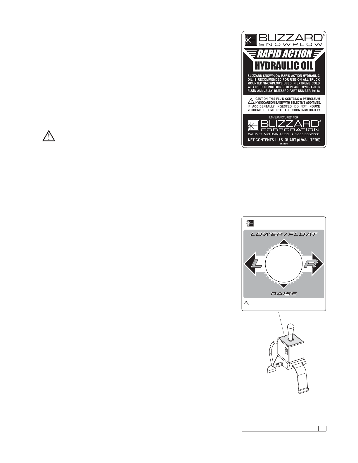
Your Blizzard Straight Blade snowplow will use
approximately 3 to 3-1/2 quarts of Blizzard Rapid
Action Hydraulic Oil.Note:The part number issued
on the quart bottle label has been changed to
P/N 63070.Blizzard hydraulic oil is also available
by the case (P/N 63071).See your local Authorized
Blizzard Dealer for price and availability.
Page 16
14 Mounting & Dismounting Instructions
Mounting & Dismounting
Instructions
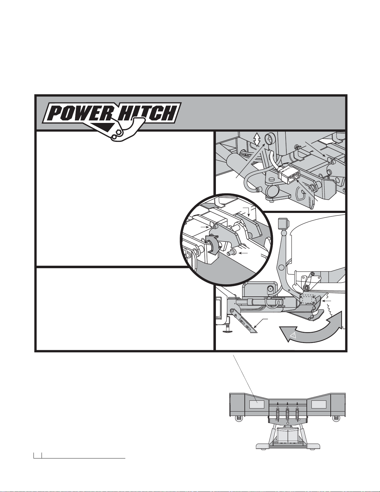
Prior to operating your straight blade, review the Mounting & Dismounting
Instructions label at the driver’s side rear of the moldboard (shown below).
MOUNTING & DISMOUNTING
INSTRUCTIONS
Power Hitch Raises & Lowers
Behind Undercarriage Push Beam
MOUNTING
1. Position vehicle close to the plow and align mounting points on the undercarriage and
A-frame. Verify that the plow kickstand is in the lowered position. Turn vehicle ignition off.
2. Turn power supply switch on the main plow control unit in the vehicle to the “OFF” position.
3. Remove protective weather caps and make electrical connection at the plow and vehicle.
4. Turn the vehicle ignition, and the power supply switch on the control unit, to the “ON”
position. Pull the A-frame latch lock pin outward and verify that the A-frame latch lowers
over the draw pin.
5. Activate the Power Hitch on the A-frame by pushing and holding the “CONNECT/
DISCONNECT” switch (on the pump cov er housing) upw ard. CAUTION: Keep
fingers away from plow and truck mounting points. Power Hitch will
automatically pull the plow into the receiving points on the truck
when activated. Insert both hitch pins through the positively aligned holes
on the plow and undercarriage and secure each with a hair pin cotter.
6. With the plow securely mounted, slightly lower the Power Hitch to relie ve
tension on the A-frame latch, pull the latch lock pin and raise the A-frame
latch until it locks into position. Raise the Power Hitch and verify that the
draw latch is fully engaged behind the push beam on the vehicle. Rotate
the kickstand counterclockwise until it locks into place. The plow is now
properly mounted and ready to operate.
DISMOUNTING
1. Lower the plow on a flat, level surface to dismount. Turn vehicle ignition off.
2. Pull the kickstand lock pin outward and rotate the kickstand clockwise. Release the pin
to lock kickstand in place. Remove both hitch pins from the A-frame and undercarriage.
3. Tu rn the vehicle ignition and the power supply switch on the control unit to the “ON”
position. Activate the Power Hitch by pushing and holding the “CONNECT/DISCONNECT”
switch downward. CAUTION: Keep fingers away from plow and truck mounting points.
Verify that the draw latch is fully disengaged from behind the push beam on the vehicle.
4. Turn power supply switch on the main plow control unit in the vehicle to the “OFF” position.
5. Disconnect electr ical cords at the plow and vehicle. Replace protective weather caps.
Adjustable
Kickstand
Draw
Latch
K
E
E
P
F
I
N
G
E
R
S
A
W
A
Y
!
BLZ 1023
A-Frame Latch
Lock Pin
Plug To Vehic le
Wire Harness
CONNECT /
DISCONNECT
Toggle Switch
A-Frame Latch
Rotates Clockwise
And Hooks Onto
Draw Pin
Draw
Pin
A-Frame
Latch
Lock Pin
A-Frame
Latch
TM
Should the Mounting & Dismounting Instructions
label or any of the labels that came with your
snowplow become hard to read or wear off, contact
your local Authorized Blizzard Dealer for
replacements.
Page 17
Regular Maintenance 15
Regular Maintenance
Your Blizzard straight blade snowplow has been designed for years of
rugged, dependable service with low maintenance. To ensure proper
working condition, follow the maintenance guidelines below and on the
next page.
CAUTION: Always follow the maintenance guidelines in a timely
fashion. Failure to observe maintenance guidelines may result
in poor snowplow operation, increased component wear or
possibly lead to part failure.
Routinely inspect the following items – perfor m maintenance as needed:
1. All fasteners, pins, nuts and bolts for tightness. See the recommended
maximum bolt torque chart on page 33.
2. All hydraulic hoses and hydraulic hose adapters for wear and leaks.
See the recommended hydraulic adapter torque values on page 33.
3. All cylinders for leaks;inspect rod ends for corrosion and pitting.
4. Cutting edges and plow shoes for wear.Do not discard plow shoe
washers.These should be retained for different shoe adjustments.
5. Clean and lubricate all electrical plugs, headlight connections, ground
and battery cables, solenoid connections and switch connections to
prevent corrosion.Apply dielectric grease for every 25 hours of snowplow use.You may need to grease more frequently depending on your
plowing environment.
6. Lubricate all pins and bushings to prevent corrosion and to maintain
consistent operation. A NLGI Grade 2 multipurpose lithium complex
grease with molybdenum (MPGM) is recommended for lubrication.
7. Clean and cover deep scr atches or e xposed metal with Blizzard Snowplow white (P/N 61219) or black (P/N 63073) touch-up paint.Contact
your local Blizzard Dealer for availability.
8. Check the hydraulic oil level in the hydraulic pump fluid reservoir. Fill
the fluid to within 3/4" from the top of the reservoir.Do not exceed this
level.Never mix different types of fluids. Contact your local dealer for
replacement Blizzard Snowplow Rapid Action Hydraulic Oil (P/N 63070).
9. Check the trip spring adjustment. Properly adjusted tension will allow
a sheet of paper to pass between the 3rd and 4th coils of the spring.
10.To adjust the snowplow drop speed, use the variable flow control valve
(FC) on the manifold (see label under pump & manifold cover).Turn the
dial on the valve clockwise to decrease the drop speed. Tur n the dial
counterclockwise to increase the drop speed.See the Troubleshooting
Guide on page 35 for additional instructions.
11.Do not allow snow and ice to build-up on the pump and manif old co v er.
Excessive build-up ma y cause bumper damage when the plow is r aised.
Maintenance Schedule
Maintenance Performed Date
Page 18
16 Storing Your Snowplow
Storing Your Snowplow
Placing Your Plow In Storage
1. Position your plo w on a flat, level surface for storage.Follow the dismounting procedure illustrated on page 14.
2. Pressure wash and dry the entire snowplow prior to placing in storage.
3. Apply a liberal amount of dielectric grease to all electrical plugs and
connections. Clean and install all dust caps.
4. Lubricate all exposed hydraulic cylinder rod ends with liquid white
lithium grease to prevent corrosion.
5. Lubricate all pins and bushings to prevent corrosion and to maintain
consistent operation. A NLGI Grade 2 multipurpose lithium complex
grease with molybdenum (MPGM) is recommended for lubrication.
6. Clean and cover deep scr atches or e xposed metal with Blizzard Snowplow white (P/N 61219) or black (P/N 63073) touch-up paint.Contact
your local Blizzard Dealer for availability.
7. Remove and properly discard the fluid from the pump reservoir.Clean
the pump filter and replace the hydraulic oil to within 3/4" from the top
of the reservoir.Changing the fluid annually will prolong the life of your
pump and manifold.Never mix different types of hydraulic oil. Contact
your local dealer for replacement Blizzard Snowplow Rapid Action
Hydraulic Oil (P/N 63070).
8. Cover the snowplow with a tarp if stored outside.This will protect your
plow from sun fading and inclement weather which can lead to
accelerated corrosion.
Removing Your Plow From Storage
1. Perform all regular maintenance indicated on the previous page.
2. If you have not replaced the hydraulic oil in the pump reser voir, it is
strongly encouraged that you do so prior to operating your plow. Prolonged storage could result in condensation build-up.
3. Follow the mounting procedure illustrated on page 14.
4. Once the plow has been properly mounted to the vehicle and all
electrical connections have been made, initiate all of the functions of
the snowplow .Monitor the fluid level in the reservoir and fill to 3/4" from
the top of the tank if needed.
5. Adjust the snowplow headlights as needed.
Annual Fluid Replacement
Type & Quantity of Fluid Replaced Date
Page 19

Plow Specifications 17
Plow Specifications
Moldboard
Length
700LD ..................................................................................7'-0"
760LD ..................................................................................7'-6"
760 ......................................................................................7'-6"
800 ......................................................................................8'-0"
Thickness........................................................................12 Gauge
Height
700LD..............................................................................26-1/2"
760LD....................................................................................28"
760 & 800 ..............................................................................29"
Reinforcement
700LD & 760LD ..................................................4 Ribs @ 3/16"
760 & 800 ............................................................6 Ribs @ 1/4"
Cutting Edge
700LD & 760LD ................................................3/8" x 6" (1080)
760 & 800 ..........................................................1/2" x 6" (1080)
Finish ............................................................Powder Coat - White
Trip Mechanism
Trip Spring Type
700LD ..............................................(2) 3/8" Hooked Extension
760LD ..............................................(3) 3/8" Hooked Extension
760 & 800 ........................................(4) 3/8" Hooked Extension
Trip Spring Adjustment
All Models............................................5/8"-11 x 5" Spade Bolts
A-frame
Material ................................................Rec. Tube & Channel Type
Hitch Pins ................................................3/4" x 4-3/4" Yellow Zinc
Emergency Hitch Pin ..................................1" x 5-3/4" Yellow Zinc
Finish..............................................................Powder Coat - Black
Pump
Construction............................Steel Housing w/Clear Plastic Tank
Type ................................................................Internal Gear Pump
Motor ............................................................................12V Starter
Volume Per Minute ....................................1.25 GPM @ 1500 PSI
Weight....................................................................................32 lb.
Mount ....................................A-frame Install w/Hex Head Screws
Reservoir Capacity ............................................................2 quarts
Controls ..................................................Toggle Switch & Joystick
Manifold
Construction ............................................Red Anodized Aluminum
Ports..............................................................................................4
Cartridge Valves............................................................................6
Relief Valv e ..................................................................................1
Flow Control Valve ........................................................................1
Weight ................................................................................13.8 lb.
Mount ....................................A-frame Install w/Hex Head Screws
Maximum Flow Capacity ......................................................2 gpm
Angle Cylinders
Stroke
700LD & 760LD ................................................................9-3/8"
760 & 800 ..............................................................................10"
Ram Diameter
All Models ..........................................................................1-3/4"
Bore Diameter
All Models ................................................................................2"
Lower/Raise Cylinder
Stroke
700LD & 760LD ................................................................4-1/4"
760 & 800 ..........................................................................4-5/8"
Ram Diameter
700LD & 760LD........................................................................1"
760 & 800 ..........................................................................1-1/4"
Bore Diameter
700LD & 760LD ................................................................1-3/4"
760 & 800 ..........................................................................2-1/2"
Plow Headlights
Type ......................................................Low Profile w/Turn Signals
Measurements ......................................10-3/4" W x 5"H x 5-3/2"D
Housing ..............................................................Plastic Composite
Mount..............................................................Adjustable Ball Type
Bulb Type ..................High/Low Sealed Beam Halogen, 12V Rect.
Switch Type ....................................................Dash Mount, Toggle
Miscellaneous
Plow Weight*
700LD..................................................................Approx. 528 lb.
760LD..................................................................Approx. 550 lb.
760 ......................................................................Approx. 720 lb.
800 ......................................................................Approx. 750 lb.
Adjustable Plow Shoes
700LD & 760LD ......................................................(2) Standard
760 & 800 ..........................................(2) Heavy-Duty Cast Steel
Mount Mechanism ........................................Hydraulic Draw Latch
Control Station....................................................................Joystick
*Plow weight does not include vehicle undercarriage.
Unless otherwise indicated, all specifications are for Models 700LD, 760LD, 760 & 800
straight blade snowplows.
Blizzard Corporation reserves the right, under its Continuous Improvement Policy, to change
construction or design details and furnish equipment when so altered without reference to
illustrations or specifications.
Page 20
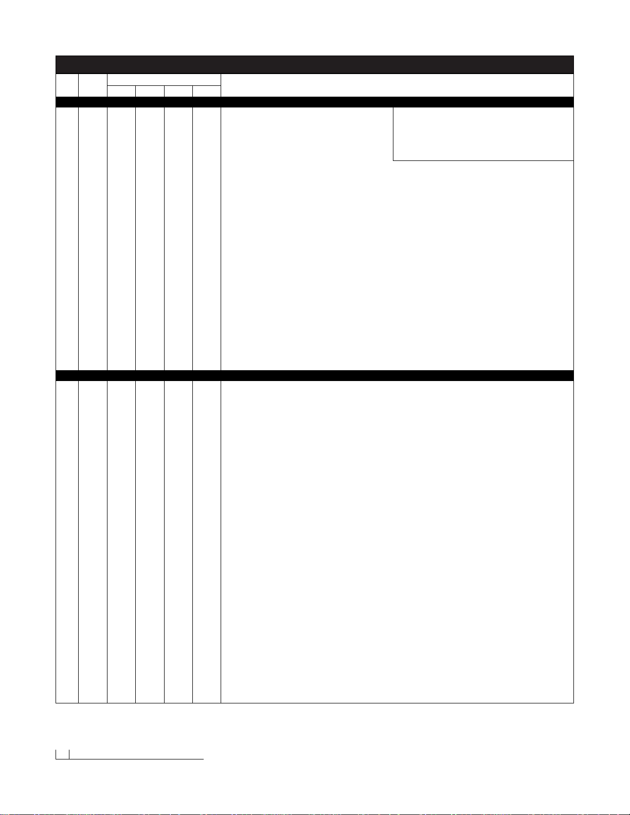
Ref. Part Build Quantity Part Description
No. No.
1 81021 1 N/A N/A N/A Moldboard Weldment - Model 700LD
81006 N/A 1 N/A N/A Moldboard Weldment - Model 760LD
84006 N/A N/A 1 N/A Moldboard Weldment - Model 760
80006 N/A N/A N/A 1 Moldboard Weldment - Model 800
2 81031 1 N/A N/A N/A Cutting Edge, Moldboard (1080) - Model 700LD
61165 N/A 1 N/A N/A Cutting Edge, Moldboard (1080) - Model 760LD
61168 N/A N/A 1 N/A Cutting Edge, Moldboard (1080) - Model 760
61164 N/A N/A N/A 1 Cutting Edge, Moldboard (1080) - Model 800
3 61196 6 8 8 8 Carriage Bolt, 1/2"-13 x 1-1/2" P
4 61026 10 12 12 12 Washer, SAE Mil-Carb High-Strength, 1/2", 1-1/16" O.D., 17/32" I.D.YZ
5 61020 11 13 13 13 Nut, Top Lock, 1/2"-13 Grade C Z
6A 61098 2 2 N/A N/A Plow Shoe Assembly, Standard (7-3/4" Shaft) - Models 700LD & 760LD: (1) - 6 & 8, (18) - 7
61220 N/A N/A 2 2 Plow Shoe Assembly,Heavy-Duty Cast Iron (8-3/8" Shaft) - Models 760 & 800: (1) - 6 & 8, (18) - 7
6 61102 2 2 2 2 Spacer, 1-5/8" O.D, 1-1/8" I.D. x 1-1/2" YZ
7 61101 36 36 36 36 Washer, Flat, 1", 1-3/4" O.D., 1-1/16" I.D.Z
8 61103 2 2 2 2 Pin, Linch, 1/2" x 1-3/4"
9A 61049 2 2 2 2 Plow Guide Assembly: (2) - 9 & 10
9 61051 4 4 4 4 Screw, Hex Head Cap, 5/16"-18 x 1" Grade 5 Z
10 61052 4 4 4 4 Nut, Nylon Insert Lock, 5/16"-18 Z
11 63066 1 N/A N/A N/A Decal, Passenger’s Side Moldboard (BLZ 1050) - Model 700LD
61176 N/A 1 1 N/A Decal, Passenger’s Side Moldboard (BLZ 1019) - Models 760LD & 760
61178 N/A N/A N/A 1 Decal, Passenger’s Side Moldboard (BLZ 1021) - Model 800
12 61181 1 1 1 1 Label, WARNING! (BLZ 1024)
13 61175 1 1 1 1 Decal, Center Moldboard (BLZ 1018)
14 61180 1 1 1 1 Label, Power Hitch™ Mounting & Dismounting Instructions (BLZ 1023)
15 63067 1 N/A N/A N/A Decal, Driver’s Side Moldboard (BLZ 1051) - Model 700LD
61177 N/A 1 1 N/A Decal, Driver’s Side Moldboard (BLZ 1020) - Model 760LD & 760
61179 N/A N/A N/A 1 Decal, Driver’s Side Moldboard (BLZ 1022) - Model 800
16 63062 1 N/A N/A N/A Label, Sequential Serial Number (BLZ 1048) - Model 700LD
61199 N/A 1 N/A N/A Label, Sequential Serial Number (BLZ 1029) - Model 760LD
61183 N/A N/A 1 N/A Label, Sequential Serial Number (BLZ 1026) - Model 760
61184 N/A N/A N/A 1 Label, Sequential Serial Number (BLZ 1027) - Model 800
17 61188 2 3 4 4 Nut, Nylon Inser t Lock, 5/8"-11 Type NE
18 61064 2 3 4 4 Washer, SAE Mil-Carb High-Strength, 5/8", 1-5/16" O.D., 21/32" I.D. YZ
19 61201 2 3 4 4 Bolt, Spade, 5/8"-11 x 5" Grade 8 Z
20 61351 2 N/A N/A N/A Spring, Extension, 10-3/4" O.A.L. x 2-3/8" O.D., 3/8" Wire Diameter - Model 700LD
61167 N/A 3 N/A N/A Spring, Extension, 12-15/16" O.A.L. x 2-3/8" O.D.x 3/8" Wire Diameter - Model 760LD
61099 N/A N/A 4 4 Spring, Extension, 15-1/4" O.A.L. x 2-3/8" O.D. x 3/8" - Models 760 & 800
21 61006 3 3 4 4 Nut,Top Lock, 3/4"-10 Grade C Z - Models 760 & 800
22 61063 1 1 N/A N/A Nut,Top Lock, 5/8"-11 Grade C Z - Models 700LD & 760LD
23 61314 2 2 2 2 Screw, Hex Head Cap, 3/4"-10 x 3" (with 2" Shank) Grade 8 YZ
24A 41039 1 1 1 1 Kickstand Assembly: (1) - 24-26, 28, 29, (2) - 4, 27, (3) - 5
24 61152 1 1 1 1 Screw, Hex Head Cap, 1/2"-13 x 4-1/2" Grade 8 YZ
25 41038 1 1 1 1 Kickstand Leg Weldment
26 41047 1 1 1 1 Kickstand Foot Weldment
27 61057 4 4 4 4 Screw, Hex Head Cap, 1/2"-13 x 1-1/4" Grade 8 YZ
28 61293 1 1 1 1 Spring, Compression, 2" O.A.L. x 1.101" O.D., 0.207 Wire Diameter
29 41037 1 1 1 1 Bushing, Stepped, 1.13" O.D., 0.53" I.D. x 3/8" Stainless Steel
30 83000 1 1 N/A N/A Pivot Beam Weldment - Models 700LD & 760LD
41041 N/A N/A 1 1 Pivot Beam Weldment - Models 760 & 800
31 41050 4 4 4 4 Pin, Clevis, 3/4" DIA. x 4-1/2" YZ
32 61357 5 5 5 5 Pin, Hammerlock Cotter, 1/4" x 1-1/2"
33 61331 1 1 N/A N/A Screw, Hex Head Cap, 1"-8 x 8-1/2" (with 7-1/8" Shank) Grade 8 P - Model 700LD & 760LD
61330 N/A N/A 1 1 Screw, Hex Head Cap, 1"-8 x 9" (with 7-3/4" Shank) Grade 8 P - Models 760 & 800
34 61008 1 1 1 1 Nut, Top Lock, 1"-8 Grade C Z
35 60065 2 2 N/A N/A Hydraulic Cylinder, Plow Angle - Models 700LD & 760LD
60029 N/A N/A 2 2 Hydraulic Cylinder, Plow Angle - Models 760 & 800
36 60005 3 3 3 3 Hydraulic Adapter, 9/16"-18 x 9/16"-18 90˚ Adjustable Elbow O.R.B.
37 60091 1 1 1 1 Hydraulic Hose (#1), 3/8" x 24" - Plow Angle, Driver’s Side
38 60011 1 1 1 1 Hydraulic Hose (#2), 3/8" x 24" - Plow Angle, Passenger’s Side
39 61253 1 1 N/A N/A Screw, Hex Head Cap, 5/8"-11 x 5-1/2" Grade 8 YZ - Models 700LD & 760LD
61005 N/A N/A 1 1 Screw, Hex Head Cap, 3/4"-10 x 6" Grade 8 YZ - Models 760 & 800
40 60092 1 1 1 1 Hydraulic Hose (#3), Straight/45˚, 1/4" x 17" - Plow Raise/Lower, Extend (Base End)
41 60002 1 1 1 1 Hydraulic Adapter, 7/16"-20 x 7/16"-20 45˚ Adjustable Elbow O.R.B.
42 60118 1 1 N/A N/A Hydraulic Cylinder, Plow Raise/Lower - Models 700LD & 760LD
60130 N/A N/A 1 1 Hydraulic Cylinder, Plow Raise/Lower - Models 760 & 800
43 60004 1 1 1 1 Hydraulic Adapter, 7/16"-20 x 7/16"-20 Male O.R.B.Connector
44 60093 1 1 1 1 Hydraulic Hose (#4), Straight/45˚, 1/4" x 15" - Plow Raise/Lower, Retract (Rod End)
45 61358 3 3 3 3 Nut, Flanged Wing, 3/8"-16
46 61012 2 2 2 2 Screw, Hex Head Cap, 3/8"-16 x 3/4" Grade 8 YZ
47 61016 3 3 3 3 Washer, SAE Mil-Carb High-Strength, 3/8", 13/16" O.D., 13/32" I.D., YZ
MODELS 700LD, 760LD, 760 & 800 PARTS LIST
18 Pa rts List (1 of 4)
700LD 760LD 760 800
Note: The reference numbers listed identify parts shown
in the illustrations on pages 22-24. These numbers are
specific to these illustrations only and do not correspond
with other diagrams in the manual.Always review the part
number given for proper component identification.
Moldboard Assembly Parts
Pivot Beam & A-frame Assembly Parts
Page 21
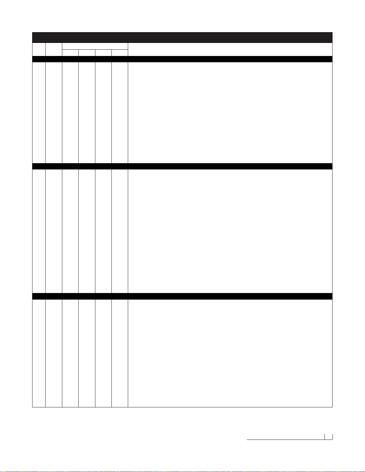
MODELS 700LD, 760LD, 760 & 800 PARTS LIST
Ref. Part Build Quantity Part Description
No. No.
48 61014 1 1 1 1 Nut, Jam Nylon Insert Lock, 3/8"-16 Z, Type NTE
49 61359 1 1 1 1 Stud, Threaded, 3/8"-16 x 1-3/4"
50 40004 1 1 1 1 Hinge Weldment, Pump Mount
51 61218 1 1 1 1 Screw, Hex Head Cap, 3/8"-16 x 2" Grade 8 YZ
52 61034 1 1 1 1 Nut, Top Lock, 3/8"-16 Grade C Z
53 62038 1 1 1 1 Switch, Toggle, DPDT, (On)-Off-(On), 16 Amps, 115V AC - Draw Latch Connect/Disconnect
54A 82048 1 1 N/A N/A A-frame Assembly - Models 700LD & 760LD: (1) - 50-52, 54, 57-59, 65, (2) - 64, (4) - 62, 63
40105 N/A N/A 1 1 A-frame Assembly - Models 760 & 800: (1) - 50-52, 54, 57-59, 65, (2) - 64, (4) - 62, 63
54 82043 1 1 N/A N/A A-frame Weldment - Models 700LD & 760LD
40091 N/A N/A 1 1 A-frame Weldment - Models 760 & 800
55 61115 2 2 2 2 Pin, Hitch, 3/4" x 4-3/4" YZ
56 61105 2 2 2 2 Pin, Hair Cotter, 9/64" DIA. x 2-11/16" Z
57 40079 1 1 1 1 Pin, A-frame Latch, 3/8" DIA. x 1-3/4", Stainless Steel
58 61000 1 1 1 1 Spring, Compression, 0.94" O.A.F.L. x 0.36" O.D., 0.029" Wire Diameter, Stainless Steel
59 61309 1 1 1 1 Ring, Standard Split, 1.48" O.D., 1.264" I.D., 0.92 Wire Diameter
60 61197 1 1 1 1 Pin, Emergency Hitch, 1" x 5-3/4" YZ
61 61226 1 1 1 1 Pin, Hair Cotter, 11/64" DIA. x 3-3/4" Z
62 61312 4 4 4 4 Screw, Hex Head Cap, 5/16"-18 x 3/4" Grade 8 YZ
63 61011 6 6 6 6 Washer, Split Lock, 5/16" YZ High-Alloy
64 40088 2 2 2 2 Bushing, A-frame Pivot, Replaceable
65 61295 1 1 1 1 Label, Power Hitch Connect/Disconnect Switch (BLZ 1037)
66A 82049 1 1 N/A N/A Draw Latch Assembly - Models 700LD & 760LD: (1) - 21, 32, 66-70, 72-79, (2) - 71
40109 N/A N/A 1 1 Draw Latch Assembly - Models 760 & 800: (1) - 21, 32, 66-70, 72-74, 77-79, (2) - 71, 75
66 82035 1 1 N/A N/A Outer Draw Latch Plate Weldment, Driver’s Side - Models 700LD & 760LD
40080 N/A N/A 1 1 Outer Draw Latch Plate Weldment, Driver’s Side - Models 760 & 800
67 82050 1 1 N/A N/A Pin, Draw, 1" DIA.x 5-5/8" (with 13/64" DIA. Cotter Pin Hole) BZ
40110 N/A N/A 1 1 Pin, Draw, 1" DIA.x 6-1/2" (with 13/64" DIA. Cotter Pin Hole) YZ
68 61363 1 1 1 1 Pin, Cotter, 3/16" x 2-1/2"
69 61200 1 1 N/A N/A Screw, Hex Head Cap, 3/4"-10 x 4" Grade 8 YZ- Models 700LD & 760LD
61004 N/A N/A 1 1 Screw, Hex Head Cap, 3/4"-10 x 4-1/2" Grade 8 YZ - Models 760 & 800
70 82055 1 1 N/A N/A Pin, Clevis, 3/4" DIA.x 3-7/16" BZ
50071 N/A N/A 1 1 Pin, Clevis, 3/4" DIA. x 3-41/64" YZ
71 82014 2 2 N/A N/A Inner Draw Latch Plate - Models 700LD & 760LD
40074 N/A N/A 2 2 Inner Draw Latch Plate - Models 760 & 800
72 82027 1 1 N/A N/A Pin, Draw Latch Mount (To A-frame), 1" x 3-7/8" BZ - Models 700LD & 760LD
40070 N/A N/A 1 1 Pin, Draw Latch Mount (To A-frame), 1" x 4-21/32" YZ - Models 760 & 800
73 82054 1 1 N/A N/A Draw Latch Arm Weldment - Models 700LD &760LD
40114 N/A N/A 1 1 Draw Latch Arm Weldment - Models 760 & 800
74 82037 1 1 N/A N/A Draw Latch Finger Weldment - Models 700LD &760LD
40082 N/A N/A 1 1 Draw Latch Finger Weldment - Models 760 & 800
75 82033 1 1 N/A N/A Pin, 5/8" x 2-3/8" BZ, Inner Draw Latch Plate/Hydraulic Cylinder Rod End, Plow Raise/Lower - Models 700LD & 760LD
40042 N/A N/A 2 2 Pin, 3/4" x 2-1/2", Draw Latch Arm Pivot Pin/Hydraulic Cylinder Rod End, Plow Raise/Lower - Models 760 & 800
76 82024 1 1 N/A N/A Pin, 3/4" x 2-3/8" Draw Latch Arm Pivot - Models 700LD & 760LD
77 40093 1 1 1 1 Bushing, 1-1/4" O.D., 1-1/16" I.D. x 1-1/2" YZ
78 82036 1 1 N/A N/A Outer Draw Latch Plate Weldment, Passenger’s Side - Models 700LD & 760LD
40081 N/A N/A 1 1 Outer Draw Latch Plate Weldment, Passenger’s Side - Models 760 & 800
79 40116 1 1 1 1 Spacer, 1" O.D., 25/32" I.D. x 5/8" YZ
80A 60101 1 1 1 1 Hydraulic Pump Assembly (Fenner Fluid Power): (1) - 80-83
80 60045 1 1 1 1 Reservoir, Hydraulic Pump
81 60046 1 1 1 1 Reservoir Cap, Hydraulic Pump
82 60044 1 1 1 1 Hex Cap, Relief Valve, Hydraulic Pump
83 60047 1 1 1 1 Power Unit (Motor), Hydraulic Pump
84 61307 1 1 1 1 Washer, Internal/External Tooth Lock, 3/8"
85 61129 1 1 1 1 Cover, Hydraulic Pump & Manifold, 1/4" Polyethylene
86 61302 1 1 1 1 Label, Hydraulic Hose Identification Guide (BLZ 1035)
87 60038 2 2 2 2 O-ring, 3/ 32" C.S.W., 9/16" I.D., 3/4" O.D.Neoprene, 70 Durometer
88 61222 2 2 2 2 Washer, Split Lock, 3/8" High-Alloy YZ
89 61033 2 2 2 2 Screw, Hex Head Cap, 3/8"-16 x 1" Grade 8 YZ
90 82047 1 1 1 1 Bracket, Diode Board Mount
91 61010 2 2 2 2 Screw, Hex Head Cap, 5/16"-18 x 3-3/4" Grade 8 YZ
92A 60158 1 1 1 1 Manifold Assembly: (1) - 36, 92, 95, 97, 102, 104, 105, 62119, (2) - 93, 94, 96, 98, 106, (6) - 100
92 60164 1 1 1 1 Manifold Block (with Cross Port Relief), Red Anodized Aluminum
93 60003 2 2 2 2 Hydraulic Adapter, 7/16"-20 x 9/16"-18 Male O.R.B.Connector
94 60009 2 2 2 2 Hydraulic Adapter, 7/16"-20 90˚ Swivel Elbow
95 60072 1 1 1 1 Hydraulic Adapter, 9/16"-18 x 9/16"-18 Male Extra Long Elbow
96 60050 2 2 2 2 Plug, -6 SAE Hollow Hex
97 60173 1 1 1 1 Coupling, Test Port, 7/16"-20 O.R.B.
98 60167 2 2 2 2 Valve, Spool, Four-Way, Two Position C.C. (86020464)
99 62114 5 5 5 5 Coil, PDL 10VDC
Pa rts List (2 of 4) 19
700LD 760LD 760 800
Pivot Beam & A-frame Assembly Parts (Continued)
Draw Latch Assembly Parts
Hydraulic Pump & Manifold Assembly Parts
Page 22
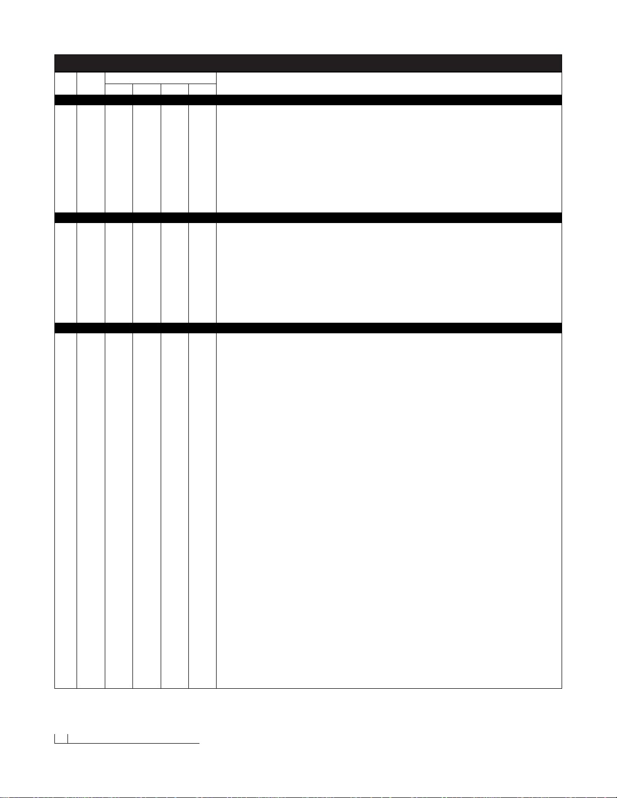
MODELS 700LD, 760LD, 760 & 800 PARTS LIST
20 Pa rts List (3 of 4)
700LD 760LD 760 800
Hydraulic Pump & Manifold Assembly Parts (Continued)
Snowplow Wire Harness Assembly Parts
Vehicle Wire Harness Assembly Parts
Ref. Part Build Quantity Part Description
No. No.
100 60052 6 6 6 6 Nut, Hex Jam, 1/2"-20 YZ
101 60168 1 1 1 1 Valve, Relief, 3000 PSI
102 60170 1 1 1 1 Valve, Spool, Three-Way, Two Position (85020341)
103 62115 1 1 1 1 Coil, DDL 10VDC
104 60166 1 1 1 1 Valve, Spool, Three-Way, Two Position (86020463)
105 60169 1 1 1 1 Valve, Flow Control (85002054)
106 60165 2 2 2 2 Valve, N.C., Two-Way (86020190)
N/A 62119 1 1 1 1 Coil Harness Assembly: (1) - 103, 62045, 62117, (4) - 62116, (5) - 99, (6) - 62096 & 62097
N/A 62045 1 1 1 1 Connector, Electric, Male, Plastic
N/A 62096 16 16 16 16 Seal, Cable, Silicone, Orange (18 AWG)
N/A 62097 6 6 6 6 Terminal, Male (18-16 AWG)
N/A 62116 4 4 4 4 Silicone Cavity Plug, White (18-16 AWG)
N/A 62117 1 1 1 1 Terminal, End Ring, 3/8" I.D.Copper, 8 Gauge
107A 62039 1 1 1 1 Wire Harness Assembly, Plow : (1) - 107, 108, 62006, 62046, (10) - 62096
107 62057 1 1 1 1 Wire Harness, Plow
108 62001 1 1 1 1 Weather Cap, Rubber, Plow Wire Har ness
N/A 62046 1 1 1 1 Connector, Electric, Female, Plastic
N/A 62006 1 1 1 1 Diode Board Assembly: (1) - 62007, 62090, 62092, 62094, 62095, (5) - 62091, 62093
N/A 62007 1 1 1 1 Cover, Clear, Diode Board
N/A 62090 1 1 1 1 Connector Body w/Gasket, Diode Board
N/A 62091 5 5 5 5 Seal, Cable, Silicone, Green (16 AWG)
N/A 62092 1 1 1 1 Plug, Cavity, Silicone, Green (16AWG)
N/A 62093 15 15 15 15 Terminal, Female (18-16 AWG)
N/A 62094 1 1 1 1 Circuit Board
N/A 62095 1 1 1 1 Secondary Lock, Six-Way
109A 62112 1 1 1 1 Wire Harness Assembly,Vehicle - Relay Version: (1) - 109, 110, 62124, 62113, 62125, 62008, 62009, 62056
(3) - 113, 62016, (4) - 62072
109 62111 1 1 1 1 Wire Harness, Vehicle - Relay Version
110 62000 1 1 1 1 Weather Cap, Rubber, Vehicle Wire Harness
N/A 62124 1 1 1 1 Fuse, 1/4" DIA. x 1-1/4" BUSS AGC 15A, 32V
N/A 62113 1 1 1 1 Main Lighting Harness - Relay Version
N/A 62125 1 1 1 1 Headlight Relay, 3PDT, 30A, 12V
N/A 62042 1 1 1 1 Power Contactor (Solenoid), Heavy Duty, Water-Resistant DC
N/A 61228 4 4 4 4 Nut, Hex Jam, 5/16"- 24 Z
N/A 61229 4 4 4 4 Nut, Hex Full, #10-32 Z
N/A 61230 2 2 2 2 Washer, Split Lock, #10 Z Medium
N/A 62056 1 1 1 1 Ground Wire, Power Contactor, 24"
N/A 62072 4 4 4 4 Terminal, End Ring, 3/8" I.D.Copper, 4 Gauge
N/A 62008 1 1 1 1 Fuse Clip, Mini
N/A 62009 1 1 1 1 Fuse Clip, Auto Blade
N/A 62016 3 3 3 3 Connector, Splice Lock (18-14 AWG)
N/A 62126 1 1 1 1 Ground Lead (Green/Yellow Wire), 24" with #10 Ring Terminal
N/A 62127 1 1 1 1 Switch Lead, On/Off Plow Light (Green/Yellow Wires), 24" with Two 1/4" Receptacles
N/A 62024 1 1 1 1 Switch,Toggle, DPDT, On-On, 20 Amps, 125V AC - Plow/Vehicle Headlights
111 61041 1 1 1 1 Bracket, Plow/Vehicle Headlight Toggle Switch
112 61088 1 1 1 1 Label, Plow/Vehicle Headlight Toggle Switch Bracket (BLZ 1008)
113 61031 5 5 5 5 Screw, Hex Washer Self-Drilling, 12-14 x 3/4"
114A 62058 2 2 2 2 Headlight Assembly,Plow (Specify Driver’s or Passenger’s Side): (1) - 115/116, 117-120, 62061
115 62059 1 1 1 1 Headlight, Plow, Driver’s Side
116 62060 1 1 1 1 Headlight, Plow, Passenger’sSide
117 62032 2 2 2 2 Wire Harness (with 5-pin plug), Plow Headlight
N/A 62061 2 2 2 2 Bulb, Sealed Beam Halogen, Glass, Plow Headlight (H6545/H4666)
N/A 62062 1 1 1 1 Corrosion Preventive Compound (2 fl.oz.)
118 61231 2 2 2 2 Adapter, Ball Stud Mount, Headlight
119 61232 2 2 2 2 Washer, Heavy Split Lock, 1/2"
120 61025 2 2 2 2 Nut, Hex, 1/2"-13 Grade 8 YZ
121 61166 2 2 2 2 Plug, Polyethylene, Black, 2-3/8" x 10-14 Gauge x 0.71"
122 39034 1 1 N/A N/A Light Tower - Models 700LD & 760LD
39032 N/A N/A 1 1 Light Tower - Models 760 & 800
123A 62073 1 1 1 1 Control Station Assembly, Joystick: (1) - 123-125, 127, (4) - 126
123 62074 1 1 1 1 Control Station, Joystick
124 61185 1 1 1 1 Base Plate, 1/8" ABS Plastic, Joystick Control Station
125 61127 1 1 1 1 Strap (Velcro® with 2" Metal D-Ring), Black, 61"
126 61254 4 4 4 4 Screw, Pan Head Machine, 8-32 x 3/4" Z
127 61174 1 1 1 1 Label, Control Station, Joystick (BLZ 1017)
128 30042 N/A N/A 1 1 Undercarriage Weldment, 1999 & Newer, Chevrolet/GMC 2500 Series
129 61128 1 1 N/A N/A Decal, Undercarriage Push Beam, 1-1/2" x 9-1/4" (BLZ 1004)
130 61085 N/A N/A 1 1 Decal, Undercarriage Push Beam, 2-1/4" x 13-7/8" (BLZ 1003)
Page 23
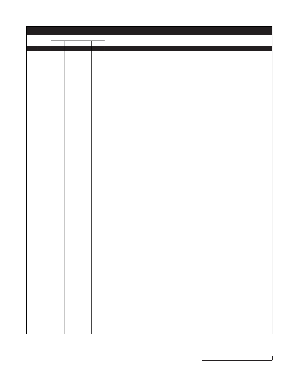
Ref. Part Build Quantity Part Description
No. No.
N/A 61355 1 N/A N/A N/A Kit, Hardware, Snowplow Assembly Parts - Model 700LD: (1) - 47-49, 84, (2) - 17-19, 21, 23 46, (3) - 45, (4) - 31 & 32
N/A 61354 N/A 1 N/A N/A Kit, Hardware, Snowplow Assembly Par ts - Model 760LD: (1) - 47-49, 84, (2) - 21, 23 46, (3) - 17-19, 45, (4) - 31 & 32
N/A 61353 N/A N/A 1 1 Kit, Hardware, Snowplow Assembly Parts - Models 760 & 800:(1) - 47-49, 84, (2) - 21, 23 46, (3) - 45, (4) -17-19, 31 & 32
N/A 60161 1 1 1 1 Kit, Hydraulic Adapter : (1) - 41, 43, 95, (2) - 93, 94, (3) - 36
N/A 60186 1 1 1 1 Kit, Hydraulic Hose : (1) - 37, 38, 40, 44
N/A 61257 1 N/A N/A N/A Kit, Hardware, Moldboard Cutting Edge - Model 700LD: (6) - 3-5
N/A 61255 N/A 1 1 1 Kit, Hardware, Moldboard Cutting Edge - Models 760LD, 760 & 800:(8) - 3-5
N/A 81042 1 N/A N/A N/A Cutting Edge (with Hardware Kit), Moldboard - Model 700LD: (1) - 81031, 61257
N/A 61256 N/A 1 N/A N/A Cutting Edge (with Hardware Kit), Moldboard - Model 760LD: (1) - 61165, 61255
N/A 61258 N/A N/A 1 N/A Cutting Edge (with Hardware Kit), Moldboard - Model 760: (1) - 61168, 61255
N/A 61259 N/A N/A N/A 1 Cutting Edge (with Hardware Kit), Moldboard - Model 800: (1) - 61164, 61255
Pa rts List (4 of 4) 21
MODELS 700LD, 760LD, 760 & 800 PARTS LIST
700LD 760LD 760 800
Miscellaneous Assembly Parts
Page 24
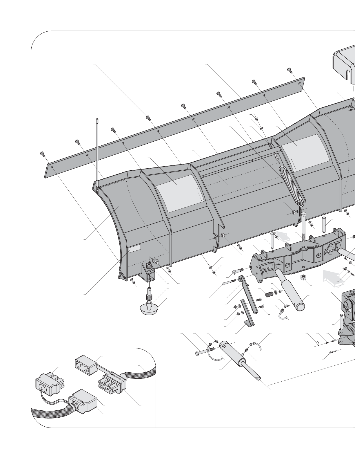
109A
109
110
107A
107
108
2
3
4
5
5
4
5
6A
6
7
8
10
12
13
14
15
16
17
18
1920
21
21
23
24A24
25
26
27
28
29
30
31
32
32
31
31
32
33
34
35
36
37
39 40
41
42
43
44
45
48
49
51
575859
65
Page 25
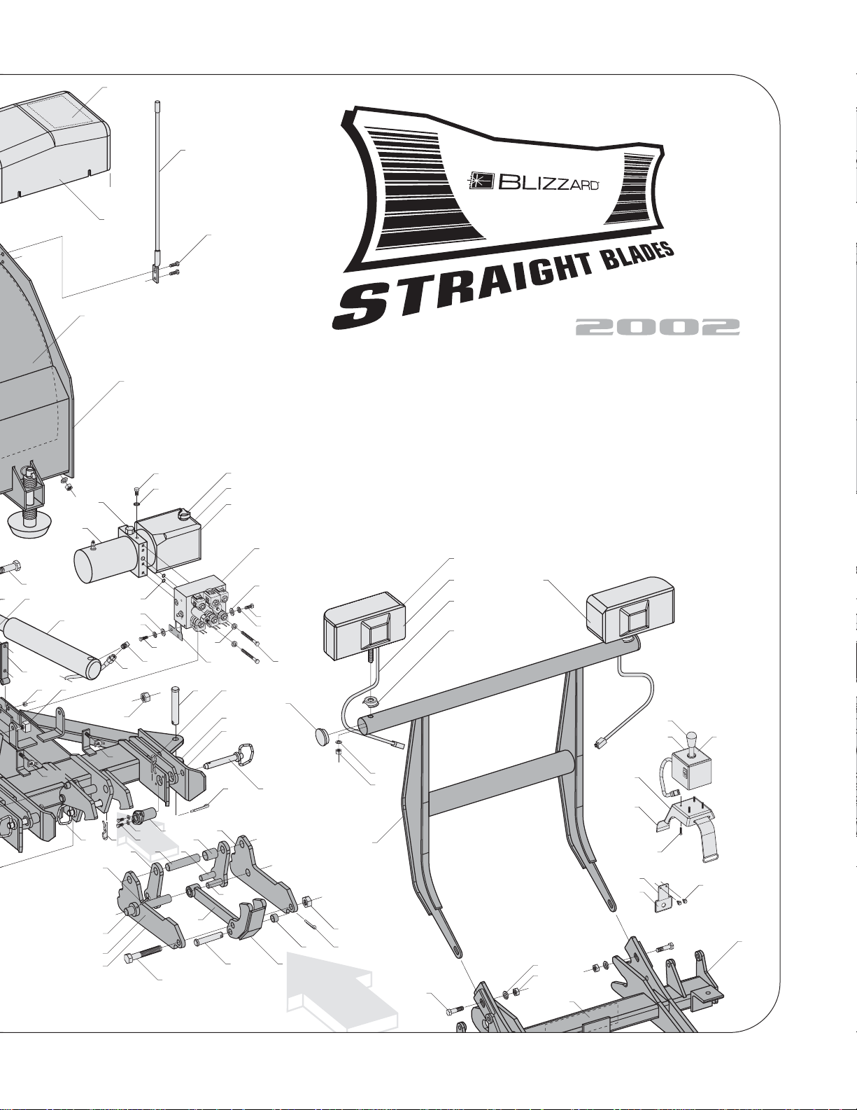
Blizzard Corporation reserves the right, under its Continuous Improvement Policy, to change construction or
design details and furnish equipment when so altered without reference to illustrations or specifications.
Blizzard Corporation offers a one-year limited warranty for all snowplows and accessories. Blizzard Corporation
does not warranty non-Blizzard snowplow service parts or accessories or damage resulting from the use of
these unauthorized items.
Blizzard Straight Blade Snowplows are protected by U.S. Patents 6,276,076 B1 and 6,393,737. Other patents pending.
Straight Blade Snowplow Assembly Schematic - Models 700LD, 760LD, 760 & 800
1
4
9A
9
11
21/22
23
27
5
31
32
35
38
36
45
45
46 47
50
52
47
88
89
47
53
54A
54
55
56
60
61 62
63 64
21
32
66A
66
67
68
69
70
71
72
73
74
75
75/76
77
78
79
80A
80
81
83
87
85
86
88
89
90
92A - SEE DETAIL ON PAGE 24.
63
91
111
112
113
114A
115 116
117
118
119
120
121
122
123A
123
124
125
126
127
128
129/130
46
84
82
Page 26
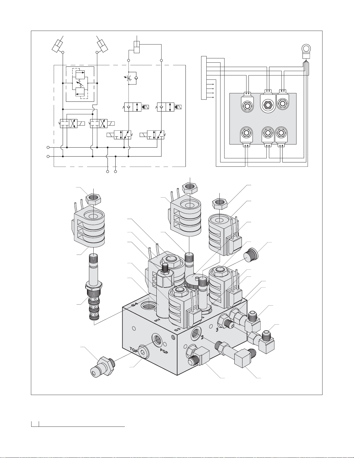
24 Manifold Detail w/Hyd. & Elec. Schematics
92
94
36
97
96
98
99
100
101
98
99
102
103
104
99
100
99
105
106
96
106
99
93
94
95
RIGHT ANGLE
LEFT ANGLE
3000 PSI
1
RV
2
S3 S4
TGP
PGP
S6
T1 P1
S5
S8
S7
FC
RAISE LOWER
34
LIFT CYL.
A
B
C
D
E
F
G
H
J
K
S5
S4
S8
S3
S6S5S8
S7
S4
S3
S7
S6
CONNECTS TO M5
SEE SCHEMATIC ON PAGE 27.
N/A
N/A
N/A
N/A
Page 27
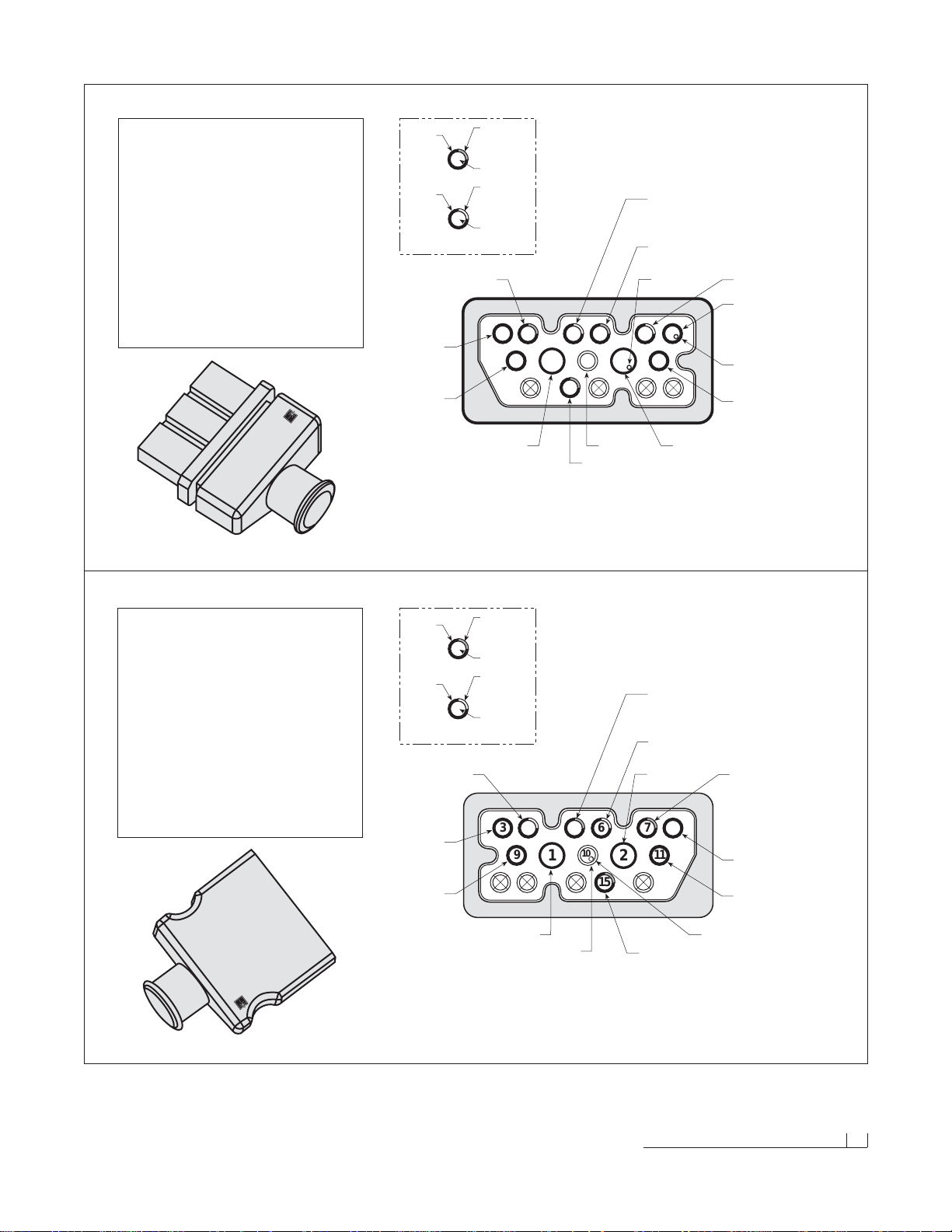
Diagram - Molded Plug Pin Locations 25
PLOW HARNESS PLUG (2002)
FACE VIEW LOOKING AT MALE CONNECTOR
VEHICLE HARNESS PLUG (2002)
FACE VIEW LOOKING AT FEMALE CONNECTOR
BLIZZARD HARNESS PLUG (PLOW)
PIN COLOR FUNCTION AWG
NO.
BLACK GROUND 4
N/A N/A N/A
2 RED 12 VOLT DC (+) 4
3BROWN PUMP SOLENOID 18
4 RED/WHITE RIGHT SLIDE BOX EXTEND 18
5 RED/BLACK RIGHT SLIDE BOX RETRACT 18
6 BLUE/WHITE LEFT SLIDE BOX EXTEND 18
7 BLUE/BLACK LEFT SLIDE BOX RETRACT 18
8 BLUE LEFT ANGLE 18
9 GREEN RIGHT ANGLE 18
WHITE LIFT 18
WHITE/BLACK LIFT 18
11 ORANGE FLOAT 18
12 N/A N/A N/A
13 N/A N/A N/A
14 N/A N/A N/A
15 PINK/BLACK 12 (+) VDC FUSED 18
16 N/A N/A 18
BLIZZARD HARNESS PLUG (VEHICLE)
UNIVERSAL 14 + 2 MOLD
PIN COLOR FUNCTION AWG
NO.
BLACK GROUND 4
BLACK GROUND 18
2 RED 12 VOLT DC (+) 4
BROWN/WHITE PUMP SOLENOID TO RING 18
BROWN PUMP SOLENOID TO MOLEX 18
4 RED/WHITE RIGHT SLIDE BOX EXTEND 18
5 RED/BLACK RIGHT SLIDE BOX RETRACT 18
6 BLUE/WHITE LEFT SLIDE BOX EXTEND 18
7 BLUE/BLACK LEFT SLIDE BOX RETRACT 18
8 BLUE LEFT ANGLE 18
9 GREEN RIGHT ANGLE 18
10 WHITE LIFT 18
11 ORANGE FLOAT 18
12 N/A N/A N/A
13 N/A N/A N/A
14 N/A N/A N/A
15 PINK/BLACK 12 (+) VDC FUSED 18
16 N/A N/A 18
1
3
FEMALE TERMINALS
MALE TERMINALS
4
STRIPE
COLOR
(BLACK)
WIRE
COLOR
(BLUE)
PIN NUMBER
STRIPE
COLOR
(WHITE)
WIRE
COLOR
(RED)
PIN NUMBER
EXAMPLE
7
1
6
15
STRIPE
COLOR
(BLACK)
WIRE
COLOR
(PINK)
PIN NUMBER
STRIPE
COLOR
(WHITE)
WIRE
COLOR
(BLUE)
PIN NUMBER
EXAMPLE
10
BLIZZARD
®
BLIZZARD
®
4
15
10
BLACK
RED/WHITE
GREEN
TOP
WHITE
RED
BLUE
ORANGE
BLUE/BLACK
BLUE/WHITE
RED/BLACK
PINK/BLACK
BROWN/WHITE
8
3
7 5
6
11 9
BROWN
12
1216 1314
BLACK
1
3
6
7
9
12
10
11
TOP
RED/WHITE
BLUE/WHITE
RED/BLACK
BROWN
GREEN
BLACK
RED
BLUE
ORANGE
PINK/BLACK
15
WHITE (DOUBLE)
BLUE/BLACK
3 8
54
10
1612 13 14
WHITE/BLACK
Page 28
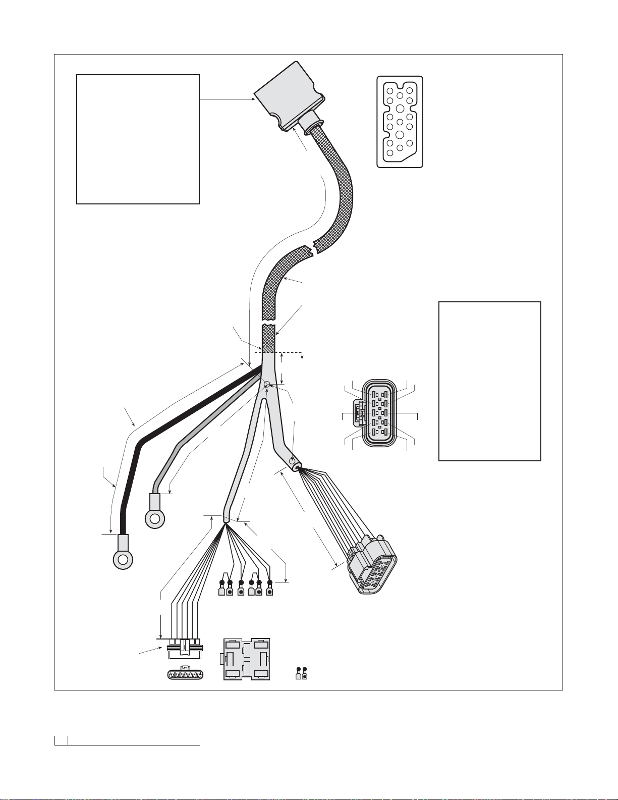
26 Diagram - Plow Harness
M2
24"
1"
20"
CLAMPING
LOCATION
VEHICLE HARNESS
JACKET MATERIAL
NYLON BRAID-RED WITH
BLACK & WHITE STRIPE
P/N 62057
3"
INSIDE HYDRAULIC
ENCLOSURE
5"
3"
3"
12"
A BCDEF
ORANGE/WHITE
WHITE
ORANGE
CAVITY PLUG
ORANGE/RED
ORANGE/BLACK
NOTE: GREASE FEMALE TERMINALS
DIODE PACK ASSEMBLY (P/N 62006)
DIODE PACK COVER, CLEAR - P/N 62007
CONNECTOR BODY W/GASKET - P/N 62090
SILICONE RUBBER CABLE SEAL - P/N 62091
SILICONE RUBBER CAVITY PLUG - P/N 62092
FEMALE TERMINAL (18-16 AWG) - P/N 62093
CIRCUIT BOARD - P/N 62094
SIX-WAY SECONDARY LOCK - P/N 62095
HIGH AMP WIRES
COLORS (PIN 1 - BLACK, PIN 2 - RED)
WIRE (SGT 4 AWG)
END RING TERMINALS (3/8" I.D.) - P/N 62072
PLOW HARNESS (2002)
WITH MOLDED PLUG
P/N 62039
NOT DRAWN TO SCALE
UNLESS OTHERWISE SPECIFIED
ALL DIMENSIONS IN INCHES
END VIEW
LOOKING AT CONNECTOR
NOTE: SEE DETAIL ON PAGE 25.
8
7
11
16
21
65 43
9
10
15 14 13 12
8 "
PLASTIC ELECTRIC CONNECTOR, FEMALE - P/N 62046
SILICONE RUBBER CABLE SEAL - P/N 62096
FEMALE TERMINAL (18-16 AWG) - P/N 62093
RED
BLACK
TOP
7
31
56
2
8
4
FRONT
VIEW
(5) PINK/BLACK
(6) PINK/BLACK
(3) WHITE
(1) BROWN
(2) BROWN
(4) ORANGE/RED
(7) AND (8) NOT USED
OTTO CONNECTOR
AMP TERMINALS
(18-14 AWG)
(TWO 18-14 AWG)
PACKARD GT 280 ELECTRIC CONNECTOR (PLOW)
PIN COLOR FUNCTION AWG
NO.
A ORANGE/BLACK (S5) LOWER/FLOAT 18
B ORANGE/WHITE (S7) LIFT/FLOAT 18
CWHITE/BLACK (S6) LIFT 18
D ORANGE/RED (S8) HITCH LOWER 18
E GREEN (S4) ANGLE RIGHT 18
F BLUE (S3) ANGLE LEFT 18
G BLUE/BLACK (S9) LEFT SLIDE BOX RET. 18
H BLUE/WHITE (S10) LEFT SLIDE BOX EXT. 18
J RED/BLACK (S1) RIGHT SLIDE BOX RET. 18
K RED/WHITE (S2) RIGHT SLIDE BOX EXT. 18
A
B
E
D
C
K
J
H
G
F
END VIEW
LOOKING AT CONNECTOR
M5
B1
B2
M4
M10
BLIZZARD PLUG (VEHICLE)
UNIVERSAL 14 + 2 MOLD
PIN COLOR FUNCTION AWG
NO.
BLACK GROUND 4
N/A N/A N/A
2 RED 12 VDC (+) 4
3BROWN PUMP SOLENOID 18
4 RED/WHITE RIGHT BOX EXTEND 18
5 RED/BLACK RIGHT BOX RETRACT 18
6 BLUE/WHITE LEFT BOX EXTEND 18
7 BLUE/BLACK LEFT BOX RETRACT 18
8 BLUE LEFT ANGLE 18
9 GREEN RIGHT ANGLE 18
WHITE LIFT 18
WHITE/BLACK LIFT 18
11 ORANGE FLOAT 18
12 N/A N/A N/A
13 N/A N/A N/A
14 N/A N/A N/A
15 PINK/BLACK 12 VDC (+) FUSED 18
16 N/A N/A N/A
1
10
Page 29
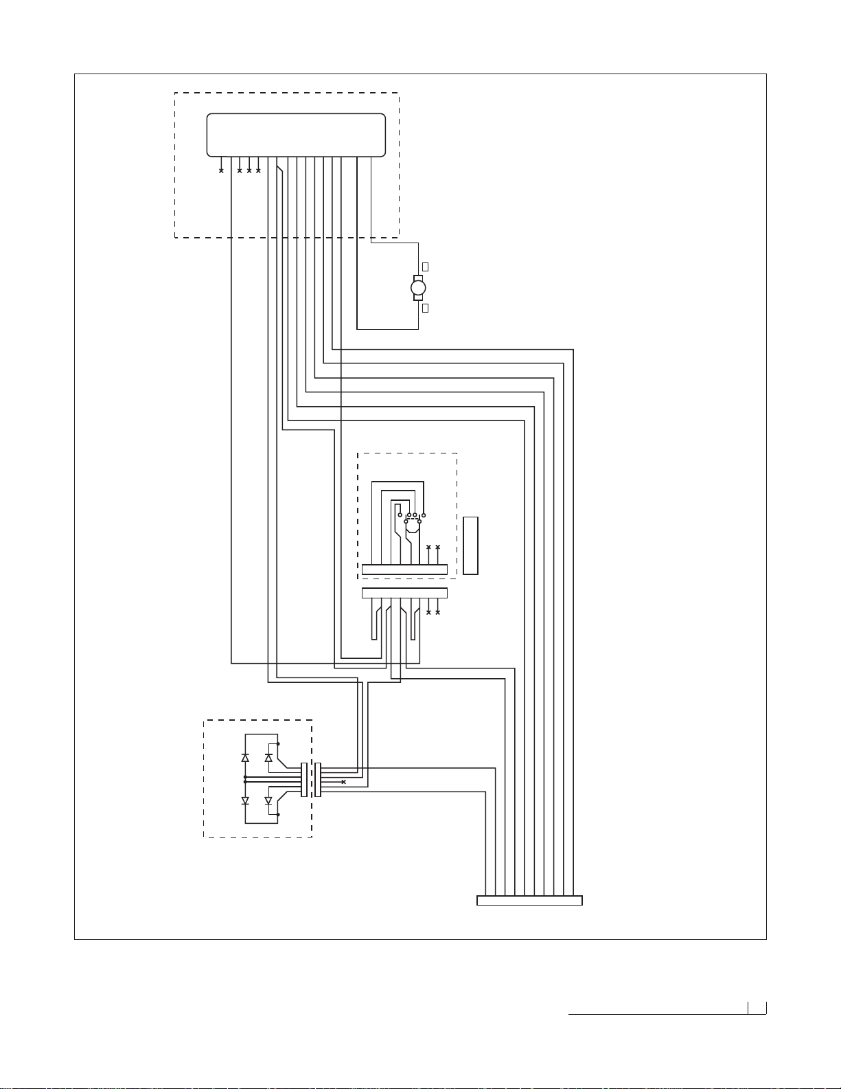
Plow Harness Wire Schematic 27
PLOW HARNESS WIRE SCHEMATIC (2002)
D3 D1
D4 D2
M3
M4
A B C D E F
1
2
3
4
5
6
123456
WHITE
ORANGE
ORANGE/RED
A ORANGE/BLACK
B ORANGE/WHITE
C WHITE/BLACK
D ORANGE/RED
E GREEN
F BLUE
G BLUE/BLACK
H BLUE/WHITE
J RED/BLACK
K RED/WHITE
ABCDEFGHJ
K
M5
MANIFOLD CONNECTOR
PACKARD ELECTRIC CONNECTOR
1 ORANGE/BLACK = A
2 ORANGE/RED = B
3 NOT USED = C
4 ORANGE = D
5 WHITE = E
6 ORANGE/WHITE = F
WHITE/BLACK
ORANGE/RED
ORANGE/RED
ORANGE/RED
PINK/BLACK
PINK/BLACK
WHITE
WHITE
BROWN
BROWN
1234567
8
M10
1234567
8
5
6
4332
1
S1
HITCH SWITCH
DPDT (ON)-OFF-(ON)
NOTE: WHITE IS ON
TOP TERMINAL
BROWN
WHITE
PINK/BLACK
PINK/BLACK PINK/BLACK
ORANGE
WHITE/BLACK
WHITE
GREEN
BLUE
BLUE/BLACK
BLUE/WHITE
RED/BLACK
RED/WHITE
BROWN
GREEN
BLUE
BLUE/BLACK
BLUE/WHITE
RED/BLACK
RED/WHITE
RED
RED BLACK
B2 B2
B2
B1
PUMP MOTOR
MOTOR 1
PINK/BLACK
ORANGE
WHITE/BLACK
WHITE
GREEN
BLUE
BLUE/BLACK
BLUE/WHITE
RED/BLACK
RED/WHITE
BROWN
16
1514131211
N/A
VDC FUSED
N/A
N/A
N/A
FLOAT
10
9876543
2
1
LIFT
RIGHT ANGLE
LEFT ANGLE
LT. SLIDE RET.
LT. SLIDE EXT.
RT. SLIDE RET.
PUMP SOL.
POS
NEG
PS. SLIDE EXT.
RED #4 AWG
BLACK #4 AWG
M2
GREEN
BLUE
BLUE/BLACK
BLUE/WHITE
RED/BLACK
RED/WHITE
SEE VEHICLE HARNESS WIRE SCHEMATIC
Page 30
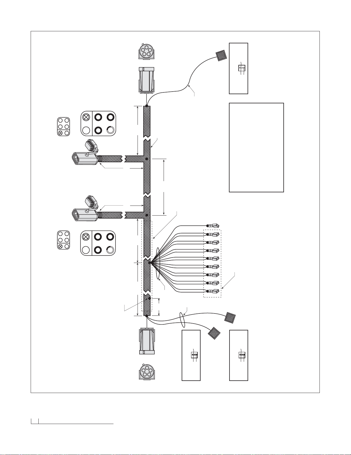
28 Diagram - Main Lighting Harness
MAIN LIGHTING HARNESS (2002)
RELA Y VERSION
P/N 62113
NOT DRAWN TO SCALE
UNLESS OTHERWISE SPECIFIED
ALL DIMENSIONS IN INCHES
E
A = COMMON (WHITE/RED)
B = HIGH BEAM FEED (YELLOW)
C = LOW BEAM FEED (LT. GREEN)
D = HIGH BEAM (YELLOW/RED)
E = LOW BEAM (LT. GREEN/RED)
BLACK/WHITE
WHITE/RED
WHITE/RED
LT. GREEN
LT. GREEN
YELLOW
YELLOW
LT. GREEN/BLACK
LT. GREEN/BLACK
YELLOW/BLACK
YELLOW/BLACK
GREEN/RED
GREEN/RED
YELLOW/RED
YELLOW/RED
WHITE
WHITE
A
B
C D
F
VEHICLE
A = COMMON (WHITE)
B = NOT USED
C = RIGHT TURN (PINK)
D = RUN (GRAY-3)
E = LOW BEAM (LT. GREEN/BLACK)
F = HIGH BEAM (YELLOW/BLACK)
END VIEW
LOOKING AT
CONNECTOR
A
B
C D
F
VEHICLE
LEFT
(WHITE) COMMON = A
NOT USED = B
(VIOLET) LEFT TURN = C
(GRAY-2) RUN = D
(LT. GREEN/BLACK) LOW BEAM = E
(YELLOW/BLACK) HIGH BEAM = F
END VIEW
LOOKING AT
CONNECTOR
28"
18" 18"
A
B
C
D
E
A
B
C
D
E
5"
24"24"14"
END VIEW
LOOKING AT
CONNECTOR
FFM
FFM
VEHICLE
END VIEW
LOOKING AT
CONNECTOR
FFM
FFM
VEHICLE
5"
LOCATION OF BLACK/WHITE,
GRAY-1, GRAY-2 & GRAY-3
WIRE SPLICE
26"
26"
A = COMMON (WHITE/RED)
B = HIGH BEAM FEED (YELLOW)
C = LOW BEAM FEED (LT. GREEN)
D = HIGH BEAM (YELLOW/RED)
E = LOW BEAM (LT. GREEN/RED)
RIGHT
JACKET MATERIAL
BLACK NYLON BRAID
BLUE SPLICE LOCK CONNECTOR
P/N 62016
OTHER WIRE
PINK WIRE
OTHER WIRE
TURN (PINK)
TURN (VIOLET)
BLUE SPLICE LOCK CONNECTOR
P/N 62016
OTHER WIRE
VIOLET WIRE
OTHER WIRE
BLUE SPLICE LOCK CONNECTOR
P/N 62016
OTHER WIRE
GRAY WIRE
OTHER WIRE
RUN (GRAY-1)
E
ALTERNATIVE B SPLICE
ALTERNATIVE A DOUBLE TERMINATE
COLOR FUNCTION AWG
WHITE/RED LIGHT COMMON 16
WHITE LIGHT COMMON 16
LT. GREEN LOW BEAM 16
YELLOW HIGH BEAM 16
LT. GREEN/RED LOW BEAM VEHICLE 16
YELLOW/RED HIGH BEAM VEHICLE 16
LT. GREEN/BLACK LOW BEAM PLOW 16
YELLOW/BLACK HIGH BEAM PLOW 16
GRAY PARK/RUN 18
VIOLET LEFT TURN 18
PINK RIGHT TURN 18
Page 31
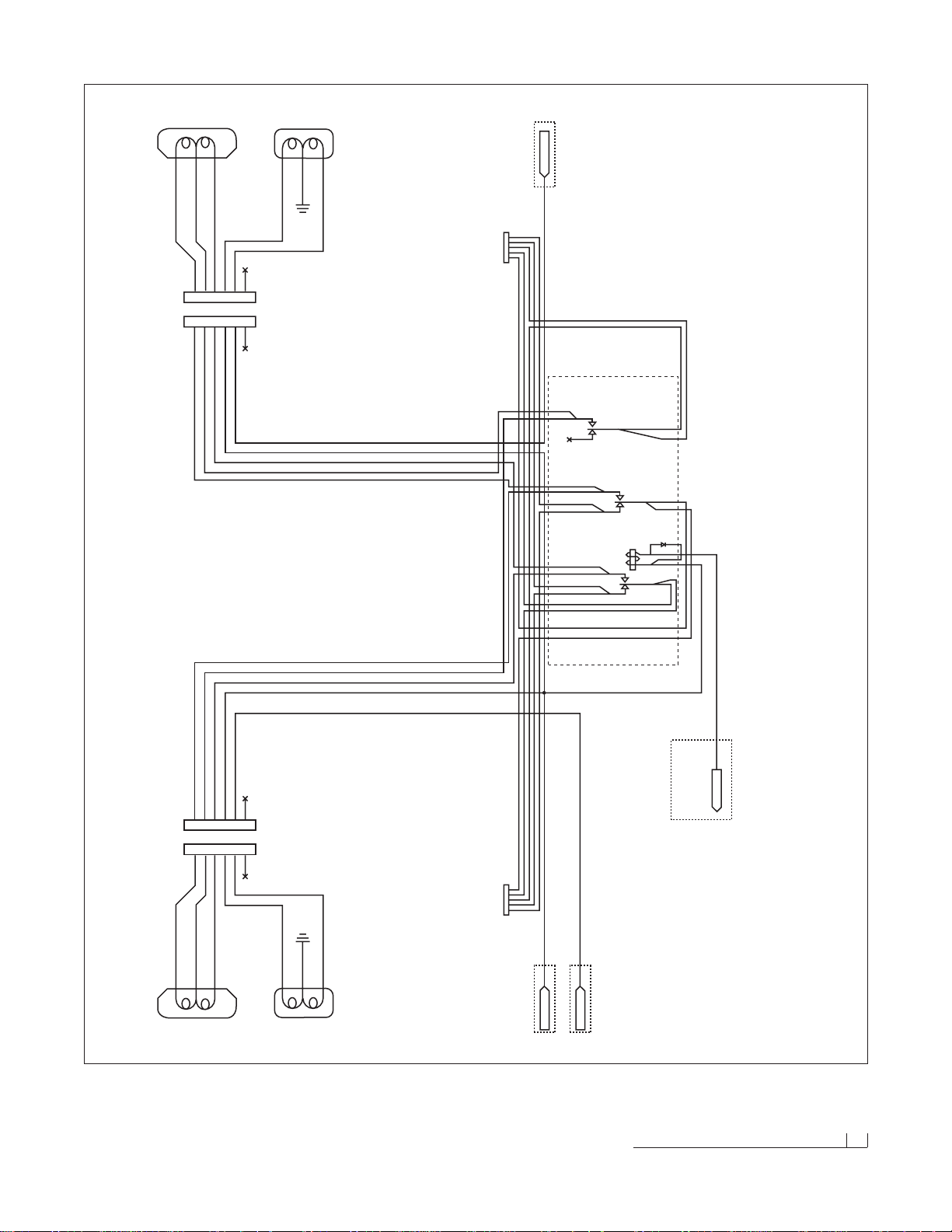
Main Lighting Harness Wire Schematic 29
MAIN LIGHTING HARNESS - RELAY VERSION WIRE SCHEMATIC (2002)
1 LOW BEAM (LT. GREEN/BLACK) = E
2 WHITE (COMMON + or –) = A
3 HIGH BEAM (YELLOW/BLACK) = F
4 PARK - RUN (GRAY) = D
5 TURN - LEFT (VIOLET) or RIGHT (PINK) = C
6 N/A = NOT USED
VIOLET
1 E
2 A
3 F
4 D
5 C
6 N/A
GRAY
YELLOW/BLACK
WHITE
LT. GREEN/BLACK
1 LOW BEAM (LT. GREEN/BLACK) = E
2 WHITE (COMMON + or –) = A
3 HIGH BEAM (YELLOW/BLACK) = F
4 PARK - RUN (GRAY) = D
5 TURN - LEFT (VIOLET) or RIGHT (PINK) = C
6 N/A = NOT USED
LT. GREEN/BLACK
1 E
2 A
3 F
4 D
5 C
6 N/A
GRAY
YELLOW/BLACK
WHITE
PINK
PACKARD ELECTRIC CONNECTOR (PE)
1 LOW BEAM (LT. GREEN/RED) = E
2 HIGH BEAM (YELLOW/RED) = D
3 WHITE/RED (COMMON + or -) = A
4 HIGH BEAM FEED (YELLOW) = B
5 LOW BEAM FEED (LT. GREEN) = C
PE
PACKARD ELECTRIC CONNECTOR (PE)
1 LOW BEAM (LT. GREEN/RED) = E
2 HIGH BEAM (YELLOW/RED) = D
3 WHITE/RED (COMMON + or -) = A
4 HIGH BEAM FEED (YELLOW) = B
5 LOW BEAM FEED (LT. GREEN) = C
PE
LT. GREEN
YELLOW
WHITE/RED
YELLOW/RED
LT. GREEN/RED
GRAY
VIOLET
PINK
LT. GREEN
YELLOW
WHITE/RED
YELLOW/RED
LT. GREEN/RED
LT. GREEN
LT. GREEN
YELLOW
YELLOW
YELLOW/RED
YELLOW/RED
YELLOW/BLACK
YELLOW/BLACK
LT. GREEN/RED
LT. GREEN/RED
LT. GREEN/BLACK
LT. GREEN/BLACK
N/A
WHITE
WHITE
WHITE/RED
WHITE/RED
BLACK/WHITE
GREEN/YELLOW
VEHICLE HARNESS
M16
R1
SIX PRONG
M17
L5
PLOW RIGHT HEAD LAMP
LT. GREEN/BLACK LOW BEAM
GRAY PARK
Vcc
PLOW RIGHT TURN LAMP
L6
BLACK GROUND
YELLOW/BLACK HIGH BEAM
BLACK GROUND
PINK TURN
1 E
2 A
3 F
4 D
5 C
6 N/A
M14
L7
PLOW LEFT HEAD LAMP
LT. GREEN/BLACK LOW BEAM
GRAY PARK
Vcc
PLOW LEFT TURN LAMP
L8
BLACK GROUND
YELLOW/BLACK HIGH BEAM
BLACK GROUND
VIOLET TURN
1 E
2 A
3 F
4 D
5 C
6 N/A
M15
L1
SIX PRONG
NOTE: CONNECTORS M14 TO M17 ARE
SIX PRONG SQUARE RUBBER FEMALE
RUN LIGHTS
LEFT TURN
RIGHT TURN
NC
NO
(HIGH)
COMM
CO1
CO2
NC
NO
COMM
(LOW)
(GROUND)
NC
NO
COMM
3P/DT2/ST1 RELAY
(DIODE LOCATED
INSIDE OF RELAY)
GROUND (-)
Page 32
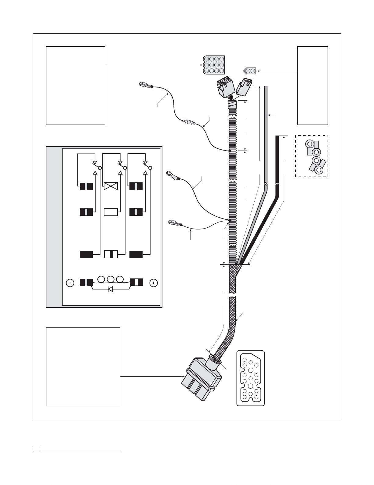
30 Diagram - Vehicle Harness
VEHICLE HARNESS (2002)
RELA Y VERSION
P/N 62111
NOT DRAWN TO SCALE
UNLESS OTHERWISE SPECIFIED
ALL DIMENSIONS IN INCHES
30"
1/2" SPLIT LOOM TUBING
HIGH AMP WIRES
BLACK (PIN 1) - 82" LONG
RED (PIN 2) - 82" LONG
WIRE (SGT 4 AWG)
END RING TERMINALS (3/8" I.D.)
NOTE: GREASE FEMALE TERMINALS
TO PUMP SOLENOID
BROWN/WHITE
AWG 18
100" LONG
CONNECTS
TO M1 PIN #3
JACKET MATERIAL
NYLON BRAID
RED WITH BLACK &
WHITE STRIPE
3
4
9
13
1
2
56 78
11
10
14 15 1612
END VIEW
LOOKING AT
CONNECTOR
NOTE: SEE DETAIL ON PAGE 25.
A1
A2
82"
82"
83" 20"
16"
M1
GREEN/YELLOW
AWG 18
10" LONG
1 2 3
4 5 6
7 8 9
10 11 12
1
2
RED - AWG 18
20" LONG
RED-2
RED - AWG 18
8" LONG
CONNECTS TO
MOLEX PIN #3
RED-1
FUSE HOLDER
BUSS BP/HHB
ACCEPTS AGC 10
FUSES 10-15 AMP
P/N 62124
END VIEW
LOOKING AT
CONNECTOR
END VIEW
LOOKING AT
CONNECTOR
“MOLEX” FREE HANGING RECEPTACLE
.093 (2) PIN POWER CONNECTOR
WITH “MOLEX” FEMALE TERMINAL
PIN COLOR FUNCTION AWG
NO.
1 GREEN/YELLOW RELAY GROUND 18
2 N/A N/A N/A
“MOLEX” FREE HANGING RECEPTACLE
.093 (12) PIN POWER CONNECTOR
WITH “MOLEX” FEMALE TERMINAL
PIN COLOR FUNCTION AWG
NO.
1 RED/WHITE RIGHT SLIDE BOX EXTEND 18
2 RED/BLACK RIGHT SLIDE BOX RETRACT 18
3 RED SWITCH 12 VOLT + 18
4 ORANGE FLOAT 18
5 BLUE/WHITE LEFT SLIDE BOX EXTEND 18
6 BLUE/BLACK LEFT SLIDE BOX RETRACT 18
7 BLACK GROUND 18
8 WHITE LIFT 18
9BROWN PUMP SOLENOID 18
10 PINK/BLACK 12 (+) DC FUSED 18
11 GREEN RIGHT ANGLE 18
12 BLUE LEFT ANGLE 18
A
B
G/Y
BK/W
Y7
W/R 8
LT. G 9
HIGH
GROUND
LOW
Y/B 4
WHITE 5
Y/R 1
N/A 2
LT. G/B 6
LT. G/R
3
3P/DT2/ST1-RELAY (30 AMPS) 12 VOLTS
BLIZZARD PLUG (VEHICLE)
PIN COLOR FUNCTION AWG
NO.
BLACK (A1) GROUND 4
BLACK GROUND 18
2 RED (A2) 12 VDC (+) 4
BROWN/WHITE PUMP SOLENOID TO RING 18
BROWN PUMP SOLENOID TO MOLEX 18
4 RED/WHITE RIGHT BOX EXTEND 18
5 RED/BLACK RIGHT BOX RETRACT 18
6 BLUE/WHITE LEFT BOX EXTEND 18
7 BLUE/BLACK LEFT BOX RETRACT 18
8 BLUE LEFT ANGLE 18
9 GREEN RIGHT ANGLE 18
10 WHITE LIFT 18
11 ORANGE FLOAT 18
12 N/A N/A N/A
13 N/A N/A N/A
14 N/A N/A N/A
15 PINK/BLACK 12 VDC (+) FUSED 18
16 N/A N/A N/A
1
3
AAS-3 HEADLIGHT RELAY
w/SURGE SUPPRESSION
VENDOR P/N 90-9055-00-B-TR/SS
BLIZZARD P/N 62125
3/8" RING TERMINAL
(4) SUPPLIED LOOSELY
P/N 62072
Page 33
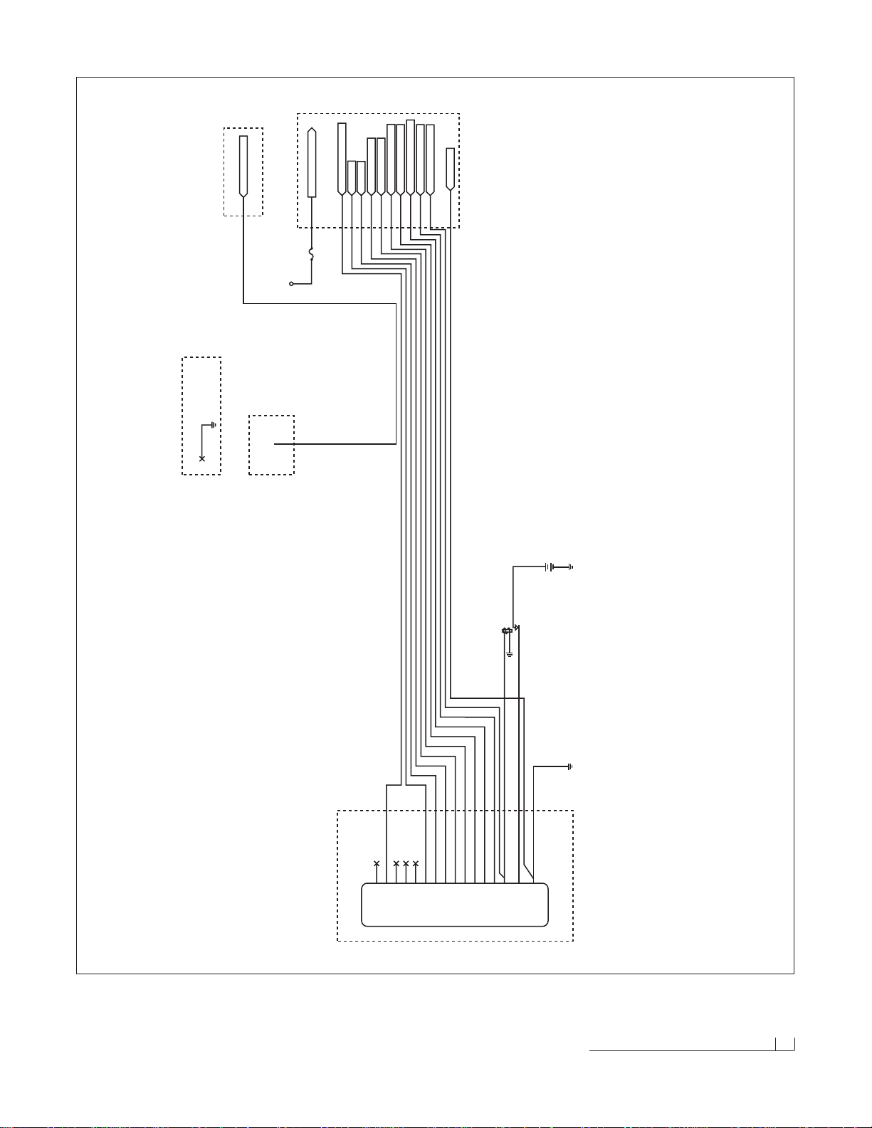
Vehicle Harness Wire Schematic 31
VEHICLE HARNESS - RELAY VERSION WIRE SCHEMATIC (2002)
N/A
VDC FUSED
N/A
N/A
N/A
FLOAT
LIFT
RIGHT ANGLE
LEFT ANGLE
LEFT BOX RET.
LEFT BOX EXT.
RIGHT BOX RET.
RIGHT BOX EXT.
PUMP SOL.
POS
NEG
16151413121110
9876543
2
PINK/BLACK
ORANGE
WHITE
GREEN
BLUE
BLUE/BLACK
BLUE/WHITE
RED/BLACK
RED/WHITE
BROWN
RED #4 AWG
BLACK #4 AWG
1
PINK/BLACK
ORANGE
WHITE
GREEN
BLUE
BLUE/BLACK
BLUE/WHITE
RED/BLACK
RED/WHITE
BROWN
BLACK
RED
BLACK
M1
A1
SEE PLOW HARNESS WIRE SCHEMATIC
A2
BROWN/WHITE A10
PUMP RELAY
BT1
VEHICLE BATTERY
K1
BROWN/WHITE
BLACK (18 AWG)
(10) SWITCHED 12 V DC
(4) FLOAT
(8) LIFT
(11) RIGHT ANGLE
(12) LEFT ANGLE
(6) LEFT BOX RETRACT
(5) LEFT BOX EXTEND
(2) RIGHT BOX RETRACT
(1) RIGHT BOX EXTEND
(9) PUMP SOLENOID
12-PIN MATRIX
PINK/BLACK
ORANGE
WHITE
GREEN
BLUE
BLUE/BLACK
BLUE/WHITE
RED/BLACK
RED/WHITE
BROWN
(3) SWITCH 12 VOLT +
RED
(7) GROUND
BLACK
PINK/BLACK
ORANGE
WHITE
GREEN
BLUE
BLUE/BLACK
BLUE/WHITE
RED/BLACK
RED/WHITE
BROWN
BLACK
A9
RED
FUSE 10 AMP
Vcc
F1
(1) RELAY GROUND
GREEN/YELLOW
GREEN/YELLOW
BLACK/WHITE
2-PIN MATRIX
(RELAY)
.250 RECEPTICLE
NOTE: ALL GROUNDS HAVE BLACK WIRE
BLACK
Page 34
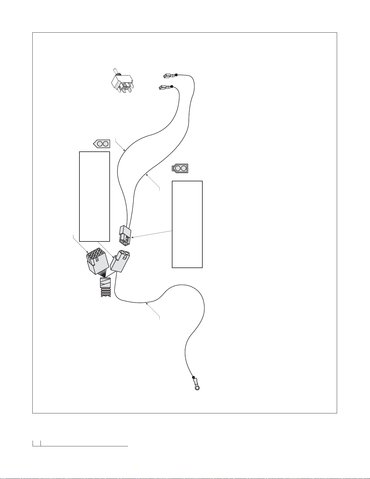
32 Diagram - On/Off Switch Leads & Ground
ON/OFF SWITCH LEADS & GROUND LEAD (2002)
FOR BLIZZARD RELAY HARNESS WHEN USING A CONTROL STATION
WITH A SINGLE POWER SWITCH
NOT DRAWN TO SCALE
UNLESS OTHERWISE SPECIFIED
ALL DIMENSIONS IN INCHES
TO CONTROL
“AMP” CONNECTOR
(2) PIN POWER CONNECTOR
WITH “MOLEX” MALE TERMINAL
PIN COLOR FUNCTION AWG
NO.
1 GREEN/YELLOW RELAY GROUND (FROM SWITCH) 18
2 GREEN/YELLOW RELAY GROUND (FROM SWITCH) 18
END VIEW
LOOKING AT
CONNECTOR
1
2
“MOLEX” FREE HANGING RECEPTACLE
.093 (2) PIN POWER CONNECTOR
WITH “MOLEX” FEMALE TERMINAL
PIN COLOR FUNCTION AWG
NO.
1 GREEN/YELLOW RELAY GROUND (FROM VEH. HARNESS) 18
2 GREEN/YELLOW RELAY GROUND (FROM #10 RING TERM.) 18
1
2
END VIEW
LOOKING AT
CONNECTOR
GREEN/YELLOW
12" LONG
GREEN/YELLOW
12" LONG
.250 RECEPTACLE
.250 RECEPTACLE
SWITCH LEADS
P/N 62127
GROUND LEAD
P/N 62126
GREEN/YELLOW
24" LONG
#10 RING TERMINAL
GROUND TO VEHICLE
VEHICLE HARNESS
SEE DIAGRAM ON PAGE 30.
DPDT TOGGLE SWITCH
P/N 62024
NOTE: SEE INSTALLATION
INSTRUCTIONS ON PAGE 11.
Page 35
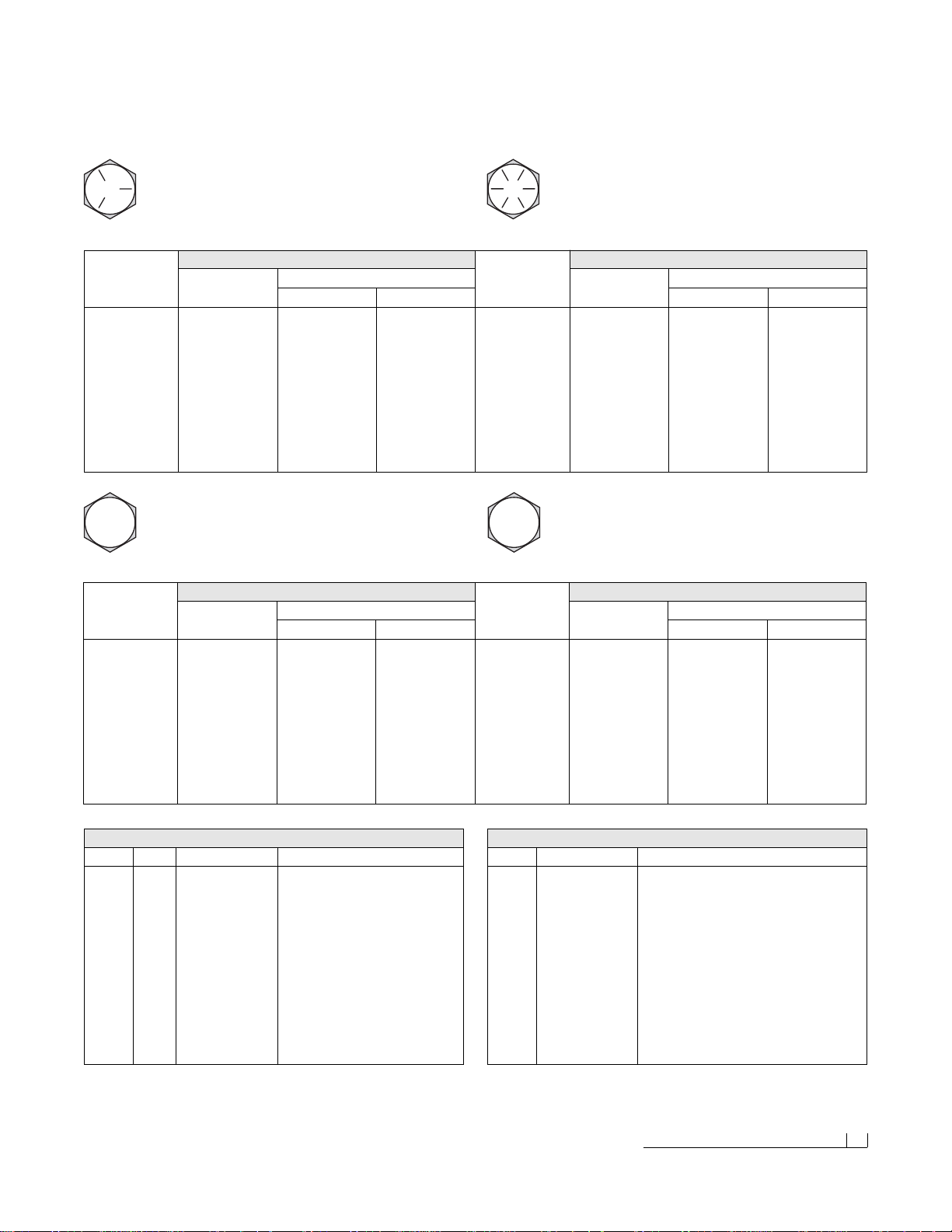
1. Make sure the tubing and threads are clean.
2. Lubricate the threads with 10W hydraulic oil.
3. Hand tighten the nut/sleeve to appox.30 in-lbs.
4. Make alignment marks on the nut and fitting.
5. Proceed to tighten to turns or ft-lb values.
6. When fully tightened make a 2nd set of alignment marks at the fully tightened position.
Note:Torque values specified are for threads
lubricated with 10W hydraulic oil.
Sizes -02 through -08 are less tolerant to overtorque abuse.This will reduce the clamping force
resulting in loss of seal and reduction in flow.
37˚ JIC Flare Torque Values
Turns Size ft-lbs min./max. Assembly Steps w/Visual Check
N/A -02 6 - 7
N/A -03 8 - 9
2 -04 11 - 12
2 -05 14 - 15
1-1/2 -06 18 - 20
1-1/2 -08 36 - 39
1-1/2 -10 57 - 63
1-1/4 -12 79 - 88
1 -14 94 - 103
1 -16 108 - 113
1 -20 127 - 133
1 -24 158 - 167
1 -32 245 - 258
Metric Class 8.8 Metric Class 10.9
Tightening Tor que Tightening Tor que
“Lubricated” “Dry” “Lubricated” “Dry”
5 6177 4.63 N-m 6.18 N-m 5 8840 6.63 N-m 8.84 N-m
6 8743 7.87 N-m 10.5 N-m 6 12512 11.3 N-m 15.0 N-m
7 12570 13.2 N-m 17.6 N-m 7 17990 18.9 N-m 25.2 N-m
8 15921 19.1 N-m 25.5 N-m 8 22784 27.3 N-m 36.5 N-m
10 25230 37.8 N-m 50.5 N-m 10 36105 54.1 N-m 72.2 N-m
12 36670 66.0 N-m 88.0 N-m 12 52475 94.5 N-m 125 N-m
14 50025 105 N-m 140 N-m 14 71587 150 N-m 200 N-m
16 70650 170 N-m 226 N-m 16 97732 235 N-m 313 N-m
18 86400 233 N-m 311 N-m 18 119520 323 N-m 430 N-m
20 110250 330 N-m 441 N-m 20 152513 458 N-m 610 N-m
Tor que Specifications 33
Torque Specifications
SAE J429 - Grade 5 SAE J429 - Grade 8
Tightening Tor que Tightening Tor que
“Lubricated” “Dry” “Lubricated” “Dry”
1/4-20 2,000 75 in-lbs 100 in-lbs 1/4-20 2,850 107 in-lbs 143 in-lbs
5/16-18 3,350 157 in-lbs 210 in-lbs 5/16-18 4,700 220 in-lbs 305 in-lbs
3/8-16 4,950 23 ft-lbs 31 ft-lbs 3/8-16 6,950 32.5 ft-lbs 44 ft-lbs
7/16-14 6,800 37 ft-lbs 50 ft-lbs 7/16-14 9,600 53 ft-lbs 70 ft-lbs
1/2-13 9,050 57 ft-lbs 75 ft-lbs 1/2-13 12,800 80 ft-lbs 107 ft-lbs
9/16-12 11,600 82 ft-lbs 109 ft-lbs 9/16-12 16,400 115 ft-lbs 154 ft-lbs
5/8-11 14,500 113 ft-lbs 151 ft-lbs 5/8-11 20,300 159 ft-lbs 21 ft-lbs
3/4-10 21,300 200 ft-lbs 266 ft-lbs 3/4-10 30,100 282 ft-lbs 376 ft-lbs
7/8-9 29,435 321 ft-lbs 430 ft-lbs 7/8-9 41,550 454 ft-lbs 606 ft-lbs
1-8 38,600 482.5 ft-lbs 640 ft-lbs 1-8 54,540 680 ft-lbs 900 ft-lbs
Clamp Loads
(lbs.)
Clamp Loads
(lbs.)
Nominal
Thread
Size
Nominal
Thread
Size
Grade Identification Marking for J429 - Grade 5 Bolt
• Material: Medium carbon steel: quenched and tempered
• Minimum Proof Strength: 85,000 psi
• Minimum Tensile Strength: 120,000 psi
• Core Hardness Rockwell (min.): C25, (max.): C34
• Minimum Yield Strength:92,000 psi
Grade Identification Marking for J429 - Grade 8 Bolt
• Material: Medium carbon alloy steel:quenched and tempered
• Minimum Proof Strength: 120,000 psi
• Minimum Tensile Strength: 150,000 psi
• Core Hardness Rockwell (min.): C33, (max.): C39
• Minimum Yield Strength:130,000 psi
8.8
Clamp Loads
(Newton)
Clamp Loads
(Newton)
Diameter
(millimeters)
Diameter
(millimeters)
Grade Identification Marking for Metric - Grade 8.8 Bolt
• Material: Medium carbon steel: quenched and tempered
• Minimum Proof Strength: 580 MPa
• Minimum Tensile Strength: 800 MPa
• Core Hardness Rockwell (min.): C22, (max.): C32
• Minimum Yield Strength: 640 MPa
10.9
Grade Identification Marking for Metric - Grade 10.9 Bolt
• Mater ial: Low carbon alloy steel: quenched and tempered
• Minimum Proof Strength: 830 MPa
• Minimum Tensile Strength: 1040 MPa
• Core Hardness Rockwell (min.): C32, (max.): C39
• Minimum Yield Strength: 940 MPa
O-Ring Boss Torque Values
Size ft-lbs min./max. O-Ring Boss Assembly
-02 6 - 7
-03 8 - 10
-04 13 - 15
-05 17 - 21
-06 22 - 25
-08 40 - 43
-10 43 - 57
-12 68 - 75
-14 90 - 99
-16 112 - 123
-20 146 - 200
-24 154 - 215
-32 218 - 290
1. Verify the port, O-ring, sealing surfaces, and threads are
clean and free of damage.
2. Lubricate the threads and the O-ring with 10W hydraulic oil.
3. For an adjustable O.R.B., completely back-off the lock nut
and the washer.
4. Hand tighten the fitting until it contacts the port spotface.
Point the elbow or tee in the desired direction and hold.
5. Proceed to tighten to the proper specified torque value.
Note:Torque values specified are for threads lubricated
with 10W hydraulic oil.
Disclaimer: All torque values included in the charts above are advisory only, and their use by anyone is entirely voluntary. Reliance on the contents for any purpose by anyone is the sole risk of that person and Blizzard Corporation is not responsible for any loss, claim or damages
arising therefrom. Blizzard Corporation has made an effort to present the above contents accurately, but we do not guarantee its completeness or validity. This information is subject to change at any time, without notice. Blizzard Corporation makes no representations or warranties,
express or implied, in connection with the information.
Page 36

34 Troubleshooting Guide (1 of 2)
Problem Probable Cause(s) Suggested Remedy
Pump will not run. Plow wire harness may not be properly connected to the Verify the wire harnesses are properly connected.
vehicle wire harness. Review the instruction on pages 9-12.
Power or ground cables to the battery, pump or solenoid Properly connect all cables.Clean and lubricate with
may not be properly connected. dielectric grease.If power does not resume, check the
continuity of all cables to find the break.
Pump will not run, power to the solenoid. The black ground wire and brown/white activation wire on Properly connect both cables.Test for power by initiat-
the solenoid are not properly connected. ing any joystick function except the float.Note: The
POWER rocker switch must be in the “ON”position to
properly test any plow function. If the solenoid is
grounded and no power exists, diagnose the plow &
truck wire harnesses.
Pump will not run with power to the solenoid. The red, hot wire to the pump motor is not properly Connect red wire and check the black ground wire. If
Brown/white activation wire and ground are connected. problem is not resolved, the solenoid could be inoperproperly connected. able or the pump motor may be worn.Replace the
solenoid if there is no power to it.Replace the pump
motor if it is receiving power.
Pump will not turn off.Do not allow the pump Solenoid may be damaged. Disconnect the brown/white activation wire from the
motor to continuously run.Unplug both of the solenoid. If the problem is not resolved, replace the
harnesses until the pump can be tested or a solenoid.
Blizzard Dealer can diagnose the problem.
Short in the joystick control or wire harness. Disconnect the joystick in the cab.If the solenoid turns
off, there is a short in the electrical system.
Pump runs but plow functions are slow. Fluid level in the pump reservoir is low.Fluid is leaking. Add fluid to within 3/4” from the top of the tank.Check
for leaks around the pump, manifold and cylinders.
System pressure may be set too low.Increasing the Adjust the pressure.Remove the hex cap on top of the
pressure excessively will increase the amperage draw. pump and turn the screw clockwise.Proper system
This could damage the vehicle wire harness. pressure should be set at 2400 PSI.Test functions and
repeat procedure as needed.
Amperage from the vehicle’s alternator is too low. Repair or replace vehicle alternator.System amperage
draw is 150 Amps at 1500PSI.
Pump filter may be clogged. Remove the pump tank and thoroughly clean the filter.
A-frame latch will not move. Draw latch is binding the A-frame latch. Lower the draw latch to relieve binding on the A-frame
latch and reposition the A-frame latch as needed.
Plow will not lift.Pump works properly. Control station in the cab may not be properly connected. Connect the power connector from the control to the
vehicle wire harness.
A-frame latch is in the (down) locked position. Lift the A-frame latch into the raised position.
Diode pack may be corroded or could have failed. Clean diode pack thoroughly and/or replace.
Troubleshooting Guide
Prior to diagnosing your straight blade, v erify that all connectors (plow and v ehicle wire harness plugs, headlight adapters,
control box, fused hot lead, draw latch switch, solenoid ground wire connection, coil wire lead harness, plow headlight
harnesses) are free of corrosion and are well lubricated with dielectric grease. Insuring that all connectors are in good
working order will save time in determining your snowplow’s ser vice needs.
Page 37
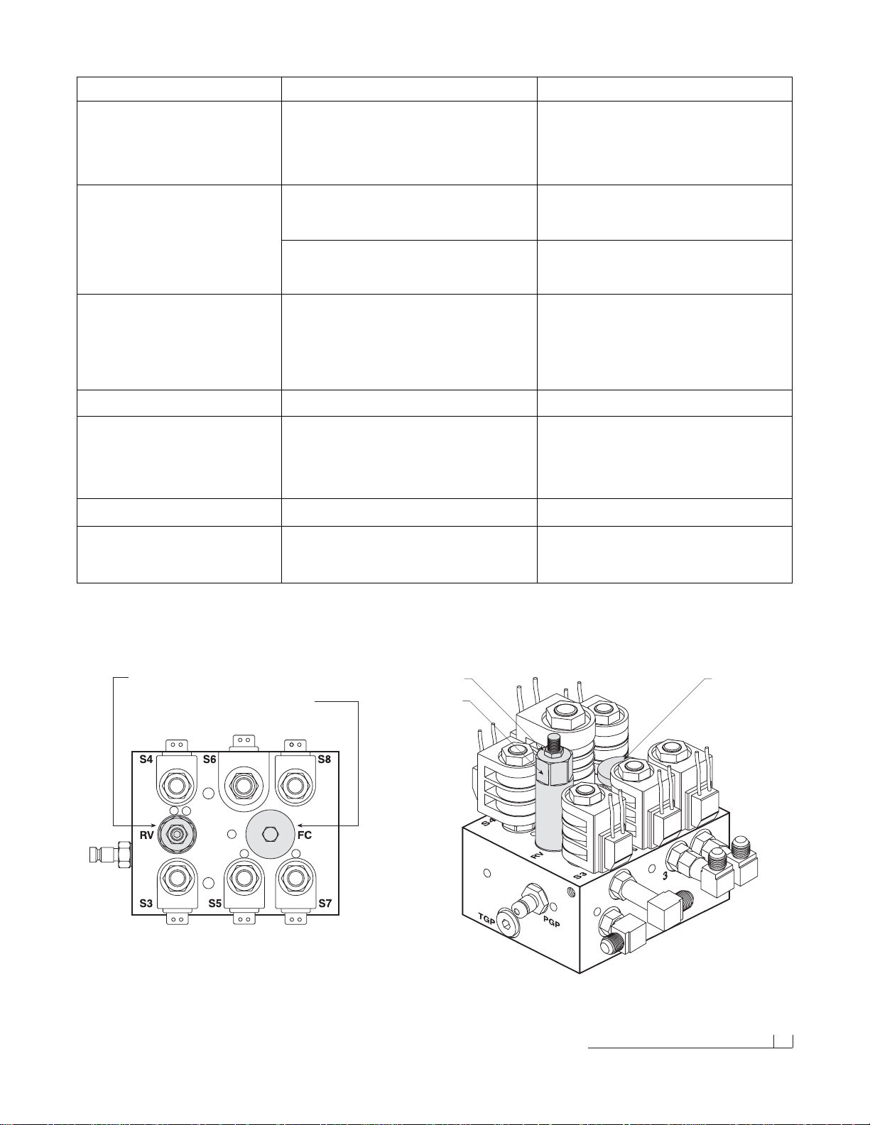
Troubleshooting Guide (2 of 2) 35
Valve
Jam Nut
Variable Flow
Control Valve
Angle Pressure Relief Valve
Variable Flow Control Valve
Clockwise - Decreases Plow Drop Speed
Counterclockwise - Increases Plow Drop Speed
Problem Probable Cause(s) Suggested Remedy
Plow will not lift.Pump works properly. Coils on the manifold may be damaged. Remove both S6 & S7 coils from the cartridge valves.
(Continued from page 34.) Position a screwdriver inside of the coil and push the
draw latch connect/disconnect toggle switch upward.
The screwdriver should be magnetically drawn to the coil.
Replace the coil if there is no action.
Plow will not lift with magnification to the Hydraulic lock in the manifold.This occurs if the voltage is Loosen cartridge valve S6 or S7 to relieve pressure and
S6 & S7 coils. too low on the coils – should be 11.8 volts. retighten.DO NOT OVERTIGHTEN! Valves should be
torqued to a maximum of 24 ft.lbs.
Solenoid cartridge valve may be contaminated. Remove any foreign objects that may be obstructing
proper valve operation.Replace if not operating properly
after cleaning.
Plow will not stay angled when plowing. The angle pressure relief valve is set too low. Check the pressure relief by testing the valve inline with
NOTE:Increasing the pressure relief valve will cause the cylinder. Attach a tee fitting to the angle cylinder
damage to your plow.Do not set the pressure relief hyd raulic adapter and connect the hose and pressure
greater than 3000 PSI (See illustration below) gauge to the tee. Push the plow against a solid object
and record the pressure reading.Note: The setting should
not exceed 3000 PSI.
Plow will not angle, pump works. Review all probable causes above.NOTE:Verify solenoids S3 & S4 for angle functions.
Plow lowers too slow. Variable flow control valve is not adjusted properly. Turn flow control valve counterclockwise in small incre-
(See illustration below) ments and test. NOTE:Never make adjustments when
the plow is in the raised position! Fluid pressure will make
the valve difficult to adjust and serious injury or death can
occur from a falling plow.
Plow drops sporadically. Variable flow control valve is opened too far. Turn clockwise 1/16 of a turn and test.See warning above.
Headlights will not switch from the vehicle to No power or ground to the headlight relay. Verify green/yellow (G/Y) wire for the ground is connected.
the snowplow. Verify black/white (BK/W) wire for the power is connected.
If both are connected properly, replace the headlight relay.
Should your snowplow develop other problems not indicated in the Troubleshooting Guide, contact your local dealer for technical assistance and/or replacement par ts.
Page 38

BLIZZARD
®
LIMITED CONSUMER WARRANTY
This warranty covers defects in mater ial and workmanship except as set forth below.
WARRANTED PARTY:
This warranty applies only to the “Original Purchaser” who purchased this plow from an Author ized Blizzard Dealer,
for personal, family or household use.
TERM OF WARRANTY:
This Blizzard straight blade snowplow is warranted for the following period:
Parts and labor are warranted for one year from date of purchase.
BLIZZARD CORPORATION’S W ARRANTYREMEDY:
Blizzard Corporation will, at its sole discretion, repair or replace defective parts at no charge.
CUSTOMERS RESPONSIBILITY:
To obtain warranty service, the purchaser must return the defective snowplow to any Authorized Blizzard Dealer.
The purchaser must verify the original purchase date.Transportation costs to and from the dealer will be the
responsibility of the purchaser.
ITEMS NOT COVERED UNDER THIS WARRANTY:
This limited warranty does not cover the following:
1. Expendable parts such as cutting edges, plow shoes, hoses, fasteners, blade guides, paint finish, etc.
2. Any snowplow or part thereof which has been repaired or altered by anyone other than an Authorized Blizzard Dealer.
3. Any snowplow or part thereof which has been subject to neglect, misuse, accident, improper installation, maintenance,
or storage.This includes, but is not limited to, corrosion of any electrical components.
4. Snowplows mounted on vehicles other than those for whom Blizzard Corporation has provided a specific
undercarriage system.
5. Blizzard Corporation does not assume liability for damage to the purchaser's vehicle resulting from the attachment
and use of a Blizzard straight blade snowplow. Vehicle r isk is the sole responsibility of the purchaser.
WARRANTY LIMITATIONS:
THIS WARRANTY IS OFFERED IN LIEU OF ANY OTHER EXPRESS WARRANTY.
THE DURATION OF ALL IMPLIED WARRANTIES, INCLUDING BUT NOT LIMITED TO THE IMPLIED
WARRANTIES OF MERCHANTABILITY AND FITNESS FOR A PARTICULAR PURPOSE, ARE LIMITED
TO THE DURATION OF THIS WARRANTY.
BLIZZARD CORPORATION'S LIABILITY IS EXPRESSLY LIMITED TO REPAIR OR REPLACEMENT OF
DEFECTIVE PARTS. BLIZZARD CORPORATION SHALL NOT BE LIABLE FOR CONSEQUENTIAL, INCIDENTAL
OR CONTINGENT DAMAGES WHATSOEVER, EVEN IF DAMAGES ARE CAUSED BY THE NEGLIGENCE OR
FAULT OF BLIZZARD CORPORATION.
State Laws: Some states do not allow exclusion of incidental or consequential damages or the limitations on how
long an implied warranty lasts, so these limitations or exclusions may not apply to you. This warranty gives you
specific legal rights and you may also have other rights which var y from state to state.
This warranty does not apply if you purchased your snowplow for other than personal, family, or household use. If
purchased for other than personal, family or household use, refer to the Blizzard Straight Blade Commercial Warranty.
95 AIRPARK BOULEVARD CALUMET, MICHIGAN 49913 [906] 482-5555
1029-7-99 REV 8/01
Page 39

COMMERCIAL WARRANTY
This warranty covers defects in mater ial and workmanship except as set forth below.
WARRANTED PARTY:
This warranty applies only to the “Original Purchaser” who purchased this plow from an Authorized Blizzard Dealer,
for commercial use.
TERM OF WARRANTY:
This Blizzard straight blade snowplow is warranted for the following period:
Parts and labor are warranted for one year from date of purchase.
BLIZZARD CORPORATION’S W ARRANTY REMEDY :
Blizzard Corporation will, at its sole discretion, repair or replace defective parts at no charge.
CUSTOMERS RESPONSIBILITY:
To obtain warranty service, the purchaser must return the defective snowplow to any Authorized Blizzard Dealer within the
warranty period.The purchaser must verify the original purchase date. Transportation costs to and from the Dealer will be
the responsibility of the purchaser.
ITEMS NOT COVERED UNDER THIS WARRANTY:
This warranty does not cover the following:
1. Expendable parts such as cutting edges, plow shoes, hoses, fasteners, blade guides, paint finish, etc.
2. Any snowplow or part thereof which has been repaired or altered by anyone other than an Authorized Blizzard Dealer.
3. Any snowplow or part thereof which has been subject to neglect, misuse, accident, improper installation, maintenance,
or storage.This includes, but is not limited to, corrosion of any electrical components.
4. Snowplows mounted on vehicles other than those for whom Blizzard Cor poration has provided a specific undercarriage
system.
5. Blizzard Corporation does not assume liability for damage to the purchaser's vehicle resulting from the attachment and
use of a Blizzard straight blade snowplow. Vehicle r isk is the sole responsibility of the purchaser.
LIMITS OF BLIZZARD CORPORATION’S LIABILITIES:
BLIZZARD CORPORATION'S LIABILITY IS EXPRESSLY LIMITED TO REPAIR OR REPLACEMENT OF
DEFECTIVE PARTS. BLIZZARD CORPORATION SHALL NOT BE LIABLE FOR CONSEQUENTIAL, INCIDENTAL
OR CONTINGENT DAMAGES WHATSOEVER, EVEN IF DAMAGES ARE CAUSED BY THE NEGLIGENCE OR
FAULT OF BLIZZARD CORPORATION.
THE FOREGOING WARRANTIES ARE EXCLUSIVE AND IN LIEU OF ALL OTHER EXPRESSED AND IMPLIED
WARRANTIES INCLUDING, BUT NOT LIMITED TO, THE IMPLIED WARRANTIES OF MERCHANTABILITY AND
FITNESS FOR A PARTICULAR PURPOSE.
This warranty does not apply if you purchased your snowplow for personal, family, or household use.
In this case, refer to the Blizzard Straight Blade Limited Consumer Warranty.
BLIZZARD
®
95 AIRPARK BOULEVARD CALUMET, MICHIGAN 49913 [906] 482-5555
1030-7-99 REV 8/01
Page 40

95 Airpark Boulevard
Calumet,MI 49913
[888] 680-860 0
[906] 482-5555
[906] 482-5445 Fax
www.blizzardplows.com
Blizzard and Power Hitch are trademarks of Blizzard Corporation. Blizzard is
registered in the United States Patent and Trademark Office. Loctite and 242 are
registered trademarks of Loctite Corporation, USA. Velcro is a registered trademark
of Velcro Industries B.V. Ford is a trademark of Ford Motor Company. Chevrolet,
GM and Silverado are registered trademarks of General Motors Corporation.
Dodge is a trademark of DaimlerChrysler. Blizzard straight blade snowplows are
protected by U.S. Patents 6,276,076 B1 and 6,393,737; patents pending.
Copyright © 2002 Blizzard Corporation. All rights reserved. Made and printed in
the USA.1265-05-02
 Loading...